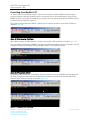
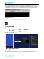
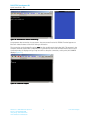
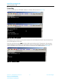
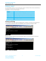
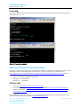
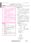
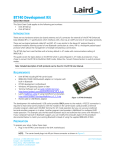
1
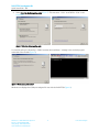
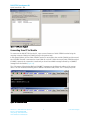
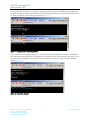
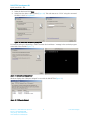
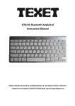
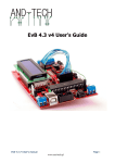
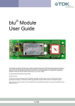
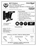
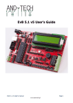
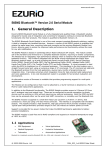
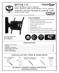
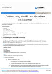
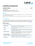
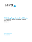
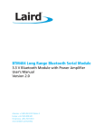
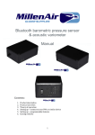
Quick Start Guide (QSG) – Serial Port Profile Laird part # DVK-BT730-SA or DVK-BT730-SC INTRODUCTION This Quick Start Guide demonstrates using the Serial Port Profile (SPP) role on the DVK-BT730 in four different scenarios. REQUIREMENTS DVK-BT730 including BT730 Carrier Board BRBLU03-010A0 USB Bluetooth adapter or Computer with built-in Bluetooth BT730 development motherboard Windows XP Operating System or later Terminal Software such as Laird / EZURiO terminal www.lairdtech.com/zips/LairdTerminal_v6_9_0.zip Laird’s MpBtHost utility (if using MultiPoint functionality) http://www.lairdtech.com/zips/MpBtHost_v3_5_0.zip Figure 1: BT730-SA Development Kit RS232 cable or USB-RS232 adaptor The development kit motherboard’s USB socket provides ONLY power to the module. A RS232 connection is required to have serial communications with the module on the carrier board. Laird provides a terminal emulator program called Laird / EZURiO Terminal for AT mode operation but you can use your preferred terminal emulator program in its place. Another program Laird provides is MpBtHost for multipoint (MP) mode operation. This example uses the Microsoft Bluetooth stack and software that comes with Windows 7. If your computer has built-in Bluetooth support, you can modify the computer aspect of the procedure documented below to match your existing Bluetooth instead of using the supplied BRBLU03-010A0. PREPARATION To prepare your setup, follow these steps: 1. Plug in the BT730 Carrier Board to the DVK motherboard. NOTE: The carrier board plugs into 40-pin Hirose connector as shown in Figure 2. Connector receptacle for BT730 carrier board Figure 2: Carrier board connector Americas: +1-800-492-2320 Option 3 Europe: +44-1628-858-940 Hong Kong: +852 2923 0610 www.lairdtech.com/bluetooth 1 Laird Technologies DVK-BT730 Development Kit Quick Start Guide - SPP 2. Connect RS232/USB-RS232 to the computer and development board. 3. Connect the USB cable to the computer and development board. TP2 is the power switch and there is an LED for power indication. 4. Install your preferred terminal program. We recommend using Laird / Ezurio Terminal. 5. Install MpBtHost, if utilising MP mode. 6. Open your terminal program and select the COM port that the RS232 / USB RS232 Adapter shows (9600 8N1) 7. Check communications by sending AT and then return. This should return OK. 8. Send the following commands to set up the module, as shown in Figure 3: ATS538=1 Auto save link key if pairing is successful ATS512=4 Put the module in discoverable and connectable mode ATS0=1 Auto answer in 1 second AT+BTK=”1234” Legacy pairing code AT&W Store new S Register settings ATZ Reboot the module, so settings become effective Figure 3: Module setup EXCHANGE SERIAL DATA WITH A WINDOWS 7 COMPUTER EQUIPPED WITH A BRBLU03-010A0 USB BLUETOOTH DONGLE The section details serial data exchange between the BT730 and a PC equipped with a BRBLU03-010A0 USB Bluetooth dongle. This communication is illustrated in Figure 4. Figure 4: Serial data exchange Hardware and Software Installation To install the BLBLU03-0101A0 on your Windows PC, complete the following steps: Americas: +1-800-492-2320 Option 2 Europe: +44-1628-858-940 Hong Kong: +852 2923 0610 www.lairdtech.com/bluetooth 2 Laird Technologies DVK-BT730 Development Kit Quick Start Guide - SPP 1. If your PC has a built-in Bluetooth module, disable it. To do so, locate it in the Windows Device Manager, right-click the device, and click Disable. 2. Plug the BRBLU03-010A0 into your computer. Windows 7 automatically detects the device and installs the required drivers. No driver downloads are required. 3. Once installed, check the Windows Device Manager (Figure 5 ). Note the presence of the Microsoft Bluetooth Enumerator and TDK Bluetooth USB Adaptor. These indicate a successful installation. Figure 5: Windows Device Manager Discovery and Pairing The DVK-BT730 is now ready to be discovered by the PC. To initiate this process, follow these steps: 1. Click Start > Devices and Printers. 2. Click Add a device. The DVK-BT730 appears (in this case as Laird 00157B) (Figure 6). If you cannot identify the correct device, refer to the ATI4 command in Preparation. 3. Select the device and click Next. Figure 6: Add a Device window Americas: +1-800-492-2320 Option 2 Europe: +44-1628-858-940 Hong Kong: +852 2923 0610 www.lairdtech.com/bluetooth 3 Laird Technologies DVK-BT730 Development Kit Quick Start Guide - SPP 4. Select Enter the device’s pairing code (Figure 7). This was set to “1234” via AT+BTK=”1234” in the Preparation. Figure 7: Enter the device's pairing code A successful pairing is indicated by a “PAIR 0 <remote device address>” message in the terminal program connected to the module (Figure 8). Figure 8: Device successfully added Windows now displays the COM ports assigned for use with the DVK-BT730 (Figure 9). Americas: +1-800-492-2320 Option 2 Europe: +44-1628-858-940 Hong Kong: +852 2923 0610 www.lairdtech.com/bluetooth 4 Laird Technologies DVK-BT730 Development Kit Quick Start Guide - SPP Figure 9: COM ports displayed Connecting from PC to Module To connect to the DVK-BT730 from the PC, open a second instance of Laird / EZURiO terminal using the outgoing computer COM port (COM43) noted in the previous step. In the example below, the first Laird / EZURiO Terminal is connected to the module (COM16) and the second Laird / EZURiO Terminal is connected to virtual COM 43 on the PC. When the second Laird / EZURiO terminal (COM43) is opened, the connection is made and you should see a RING message followed by a CONNECT message from the module (Figure 10). The 12 characters following the RING and CONNECT messages are the Bluetooth address of the remote device. The four characters following the BT address indicate the UUID, where 1101 is serial port profile. Figure 10: Connection made Americas: +1-800-492-2320 Option 2 Europe: +44-1628-858-940 Hong Kong: +852 2923 0610 www.lairdtech.com/bluetooth 5 Laird Technologies DVK-BT730 Development Kit Quick Start Guide - SPP A transparent data connection is now present. Any text entered into one Laird / EZURiO Terminal appears in the other terminal having been transmitted over the Bluetooth link between the DVK-BT730 modules and the PC. Note the status of the DCD during a connection (Figure 11). Figure 11: Transparent data connection present The connection can be dropped by typing ^^^ into the module terminal window on COM16. This appears in the computer terminal window but is interpreted as a command to enter local command mode. Once in local command mode, OK displays and you may issue ATH to drop the connection; at this point, NO CARRIER displays (Figure 12). Figure 12: Connection dropped Americas: +1-800-492-2320 Option 2 Europe: +44-1628-858-940 Hong Kong: +852 2923 0610 www.lairdtech.com/bluetooth 6 Laird Technologies DVK-BT730 Development Kit Quick Start Guide - SPP EXCHANGE SERIAL DATA WITH A WINDOWS 7 COMPUTER (EQUIPPED WITH A BUILT IN BLUETOOTH MODULE) Figure 13: Serial data exchange with Windows 7 computer The customer can confirm if the computer is equipped with a built-in Bluetooth module by checking Windows Device Manager (Figure 14). Figure 14: Windows Device Manager Discovery and Pairing The DVK-BT730 is now ready to be discovered by the computer. To discover and pair the DVK-BT730, follow these steps: 1. Open Device and Printers. 2. Click Add a device. The DVK-BT730 should now appear, in this case as Laird 00157B (Figure 15). If you cannot identify the correct device, refer to the ATI4 command from the module setup (Figure 3). Figure 15: Add a device Americas: +1-800-492-2320 Option 2 Europe: +44-1628-858-940 Hong Kong: +852 2923 0610 www.lairdtech.com/bluetooth 7 Laird Technologies DVK-BT730 Development Kit Quick Start Guide - SPP 3. Select the device and click Next. 4. Select Enter the device’s pairing code (Figure 16). This code was set to “1234” using the command AT+BTK=”1234” in Preparation. Figure 16: Select Enter the device's pairing code A successful pairing is indicated by a “PAIR 0 <remote device address>” message in the terminal program connected to the module (Figure 17). Figure 17: Successful pairing indicated Windows displays the COM ports assigned for use with the DVK-BT730 (Figure 18). Figure 18: COM ports displayed Americas: +1-800-492-2320 Option 2 Europe: +44-1628-858-940 Hong Kong: +852 2923 0610 www.lairdtech.com/bluetooth 8 Laird Technologies DVK-BT730 Development Kit Quick Start Guide - SPP Connecting from Module to PC To connect from the DVK-BT730 to the PC, open a second instance of Laird / EZURiO terminal using the incoming computer COM port (COM32) noted in the previous step. In the example below, the first Laird / EZURiO Terminal is connected to COM40 as an incoming port on PC and the second Laird / EZURiO Terminal is connected to the module on COM 16. The virtual incoming COM port (COM32) is waiting for an incoming connection, as the DCD indication is deserted (Figure 19). Figure 19: Virtual incoming COM32 port When ATD<Computer BT MAC address> is issued to the module, a SPP connection is initiated (Figure 20). The 12 characters following the CONNECT message are the Bluetooth address of the PC BT module. The four characters following the BT address indicate the UUID, where 1101 is Serial Port Profile. Figure 20: SPP connection initiated A transparent data connection is now present. Any text entered into one Laird / EZURiO Terminal appears in the other having been transmitted over the Bluetooth link between the DVK-BT730 modules and the PC. Note the status of the DCD during a connection (Figure 21). Figure 21: Transparent data connection Americas: +1-800-492-2320 Option 2 Europe: +44-1628-858-940 Hong Kong: +852 2923 0610 www.lairdtech.com/bluetooth 9 Laird Technologies DVK-BT730 Development Kit Quick Start Guide - SPP The connection can be dropped by typing ^^^ into the module terminal window. This appears in the computer terminal window but is interpreted as a command to enter local command mode. Once in local command mode, OK displays and you may issue ATH to drop the connection; at this point, NO CARRIER displays (Figure 22). Figure 22: Connection dropped EXCHANGE SERIAL DATA WITH AN ANDROID PHONE To create an SPP connection to the module, we use the BlueTerm application available from the Play Store. Discovery and Pairing The DVK-BT730 is now ready to be discovered by the Android phone. To do this, follow these steps: 1. From the BlueTerm application, click Menu and select Connect device. 2. Click Scan for devices. The BTM731 should appear in the list. 3. Select the applicable device and enter 1234 as the pairing code. These steps are illustrated in Figure 23. Figure 23: Discovery using an Android phone Connecting Once pairing is successful, a SPP connection is initiated automatically from phone to module (Figure 24). Americas: +1-800-492-2320 Option 2 Europe: +44-1628-858-940 Hong Kong: +852 2923 0610 www.lairdtech.com/bluetooth 10 Laird Technologies DVK-BT730 Development Kit Quick Start Guide - SPP Figure 24: SPP connection initiated automatically A transparent data connection is now present. Any text entered into Laird / EZURiO Terminal appears on BlueTerm. Note the status of the DCD during a connection. The connection can be dropped by typing ^^^ into the module terminal window (left). This appears in the computer terminal window but is interpreted as a command to enter local command mode. Once in local command mode, OK displays and you may issue ATH to drop the connection; at this point, NO CARRIER displays (Figure 25). Figure 25: Connection dropped Americas: +1-800-492-2320 Option 2 Europe: +44-1628-858-940 Hong Kong: +852 2923 0610 www.lairdtech.com/bluetooth 11 Laird Technologies DVK-BT730 Development Kit Quick Start Guide - SPP EXCHANGE SERIAL DATA WITH ANOTHER DVK-BT730 BOARD A pair of DVK-BT730s is required in this example. The first board is configured as in the previous section. On the second board, no specific configuration is required. Discovery and Pairing The first DVK-BT730 with MAC address (0016A4400157B) (on COM16) is ready to be discovered by the second DVK-BT730 with MAC address 0016A440004A which is physically connected to COM1. On the second development board, issue AT+BTIN to discover the first board (Figure 26). Figure 26: Issue AT+BTIN Once the first board is discovered, issue AT+BTW<MAC address> and AT+BTK=”1234” to complete the pairing process. Since Auto Save link is not enabled, AT+BTT is issued to save the link manually (Figure 27). Figure 27: Complete pairing process Americas: +1-800-492-2320 Option 2 Europe: +44-1628-858-940 Hong Kong: +852 2923 0610 www.lairdtech.com/bluetooth 12 Laird Technologies DVK-BT730 Development Kit Quick Start Guide - SPP Connecting On the second board, issue ATD<MAC address> to initiate a SPP connection (Figure 28). Figure 28: Initiate a SPP connection A transparent data connection is now present between the two development boards. Any text entered into one terminal appears on the other. Drop the connection by typing ^^^ into the module terminal window (left). This appears in the computer terminal window but is interpreted as a command to enter local command mode. Once in local command mode, OK displays and you may issue ATH to drop the connection; NO CARRIER displays (Figure 29). Figure 29: Connection dropped Americas: +1-800-492-2320 Option 2 Europe: +44-1628-858-940 Hong Kong: +852 2923 0610 www.lairdtech.com/bluetooth 13 Laird Technologies DVK-BT730 Development Kit Quick Start Guide - SPP AUTOMATIC CONNECT Issue AT+BTR<MAC address> on the second board on COM 1 to initiate an SPP connection automatically. It can attempt to reconnect if the connection is disconnected. Configuration on the second board (COM 1) ATS538=1 ATS500=1 ATS512=1 ATS507=1 ATS505=10 ATS530=15000 AT+BTK=”1234” AT&W ATZ Auto save link key if pairing is successful Default authentication for outgoing connections Idle Mode Allows DSR input to be used to inhibit autoconnect cycle Connection attempts timeout after ten seconds Wait period in milliseconds between connection attempts Legacy pairing code Store S register settings Reboot module Discovery and Pairing The first DVK-BT730 (with MAC address 0016A400157B) on COM16 is now ready to be discovered by the second DVK-BT730 (with MAC address 0016A440004A), which is physically connected to COM1. Figure 30: COM1 Once the first board is discovered, issue AT+BTW<MAC address> on the second board to complete the pairing process (Figure 31). Figure 31: Complete the pairing process Americas: +1-800-492-2320 Option 2 Europe: +44-1628-858-940 Hong Kong: +852 2923 0610 www.lairdtech.com/bluetooth 14 Laird Technologies DVK-BT730 Development Kit Quick Start Guide - SPP Connecting Set the peer address and reboot the module. The second board automatically initiates the SPP connection to the first board (Figure 32). Figure 32: Connection completed ADDITIONAL DOCUMENTATION AND RESOURCES Laird offers a variety of documentation and ancillary information to support our customers through the initial evaluation process and ultimately into mass production. Further documentation is available from www.lairdtech.com/Products/Embedded-Wireless-Solutions/Bluetooth-Radio-Modules/BT700-Series/BT730/ includes: BT730 – Firmware User manual BT730 – Hardware Integration Guide (HIG) DVK-BT730 – User Manual DVK-BT730 – Schematics Software Links FTDI Driver: http://www.ftdichip.com/Drivers/VCP.htm Laird / EZURiO terminal: http://www.lairdtech.com/zips/Bluetooth%20Terminal%20Download.zip Windows 7 Bluetooth: http://windows.microsoft.com/en-us/windows7/add-a-bluetooth-enableddevice-to-your-computer For any additional questions or queries, or to receive local technical support for this Development Kit or for the BT730 module series, please contact [email protected]. Americas: +1-800-492-2320 Option 2 Europe: +44-1628-858-940 Hong Kong: +852 2923 0610 www.lairdtech.com/bluetooth 15 Laird Technologies