1
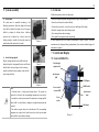
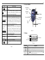
ARGO LAB
AM40-D Pro and AM20-D
Overhead stirrer
User manual
Contents
1
2
3
4
4.1
4.2
5
6
7
7.1
7.2
7.3
8
8.1
9
10
11
12
13
14
Warranty ....................................................................................................... 1
Safety instructions ........................................................................................ 1
Proper use ..................................................................................................... 1
Inspection ..................................................................................................... 1
Receiving Inspection .................................................................................... 1
Listing of Items ............................................................................................ 1
System assembly .......................................................................................... 2
Trial run ........................................................................................................ 2
Control and Display...................................................................................... 2
Control AM40-D Pro .................................................................................... 2
Control AM20-D .......................................................................................... 3
Display.......................................................................................................... 3
Switch on instrument .................................................................................... 4
Initial sequence ............................................................................................. 4
Overload Protection ...................................................................................... 4
Faults ............................................................................................................ 4
Maintenance and Cleaning ........................................................................... 4
Associated standards and regulations ........................................................... 4
Caratteristiche tecniche ................................................................................ 5
Disposal ........................................................................................................ 5
1
1 Warranty
Thank you for purchasing an instrument Argo Lab. This instrument is warranted under
normal use for a period of 24 months from the date of purchase.
The warranty is valid only if the product is in original conditions. It does not apply to
any product or parts of it that have been damaged due to incorrect installation,
improper connections, improper use, accident or abnormal conditions of operation.
The manufacturer declines all responsibility for damage caused by failure to follow
instructions, lack of maintenance and any unauthorized modification.
2 Safety instructions
•
•
•
Read the instructions carefully before use
Ensure that only qualified personnel using this tool
Do not heat flammable or highly volatile substances
•
Before use, make sure the instrument is connected to an outlet with a
ground connection..
• During the work, you must prevent the risk of:
- Spillage of liquids;
- Breakage of glass containers
• Follow the safety instructions, guidelines and safety regulations.
• Do not touch moving parts.
• Place the instrument in a suitable area, on a stable, clean, non-slip, dry and fireproof.
Do not use the tool in explosive atmospheres, containing hazardous substances or
under water.
• Increase gradually the speed.
• Observe the container when you set the speed to avoid splashing of the sample. If the
instrument is not working properly, please decrease the speed of the motor.
• Attach the accessories on the move to avoid damage.
• Only use the original standard accessories listed in the "accessories", and follow the
installation instructions to ensure safety.
• Check the good condition of the instrument and accessories before use. Never use
damaged components. The safety and operating performance are guaranteed only if the
instrument and accessories described are in order. Accessories must also be firmly
connected to the device.
• Do not cover the instrument during operation.
• The voltage on the rating plate must correspond to the mains voltage.
• Keep away from strong magnetic fields.
• The instrument can be switched off or disconnecting it from disconnecting the cable
from the instrument itself .
• The instrument may only be opened by trained service technicians.
• Keep out of the instrument by electromagnetic fields.
3 Proper use
The instrument has been designed to mix liquids of different densities in school labs,
chemical, pharmaceutical, industrial etc. This instrument is not suitable for using in
residential areas.
4 Inspection
4.1 Receiving Inspection
Unpack the instrument carefully and check for any damages which may have arisen
during transport. If it happens, please contact supplier for technical support.
Note:
If there is any apparent damage to the system,
please do not connect to the power line.
4.2 Listing of Items
Item
Qty
Main unit
1
Power cable
1
User manual
1
Key of drill chuck
1
Table 1
2
5 System assembly
6 Trial run
Follow the instructions below to trial operate:
a. Install stand
The stand must be assembled according to the
following instructions. Adjust the height of the main
unit, and the distance from main unit to the support
holder by rotating the locking device. Anti-drop
protector can be adjusted up or down, ensure the
locking position is suitable for fixing the main unit,
and then attach the main unit to the stand.
• Ensure the required operating voltage and power supply voltage matched.
• Ensure the socket must be earthed reliably.
• Connect the power cable,ensure the power on and begin self-checking.
• Rotate the stirring button and set stirring speed.
• Press stirring button and start stirring.
• Press again the stirring button and stop stirring.
Picture 1
If these operations above are normal, the instrument is ready to operate. If not, the
instrument may be damaged during transportation, please contact technical support of
manufacturer/supplier.
7 Control and Display
b. Install stirring impeller
Plug the stirring impeller into the drill chuck, and
adjust the depth of stirring impeller into vessel. Rotate
the drill chuck with your fingers to fix the stirring
impeller, and then clockwise tighten evenly the drill
chuck using chuck key.
7.1 Control AM40-D Pro
Picture 2
Push through
agitator shaft
Speed/torque
LED
LCD Display
Picture 3
Note:
1. Overhead stirrer is a high-speed running device. The system are
required to lock securely the corresponding components in each step of
the assembly to avoid any movement of the main unit or stirring impeller
which would be caused harm or damage to peripheral instrument and
personnel.
2. The stand is a support device for overhead stirrer. The corresponding
components are required to be locked securely to avoid any movement
which would be caused harm or damage.
MODE switch
Power switch /
overload LED
Speed control
knob
Power
switch
Drill chuck
Picture 4
3
7.2 Control AM20-D
Items
Speed control
button Speed
Mode switch knob
Mode
Default settings
Set stirring speed, press the button to start/stop stirring
function.
Shift speed and torque display. LCD displays the current
speed value at initial running. LCD displays the current
torque value when press the mode knob.
LCD display
LCD displays the real working state and all setting values.
Speed/torque light
RPM/Torque
Yellow/Green LED display light. Different color of LED
lights show the value for speed or torque that LCD screen
currently displays. Yellow LED light shows that LCD
screen currently displays speed. Green LED light shows
that LCD screen currently displays torque.
Foro passante
per asta
Speed/torque
LED
LCD Display
Power switch LED
Speed control
knob
Power
switch
Drill chuck
Green/Red LED display light.
Power switch
/Overload
protection light
Power/Overload
LED light shows green when switch on, LED light shows
red when starts overload protection. When the torque
reaches limited value, overload protection function will be
started. At the same time overload protection light flashes,
while the system stops running.
Drill chuck
Can be held stirring impellers.
Push-through
agitator shaft
If needed, shaft can push-through agitator.
Power switch I/O
Switch ON or OFF the instrument.
Speed control
button Speed
Set stirring speed, press the button to start/stop stirring
function.
Picture 5
7.3 Display
Set
Faults
Table 2
Remote control
Set
Set value/display
Err
PC
Picture 6
Characters
Set
PC
Err
Value
set/display area
Description
Display when set target speed value.
Display when using external probe.
Display in case of error happening.
When Set display, this area shows setting value; When Set
disappears, this area shows running value.
Table 3
8 Switch on instrument
8.1 Initial sequence
Place the overhead stirrer in safe and stable surface and connect power cable.
• Switch ON instrument.
• The instrument begins self-checking.
• When initialization is over, displays “set”, at the same time the area of value
setting/display flashes that indicate can be set speed value.
• Rotate speed control button to set stirring speed.
• LCD display no longer flashes when press speed button, “set” disappear, the stirring
function start.
• Press speed button again, LCD display flashes, “set” display, the stirring function
close.
9 Overload Protection
Overhead Stirrer works continuous, the motor current is electronically limited to
achieve security stall and overload protection. When the torque reaches limited
value, overload protection function will be started. At the same time overload
protection light flashes.
•
-
•
Starts overload protection
When the setting speed value does not match the current medium viscosity,
starts overload protection.
When the motor output shaft is stuck, motor protection starts.
Refer to Chapter 9 for the solutions of overload protection and motor
protection.
10 Faults
•
•
•
-
Instrument can not be powered ON when start stirring function.
Check whether the power cable is connected.
Speed can not reach set point.
The setting speed value does not match the current medium viscosity, please
reduce speed then re-start.
Stirring function suddenly stop
Overload protection light changed to red, display area shows “Er 03”, indicate the
-
4
current failure is “overload protection”. When the setting speed value does not
match medium viscosity that caused overload protection, should be first pressing
speed control button to stop stirring function. Restart stirring after lowered
setting speed value. If overhead protection continues starting, then repeat the
process and gradually reduce the speed.
Overload protection light changed to red, display area shows “Er 04”, indicate the
current failure is “motor protection”. When the motor output shaft is stuck that
caused motor protection, should be first
11 Maintenance and Cleaning
Proper maintenance can keep instrument working properly and lengthen its lifetime.
Do not spray cleanser into the instrument when cleaning.
Do not remove the power line when cleaning. Only use recommended cleansers:
Dyes
Isopropyl alcohol
Construction materials
Water containing tenside / Isopropyl alcohol
Cosmetics
Water containing tenside / Isopropyl alcohol
Foodstuffs
Water containing tenside
Fuels
Water containing tenside
Before using other method for cleaning or decontamination, the user must ascertain
with the manufacturer that this method will not damage the instrument. Wear the
proper protective gloves during cleaning of the instrument.
12 Associated standards and regulations
Construction in accordance with the following safety standards:
EN 61010-1
UL 3101-1
CAN/CSA C22.2(1010-1) EN 61010-2-10
Construction in accordance with the following EMC
standards:
EN 61326-1
5
13 Caratteristiche tecniche
Max. stirring quantity (H2O) [L]
Motor rating input [W]
Motor rating output [ W]
Voltage [VAC]
Frequency [Hz]
Power [W]
Speed range [rpm]
Speed display accuracy [rpm]
Speed display
Max. torque [Ncm]
Overload protection
Motor protect
Max. viscosity [mPas]
Chuck range diameter [mm]
Stand (dia. x l) [mm]
Dimension[W x H x D] [mm]
Weight [kg]
Protection class acc. to DIN/EN 60529
Temperature [℃]
Permission relative humidity [%]
RS232 interface
14 Disposal
40 (AM40-D Pro) / 20 (AM20-D)
120 / 60
100 / 50
100-240
Information regarding the disposal of electrical and
electronic equipment European Union.
Electrical and electronic equipment marked with the symbol on
the side cannot be disposed of in landfills.
50/60
130 / 70
50-2200 / 0-2200
±1
LCD
60
LED light flash, auto stop
LED light flash, auto stop
50000
0.5-13
14 x 220
83 x 220 x 186
2,8 / 2,6
IP21
5-40
80
Yes / No
In accordance with EU Directive 2002/96/EC, the European users of electrical and
electronic equipment have the opportunity to give back to the distributor or
manufacturer upon purchase of a new one.
The illegal disposal of electrical and electronic equipment is punished with an
administrative fine.