1
Cat. No. W427-E1-01
SYSMAC
CX-Programmer IEC
Ver. 1.0
WS02-CPIC1-E
CS1-H (FB)/CJ1-H (FB) CPU Units
OPERATION MANUAL
CX-Programmer IEC
Ver. 1.0
WS02-CPIC1-E
CS1-H (FB)/CJ1-H (FB) CPU Units
Operation Manual
Produced September 2003
iv
Notice:
OMRON products are manufactured for use according to proper procedures by a qualified operator
and only for the purposes described in this manual.
The following conventions are used to indicate and classify precautions in this manual. Always heed
the information provided with them. Failure to heed precautions can result in injury to people or damage to property.
!DANGER
Indicates an imminently hazardous situation which, if not avoided, will result in death or
serious injury.
!WARNING
Indicates a potentially hazardous situation which, if not avoided, could result in death or
serious injury.
!Caution
Indicates a potentially hazardous situation which, if not avoided, may result in minor or
moderate injury, or property damage.
OMRON Product References
All OMRON products are capitalized in this manual. The word “Unit” is also capitalized when it refers to
an OMRON product, regardless of whether or not it appears in the proper name of the product.
The abbreviation “Ch,” which appears in some displays and on some OMRON products, often means
“word” and is abbreviated “Wd” in documentation in this sense.
The abbreviation “PLC” means Programmable Controller. “PC” is used, however, in some Programming Device displays to mean Programmable Controller.
Visual Aids
The following headings appear in the left column of the manual to help you locate different types of
information.
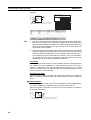
Note Indicates information of particular interest for efficient and convenient operation of the product.
1,2,3...
1. Indicates lists of one sort or another, such as procedures, checklists, etc.
OMRON, 2003
All rights reserved. No part of this publication may be reproduced, stored in a retrieval system, or transmitted, in any form, or
by any means, mechanical, electronic, photocopying, recording, or otherwise, without the prior written permission of
OMRON.
No patent liability is assumed with respect to the use of the information contained herein. Moreover, because OMRON is constantly striving to improve its high-quality products, the information contained in this manual is subject to change without
notice. Every precaution has been taken in the preparation of this manual. Nevertheless, OMRON assumes no responsibility
for errors or omissions. Neither is any liability assumed for damages resulting from the use of the information contained in
this publication.
v
vi
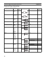
TABLE OF CONTENTS
PRECAUTIONS . . . . . . . . . . . . . . . . . . . . . . . . . . . . . . . . . . .
xi
1
Intended Audience . . . . . . . . . . . . . . . . . . . . . . . . . . . . . . . . . . . . . . . . . . . . . . . . . . . . . . . . .
xii
2
General Precautions . . . . . . . . . . . . . . . . . . . . . . . . . . . . . . . . . . . . . . . . . . . . . . . . . . . . . . . .
xii
3
Safety Precautions . . . . . . . . . . . . . . . . . . . . . . . . . . . . . . . . . . . . . . . . . . . . . . . . . . . . . . . . .
xii
4
Application Precautions. . . . . . . . . . . . . . . . . . . . . . . . . . . . . . . . . . . . . . . . . . . . . . . . . . . . .
xiii
5
Installation Precaution . . . . . . . . . . . . . . . . . . . . . . . . . . . . . . . . . . . . . . . . . . . . . . . . . . . . . .
xv
SECTION 1
Introduction. . . . . . . . . . . . . . . . . . . . . . . . . . . . . . . . . . . . . . .
1
1-1
Introducing the CX-Programmer IEC . . . . . . . . . . . . . . . . . . . . . . . . . . . . . . . . . . . . . . . . . .
2
1-2
Function Blocks . . . . . . . . . . . . . . . . . . . . . . . . . . . . . . . . . . . . . . . . . . . . . . . . . . . . . . . . . . .
7
1-3
Variables . . . . . . . . . . . . . . . . . . . . . . . . . . . . . . . . . . . . . . . . . . . . . . . . . . . . . . . . . . . . . . . .
13
1-4
Converting Function Block Definitions to Library Files . . . . . . . . . . . . . . . . . . . . . . . . . . . .
20
1-5
Operating Procedures. . . . . . . . . . . . . . . . . . . . . . . . . . . . . . . . . . . . . . . . . . . . . . . . . . . . . . .
21
SECTION 2
Creating Function Blocks. . . . . . . . . . . . . . . . . . . . . . . . . . . .
23
2-1
Procedural Flow. . . . . . . . . . . . . . . . . . . . . . . . . . . . . . . . . . . . . . . . . . . . . . . . . . . . . . . . . . .
24
2-2
Procedures . . . . . . . . . . . . . . . . . . . . . . . . . . . . . . . . . . . . . . . . . . . . . . . . . . . . . . . . . . . . . . .
26
SECTION 3
Specifications . . . . . . . . . . . . . . . . . . . . . . . . . . . . . . . . . . . . . .
47
3-1
Function Block Specifications . . . . . . . . . . . . . . . . . . . . . . . . . . . . . . . . . . . . . . . . . . . . . . . .
48
3-2
Instance Specifications . . . . . . . . . . . . . . . . . . . . . . . . . . . . . . . . . . . . . . . . . . . . . . . . . . . . .
57
3-3
Restrictions on Function Blocks . . . . . . . . . . . . . . . . . . . . . . . . . . . . . . . . . . . . . . . . . . . . . .
60
3-4
Function Block Applications Guidelines. . . . . . . . . . . . . . . . . . . . . . . . . . . . . . . . . . . . . . . .
65
3-5
CPU Unit Specifications and Battery Replacement . . . . . . . . . . . . . . . . . . . . . . . . . . . . . . .
67
Appendices
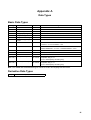
A
Data Types . . . . . . . . . . . . . . . . . . . . . . . . . . . . . . . . . . . . . . . . . . . . . . . . . . . . . . . . . . . . . .
81
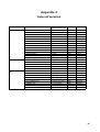
B
Structured Text Keywords . . . . . . . . . . . . . . . . . . . . . . . . . . . . . . . . . . . . . . . . . . . . . . . . . .
83
C
External Variables . . . . . . . . . . . . . . . . . . . . . . . . . . . . . . . . . . . . . . . . . . . . . . . . . . . . . . . . .
85
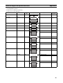
D
Instruction Support and Operand Restrictions . . . . . . . . . . . . . . . . . . . . . . . . . . . . . . . . . . .
87
Index. . . . . . . . . . . . . . . . . . . . . . . . . . . . . . . . . . . . . . . . . . . . . 123
Revision History . . . . . . . . . . . . . . . . . . . . . . . . . . . . . . . . . . . 127
vii
TABLE OF CONTENTS
viii
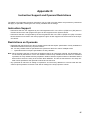
About this Manual:
This manual describes the function blocks and related functionality of the CX-Programmer IEC and
includes the sections described on the next page. The CX-Programmer IEC can be used only for SYSMAC CS-series and CJ-series CPU Units that support function blocks. These CPU Units are indicated
as the CS1-H (FB)/CJ1-H (FB) CPU Units.
This manual describes only CX-Programmer IEC operations that are different from those of the nonIEC CX-Programmer. For operations not related to function blocks, refer to the CX-Programmer Operation Manual (enclosed, Cat. No. W414). This manual also provides only specifications and information on the battery replacement procedure for the CS1-H (FB)/CJ1-H (FB) CPU Units. For other
information, refer to the CS/CJ-series manuals.
Please read this manual and related manuals carefully and be sure you understand the information
provided before attempting to install or operate the CX-Programmer IEC or the CS1-H (FB)/CJ1-H
(FB) CPU Units. Be sure to read the precautions provided in the following section.
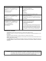
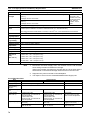
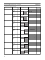
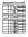
Manuals Related to the CX-Programmer IEC
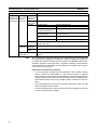
Name
SYSMAC WS02-CPIC1-E
CX-Programmer IEC Operation Manual
(CS1G-CPU42H/44H (FB), CS1H-CPU65H/
67H (FB), CJ1G-CPU42H/43H/44H (FB) CPU
Units)
SYSMAC WS02-CXPC1-E-V3@
CX-Programmer Operation Manual
Cat. No.
Contents
W427
(This manual)
Describes the functionality unique to the CX-Programmer IEC
based on function blocks. Functionality that is the same as
that of the CX-Programmer is described in W414 (enclosed).
W414
Provides information on how to use the CX-Programmer for
all functionality except for function blocks.
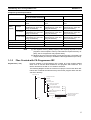
Manuals Related to the CS1-H (FB) and CJ1-H (FB) CPU Units
Name
SYSMAC CS Series
CS1G/H-CPU@@-EV1, CS1G/H-CPU@@H
Programmable Controllers
Operation Manual
Cat. No.
Contents
W339
Provides an outline of and describes the design, installation,
maintenance, and other basic operations for the CS-series
PLCs.
The following information is included:
An overview and features
The system configuration
Installation and wiring
I/O memory allocation
Troubleshooting
Use this manual together with the W394.
SYSMAC CJ Series
CJ1G/H-CPU@@H, CJ1M-CPU@@, CJ1GCPU@@
Programmable Controllers
Operation Manual
W393
Provides an outline of and describes the design, installation,
maintenance, and other basic operations for the CJ-series
PLCs.
The following information is included:
An overview and features
The system configuration
Installation and wiring
I/O memory allocation
Troubleshooting
Use this manual together with the W394.
ix
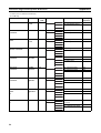
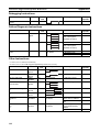
Name
SYSMAC CS/CJ Series
CS1G/H-CPU@@-EV1, CS1G/H-CPU@@H,
CJ1G/H-CPU@@H, CJ1M-CPU@@, CJ1GCPU@@
Programmable Controllers
Programming Manual
Cat. No.
Contents
W394
Describes programming and other methods to use the functions of the CS/CJ-series PLCs.
SYSMAC CS/CJ Series
CS1G/H-CPU@@-EV1, CS1G/H-CPU@@H,
CJ1G/H-CPU@@H, CJ1M-CPU@@, CJ1GCPU@@
Programmable Controllers
Instructions Reference Manual
SYSMAC CS/CJ Series
CS1G/H-CPU@@-EV1, CS1G/H-CPU@@H,
CS1W-SCB21-V1/41-V1, CS1W-SCU21/41,
CJ1G/H-CPU@@H, CJ1M-CPU@@, CJ1GCPU@@, CJ1W-SCU21/41
Communications Commands
Reference Manual
W340
The following information is included:
Programming
Tasks
File memory
Other functions
Use this manual together with the W339 or W393.
Describes the ladder diagram programming instructions supported by CS/CJ-series PLCs.
When programming, use this manual together with the Operation Manual (CS1: W339 or CJ1: W393) and Programming
Manual (W394).
W342
Describes the communications commands that can be
addressed to CS/CJ-series CPU Units.
The following information is included:
C-series (Host Link) commands
FINS commands
Note: This manual describes commands that can be sent to
the CPU Unit without regard for the communications path,
which can be through a serial communications port on the
CPU Unit, a communications port on a Serial Communications Unit/Board, or a port on any other Communications
Unit.
Overview of Contents
Precautions provides general precautions for using the CX-Programmer IEC.
Section 1 provides an overview of CX-Programmer IEC functionality and general information on function blocks.
Section 2 provides information on and procedures for creating function blocks.
Section 3 provides technical specifications and restrictions for function blocks and information on the
battery replacement procedure.
The Appendices provide additional information required for programming, including data types, ST
language keywords, a table of external variables, and tables of instructions support and operand
restrictions.
!WARNING Failure to read and understand the information provided in this manual may result in personal injury or death, damage to the product, or product failure. Please read each section
in its entirety and be sure you understand the information provided in the section and
related sections before attempting any of the procedures or operations given.
x
PRECAUTIONS
This section provides general precautions for using the CX-Programmer IEC.
The information contained in this section is important for the safe and reliable application of the CX-Programmer
IEC. You must read this section and understand the information contained before attempting to set up or operate
the CX-Programmer IEC.
1
2
3
4
5
Intended Audience . . . . . . . . . . . . . . . . . . . . . . . . . . . . . . . . . . . . . . . . . . . . .
General Precautions . . . . . . . . . . . . . . . . . . . . . . . . . . . . . . . . . . . . . . . . . . . .
Safety Precautions. . . . . . . . . . . . . . . . . . . . . . . . . . . . . . . . . . . . . . . . . . . . . .
Application Precautions . . . . . . . . . . . . . . . . . . . . . . . . . . . . . . . . . . . . . . . . .
Installation Precaution. . . . . . . . . . . . . . . . . . . . . . . . . . . . . . . . . . . . . . . . . . .
xii
xii
xii
xiii
xv
xi
1
Intended Audience
1
Intended Audience
This manual is intended for the following personnel, who must also have
knowledge of electrical systems (an electrical engineer or the equivalent).
• Personnel in charge of installing FA systems.
• Personnel in charge of designing FA systems.
• Personnel in charge of managing FA systems and facilities.
2
General Precautions
The user must operate the product according to the performance specifications described in the operation manuals.
Before using the product under conditions which are not described in the
manual or applying the product to nuclear control systems, railroad systems,
aviation systems, vehicles, combustion systems, medical equipment, amusement machines, safety equipment, and other systems, machines, and equipment that may have a serious influence on lives and property if used
improperly, consult your OMRON representative.
Make sure that the ratings and performance characteristics of the product are
sufficient for the systems, machines, and equipment, and be sure to provide
the systems, machines, and equipment with double safety mechanisms.
This manual provides information for programming and operating the product.
Be sure to read this manual before attempting to use the product and keep
this manual close at hand for reference during operation.
!WARNING It is extremely important that a PLC and all PLC Units be used for the specified purpose and under the specified conditions, especially in applications that
can directly or indirectly affect human life. You must consult with your
OMRON representative before applying a PLC System to the above-mentioned applications.
3
Safety Precautions
!WARNING Confirm safety sufficiently before transferring I/O memory area status from the
CX-Programmer IEC to the CPU Unit. The devices connected to Output Units
may malfunction, regardless of the operating mode of the CPU Unit. Caution
is required in respect to the following functions.
• Transferring from the CX-Programmer IEC to real I/O (CIO Area) in the
CPU Unit using the PLC Memory Window.
• Transferring from file memory to real I/O (CIO Area) in the CPU Unit using
the Memory Card Window.
!Caution Confirm safety at the destination node before transferring a program to
another node or changing contents of the I/O memory area. Doing either of
these without confirming safety may result in injury.
!Caution Execute online editing only after confirming that no adverse effects will be
caused by extending the cycle time. Otherwise, the input signals may not be
readable.
xii
4
Application Precautions
!Caution Confirm safety sufficiently before monitoring power flow and present value
status in the Ladder Section Window or when monitoring present values in the
Watch Window. If force-set/reset or set/reset operations are inadvertently performed by pressing short-cut keys, the devices connected to Output Units
may malfunction, regardless of the operating mode of the CPU Unit.
4
Application Precautions
Observe the following precautions when using the CX-Programmer IEC.
• User programs cannot be uploaded to the CX-Programmer IEC.
• Observe the following precautions before starting the CX-Programmer
IEC.
• Exit all applications not directly related to the CX-Programmer IEC.
Particularly exit any software such as screen savers, virus checkers,
email or other communications software, and schedulers or other applications that start up periodically or automatically.
• Disable sharing hard disks, printers, or other devices with other computers on any network.
• With some notebook computers, the RS-232C port is allocated to a
modem or an infrared line by default. Following the instructions in documentation for your computer and enable using the RS-232C port as
a normal serial port.
• With some notebook computers, the default settings for saving energy
do not supply the rated power to the RS-232C port. There may be both
Windows settings for saving energy, as well as setting for specific computer utilities and the BIOS. Following the instructions in documentation for your computer, disable all energy saving settings.
• Do not turn OFF the power supply to the PLC or disconnect the connecting cable while the CX-Programmer IEC is online with the PLC. The computer may malfunction.
• Confirm that no adverse effects will occur in the system before attempting
any of the following. Not doing so may result in an unexpected operation.
• Changing the operating mode of the PLC.
• Force-setting/force-resetting any bit in memory.
• Changing the present value of any word or any set value in memory.
• Check the user program for proper execution before actually running it on
the Unit. Not checking the program may result in an unexpected operation.
• When online editing is performed, the user program and parameter area
data in CS1-H (FB)/CJ1-H (FB) CPU Units is backed up in the built-in
flash memory. The BKUP indicator will light on the front of the CPU Unit
when the backup operation is in progress. Do not turn OFF the power
supply to the CPU Unit when the BKUP indicator is lit. The data will not be
backed up if power is turned OFF. To display the status of writing to flash
memory on the CX-Programmer, select Display dialog to show PLC Memory Backup Status in the PLC properties and then select Windows − PLC
Memory Backup Status from the View Menu.
xiii
4
Application Precautions
• If a project file created with the non-IEC CX-Programmer is read and the
Device Type is changed to one that supports function blocks, the default
function block memory allocations (function block instance area, refer to
2-2-6 Setting the FB Instance Areas) will overlap with any of the following
addresses used in the user program, causing errors when compiling:
W000 to W511, EM 20480 to EM 32767 in the last EM bank, T1024 to
T4095, and C1024 to C4095.
If addresses are duplicated and an error occurs, either change the function block memory allocations or the addresses used in the user program.
• If a user program containing function blocks created on the CX-Programmer IEC is downloaded to a CPU Unit that does not support function
blocks (e.g., the CS1-H or CJ1-H), all instances will be treated as illegal
commands and it will not be possible to edit or execute the user program.
• The CX-Programmer IEC cannot be connected online to any CS-series or
CJ-series CPU Unit not supported by it.
• CXP files from the non-IEC version of CX-Programmer for CPU Unit models not supported by the CX-Programmer IEC cannot be read by the CXProgrammer IEC.
• When specifying the first or last word of multiple words for an instruction
operand, I/O parameters cannot be used to pass data to or from I/O variables. Internal array variables must be used. This applies, for example, to
the first source word for SEND(090) or the starting word or end word for
BSET(071).
For multiword operands, an array variable must be prepared in advance
with the required number of elements and the data must be set for the array in the function block definition. The first or last element in the array variable is then specified for the operand to set the first or last word. Refer to
3-4 Function Block Applications Guidelines for details.
• Input values are passed from parameters to input variables before the
algorithm is processed. Consequently, values cannot be read from
parameters to input variables within the algorithm. If it is necessary to
read a value within the execution cycle of the algorithm, do not pass the
value from a parameter. Assign the value to an internal variable and use
an AT setting (specified addresses).
In a similar fashion, output variables are passed to the corresponding parameters after the algorithm is processed. Consequently, values cannot be
written from output variables to parameters within the algorithm. If it is necessary to write a value within the execution cycle of the algorithm, do not
write the value to a parameter. Assign the value to an internal variable and
use an AT setting (specified addresses).
• Always use variables with AT settings in the following cases.
• The first destination word at the remote node for SEND(090) and the
first source word at the remote node for RECV(098)
• Auxiliary Area flags and bits that are not registered for external variables and that need to be read or written within the execution cycle of
an algorithm
xiv
5
Installation Precaution
5
Installation Precaution
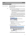
If the non-IEC version of CX-Programmer is already installed when installing
the CX-Programmer IEC, the following overwrite confirmation dialog box will
be displayed.
Always click the Yes Button and install CX-Server version 2.00.
If the No Button is clicked, it will not be possible to use the CX-Programmer
IEC (i.e., it will not be possible to select a Device Type that supports function
blocks (FB)).
Even if the Yes Button is clicked, the non-IEC version of CX-Programmer will
not be uninstalled and can be used as normal.
xv
Installation Precaution
xvi
5
SECTION 1
Introduction
This section introduces the CX-Programmer IEC and explains the features that are not contained in the non-IEC version of
CX-Programmer.
1-1
1-2
1-3
Introducing the CX-Programmer IEC. . . . . . . . . . . . . . . . . . . . . . . . . . . . . . .
2
1-1-1
Functions and Features . . . . . . . . . . . . . . . . . . . . . . . . . . . . . . . . . . .
2
1-1-2
Specifications . . . . . . . . . . . . . . . . . . . . . . . . . . . . . . . . . . . . . . . . . .
3
1-1-3
Files Created with CX-Programmer IEC . . . . . . . . . . . . . . . . . . . . .
5
1-1-4
CX-Programmer IEC Menus . . . . . . . . . . . . . . . . . . . . . . . . . . . . . .
6
Function Blocks . . . . . . . . . . . . . . . . . . . . . . . . . . . . . . . . . . . . . . . . . . . . . . .
7
1-2-1
Outline . . . . . . . . . . . . . . . . . . . . . . . . . . . . . . . . . . . . . . . . . . . . . . .
7
1-2-2
Advantages of Function Blocks . . . . . . . . . . . . . . . . . . . . . . . . . . . .
7
1-2-3
Function Block Structure . . . . . . . . . . . . . . . . . . . . . . . . . . . . . . . . .
8
Variables . . . . . . . . . . . . . . . . . . . . . . . . . . . . . . . . . . . . . . . . . . . . . . . . . . . . .
13
1-3-1
Introduction. . . . . . . . . . . . . . . . . . . . . . . . . . . . . . . . . . . . . . . . . . . .
13
1-3-2
Variable Usage and Properties . . . . . . . . . . . . . . . . . . . . . . . . . . . . .
14
1-3-3
Variable Properties . . . . . . . . . . . . . . . . . . . . . . . . . . . . . . . . . . . . . .
15
1-3-4
Property Settings and Variable Usage. . . . . . . . . . . . . . . . . . . . . . . .
17
1-3-5
Internal Allocation of Variable Addresses . . . . . . . . . . . . . . . . . . . .
18
1-4
Converting Function Block Definitions to Library Files . . . . . . . . . . . . . . . .
20
1-5
Operating Procedures . . . . . . . . . . . . . . . . . . . . . . . . . . . . . . . . . . . . . . . . . . .
21
1-5-1
Creating Function Blocks and Executing Instances . . . . . . . . . . . . .
21
1-5-2
Reusing Function Blocks . . . . . . . . . . . . . . . . . . . . . . . . . . . . . . . . .
22
1
Section 1-1
Introducing the CX-Programmer IEC
1-1
1-1-1
Introducing the CX-Programmer IEC
Functions and Features
The CX-Programmer IEC is a Programming Device that can use standard
IEC 61131-3 function blocks. The CX-Programmer IEC is the same as nonIEC CX-Programmer version 3.0 except that function block functionality has
been added. The CX-Programmer IEC is compatible with the CS/CJ-series
PLCs and has the following features.
• Project files (.cxp) created with non-IEC CX-Programmer can be imported
and reused. Function blocks can be created in ladder language by cutting
and pasting program rungs.
• User-defined processes can be converted to block format by using function blocks.
• Function block algorithms can be written in the ladder programming language or in the structured text (ST) language. (See note.)
• When ladder programming is used, ladder programs created with nonIEC CX-Programmer can be reused by copying and pasting.
• When ST language is used, it is easy to program mathematical processes that would be difficult to enter with ladder programming.
Note
The ST language is an advanced language for industrial control
(primarily PLCs) that is described in IEC 61131-3. The ST language supported by CX-Programmer IEC conforms to the
IEC 61131-3 standard.
• Function blocks can be created easily because variables do not have to
be declared in text. They are registered in variable tables.
A variable can be registered automatically when it is entered in a ladder or
ST program. Registered variables can also be entered in ladder programs
after they have been registered in the variable table.
• A single function block can be converted to a library function as a single
file, making it easy to reuse function blocks for standard processing.
• A program check can be performed on a single function block to easily
confirm the function block’s reliability as a library function.
• One-dimensional variable arrays are supported, so data handling is easier for many applications.
Note
2
The IEC 61131 standard was defined by the International Electrotechnical
Commission (IEC) as an international programmable controller (PLC) standard. The standard is divided into 7 parts. Specifications related to PLC programming are defined in Part 3 Textual Languages (IEC 61131-3).
Section 1-1
Introducing the CX-Programmer IEC
1-1-2
Specifications
Specifications that are not listed in the following table are identical to the specifications for CX-Programmer Version 3.0.
Item
Specifications
Model number
WS02-CPIC1-E
Setup disk
Compatible CPU Units
CD-ROM
Only the following CS1-H and CJ1-H CPU Units are compatible. No other
CPU Units can be used. (See note.)
• CS1G-CPU42H/44H (FB)
• CS1H-CPU65H/67H (FB)
• CJ1G-CPU42H/43H/44H (FB)
Note Non-IEC CX-Programmer project files (.cxp) created for the following
models can be read and reused by changing the Device Type to one
that supports function blocks. Once the existing project file has been
changed, CX-Programmer IEC function blocks can be used.
• CS1G-CPU42H/43H/44H/45H
• CS1H-CPU63H/64H/65H/66H/67H
• CJ1G-CPU42H/43H/44H/45H
• CJ1H-CPU65H/66H
Compatible
computers
Computer
CPU
OS
Memory
Hard disk space
Monitor
CS/CJ Series Function Restrictions
• Program Restrictions
Subroutine numbers 128 to 1023 cannot be used in Subroutine Instructions
(SBS, GSBS, RET, MCRO, and SBN). Only numbers 0 to 127 can be used.
• Instructions Not Supported in Function Block Definitions
Block Program Instructions (BPRG and BEND), Subroutine Instructions
(SBS, GSBS, RET, MCRO, and SBN), Jump Instructions (JMP, CJP, and
CJPN), Step Ladder Instructions (STEP and SNXT), Immediate Refresh
Instructions (!), I/O REFRESH (IORF), ONE-MS TIMER (TMHH), and HIGHSPEED TIMER (TIMH)
• Timer/Counter PV refreshing method: Binary only
For details, refer to 3-3 Restrictions on Function Blocks.
IBM PC/AT or compatible
133 MHz Pentium or faster with Windows 98, SE, or NT 4.0
Microsoft Windows 98, SE, Me, 2000, XP, or NT 4.0 (with service pack 6 or
higher)
64 Mbytes min. with Windows 98, SE, or NT 4.0
Refer to Computer System Requirements below for details.
100 Mbytes min. available disk space
SVGA (800 × 600 pixels) min.
Note Use “small font” for the font size.
CD-ROM drive
COM port
One CD-ROM drive min.
One RS-232C port min.
3
Section 1-1
Introducing the CX-Programmer IEC
Functions not
supported by
non-IEC CXProgrammer
Item
Defining
and creating function blocks
Specifications
Number of
896 max. per CPU Unit
function block
definitions
Function
64 characters max.
block names
Variables
Variable names
Inputs, Outputs, Internals, and Externals
64 max. (not including EN and ENO)
Allocation of addresses
used by variables
Automatic allocation (The allocation range can
be set by the user.)
Actual address specification
Supported
Array specifications
Supported (one-dimensional arrays only)
Function blocks can be created in ladder programming language or structured
text (ST, see note).
Language
Creating
instances
30,000 characters max.
Variable types
Number of I/O variables in
function block definitions
Number of
instances
2,048 max. per CPU Unit
Instance
names
30,000 characters max.
Storing function blocks as Each function block definition can be stored as one file for reuse in other
library files
projects.
Note
The ST language conforms to the IEC 61131-3 standard, but CX-Programmer
IEC supports only assignment statements, selection statements (CASE and
IF statements), iteration statements (FOR, WHILE, and REPEAT statements),
arithmetic operators, logical operators, comparison operators, and comments.
Other statements and operators are not supported. For details, refer to Appendix B Structured Text Keywords.
Restrictions on Particular CPU Units
• If a user program created with CX-Programmer IEC contains function
blocks, it cannot be downloaded to a CPU Unit that does not support
function blocks. If the program is downloaded to a CPU Unit that does not
support function blocks, all function block instances will be treated as illegal instructions and it will not be possible to edit or execute the user program.
• The CX-Programmer IEC cannot be placed online with a CPU Unit that
does not support function blocks.
• The CX-Programmer IEC cannot read non-IEC CX-Programmer CXP files
for CPU Units it does not support.
4
Section 1-1
Introducing the CX-Programmer IEC
Computer System Requirements
Item
Windows 95 (See note 2.),
98, or NT 4.0 Service Pack 6
Computer
CPU
Memory
(RAM)
capacity
OS
Windows 2000 or Me
Windows XP
IBM PC/AT or compatible
Pentium class 133 MHz or
faster
Programs up to 64 Mbytes min.
30 Ksteps
(96 Mbytes min. when also
using CX-Simulator)
For programs up 128 Mbytes min.
to 120 Ksteps
(128 Mbytes min. when also
using CX-Simulator)
IBM PC/AT or compatible
Pentium class 150 MHz or
faster
96 Mbytes min.
(128 Mbytes min. when also
using CX-Simulator)
192 Mbytes min.
(192 Mbytes min. when also
using CX-Simulator)
IBM PC/AT or compatible
Pentium class 300 MHz or
faster
128 Mbytes min.
(192 Mbytes min. when also
using CX-Simulator)
256 Mbytes min.
(256 Mbytes min. when also
using CX-Simulator)
For programs
192 Mbytes min.
over 120 Ksteps (192 Mbytes min. when also
using CX-Simulator)
256 Mbytes min.
(256 Mbytes min. when also
using CX-Simulator)
384 Mbytes min.
(384 Mbytes min. when also
using CX-Simulator)
Hard disk space
Display
100 Mbytes min. available
100 Mbytes min. available
100 Mbytes min. available
800 × 600 SVGA min.
800 × 600 SVGA min.
800 × 600 SVGA min.
CD-ROM drive
One CD-ROM drive min.
One CD-ROM drive min.
One CD-ROM drive min.
COM port
One RS-232C port min.
Note
(1) The required memory (RAM) capacity is the capacity required to create
programs. If the computer’s memory is less than the required memory capacity, the CX-Programmer may operate slowly.
(2) Windows 95 cannot be used when connecting through a Controller Link
Support Board (PCI Card) or SYSMAC LINK Support Board (PCI Card).
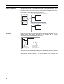
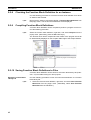
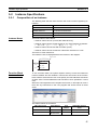
1-1-3
Files Created with CX-Programmer IEC
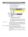
Project Files (*.cxi)
Projects created in CX-Programmer IEC contain all of the program-related
data, such as function block definitions and programs with instances. The
data is stored as a file with a “cxi” filename extension.
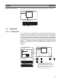
The following diagram shows the contents of a project. The function block definitions are created at the same directory level as the program within the relevant PLC directory.
Project file (.cxi)
PLC1
Global symbol table
I/O table
PLC Setup
PLC memory table
Program (with rung comments)
Local symbol table
Section 1 (with instances)
Section 2 (with instances)
END section (with instances)
Function block definitions
FunctionBlock1
FunctionBlock2
PLC2
Instances created
in program
sections.
Each function block can be
stored in a separate
definition file (.cxf).
5
Section 1-1
Introducing the CX-Programmer IEC
Note
Project files created with non-IEC CX-Programmer (*.cxp) can be read
(imported) but cannot be saved. After importing a file, the CX-Programmer
IEC functions can be used if the Device Type is changed to one that supports
function blocks. Once the Device Type has been changed, existing program
rungs can be copied and pasted, function blocks can be created in the ladder
programming language, and the data can be saved as a CX-Programmer IEC
project file (*.cxi).
Function Block/Library
Files (.cxf)
A function block definition created in a project in CX-Programmer IEC can be
saved as a file (1 definition = 1 file) so that definitions can be read into other
programs and reused.
Project Text Files in CXProgrammer IEC (*.cxt)
The project files created in CX-Programmer IEC (*.cxi) can be saved as CXT
text files (*.cxt) just as in the non-IEC CX-Programmer.
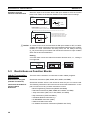
1-1-4
CX-Programmer IEC Menus
The following tables list CX-Programmer IEC menus that are different from
non-IEC CX-Programmer menus. Menus that are the same are not listed.
Main Menu
Main menu
Insert
PLC
Submenu
Shortcut
Function Block Invocation
F
Function Block Parameter
P
Mem- Function Block
--ory
Memory Allocation
Function Block
--Memory Statistics
Function
Creates an instance of a function block in the program at the
present cursor location.
When the cursor is located to the left of an input variable or the right
of an output variable, sets the variable’s input or output parameter.
Sets the range of addresses (function block instance areas) internally allocated to the selected instance’s variables.
Checks the status of the addresses internally allocated to the
selected instance’s variables.
Function Block
Memory Address
---
Checks the addresses internally allocated to each variable in the
selected instance.
Optimize Function
Memory
---
Optimizes the allocation of addresses internally allocated to variables.
Main Popup Menus
Popup Menu for Function Block Definitions
Popup menu
Insert Function Block
Ladder
Function
Structured Text
Creates a function block definition with a ladder programming language algorithm.
Creates a function block definition with an ST language algorithm.
From file
Reads a function block definition from a function block library file (*.cxf).
Popup Menu for Inserted Function Blocks
Popup menu
Open
Function
Displays the contents of the selected function block definition on the right side of the window.
Save Function Block File
Compile
Saves the selected function block definition in a file.
Compiles the selected function block definition.
Popup Menu for Instances
Popup menu
Edit
Update Invocation
Function
Changes the instance name.
When a function block definition’s I/O variables have been changed after the instance
was created, an error will be indicated by displaying the instance’s left bus bar in red.
This command updates the instance with the new information and clears the error.
Go To Function Block Definition Displays the selected instance’s function block definition on the right side of the window.
6
Section 1-2
Function Blocks
1-2
1-2-1
Function Blocks
Outline
A function block is a basic program element containing a standard processing
function that has been defined in advance. Once the function block has been
defined, the user just has to insert the function block in the program and set
the I/O in order to use the function.
As a standard processing function, a function block does not contain actual
addresses, but variables. The user sets addresses or constants in those variables. These address or constants are called parameters. The addresses
used by the variables themselves are allocated automatically by the CX-Programmer IEC for each program.
With the CX-Programmer IEC, a single function block can be saved as a single file and reused in other PLC programs, so standard processing functions
can be made into libraries.
Program 2
Copy of function block A
Function block A
Program 1
Variable
Copy of function block A
Standard
program section
written with
variables
Input
Variable Variable
Output
Output
Define in advance.
Insert in
program.
Set
Set
Copy of function block A
Save function
block as a file.
Convert to
library function.
Function
block A
Input
Variable Variable
Output
To another PLC program
Reuse.
1-2-2
Advantages of Function Blocks
Function blocks allow complex programming units to be reused easily. Once
standard programming is created in a function block and saved in a file, it can
be reused just by placing the function block in a program and setting the
parameters for the function block’s I/O. The ability to reuse existing function
blocks will save significant time when creating/debugging programs, reduce
coding errors, and make the program easier to understand.
Structured
Programming
Structured programs created with function blocks have better design quality
and require less development time.
Easy-to-read “Black Box”
Design
The I/O operands are displayed as variable names in the program, so the program is like a “black box” when entering or reading the program and no extra
time is wasted trying to understand the internal algorithm.
Use One Function Block
for Multiple Processes
Many different processes can be created easily from a single function block by
using the parameters in the standard process as input variables (such as
timer SVs, control constants, speed settings, and travel distances).
7
Section 1-2
Function Blocks
Reduce Coding Errors
Coding mistakes can be reduced because blocks that have already been
debugged can be reused.
Data Protection
The variables in the function block cannot be accessed directly from the outside, so the data can be protected. (Data cannot be changed unintentionally.)
Improved Reusability with
Variable Programming
The function block’s I/O is entered as variables, so it isn’t necessary to change
data addresses in a block when reusing it.
Creating Libraries
Processes that are independent and reusable (such as processes for individual steps, machinery, equipment, or control systems) can be saved as function block definitions and converted to library functions.
The function blocks are created with variable names that are not tied to actual
addresses, so new programs can be developed easily just by reading the definitions from the file and placing them in a new program.
Compatible with
Multiple Languages
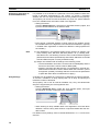
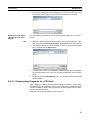
1-2-3
Mathematical expressions can be entered in structured text (ST) language.
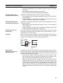
Function Block Structure
A function block consists of the function block definition that is created in
advance and the function block instances that are inserted in the program.
Function Block
Definition
The function block definition is the basic element that makes the function
block reusable. Each function block definition contains the algorithm and variable definitions, as shown in the following diagram.
Function Block Definition
Example: CLOCK PULSE
Example: CLOCK PULSE
1. Algorithm
tim_b
TIMX tim_a OFF_TIME
Algorithm
tim_a
TIMX tim_b ON_TIME
Variable definitions
ENO
2. Variable Definitions
Usage
Name
Internal
Internal
Input
Input
tim_a
tim_b
ON_TIME
OFF_TIME
Type
TIMER
TIMER
INT
INT
1. Algorithm
Standardized programming is written with variable names rather than actual I/
O memory addresses. In the CX-Programmer IEC, algorithms can be written
in either ladder programming or structured text.
2. Variable Definitions
The variable table lists each variable’s usage (input, output, or internal) and
properties (data type, etc.). For details, refer to 1-3 Variables.
8
Section 1-2
Function Blocks
Number of Function Block
Definitions
Up to 896 function block definitions can be created for one CPU Unit.
Instances
When a function block definition is inserted in a program, the function block
uses a particular memory area for its variables. Each function block definition
that is inserted in the program is called an “instance” or “function block
instance.” Each instance is assigned an identifier called an “instance name.”
By generating instances, a single function block definition can be used to process different I/O data with the same function.
Not yet in program
and memory not yet
allocated
(abstract).
Function Block Definition FB1
Block instance in program with memory
allocated. (object)
Standard
program unit
with variable
names a, b, c,
etc.
Instance
Program
Insert in
program.
Automatic
allocation
Input
data
a
b
c
Output data
Output data
2. Parameters
Table defining usage
and properties of
variables a, b, c, etc.
Memory
used
Instance FB1_1 of function block definition FB1
1. Algorithm
Automatic
allocation
Memory
for FB1_2
Insert in
program.
Instance FB1_2 of function block definition FB1
Input
data
a
b
c
Note
Memory
for FB1_1
Different I/O data
can be processed
with the same
function.
Output data
Output data
Instances are managed by names. More than one instance with the same
name can also be inserted in the program. If two or more instances have the
same name, they will use the same internal variables. Instances with different
names will have different internal variables.
For example, consider three function blocks that use a timer as an internal
variable. In this case all instances will have to be given different names. If
more than one instance uses the same name, the use of the timer would be
duplicated, which is not allowed.
If, however, internal variables are not used or they are used only temporarily
and initialized the next time an instance is executed, the same instance name
can be used to save memory.
instance_A
TIMER_FB
Function Block Definition
TIMER_FB
Variable Definitions
Internal variable: WORK_NUM
Use same internal variables.
instance_A
TIMER_FB
Use different internal variables.
instance_B
TIMER_FB
9
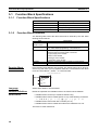
Section 1-2
Function Blocks
Number of Instances
Multiple instances can be created from a single function block definition. Up to
2,048 instances can be created for a single CPU Unit. The allowed number of
instances is not related to the number of function block definitions or the number of tasks in which the instances are inserted.
Function Block Definition A
Program
Instance example of function block definition A
sample01
1. Algorithm
Standard program
unit with variable
names a, b, c, etc.
Insert in
program.
a
b
c
2. Parameters
Table defining usage
and properties of
variables a, b, c, etc.
Program
Instance example of function block definition A
sample02
a
b
c
Parameters
Each time an instance is created, the actual I/O memory addresses or constants used to pass data to and from the I/O variables are set. These
addresses or constants are called parameters.
Instance of Function Block Definition A
Input 0.00
a
Input 3.00
c
Set the constants or
input source addresses
from which to pass data..
b
Output 2.00
Set the constant or
output destination
address to which to pass
data.
Here, it is not the input source address itself, but the contents at the input
address in the form and size specified by the variable data type that is passed
to the function block. In a similar fashion, it is not the output destination
address itself, but the contents for the output address in the form and size
specified by the variable data type that is passed from the function block.
10
Section 1-2
Function Blocks
Even if an input source address (i.e., an input parameter) or an output destination address (i.e., an output parameter) is a word address, the data that is
passed will be the data in the form and size specified by the variable data type
starting from the specified word address.
Program
Instance of Function Block Definition A
Input D100
m
Input D200
n
k
Output D300
Examples:
If m is type WORD, one word of data from D100 will be passed to the
variable.
If n is type DWORD, two words of data from D200 and D201 will be
passed to the variable.
If k is type LWORD, four words of data from the variable will be passed
to the D300 to D303.
Note
(1) Only addresses in the following areas can be used as parameters: CIO
Area, Auxiliary Area, DM Area, EM Area (banks 0 to C), Holding Area,
and Work Area.
The following cannot be used: Index and data registers (both direct and
indirect specifications) and indirect addresses to the DM Area and EM
Area (both in binary and BCD mode).
(2) Local and global symbols in the user program can also be specified as
parameters. To do so, however, the data size of the local or global symbol
must be the same as the data size of the function block variable.
(3) When an instance is executed, input values are passed from parameters
to input variables before the algorithm is processed. Output values are
passed from output variables to parameters just after processing the algorithm. If it is necessary to read or write a value within the execution cycle of the algorithm, do not pass the value to or from a parameter. Assign
the value to an internal variable and use an AT setting (specified addresses).
!Caution When specifying the first or last word of multiple words for an instruction operand, I/O parameters cannot be used to pass data to or from I/O variables.
Internal array variables must be used. This applies, for example, to the first
source word for SEND(090) or the starting word and end word for BSET(071).
For multiword operands, an array variable must be prepared in advance with
the required number of elements and the data must be set for the array in the
function block definition. The first or last element in the array variable is then
specified for the operand to set the first or last word. Refer to 3-4 Function
Block Applications Guidelines for details.
11
Section 1-2
Function Blocks
!Caution Input values are passed from parameters to input variables before the algorithm is processed. Consequently, values cannot be read from parameters to
input variables within the algorithm. If it is necessary to read a value within the
execution cycle of the algorithm, do not pass the value from a parameter.
Assign the value to an internal variable and use an AT setting (specified
addresses). In a similar fashion, output variables are passed to the corresponding parameters after the algorithm is processed. Consequently, values
cannot be written from output variables to parameters within the algorithm. If it
is necessary to write a value within the execution cycle of the algorithm, do
not write the value to a parameter. Assign the value to an internal variable and
use an AT setting (specified addresses).
■ Reference Information
A variety of processes can be created easily from a single function block by
using parameter-like elements (such as fixed values) as input variables and
changing the values passed to the input variables for each instance.
Example: Creating 3 Instances from 1 Function Block Definition
Instance
CASCADE_01
Algorithm
Cyclic task 0
CASCADE_01
P_On
EN
&20
Internal and I/O
variables
&10
CONTROL
ENO
1.
ON_TIME
OFF_TIME
Function Block Definition
Example: CONTROL
Algorithm
Variables
Example:
There are 3 FB
instances and each
has its own I/O and
internal variables.
Instance
CASCADE_02
Algorithm
CASCADE_02
P_On
EN
&15
Internal and I/O
variables
Instance
CASCADE_03
Algorithm
&10
CONTROL
ENO
1.
ON_TIME
OFF_TIME
Cyclic task 1
CASCADE_03
P_On
EN
&7
Internal and I/O
variables
&8
CONTROL
ENO
1.
ON_TIME
OFF_TIME
If internal variables are not used, if processing will not be affected, or if the
internal variables are used in other locations, the same instance name can be
used at multiple locations in the program.
Cyclic taskCASCADE
0
P_On
&100
The same instance can be
used at multiple locations.
&130
CONTROL
EN
ENO
PARA_1
PARA_2
Function block definition
Example: CONTROL
Algorithm
Variables
Instance
CASCADE
Algorithm
Internal and I/O
variables
P_On
&50
&150
CASCADE
CONTROL
EN
ENO
PARA_1
PARA_2
Cyclic taskCASCADE
1
P_On
&100
&200
CONTROL
EN
ENO
PARA_1
PARA_2
Some precautions are required when using the same memory area. For
example, if an instance containing a timer instruction is used in more than one
program location, the same timer number will be used causing coil duplication, and the timer will not function properly if both instructions are executed.
12
Section 1-3
Variables
Registration of Instances
Each instance name is registered in the global symbol table as a file name.
Program
Instance (sample) of function block definition A
a
b
c
The instance is registered in the
global symbol table with the instance
name as the variable name.
Name
Type
sample FB [FunctionBlock1]
The function block definition
name is registered after FB in
square parentheses [ ].
Instance name
1-3
1-3-1
Address/
value
N/A[Auto]
Variables
Introduction
In a function block, the addresses are not entered as actual I/O memory
addresses, they are all entered as variable names. Each time an instance is
created, the actual addresses used by the variable are allocated automatically
in the specified I/O memory areas by the CX-Programmer IEC. Consequently,
it isn’t necessary for the user to know the actual I/O memory addresses used
in the function block, just as it isn’t necessary to know the actual memory allocations in a computer. A function block differs from a subroutine in this
respect, i.e., the function block uses variables and the addresses are like
“black boxes.”
Example:
Program
Function block definition A
Instance of function block definition A
Standard program section with
variable names a, b, c, etc.
b
a
c
MOV
Table indicating usage and
prpperties of variables a, b, c, etc.
Usage: Inputs
a
c
AT
Initial Value Retained
BOOL
BOOL
Usage: Outputs
Prpperties:
Name Type
BOOL
b
AT
Input 0.00
a
Input 3.00
c
b
Output 2.00
Specify inputs and outputs
at the same time.
Status of 0.00 (1 or 0) is
passed to a.
0.00 1
a
1
Status of b (1 or 0) is
passed to 2.00.
b
1
2.00
1
Status of 3.00 (1 or 0) is
passed to c.
Prpperties:
Name Type
Insert in
program.
Initial Value Retained
3.00 0
c
0
The system automatically allocates the
addresses used by variables a, b, and c. For
example, when W100 to W120 is set as the
system’s non-retained memory area, bit
addresses such as a = W10000, b = W10001,
and c = W10002 will be allocated.
13
Section 1-3
Variables
1-3-2
Variable Usage and Properties
Variable Usage
The following variable types (usages) are supported.
Internals:
Internal variables are used only within an instance. They cannot
be used pass data directly to or from I/O parameters.
Inputs:
Input variables can input data from input parameters outside of
the instance. The default input variable is an EN (Enable) variable, which passes input condition data.
Outputs:
Output variables can output data to output parameters outside of
the instance. The default output variable is an ENO (Enable Out)
variable, which passes the instance’s execution status.
Externals: External variables are global symbols registered in advance as
variables in the CX-Programmer IEC, such as Condition Flags
and some Auxiliary Area bits.
The following table shows the number of variables that can be used and the
kind of variable that is created by default for each of the variable usages.
Variable
usage
Inputs
Outputs
Internals
Externals
14
Allowed number
Up to 64 per function
block (not including EN)
Variable created by default
EN (Enable): Receives an input condition.
The instance is executed when the variable
is ON. The instance is not executed when
the variable is OFF.
Up to 64 per function
EN (Enable Output): Outputs the function
block (not including ENO) block’s execution status.
The variable is turned ON when the
instance starts being executed. It can be
turned OFF by the algorithm. The variable
remains OFF when the instance is not executed.
Unlimited
None
Reserved variables only
(28)
Global symbols registered in advance as
variables in the CX-Programmer IEC, such
as Conditions Flags or some Auxiliary Area
bits.
For details, refer to Appendix C External
Variables.
Section 1-3
Variables
1-3-3
Variable Properties
Variables have the following properties.
Variable Name
The variable name is used to identify the variable in the function block. It
doesn’t matter if the same name is used in other function blocks.
Note
Data Type
The variable name can be up to 30,000 characters long, but must not begin
with a number. Also, the name cannot contain two underscore characters in a
row. There are no other restrictions. (Consequently, it is acceptable to use
addresses such as “A20300” as variable names.)
Select one of the following data types for the variable. Any of the following
types may be used.
Data type
BOOL
Content
OK
Outputs
OK
Internals
OK
Bit data
1 bit
INT
UNIT
Integer
Unsigned integer
16 bits
16 bits
OK
OK
OK
OK
OK
OK
DINT
UDINT
Double integer
Unsigned double integer
32 bits
32 bits
OK
OK
OK
OK
OK
OK
LINT
ULINT
Long (8-byte) integer
Unsigned long (8-byte) integer
64 bits
64 bits
OK
OK
OK
OK
OK
OK
WORD
DWORD
16-bit data
32-bit data
16 bits
32 bits
OK
OK
OK
OK
OK
OK
LWORD
REAL
64-bit data
Real number
64 bits
32 bits
OK
OK
OK
OK
OK
OK
LREAL
TIMER
Long real number
Timer (See note 1.)
64 bits
1 bit or 16 bits
OK
OK
OK
OK
OK
OK
COUNTER
Counter (See note 2.)
1 bit or 16 bits
OK
OK
OK
Note
Size
Inputs
(1) When a variable is entered in the timer number (0 to 4095) operand of a
timer instruction, such as TIM or TIMH, the data type will be TIMER.
When this variable is used as an operand in another instruction, it will be
treated as the timer Completion Flag if the operand takes 1-bit data or as
a timer PV if the operand takes 16-bit data. The timer PVs are 16-bit binary data because the CX-Programmer IEC can use only binary format
for the PVs. The TIMER data type cannot be used in ST language function blocks.
(2) When a variable is entered in the counter number (0 to 4095) operand of
a counter instruction, such as CNT or CNTR, the data type will be
COUNTER. When this variable is used as an operand in another instruction, it will be treated as a counter Completion Flag if the operand takes
1-bit data or as a counter PV if the operand takes 16-bit data. The counter
PVs are 16-bit binary data because the CX-Programmer IEC can use
only binary format for the PVs.
The COUNTER data type cannot be used in ST language function blocks.
15
Section 1-3
Variables
AT Settings (Allocation to
an Actual Addresses)
It is possible to set a variable to a particular I/O memory address rather than
having it allocated automatically by the system. To specify a particular
address, the user can input the desired I/O memory address in this property.
This property can be set for internal variables only. Even if a specific address
is set, the variable name must still be used in the algorithm.
• Setting Procedure
Click the Advanced Button, select the AT (Specified Address) option, and
input the desired address in the Address field.
Select the AT option.
Input the address.
• Even though a specified address is being used for the variable, specify
the variable name in the algorithm in the function block definition. (Specify
a variable name regardless of whether an address is being specified for
the variable.)
Note
(1) Only addresses in the following areas can be used for AT settings: CIO
Area, Auxiliary Area, DM Area, EM Area (banks 0 to C), Holding Area,
and Work Area. The following cannot be used: Index and data registers
(both direct and indirect specifications) and indirect addresses to the DM
Area and EM Area (both in binary and BCD mode).
(2) Always use variables with AT settings in the following cases.
• The first destination word at the remote node for SEND(090) and the
first source word at the remote node for RECV(098)
• Auxiliary Area flags and bits that are not registered for external variables and that need to be read or written within the execution cycle of
an algorithm (Auxiliary Area flags and bits can be used as parameters
to pass data when these conditions do not apply.)
Array Settings
A variable can be treated as a single array of data with the same properties.
To convert a variable to an array, specify that it is an array and specify the
maximum number of elements.
This property can be set for internal variables only. Only one-dimensional
arrays are supported by the CX-Programmer IEC.
• Setting Procedure
Click the Advanced Button, select the Array Variable option, and input
the maximum number of elements in the Size field.
Select the Array
Variable option.
Input the maximum
number of elements.
• When entering an array variable name in the algorithm in a function block
definition, enter the array index number in square brackets after the variable number.
For details on array settings, refer to Variable Definitions in 3-1-2 Function Block
Elements.
16
Section 1-3
Variables
■ Reference Information
When specifying the first or last word of multiple words for an instruction operand, I/O parameters cannot be used to pass data to or from I/O variables.
Internal array variables must be used. For multiword operands, an array variable must be prepared in advance with the required number of elements and
the data must be set for the array in the function block definition. The first or
last element in the array variable is then specified for the operand to set the
first or last word. Refer to 3-4 Function Block Applications Guidelines for
details. Refer to Appendix D Instruction Support and Operand Restrictions for
the instructions and operands that require designation of a first or last word
address for a multiword operand.
Initial Value
This is the initial value set in a variable before the instance is executed for the
first time. Afterwards, the value may be changed as the instance is executed.
For example, set a boolean variable (bit) to either 1 (TRUE) or 0 (FALSE). Set
a WORD variable to a value between 0 and 65,535 (between 0000 and FFFF
hex).
If an initial value is not set, the variable will be set to 0. For example, a boolean variable would be 0 (FALSE) and a WORD variable would be 0000 hex.
Retain
Select the Retain Option if you want an internal variable’s data to be retained
when the PLC is turned ON again and when the PLC starts operating.
• Setting Procedure
Select the Retain Option.
Select the Retain option.
1-3-4
Property Settings and Variable Usage
The following table shows which properties must be set, can be set, and cannot be set, based on the variable usage.
Property
Variable usage
Name
Internals
Must be set.
Inputs
Must be set.
Outputs
Must be set.
Type
AT (specified address)
Must be set.
Can be set.
Must be set.
Cannot be set.
Must be set.
Cannot be set.
Initial Value
Retain
Can be set.
Can be set.
Can be set.
Cannot be set.
Can be set.
Cannot be set.
17
Section 1-3
Variables
1-3-5
Internal Allocation of Variable Addresses
When an instance is created from a function block definition, the CX-Programmer IEC internally allocates addresses to the variables. Addresses are allocated to all of the variables registered in the function block definition except for
variables that have been assigned actual addresses with the AT Settings
property.
FB instance areas
Program
Instance of function block definition A
Non-retained area
Starting address 15
a
Input 0.00
b Output 2.00
t
Output 5.00
Note: Variable c is an internal
variable, so it is not displayed.
b
t
AT
Initial Value Retained
BOOL
TIMER
Name Type
c
Setting Internal Allocation
Areas for Variables
AT
Automatic allocation of
addresses by system
Size (Completion
Flags)
Starting
address
C Area
Size (Completion
Flags)
Example
2000.00
InitialValue Retained
BOOL 2000.00
T Area
Counter area
YES
Usage: Internals
Properties:
Size (words)
Timer area
Starting address
Name Type
0
H, D, or E
Area
Initial Value Retained
Usage: Outputs
Properties:
Size (words)
Retained area
Starting address 15
Usage: Inputs
Properties:
Name Type AT
a
BOOL
0
CIO, H, W,
D, or E Area
Manual allocation of address to
variable in FB by AT Settings option.
The user sets the function block instance areas in which addresses are allocated internally by the CX-Programmer IEC. The variables are allocated automatically by the system to the appropriate instance area set by the user. The
following data areas can be set for the instance areas.
Non-retained Area
• Applicable variables: Internal variables that do not have the Retain Option
selected to retain the variable’s content when the power is turned ON or
program execution starts.
Note
TIMER and COUNTER data types are not allocated to the non-retained area.
• Allowed data areas: I/O (CIO Area), H (Holding Area), W (Work Area), D
(DM Area), or E (EM Area)
Note
Bit data can be accessed even if the DM or EM Area is specified.
• Units: Set in word units.
• Default allocation: W000 to W511
Retained Area
• Applicable variables: Internal variables that have the Retain Option
selected to retain the variable’s content when the power is turned ON or
program execution starts.
Note
TIMER and COUNTER data types are not allocated to the retained
area.
• Allowed data areas: H (Holding Area), D (DM Area), or E (EM Area)
Note
Bit data can be accessed even if the DM or EM Area is specified.
• Units: Set in word units.
• Default allocation: Words 20480 to 32767 of the last EM bank
Note
18
The default area is words 20480 to 32767 of the last EM bank. The
last EM bank number depends on the CPU Unit being used.
Section 1-3
Variables
Timer Area
• Applicable variables: Variables that have the data type property set to
TIMER.
• Allowed data areas: Timer Completion Flags (1 bit each) or timer PVs (16
bits each)
• Default allocation: T3072 to T4095 timer Completion Flags (1 bit each) or
timer PVs (16 bits each)
Counter Area
• Applicable variables: Variables that have the data type property set to
COUNTER.
• Allowed data areas: Counter completion flags (1 bit each) or counter PVs
(16 bits each)
• Default allocation: C3072 to C4095 counter Completion Flags (1 bit each)
or counter PVs (16 bits each)
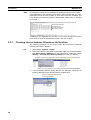
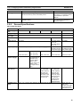
Setting Procedure
Select Memory - Function Block Memory Allocation from the PLC Menu.
Set the areas in the following dialog box.
Set the 4 areas.
Setting Example:
Instance area
Start Address
End Address
Size
Non Retain
Retain
W400
E0_20480
W449
E0_32767
50
12288
Timers
Counters
T3072
C3072
T4095
C4095
1024
1024
Specifying Instance Area Addresses from the User Program
If there are instructions in the user program that access addresses in the
instance areas, the CX-Programmer IEC will display an error on the Output
Window’s Compile (Program Check) Tab Page in the following cases:
• When attempting to download the user program to the CPU Unit or
attempting to write the program through online editing. (Neither downloading or editing will be possible.)
• When a program check is performed by the user by selecting Program Compile (Program Check) or Compile All Programs (Check) from the
PLC Menu.
19
Section 1-4
Converting Function Block Definitions to Library Files
For example, if W000 to W511 is specified as the non-retained instance area
and W000 is used in the ladder program, the following error will be displayed
when compiling: ERROR: ... (omitted) ... Address - W0.00 is reserved for
Function Block use.
Program
P_Off
FB
ENO
EN
1.0
Instance area
Start
address
Non-retained area
W0
Size
512
Retained area
W0.00
Timer area
3.0
Counter area
Compile
error
Note
1-4
When a variable is added or deleted, addresses are automatically re-allocated
to the instance areas. Consecutive addresses are required for each instance,
so all of the variables will be allocated to a different block of addresses if the
original block of addresses cannot accommodate the change in variables.
This will result in an unused block of addresses. A memory optimization function can be executed to eliminate the unused area of memory so that the
memory is used more efficiently.
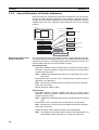
Converting Function Block Definitions to Library Files
A function block definition created in the CX-Programmer IEC can be stored
as a single file known as a function block definition file with filename extension.cxf. These files can be reused in other projects (PLCs).
Project
Project
Function block definition
Example: CLOCK_PULSE
Function block definition
Example: CLOCK_PULSE
1. Algorithm
1. Algorithm
Save
tim_b
Read
TIMX tim_a OFF_TIME
tim_b
TIMX tim_a OFF_TIME
tim_a
tim_a
TIMX tim_b ON_TIME
TIMX tim_b ON_TIME
ENO
ENO
2. Variable Definitions
Usage
Name
Internal
Internal
Input
Input
20
tim_a
tim_b
ON_TIME
OFF_TIME
2. Variable Definitions
Usage
Name
Type
Internal
Internal
Input
Input
TIMER
TIMER
INT
INT
Function block
definition file (.cxf)
tim_a
tim_b
ON_TIME
OFF_TIME
Type
TIMER
TIMER
INT
INT
Section 1-5
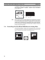
Operating Procedures
1-5
Operating Procedures
Once a function block definition has been created and an instance of the algorithm has been created, the instance is used by calling it when it is time to
execute it. Also, the function block definition that was created can be saved in
a file so that it can be reused in other projects (PLCs).
1-5-1
Creating Function Blocks and Executing Instances
The following procedure outlines the steps required to create and execute a
function block.
1,2,3...
1. First, create the function block definition including the algorithm and variable definitions in ladder program or ST language.
Note (a) Create the algorithm entirely with variable names.
(b) When entering the algorithm in ladder programming language,
project files created with Non-IEC CX-Programmer can be reused
by reading the project file into the CX-Programmer IEC and copying and pasting useful parts.
2. When creating the program, insert copies of the completed function block
definition. This step creates instances of the function block.
3. Enter an instance name for each instance.
4. Set the variables’ input source addresses and/or constants and output
destination addresses and/or constants as the parameters to pass data for
each instance.
5. Select the created instance, select Memory - Function Block Memory
Allocation from the PLC Menu, and set the internal data area for each
type of variable.
6. Transfer the program to the CPU Unit.
7. Start program execution in the CPU Unit and the instance will be called
and executed if their input conditions are ON.
Function block definition A
Program
Input
condition
1. Algorithm
Standard
program section
with variable
names a, b, c,
etc.
Insert in
program.
Input 0.00
The instance is
executed if the input
condition is established.
3. Input instance name
Instance of function block definition A
5. The system automatically allocates
the addresses used by these
variables. Set the data area area in
which these addresses are allocated.
Output 2.00
a
b
c
Output 3.00
2. Variables
Table defining usage
and properties of
variables a, b, c, etc.
4. Specify the input source and
output destination addresses.
21
Section 1-5
Operating Procedures
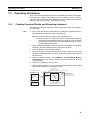
1-5-2
Reusing Function Blocks
Use the following procedure to save a function block definition as a file and
use it in a program for another PLCs.
1,2,3...
1. Select the function block that you want to save and save it as a function
block definition file (*.cxf).
2. Open the other PLC’s project and open/read the function block definition
file (*.cxf) that was saved.
3. Insert the function block definition in the program when creating the new
program.
Function block definition A
Program
1. Algorithm
Input
condition
Standard
program section
with variable
names a, b, c,
etc.
Input 1.00
2. Variables
Table defining usage
and properties of
variables a, b, c, etc.
Instance of function block definition A
a
b
Output 5.00
c
Output 6.00
Read and
insert.
Save
Function
block
definition
A
Function block
definition file (*.cxf)
Note
22
In the CX-Programmer IEC, each function block definition can be compiled
and checked as a program. We recommend compiling to perform a program
check on each function block definition file before saving or reusing the file.
SECTION 2
Creating Function Blocks
This section describes the procedures for creating function blocks on the CX-Programmer IEC.
2-1
2-2
Procedural Flow . . . . . . . . . . . . . . . . . . . . . . . . . . . . . . . . . . . . . . . . . . . . . . .
24
Procedures . . . . . . . . . . . . . . . . . . . . . . . . . . . . . . . . . . . . . . . . . . . . . . . . . . . .
26
2-2-1
Creating a Project . . . . . . . . . . . . . . . . . . . . . . . . . . . . . . . . . . . . . . .
26
2-2-2
Creating a New Function Block Definition . . . . . . . . . . . . . . . . . . .
28
2-2-3
Defining a Function Block . . . . . . . . . . . . . . . . . . . . . . . . . . . . . . . .
29
2-2-4
Creating Instances from Function Block Definitions . . . . . . . . . . . .
36
2-2-5
Setting Function Block Parameters . . . . . . . . . . . . . . . . . . . . . . . . .
38
2-2-6
Setting the FB Instance Areas. . . . . . . . . . . . . . . . . . . . . . . . . . . . . .
39
2-2-7
Checking Internal Address Allocations for Variables . . . . . . . . . . .
40
2-2-8
Checking the Function Block Definition for an Instance . . . . . . . . .
42
2-2-9
Compiling Function Block Definitions . . . . . . . . . . . . . . . . . . . . . .
42
2-2-10 Saving Function Block Definitions to Files . . . . . . . . . . . . . . . . . . .
42
2-2-11 Downloading Programs to a CPU Unit. . . . . . . . . . . . . . . . . . . . . . .
43
2-2-12 Monitoring and Debugging Function Blocks . . . . . . . . . . . . . . . . . .
44
23
Section 2-1
Procedural Flow
2-1
Procedural Flow
The following procedures are used to create function blocks, save them in
files, transfer them to the PLC, monitor them, and debug them.
Creating Function Blocks
Create a Project
Refer to 2-2-1 Creating a Project for details.
■
1,2,3...
Creating a New Project
1. Start the CX-Programmer IEC and select New from the File Menu.
2. Select a Device type with a name ending in “(FB).”
■
1,2,3...
Using a Non-IEC CX-Programmer Project
1. Start the CX-Programmer IEC and read the project file (.cxp) created with
non-IEC CX-Programmer (see note).
Note
The PLC must be the CS1-H, CS1G-H, CJ1H-H, or CJ1G-H.
2. Change the Device type to one with a name ending in “(FB).”
Create a Function Block
Definition
Refer to 2-2-2 Creating a New Function Block Definition for details.
1,2,3...
1. Select Function Blocks in the project workspace and right-click.
2. Select Insert Function Blocks - Ladder or Insert Function Blocks Structured Text from the popup menu.
Define the Function Block
Refer to 2-2-3 Defining a Function Block for details.
■
1,2,3...
Registering Variables before Inputting the Ladder Program or ST Program
1. Register variables in the variable table.
2. Create the ladder program or ST program.
■
1,2,3...
Registering Variables as Necessary while Inputting the Ladder Program
or ST Program
1. Create the ladder program or ST program.
2. Register a variable in the variable table whenever required.
Refer to 2-2-4 Creating Instances from Function Block Definitions for details.
Create an Instance from
the Function Block
Definition
■
1,2,3...
Inserting Instances in the Ladder Section Window and then Inputting the
Instance Name
1. Place the cursor at the location at which to create an instance (i.e., a copy)
of the function block and press the F Key.
2. Input the name of the instance.
3. Select the function block definition to be copied.
■
1,2,3...
Registering Instance Names in the Global Symbol Table and then
Selecting the Instance Name when Inserting
1. Select Function Block as the data type for the variable in the global symbol
table.
2. Press the F Key in the Ladder Section Window.
3. Select the name of the instance that was registered from the pull-down
menu on the Function Block Instance Field.
24
Section 2-1
Procedural Flow
Allocate External I/O to
the Function Block
1,2,3...
Refer to 2-2-5 Setting Function Block Parameters for details.
1. Place the cursor at the position of the input variable or output variable and
press the P Key.
2. Input the source address for the input variable or the destination address
for the output variable.
Set the Function Block
Memory Allocations
(Instance Areas)
1,2,3...
Refer to 2-2-6 Setting the FB Instance Areas for details.
1. Select the instance and select Memory - Function Block Memory Allocation from the PLC Menu.
2. Set the function block memory allocations.
Saving and Reusing Function Block Files
Compile the Function
Block Definition and Save
It as a Library File
1,2,3...
Refer to 2-2-9 Compiling Function Block Definitions and 2-2-10 Saving Function Block Definitions to Files for details.
1. Compile the function block that has been saved.
2. Save the function block as a function block definition file (.cxf).
3. Read the file into another PLC project.
Transferring the Program to the PLC
Refer to 2-2-11 Downloading Programs to a CPU Unit.
Monitoring and Debugging the Function Block
Refer to 2-2-12 Monitoring and Debugging Function Blocks.
25
Section 2-2
Procedures
2-2
2-2-1
Procedures
Creating a Project
Either new projects can be created in CX-Programmer IEC or programs previously requested on non-IEC CX-Programmer can be read to create projects.
Creating New Projects
with CX-Programmer IEC
1,2,3...
1. Start the CX-Programmer IEC and select New from the File Menu.
2. In the Change PLC Window, select a Device Type with a name ending in
“(FB).” These are listed in the following table.
3. Press the Settings Button and select the CPU Type. All other settings are
the same as for non-IEC CX-Programmer.
Device
CS1H-H (FB)
CPU
CPU67
Program size
250 Ksteps
Number of EM banks
13 banks
CS1G-H (FB)
CPU65
CPU44
60 Ksteps
30 Ksteps
3 banks
1 bank
CJ1G-H (FB)
CPU42
CPU44
10 Ksteps
30 Ksteps
1 bank
1 bank
CPU43
CPU42
20 Ksteps
10 Ksteps
1 bank
1 bank
Reusing Projects Created
on Non-IEC CXProgrammer
1,2,3...
1. Start the CX-Programmer IEC, select Open from the File Menu, and read
the project file (.cxp) created with non-IEC CX-Programmer (see note).
Note
The PLC must be the CS1-H, CS1G-H, CJ1H-H, or CJ1G-H.
2. Select the PLC name in the project workspace, right-click, and select
Change from the popup menu.
3. In the Change PLC Window, select a Device Type with a name ending in
“(FB).” These are listed in the following table.
4. Press the Settings Button and select the CPU Type. All other settings are
the same as for non-IEC CX-Programmer.
Device
Note
CPU
Program size
Number of EM banks
CS1H-H (FB)
CPU67
CPU65
250 Ksteps
60 Ksteps
13 banks
3 banks
CS1G-H (FB)
CPU44
CPU42
30 Ksteps
10 Ksteps
1 bank
1 bank
CJ1G-H (FB)
CPU44
CPU43
30 Ksteps
20 Ksteps
1 bank
1 bank
CPU42
10 Ksteps
1 bank
Observe the following precautions when changing the Device type of a project
created with non-IEC CX-Programmer to one that supports function blocks.
(1) Internal Allocations for Variables
If a project file created with the non-IEC CX-Programmer is read and the
Device Type is changed to one that supports function blocks, the default
function block memory allocations (instance area, refer to 2-2-6 Setting
26
Section 2-2
Procedures
the FB Instance Areas) will overlap with any of the following addresses
used in the user program and errors will occur when compiling:
W000 to W511, EM 20480 to EM 32767 in the last EM bank, T1024 to
T4095, and C1024 to C4095.
If addresses are duplicated and an error occurs, either change the function block memory allocations or the addresses used in the user program.
(2) Specifying the Current EM Bank
The CS1-H (FB)/CJ1-H (FB) CPU Units cannot use the current EM bank
function, i.e., the EM bank must always be specified directly. For CPU
Units with model numbers of CPU42, CPU43, and CPU44 there is only
one EM bank, bank 0, which must be specified as E0_1000. For other
CPU Units, which have more than one EM bank, the EMBC(281) instruction must be used as follows to determine the EM bank being used:
Example: EMBC &2
MOV #1111 E1000
Change to the following:
MOV #1111 E2_1000
(3) Timer/Counter PV Refresh Method
The CS1-H (FB)/CJ1-H (FB) CPU Units do not support the BCD refresh
method for timer/counter refresh values. Only the binary refresh method
can be used. If any instructions for the BCD refresh method, such as TIM,
are used in existing programs being reused on the CX-Programmer IEC,
an error will occur and these instructions must be changed to the binary
refresh form. Refer to 6-4 Changing the Timer/Counter PV Refresh Mode
in the Programming Manual for details.
(4) Operation of Timer Instructions with Timer Numbers T2048 to T4095
If the option in the PLC properties to execute T2048 to T4095 timers the
same as other timers is selected after reading the project, timers with
these timer numbers will operate differently in function blocks from the
same timers on the CS1-H or CJ1-H CPU Unit at the following times:
• When the cycle time is over 80 ms
• When one of these timers is in a task placed on standby with the
TKON/TKOFF instructions.
To achieve the same operation as on the CS1-H or CJ1-H CPU Unit, clear
the selection of the option in the PLC properties to execute T2048 to
T4095 timers the same as other timers. Function blocks, however, use
timer numbers T3072 to T4095 by default. Timer instructions with timer
numbers T0000 to T2047 will thus operate differently in the main programs from those in function blocks. To solve this problem and achieve
the same operation, change the timer numbers used by function blocks
to T0000 to T2047. Refer to 3-5-3 Operation of Timer Instructions for details.
27
Section 2-2
Procedures
2-2-2
Creating a New Function Block Definition
1,2,3...
1. When a project is created, a Function Blocks icon will appear in the project
workspace as shown below.
Function Blocks will appear under the PLC.
2. Function blocks are created by inserting function block definitions after the
Function Blocks icon. Function block can be defined using either ladder
programming or structured text.
• Defining Function Blocks with Ladders
Select Function Blocks in the project workspace, right-click, and select
Insert Function Blocks - Ladder from the popup menu. (Or select Function Block - Ladder from the Insert Menu.)
• Defining Function Blocks with Structured Text
Select Function Blocks in the project workspace, right-click, and select
Insert Function Blocks - Structured Text from the popup menu. (Or
select Function Block - Structured Text from the Insert Menu.)
FunctionBlock1 is displayed as the
Icon
under the Function Blocks Icon (
).
3. By default, a function block called FunctionBlock1 will be automatically inserted after the Function Blocks icon. This icon contains the definitions for
the function block.
4. Whenever a function block definition is created, the name FunctionBlock@
will be assigned automatically, where @ is a serial number. These names
can be changed. All names must contain no more than 64 characters.
28
Section 2-2
Procedures
Function Block Definitions
One of the following windows will be displayed when the function block icon is
double-clicked (or if it is right-clicked and Open is selected from the popup
menu). A variable table for the variables used in the function block is displayed
on top and an input area for the ladder program or structured text is displayed
on the bottom.
Ladder Program
Variable table
Ladder input area
Structured Text
Variable table
ST input area
As shown, a function block definition consists of a variable table that serves
as an interface and a ladder program or structured text that serves as an algorithm.
Variable Table as an Interface
At this point, the variable table is empty because there are no variables allocated for I/O memory addresses in the PLC.
Ladder Program or Structure Text as an Algorithm
• With some exceptions, the ladder program for the function block can contain any of the instructions used in the normal program. Refer to 3-3
Restrictions on Function Blocks for restrictions on the instructions that
can be used.
• Structured text can be input according to the ST language defined in
IEC61131-3.
2-2-3
Defining a Function Block
A function block is defined by registering variables and creating an algorithm.
There are two ways to do this.
• Register the variables first and then input the ladder program or structure
text.
• Register variables as they are required while inputting input the ladder
program or structure text.
29
Section 2-2
Procedures
Registering Variables First
Registering Variables in
the Variable Table
The variables are divided by type into four sheets in the variable table: Internals, Inputs, Outputs, and Externals.
These sheets must be switched while registering or displaying the variables.
1,2,3...
1. Make the sheet for the type of variable to be registered active in the variable table. (See note.) Place the cursor in the sheet, right-click, and select
Insert Variable from the popup menu.
Note
The sheet where a variable is registered can also be switched by
setting the Usage.
The New Variable Dialog Box shown below will be displayed.
• Name: Input the name of the variable.
• Data Type: Select the data type.
• Usage: Select the variable type.
• Initial Value: Select the initial value of the variable at the start of operation.
• Retain: Select if the value of the variable is to be maintained when the
power is turned ON or when the operating mode is changed from
PROGRAM or MONITOR mode to RUN mode. The value will be
cleared at these times if Retain is not selected.
Input the name of the
function block variable The default data type is BOOL.
Change as required.
Type of variable to register
(i.e., the sheet)
Initial value
Select to maintain value for
power interruptions.
2. For example, input “aaa” as the variable name and click the OK Button.
As shown below, a BOOL variable called aaa will be created on the Inputs
Sheet of the Variable Table.
BOOL variable called aaa
created on Inputs Sheet.
30
Section 2-2
Procedures
Creating the Algorithm
1,2,3...
Using a Ladder Program
1. Press the C Key and select aaa registered earlier from the pull-down menu
in the New Contact Dialog Box.
Press the C Key and select aaa registered earlier
from the pull-down menu in the New Contact Dialog Box.
Note
A name must be input for variables, even ones with AT settings
(specified address). With CX-Programmer IEC, the following characters can be input as the variable name to indicate I/O memory
addresses. (This is not possible with non-IEC CX-Programmer.)
• A, W, H, HR, D, DM, E, EM, T,TM, C, or CNT followed by a number
(channel/word address)
• A period to differentiate between channel (word) and bit addresses.
For example, when Auxiliary Area addresses are specified as ATs, the
I/O memory address (e.g., A50200) can be specified as the variable
name to make assignments easier to understand. (Even when this is
done, the actual address must be specified in the AT settings.)
2. Click the OK Button. A contact will be entered with the function block internal variable aaa as the operand (variable type: internal).
Contact entered with function block
internal variable aaa as operand.
The rest of the ladder program is input the same as for normal programs with
non-IEC CX-Programmer.
31
Section 2-2
Procedures
Using Structured Text
An ST language program (see note) can either be input directly into the ST
input area or a program input into a general-purpose text editor can be copied
and then pasted into the ST input area using the Paste Command on the Edit
Menu.
Note
The ST language conforms to IEC61131-3, but only assignment statements,
selection statements (CASE and IF), iteration statements (FOR, WHILE, and
REPEAT), arithmetic operations, logic operations, comparison operations,
and comments. All other elements are not supported. Refer to Appendix B
Structured Text Keywords for details.
ST program input directly or pasted from one
created in a text editor.
Note
(1) Tabs or spaces can be input to create indents. They will not affect the algorithm.
(2) The display size can be changed by holding down the Ctrl Key and turning the scrolling wheel on a wheel mouse.
(3) When an ST language program is input or pasted into the ST input area,
syntax keywords will be automatically displayed in blue, errors in red,
comments in green, and everything else in black.
(4) To change the font size or colors, select Options from the Tools Menu
and then click the ST Font Button on the Appearance Tab Page.
Click the ST Font Button
to change the font.
32
Section 2-2
Procedures
Registering Variables as Required
The ladder program or structured text program can be input first and variable
registered as they are required.
Using a Ladder Program
When using a ladder diagram, a dialog box will be displayed to register the
variable whenever a variable name that has not been registered is input. The
variable is registered at that time.
Use the following procedure.
1,2,3...
1. Press the C Key and input a variable name that has not been registered,
such as aaa, in the New Contact Dialog Box.
Note
A name must be input for variables, even ones with AT settings
(specified address). With CX-Programmer IEC, the following characters can be input as the variable name to indicate I/O memory
addresses. (This is not possible with non-IEC CX-Programmer.)
• A, W, H, HR, D, DM, E, EM, T,TM, C, or CNT followed by a number
(channel/word address)
• A period to differentiate between channel (word) and bit addresses.
For example, when Auxiliary Area addresses are specified as ATs, the
I/O memory address (e.g., A50200) can be specified as the variable
name to make assignments easier to understand. (Even when this is
done, the actual address must be specified in the AT settings.)
2. Click the OK Button. The New Variable Dialog Box will be displayed. With
special instructions, a New Variable Dialog Box will be display for each operand in the instruction.
Set the data type and other
properties other than the name.
The properties for all input variables will initially be displayed as follows:
• Usage: Internal
• Data Type: BOOL for contacts and WORD for channel (word)
• Initial Value: The default for the data type.
• Retain: Not selected.
3. Make any required changes and click the OK Button.
4. As shown below, the variable that was registered will be displayed in the
variable table above the program.
Instruction input. Function block internal variable registered.
5. If the type or properties of a variable that was input are not correct, doubleclick the variable in the variable table and make the required corrections.
33
Section 2-2
Procedures
■ Reference Information
AT Settings (Specified Address)
AT settings can be made to specify CIO or DM Area addresses allocated to a
Special I/O Unit or Auxiliary Area addresses not registered in the CX-Programmer IEC. A variable name is required to achieve this. Use the following
procedure to specify an address.
1,2,3...
1. After inputting the variable name in the New Variable Dialog Box, click the
Advanced Button. The Advanced Settings Dialog Box will be displayed.
2. Select AT (Specified Address) under AT Settings and input the desired address.
Select AT.
Input address.
The variable name is used to enter variables into the algorithm in the function block definition even when they have an address specified for the AT
settings (the same as for variables without a specified address).
For example, if a variable named Restart has an address of A50100 specified for the AT settings, Restart is specified for the instruction operand.
Array Settings
An array can be specified to use the same data properties for more than one
variable and manage the variables as a group.
Use the following procedure to set an array.
1,2,3...
1. After inputting the variable name in the New Variable Dialog Box, click the
Advanced Button. The Advanced Settings Dialog Box will be displayed.
2. Select Array Variable in the Array Settings and input the maximum number
of elements in the array.
Select Array Variable.
Input the number of elements.
When the name of a variable array is entered in the algorithm in the function block definition, square brackets surrounding the index will appear after the array name.
For example, if you create a variable named PV with a maximum of 3 elements, PV[0], PV[1], and PV[2] could be specified as instruction operands.
There are three ways to specify indices.
• Directly with numbers, e.g., PV[1] in the above example (for ladder programming or ST language programming)
34
Section 2-2
Procedures
• With a variable, e.g., PV[a] in the above example, where “a” is the
name of a variable with a data type of INT (for ladder programming or
ST language programming)
• With an equation, e.g., PV[a+b] or PV[a+1} in the above example,
where “a” and “b” are the names of variables with a data type of INT
(for ST language programming only)
Using an Array to Specify Words Allocated to CPU Bus Units
The first DM Area word allocated to a CS-series or CJ-series CPU Bus Unit is
expressed by the following formula:
D30000 + unit number × 100
Thus an array variable can be used to indirectly address DM Area words allocated to CPU Bus Units by using a formula containing the unit number as an
index to the array.
For example, the following could be done if the unit number is given by the
variable named N and the variable named DataMemory is an array variable
for the DM Area words allocated to the CPU Bus Unit.
1,2,3...
1. Register the variable DataMemory as an array variable with a maximum of
1,600 elements.
2. To designate the DM Area word that is s words from the first allocated word
(where s is either a variable or a direct offset in number of words), the following variable would be used and the AT setting for the Data Memory variable would be set to D30000.
DataMemory[N*100+s]
3. The function block definition would then be placed in the program and
words allocated to the CPU Bus Unit could be specified merely by passing
the unit number (using N in the above example) to the instance. For example, if a value of 5 was passed for N, D30500 would be specified.
35
Section 2-2
Procedures
Reusing Non-IEC CX-Programmer Projects (.cxp)
1,2,3...
1. Read the non-IEC CX-Programmer project (.cxp) and change the Device
Type to one that supports function blocks.
2. Cut the rungs to be used in the function block.
3. Create a new function block definition.
4. Paste the rungs into the function block.
1. Open non-IEC CX-Programmer project and change
Device Type to one that supports function blocks.
2. Cut for use in function block.
3. Create function block definition.
4. Paste into function block.
5. Symbols used in non-IEC CX-Programmer
automatically registered as FB variables.
5. When the rungs are pasted, any symbols used in non-IEC CX-Programmer will automatically be registered in the variable table of the function
block. Any addresses that were specified directly in non-IEC CX-Programmer will be displayed in red and nothing will be registered for them. Change
all of these to variables.
Using Structured Text
2-2-4
When using structured text, a dialog box will not be displayed to register the
variable whenever a variable name that has not been registered is input. Be
sure to always register variables used in standard text programming in the
variable table, either as you need them or after completing the program.
(Place the cursor in the tab page on which to register the variable, right-click,
and select Insert Variable from the popup menu.
Creating Instances from Function Block Definitions
If a function block definition is registered in the global symbol table, either of
the following methods can be used to create instances.
Method 1:Select the function block definition, insert it into the program, and
input a new instance name. The instance will automatically be registered in
the global symbol table.
Method 2: Set the data type in the global symbol table to “function block,”
specify the function block definition to use, and input the instance name to
register it.
36
Section 2-2
Procedures
■ Method 1: Using the F Key in the Ladder Section Window and Inputting
the Instance Name
1,2,3...
1. In the Ladder Section Window, place the cursor in the program where the
instance is to be inserted and press the F Key. (Alternately, select Function Block Invocation from the Insert Menu.) The New Function Block Invocation Dialog Box will be displayed.
2. Input the instance name, select the function block from which to create an
instance, and click the OK Button.
Press F Key with cursor here.
Following dialog Input the instance name.
box is displayed.
Select the function block
from which to create an
3. As an example, set the instance name in the FB Instance Field to sample,
set the function block in the FB Definition Field to FunctionBlock1, and
click the OK Button. As shown below, a copy of the function block definition
called FunctionBlock1 will be created with an instance name of sample.
Instance name
Function block definition
An instance called sample
is created from the function
block definition called
FunctionBlock1.
The instance will be automatically registered in the global symbol table
with an instance name of sample and a data type of Function block.
■ Method 2: Registering the Instance Name in the Global Symbol Table in
Advance and Then Selecting the Instance Name
If the instance name is registered in the global symbol table in advance, the
instance name can be selected from the global symbol table to create other
instances.
1,2,3...
1. Select a data type of Function block in the global symbol table, input the
instance name, and registered the instance.
2. Press the F Key in the Ladder Section Window. The Function Block Invocation Dialog Box will be displayed.
3. Select the instance name that was previously registered from the pulldown
menu on the FB Instance Field. The instance will be created.
37
Section 2-2
Procedures
Restrictions
Observe the following restrictions when creating instances. Refer to 3-3
Restrictions on Function Blocks for details.
• No more than one function block can be created in each program circuit.
• The rung cannot be branched to the left of an instance.
• Instances cannot be connected directly to the left bus bar, i.e., an EN
must always be inserted.
Note
2-2-5
If changes are made in the I/O variables in a variable table for a function block
definition, the bus bar to the left of all instances that have been created from
that function block definition will be displayed in red to indicate an error. When
this happens, select each instance, right-click, and select Update Invocation.
The instance will be updated for any changes that have been made in the
function block definition and the red display will be cleared.
Setting Function Block Parameters
After an instance of a function block has been created, input parameters must
be set for input variables and output parameters must be set for output variables to enable external I/O.
1,2,3...
1. Inputs are located on the left of the instance and outputs on the right. Place
the cursor where the parameter is to be set and press the P Key. (Alternately, select Function Block Parameter from the Insert Menu.) The New
Parameter Dialog Box will be displayed as shown below.
Instance name
Function block definition
Press the P Key with the cursor on the left
of the instance. The New Parameter
Dialog Box will be displayed.
Input the address from which to pass data
to the input variable.
38
Section 2-2
Procedures
2. Input the address from which to pass status data to the input variable.
The value of 001 is passed to input
variable aaa.
3. Input the addresses from/to which to pass data for the other input and output variables.
2-2-6
Setting the FB Instance Areas
The areas where addresses for variables used in function blocks are allocated
can be set. These areas are called the function block instance areas.
1,2,3...
1. Select the instance in the Ladder Section Window or in the global symbol
table, and then select Memory - Function Block Memory Allocation
from the PLC Menu.
The Function Block Memory Allocation Dialog shown below will appear.
2. Set the FB instance areas.
Non-retained area
Retained area
Timer area
Counter area
First
address
Last
address
Size
The non-retained and retained areas are set in words. The timer and
counter areas are set by time and counter numbers.
The default values are as follows:
FB instance area
Start address
End
address
512
Non-retained area
W0
Retained area
12,288
Timer area
E0_20480
(See note a.)
T3072
1,024
Applicable memory
areas
CIO, WR, HR, DM, EM
(See note b.)
HR, DM, EM
(See note b.)
TIM
Counter area
C3072
1,024
CNT
Note (a) E20480 to E32767 in the last EM Area bank is the default setting.
The number of the last EM Area bank depends on the model of
CPU Unit being used.
(b) Bit data can be accessed even if the DM or EM Area is specified.
39
Section 2-2
Procedures
Note
Overlapping of Instance Area Addresses and Address Used in the Program
If the addresses in the function block instance areas overlap with any of the
addresses used in the user program, an error will occur when compiling. This
error will also occur when a program is downloaded, edited online, or checked
by the user.
Work Area Addresses
used in the user
program overlap with
the instance areas.
If addresses are duplicated and an error occurs, either change the function
block instance areas or the addresses used in the user program.
2-2-7
Checking Internal Address Allocations for Variables
The following procedure can be used to check the I/O memory addresses
internally allocated to variables.
1,2,3...
1. Select View - Symbols - Global.
2. Select the instance in the global symbol table, right-click, and select Function Block Memory Address from the popup menu. (Alternately, select
Memory - Function Block Memory Address from the PLC Menu.)
Example: Instance name displayed in global variable table (automatically registered)
Right-click on the instance name and select Function Block Instance Address.
3. The FB Interface Memory Dialog Box will be displayed. Check the I/O
memory addresses internally allocated to variables here.
Example: Addresses used internally
for the input variables.
40
Section 2-2
Procedures
Method Used for Checking Addresses Internally Allocated to Variables
Program
Instance of function block definition A,
instance name: sample
a
b
c
Instance registered in global
symbol table under instance name.
Name Type
sample FB [FunctionBlock1]
Right-click and select Function
Block Memory Address.
FM Instance Memory Dialog Box
Address/
Value
N/A [Auto]
Instance name
Inputs
Name Type
a
BOOL
Address
W400.00
Outputs
Name Type
b
BOOL
c
BOOL
Address
W401.00
W401.02
Addresses used for function
block internal variables
Checking the Status of
Addresses Internally
Allocated to Variables
1,2,3...
The following procedure can be used to check the number of addresses allocated to variables and the number still available for allocation in the function
block instance areas.
1. Select the instance in the Ladder Section Window, right-click, and select
Memory - Function Block Memory Statistics from the PLC Menu.
2. The Function Block Memory Statistics Dialog Box will be displayed as
shown below. Check address usage here.
The total number
The number of
of words in each The number words still available.
interface area. of words
already used.
Optimizing Function
Memory
1,2,3...
When a variable is added or deleted, addresses are automatically re-allocated
in the variables’ instance area. Consecutive addresses are required for each
instance, so all of the variables will be allocated to a different block of
addresses if the original block of addresses cannot accommodate the change
in variables. This will result in an unused block of addresses. The following
procedure can be used to eliminate the unused areas in memory so that
memory is used more efficiently.
1. Select the instance in the Ladder Section Window, right-click, and select
Memory - Optimize Function Memory from the PLC Menu.
The following dialog box will be displayed.
2. Click the OK Button. Allocations to the function block instance areas will
be optimized.
41
Section 2-2
Procedures
2-2-8
Checking the Function Block Definition for an Instance
Use the following procedure to check the function block definition from which
an instance was created.
1,2,3...
2-2-9
Right-click the instance and select Go To - Function Block Definition from
the popup menu. The function block definition will be displayed.
Compiling Function Block Definitions
A function block definition can be compiled to perform a program check on it.
Use the following procedure.
1,2,3...
Select the function block definition, right-click, and select Compile from the
popup menu. (Alternately, press the Ctrl + F7 Keys.)
The function block will be compiled and the results of the program check will
be automatically displayed on the Compile Table Page of the Output Window.
Results of program check displayed.
2-2-10 Saving Function Block Definitions to Files
A function block definition can be saved as a function block library file (extension: .cxf) to enable reusing it in other projects.
Saving a Function Block
Library File
1,2,3...
42
Use the following procedure to save a function block definition to a function
block library file.
1. Select the function block definition, right-click, and select Save Function
Block File from the popup menu. (Alternately, select Save Function
Block File from the File Menu.)
Section 2-2
Procedures
2. The following dialog box will be displayed. Input the file name. CX-P IEC
function block library files (*.cxf) should be selected as the file type.
Reading Function Block
Library Files into Other
Projects
1,2,3...
Use the following procedure to read a function block library file (*.cxf) into a
project.
1. Select the function block definition item in the Project Workspace, rightclick, and select Insert Function Block - From File from the popup menu.
2. The following dialog box will be displayed. Select a function block library
file (*.cxf) and click the Open Button.
3. A function block called FunctionBlock1 will be automatically inserted after
the Function Blocks icon. This icon contains the definition of the function
block.
4. Double-click the FunctionBlock1 Icon. The variable table and algorithm
will be display.
2-2-11 Downloading Programs to a CPU Unit
After a program containing function blocks has been created, it can be downloaded from the CX-Programmer IEC to a CPU Unit that is connected online.
It is also possible to check if the programs on the CX-Programmer IEC and in
the CPU Unit are the same.
Programs cannot be uploaded from the CPU Unit.
43
Section 2-2
Procedures
2-2-12 Monitoring and Debugging Function Blocks
The following procedures can be used to monitor programs containing function blocks.
Monitoring Programs in
Function Block Definitions
Use the following procedure to check the program in the function block definition for an instance during monitoring.
1,2,3...
Right-click the instance and select Go To - Function Block Definition from
the popup menu. The function block definition will be displayed.
Monitoring Instance
Variables in the Watch
Window
1,2,3...
Use the following procedure to monitor instance variables.
1. Select View - Window - Watch.
A Watch Window will be displayed.
2. Double-click the watch window.
The Edit Dialog Box will be displayed as shown below.
Click the Browse Button.
3. Click the Browse Button, select the variable to be monitored, and click the
OK Button.
Select the variable to monitor.
4. Click the OK Button. Variable values will be display in the Watch Window
as shown below.
Address being used
Variable name
44
Section 2-2
Procedures
Monitoring Instance I/O
Variables
The present values of parameters for I/O variables are displayed below the
parameters.
PV of parameter for I/O variable.
Editing Function Block
Definition Programs
Online
Programs using function blocks can be edited online. Changes can also be
made around instances.
• Instance parameters can be changed, instances can be deleted, and
instructions other than those in instances can be changed.
• Instances cannot be added, instance names cannot be changed, and
algorithms and variable tables in function block definitions cannot be
changed.
45
Procedures
46
Section 2-2
SECTION 3
Specifications
This section provides specifications for reference when using function blocks, including specifications on function blocks,
instances, and compatible PLCs, as well as usage precautions and guidelines.
3-1
3-2
Function Block Specifications . . . . . . . . . . . . . . . . . . . . . . . . . . . . . . . . . . . .
48
3-1-1
Function Block Specifications . . . . . . . . . . . . . . . . . . . . . . . . . . . . .
48
3-1-2
Function Block Elements . . . . . . . . . . . . . . . . . . . . . . . . . . . . . . . . .
48
Instance Specifications . . . . . . . . . . . . . . . . . . . . . . . . . . . . . . . . . . . . . . . . . .
57
3-2-1
Composition of an Instance . . . . . . . . . . . . . . . . . . . . . . . . . . . . . . .
57
3-2-2
Operating Specifications. . . . . . . . . . . . . . . . . . . . . . . . . . . . . . . . . .
59
3-3
Restrictions on Function Blocks . . . . . . . . . . . . . . . . . . . . . . . . . . . . . . . . . . .
60
3-4
Function Block Applications Guidelines . . . . . . . . . . . . . . . . . . . . . . . . . . . .
65
3-4-1
Deciding on Variable Data Types . . . . . . . . . . . . . . . . . . . . . . . . . . .
65
3-4-2
Array Settings . . . . . . . . . . . . . . . . . . . . . . . . . . . . . . . . . . . . . . . . . .
65
3-4-3
AT Settings . . . . . . . . . . . . . . . . . . . . . . . . . . . . . . . . . . . . . . . . . . . .
66
CPU Unit Specifications and Battery Replacement . . . . . . . . . . . . . . . . . . . .
67
3-5-1
Specifications . . . . . . . . . . . . . . . . . . . . . . . . . . . . . . . . . . . . . . . . . .
67
3-5-2
General Specifications . . . . . . . . . . . . . . . . . . . . . . . . . . . . . . . . . . .
75
3-5-3
Operation of Timer Instructions . . . . . . . . . . . . . . . . . . . . . . . . . . . .
78
3-5-4
Battery Replacement Procedure . . . . . . . . . . . . . . . . . . . . . . . . . . . .
79
3-5
47
Section 3-1
Function Block Specifications
3-1
3-1-1
Function Block Specifications
Function Block Specifications
Item
Description
Number of function block definitions 896 max. per CPU Unit
3-1-2
Number of instances
Number of instance nesting levels
2,048 max. per CPU Unit
Nesting is not supported.
Number of I/O variables
64 variables max. per function block definition
Function Block Elements
The following table shows the items that must be entered by the user when
defining function blocks.
Function Block
Definition Name
Item
Function block
definition name
Description
The name of the function block definition
Language
The programming language used in the function block definition. Select ladder programming or structured text
Variable definitions
Variable settings, such as operands and return values,
required when the function block is executed
• Type (usage) of the variable
• Name of the variable
• Data type of the variable
• Initial value of the variable
Algorithm
Comment
Enter the programming logic in ladder or structured text.
Function blocks can have comments.
Each function block definition has a name. The names can be up to 64 characters long and there are no prohibited characters. The default function block
name is FunctionBlock@, where @ is a serial number.
Function block definition name
CLOCK PULSE
EN
ENO
(BOOL) (BOOL)
ON_TIME
(INT)
OFF_TIME
(INT)
Language
Select either ladder or structured text.
Variable Definitions
Define the operands and variables used in the function block definition.
Variable Names
• Variable names can be up to 30,000 characters long.
• Variables name cannot contain spaces or any of the following characters:
! “ # $ % & ‘ ( ) = - ~ ^ \ | ‘ @ { [ + ; * : } ] < , > . ? /
• Variable names cannot start with a number (0 to 9).
• Variable names cannot contain two underscore characters in a row.
There are no other restrictions.
48
Section 3-1
Function Block Specifications
Variable Notation
CLOCK PULSE
EN
ENO
(BOOL) (BOOL)
ON_TIME
(INT)
OFF_TIME
(INT)
Variable table
Usage
Internal
Internal
Input
Input
Name
tim_a
tim_b
ON_TIME
OFF_TIME
Type
TIMER
TIMER
INT
INT
Output variables
Input variables
tim_b
TIMX tim_a OFF_TIME
tim_a
TIMX tim_b OFF_TIME
ENO
Internal
variables
Variable Type (Usage)
Item
Variable type
Outputs
Internals
Return values from the Variables used only
instance
within instance
Externals
Global symbols registered as variables
beforehand with the
CX-Programmer IEC
Status of value at next The value is not
execution
passed on to the next
execution.
Display
Displayed on the left
side of the instance.
The value is passed
on to the next execution.
Displayed on the right
side of the instance.
The value is not
passed on to the next
execution.
Not displayed.
Number allowed
64 max. per function
block (excluding EN)
64 max. per function
Unlimited
block (excluding ENO)
Reserved variables
only (28 total)
AT setting
Array setting
No
No
No
No
Supported
Supported
No
No
Retain setting
Variables created by
default
No
EN (Enable):
Receives an input condition.
Supported
ENO (Enable Output):
Outputs the function
block’s execution status.
Supported
None
No
Global symbols registered in advance as
variables in the CXProgrammer IEC, such
as Condition Flags and
some Auxiliary Area
bits.
Definition
Inputs
Operands to the
instance
Note
The value is passed
on to the next execution.
Not displayed.
For details on Externals, refer to Appendix C External Variables.
■ Input Variables
Input variables pass external operands to the instance. The input variables
are displayed on the left side of the instance.
The value of the input source (data contained in the specified parameter just
before the instance was called) will be passed to the input variable.
P_On
D0
1.0
FB
EN
ENO
PV
D100
CV
The value of the parameter specified as the input (value of D0)
is passed to the instance’s input variable (PV).
49
Section 3-1
Function Block Specifications
Example
0.0
ADD_INT_DINT
EN
ENO
D100
IN16
OUT32
10.0
Algorithm (Body)
P_On
SIGN IN16
+L IN32
D200
tmp OUT32
IN32
IN16 is an INT variable, so the content of D100 is used.
IN32 is a DINT variable, so the content of D200 and
D201 is used.
Note
tmp
D1000
Variable table
Usage
Name
Internal tmp
EN
Input
IN16
Input
IN32
Input
Output ENO
Output OUT32
Type
DINT
BOOL
INT
DINT
BOOL
DINT
1. The same name cannot be assigned to an input variable and output variable. If it is necessary to have the same variable as an input variable and
output variable, register the variables with different names and transfer the
value of the input variable to the output variable in the function block with
an instruction such as MOV.
2. When the instance is executed, input values are passed from parameters
to input variables before the algorithm is processed. Consequently, values
cannot be read from parameters to input variables within the algorithm. If
it is necessary to read a value within the execution cycle of the algorithm,
do not pass the value from a parameter. Assign the value to an internal
variable and use an AT setting (specified addresses).
Initial Value
When you set an initial value for an input variable, that value will be written to
the variable when the parameter for input variable EN goes ON and the
instance is executed for the first time (and that one time only). If an initial
value has not been set for an input variable, the input variable will be set to 0
when the instance is first executed.
EN (Enable) Variable
When an input variable is created, the default input variable is the EN variable. The instance will be executed when the parameter for input variable EN
is ON.
■ Output Variables
Output variables pass return values from the instance to external applications.
The output variables are displayed on the right side of the instance.
After the instance is executed, the value of the output variable is passed to
the specified parameter.
P_On
EN
D0
PV
FB
ENO
CV
1.0
D100
The value of the output variable (CV) is passed to the parameter
specified as the output destination, which is D100 in this case.
50
Section 3-1
Function Block Specifications
Example
0.0
ADD_INT_DINT
EN
ENO
D100
IN16
D200
OUT32
Algorithm (Body)
10.0
EN
SIGN IN16 tmp
D1000
+L IN32
IN32
Variable table
Usage
Name
Internal tmp
EN
Input
IN16
Input
IN32
Input
Output ENO
Output OUT32
OUT32 is a DINT variable, so
the variable's value is passed
to D1000 and D1001.
tmp OUT32
Type
DINT
BOOL
INT
DINT
BOOL
DINT
Like internal variables, the values of output variables are retained until the
next time the instance is executed.
Example:
In the following example, the value of output variable CV will be retained until
the next time the instance is executed.
Product A counter
CTD
CD
Q
LD
PV
Note
CV
D150
1. The same name cannot be assigned to an input variable and output variable. If it is necessary to have the same variable as an input variable and
output variable, register the variables with different names and transfer the
value of the input variable to the output variable in the function block with
an instruction such as MOV.
2. When the instance is executed, output variables are passed to the corresponding parameters after the algorithm is processed. Consequently, values cannot be written from output variables to parameters within the
algorithm. If it is necessary to write a value within the execution cycle of the
algorithm, do not write the value to a parameter. Assign the value to an internal variable and use an AT setting (specified addresses).
Initial Value
An initial value can be set for an output variable that is not being retained, i.e.,
when the Retain Option is not selected. An initial value cannot be set for an
output variable if the Retain Option is selected.
The initial value will not be written to the output variable if the IOM Hold Bit
(A50012) is ON.
Auxiliary Area control bit
IOM Hold Bit (A50012)
ON
Initial value
The initial value will not be set.
ENO (Enable Output) Variable
The ENO variable is created as the default output variable. The ENO output
variable will be turned ON when the instance is called. The user can change
this value. The ENO output variable can be used as a flag to check whether or
not instance execution has been completed normally.
51
Section 3-1
Function Block Specifications
■ Internal Variables
Internal variables are used within an instance. These variables are internal to
each instance. They cannot be referenced from outside of the instance and
are not displayed in the instance.
The values of internal variables are retained until the next time the instance is
executed. Consequently, even if instances of the same function block definition are executed with the same I/O parameters, the result will not necessarily
be the same.
Example:
The internal variable tim_a in instance Pulse_2sON_1sOFF is different from
internal variable tim_a in instance Pulse_4sON_1sOFF, so the instances cannot reference and will not affect each other’s tim_a value.
Variable table
Name
Usage
Internal tim_a
Internal tim_b
ON_TIME
Input
OFF_TIME
Input
Pulse_2sON_1sOFF
P_On
CLOCK PULSE
EN
ENO
1.0
&20
ON_TIME
&10
Type
TIMER
TIMER
INT
INT
OFF_TIME
Pulse_4sON_1sOFF
P_On
CLOCK PULSE
EN
ENO
1.1
&40
ON_TIME
&10
0.0
OFF_TIME
ADD_INT_DINT
EN
ENO
D100
IN16
D200
OUT32
10.0
Algorithm (Body)
EN
SIGN IN16 tmp
D1000
+L IN32
IN32
Internal variable tmp
is not displayed.
tmp OUT32
Variable table
Name
Internal tmp
EN
Input
IN16
Input
IN32
Input
Output ENO
Output OUT32
Type
DINT
BOOL
INT
DINT
BOOL
DINT
Retain Data through Power Interruptions and Start of Operation
Internal variables retain the value from the last time that the instance was
called. In addition, the Retain Option can be selected so that an internal variable will also retains its value when the power is interrupted or operation
starts (the mode is switched from PROGRAM to RUN or MONITOR mode).
When the Retain Option is selected, the value of the variable is retained when
the power is interrupted or operation starts unless the CPU Unit does not
have a backup battery. If the CPU Unit does not have a good battery, the
value will be unstable.
Variables
Variables set to Retain
52
Condition
Start of operation
Power ON
Status
Retained
Retained
Section 3-1
Function Block Specifications
When the Retain Option is not selected, the value of the variable will not be
held when the power is interrupted or operation starts. Even variables not set
to be retained, however, can be held at the start of operation by turning ON
the IOM Hold Bit (A50012) and can be held during power interruptions by setting the PLC Setup, as shown in the following table.
Variables
Condition
IOM Hold Bit (A50012) setting
ON
OFF
Variables not
set to Retain
Start of operation Not retained
IOM Hold Bit Status at Startup
(PLC Setup) selected
Retained
IOM Hold Bit Status at Startup
(PLC Setup) not selected
Retained
Power ON
Retained
Not retained
Note
Not retained
The IOM Hold Bit (A50012) is supported for compatibility with previous models. To hold the values of variables in function blocks, however, use the Retain
Option and not the IOM Hold Bit.
Initial Value
An initial value can be set for an internal variable that is not being retained
(i.e., when the Retain Option not selected). An initial value cannot be set for
an internal variable if the Retain Option is selected.
Internal variables that are not being retained will be initialized to 0.
The initial value will not be written to the internal variable if the IOM Hold Bit
(A50012) is ON.
Auxiliary Area control bit
IOM Hold Bit (A50012)
ON
OFF
Initial value
The initial value will not be set.
The initial value will be set.
■ External Variables
External variables are global symbols registered as variables in advance with
the CX-Programmer IEC. For details, refer to Appendix C External Variables.
Variable Properties
Variable Name
The variable name is used to identify the variable in the function block. The
name can be up to 30,000 characters long. The same name can be used in
other function blocks.
Note
A variable name must be input for variables, even ones with AT settings
(specified address).
53
Section 3-1
Function Block Specifications
Data Type
Any of the following types may be used.
Data type
BOOL
Content
OK
Outputs
OK
Internals
OK
Bit data
1 bit
INT
UNIT
Integer
Unsigned integer
16 bits
16 bits
OK
OK
OK
OK
OK
OK
DINT
UDINT
Double integer
Unsigned double integer
32 bits
32 bits
OK
OK
OK
OK
OK
OK
LINT
ULINT
Long (8-byte) integer
Unsigned long (8-byte) integer
64 bits
64 bits
OK
OK
OK
OK
OK
OK
WORD
DWORD
16-bit data
32-bit data
16 bits
32 bits
OK
OK
OK
OK
OK
OK
LWORD
REAL
64-bit data
Real number
64 bits
32 bits
OK
OK
OK
OK
OK
OK
LREAL
TIMER
Long real number
Timer (See note.)
64 bits
Flag: 1 bit
PV: 16 bits
OK
OK
OK
OK
OK
OK
COUNTER
Counter (See note.)
Flag: 1 bit
PV: 16 bits
OK
OK
OK
Note
Size
Inputs
The TIMER and COUNTER data types cannot be used in ST language function blocks.
AT Settings (Allocation to Actual Addresses)
With internal variables, it is possible to set the variable to a particular I/O
memory address rather than having it allocated automatically by the system.
To specify a particular address, the user can input the desired I/O memory
address in this property. It is still necessary to use variable name in programming even if a particular address is specified.
Note
The AT property can be set for internal variables only.
Example:
If the READ DATA FILE instruction (FREAD) is being used in the function
block definition and it is necessary to check the File Memory Operation Flag
(A34313), use an internal variable and specify the flag’s address in the AT
setting.
Register an internal variable, select the AT setting option, and specify A34313
as the address. The status of the File Memory Operation Flag can be checked
through this internal variable.
Address A34313 is allocated to a
boolean internal variable named
NOW_CARD_ACCESS.
When the AT setting is used, the function block loses its flexibility. This function should thus be used only when necessary.
54
Section 3-1
Function Block Specifications
Array Setting
With internal variables, a variable can be defined as an array.
Note
Only one-dimensional arrays are supported by the CX-Programmer IEC.
With the array setting, a large number of variables with the same properties
can be used by registering just one variable.
• An array can have from 1 to 32,000 array elements.
• The array setting can be set for internal variables only.
• Any data type can be specified for an array variable, as long as it is an
internal variable.
• When entering an array variable name in the algorithm of a function block
definition, enter the array index number in square brackets after the variable name. The following three methods can be used to specify the index.
(In this case the array variable is a[].)
• Directly with numbers (for ladder or ST language programming)
Example: a[2]
• With a variable (for ladder or ST language programming)
Example: a[n], where n is a variable
• With an equation (for ST language programming only)
Example: a[b+c], where b and c are variables
Note
Equations can contain only arithmetic operators (+, −, *, and /).
An array is a collection of data elements that are the same type of data. Each
array element is specified with the same variable name and a unique index.
(The index indicates the location of the element in the array.)
A one-dimensional array is an array with just one index number.
Example: When an internal variable named SCL is set as an array variable
with 10 elements, the following 10 variables can be used:
SCL[0], SCL[1], SCL[2], SCL[3], SCL[4], SCL[5], SCL[6], SCL[7], SCL[8], and
SCL[9]
SCL
0
1
2
3
4
5
6
7
8
9
WORD variable
WORD variable
WORD variable
WORD variable
WORD variable
WORD variable
WORD variable
WORD variable
WORD variable
WORD variable
Specify SCL[3] to access this data element.
Settings for variable SCL as an array
variable with element numbers 0 to 9.
Note
When specifying the first or last word of multiple words for an instruction operand, I/O parameters cannot be used to pass data to or from I/O variables.
Internal array variables must be used. This applies, for example, to the first
source word for SEND(090) or the starting word or end word for BSET(071).
55
Section 3-1
Function Block Specifications
For multiword operands, an array variable must be prepared in advance with
the required number of elements and the data must be set for the array in the
function block definition. The first or last element in the array variable is then
specified for the operand to set the first or last word. Refer to 3-4 Function
Block Applications Guidelines for details.
Example:
Function block definition
Instance
SCL
Variable
SCL
EN
WORD[10]
S
ENO
D
100
Algorithm
SCL- BODY
SCL
LD P_On
MOV #0000 SC
SCL[0]
MOV &0SCL[1]
SC
SCL[2]
MOV #0300 SC
MOV &4000 SCL[3]
SC
SCL S SCL[0]
SC
D
0
1
2
3
#0000
&0
#0300
&4000
Specifying this array element
in the SCL instruction is the
same as specifying the first
address.
Write the operand data to
the array variables.
Specify the beginning of the
array in the SCL instruction.
Note
For details, refer to 3-4 Function Block Applications Guidelines.
Initial Values
When an instance is executed the first time, initial values can be set for input
variables, internal variables, and output variables. For details, refer to Initial
Value under the preceding descriptions of input variables, internal variables,
and output variables.
Retaining Data through Power Interruptions and Start of Operation
The values of internal variables can be retained through power interruptions
and the start of operation. When the Retain Option is selected, the variable
will be allocated to a region of memory that is retained when the power is
interrupted and PLC operation starts.
Algorithm
Enter the logic programming using the registered variables.
Comment
A comment up to 30,000 characters long can be entered.
56
Section 3-2
Instance Specifications
3-2
3-2-1
Instance Specifications
Composition of an Instance
The following table lists the items that the user must set when registering an
instance.
Item
Instance Name
Description
Instance name
Language
Variable definitions
Function block instance areas
Name of the instance
The programming and variables are the same as in
the function block definition.
The ranges of addresses used by the variables
Comments
A comment can be entered for each instance.
This is the name of the instance.
• Instance names can be up to 30,000 characters long.
• Instance names cannot contain spaces or any of the following characters:
! “ # $ % & ‘ ( ) = - ~ ^ \ | ‘ @ { [ + ; * : } ] < , > . ? /
• Instance names cannot start with a number (0 to 9).
• Instance names cannot contain two underscore characters in a row.
There are no other restrictions.
The instance name is displayed above the instance in the diagram.
Instance name
Pulse_2sON_2sOFF
&20
CLOCK PULSE
EN
ENO
ON_TIME
&10
Function Block
Instance Areas
OFF_TIME
To use a function block, the system requires memory to store the instance’s
internal variables and I/O variables. These areas are known as the function
block instance areas and the user must specify the first addresses and sizes
of these areas. The first addresses and area sizes can be specified in 1-word
units.
When the CX-Programmer IEC compiles the function, it will output an error if
there are any instructions in the user program that access words in these
areas.
The default values are as follows:
FB instance area
Non-retained area
Retained area
Start address
W0
E0_20480 in last
EM Area bank
End
address
512
12,288
Applicable memory
areas
CIO, WR, HR, DM, EM
HR, DM, EM
57
Section 3-2
Instance Specifications
FB instance area
Comments
Start address
Timer area
T3072
End
address
1,024
Counter area
C3072
1,024
Applicable memory
areas
TIM
CNT
A comment up to 30,000 characters long can be entered.
Creating Multiple
Instances
Calling the Same Instance
A single instance can be called from multiple locations. In this case, the internal variables will be shared.
Making Multiple Instances
Multiple instances can be created from a single function block definition. In
this case, the values of internal variables will be different in each instance.
Example: Counting Product A and Product B
Prepare a function block definition called Down Counter (CTD) and set up
counters for product A and product B. There are two types of programs, one
for automatic operation and another for manual operation. The user can
switch to the appropriate mode of operation.
In this case, multiple instances will be created from a single function block.
The same instance must be called from multiple locations.
Program 2 (manual operation)
Program 1 (automatic operation)
Product B counter
Product A counter
CTD
CD
CTD
Q
CD
LD
Q
LD
PV
CV
D100
PV
Product B counter
CV
D150
Reading the same product’s counter
value at different locations
CTD
CD
Q
Reading different products’ counter values
(Algorithm calculating counter value is the same.)
LD
PV
CV
Program 1
Instance A
FB
D200
Instance A
I/O variables,
Internal
variables
FB definition
Body
Instance B
Variable
definitions
FB
Instance B
I/O variables,
Internal
variables
Program 2
Instance A
Body
FB
Use the same internal variables
Use different internal variables
58
Body
Section 3-2
Instance Specifications
3-2-2
Operating Specifications
Calling Instances
The user can call an instance from any location. The instance will be executed
when the input to EN is ON.
Instance
1.0
0.0
EN
D0
D10
A
Operation when the
Instance Is Executed
In this case, the input to EN is bit 0.0 at the left of the diagram.
ENO
B
• When the input to EN is ON, the instance is executed and
the execution results are reflected in bit 1.0 and word D10.
• When the input to EN is OFF, the instance is not executed,
bit 1.0 is turned OFF, and the content of D10 is not changed.
The system calls a function block when the input to the function block’s EN
input variable is ON. When the function block is called, the system generates
the instance’s variables and copies the algorithm registered in the function
block. The instance is then executed.
Pulse_2sON_1sOFF
P_On
CLOCK PULSE
EN
ENO
&20
tim_b
TIMX tim_a OFF_TIME
1. The FB is called.
ON_TIME
&10
Algorithm (Body)
1.0
tim_a
TIMX tim_b ON_TIME
OFF_TIME
ENO
2. The system generates the instance
variables and copies the algorithm.
FB instance (Pulse_2sON_1sOFF)
Usage
Internal
Internal
Input
Input
Name
200-100ms_PULSE_tim_a
200-100ms_PULSE_tim_b
200-100ms_PULSE_ON_TIME
200-100ms_PULSE_OFF_TIME
Value
----&20
&10
3. The contents of the
instance are executed.
Algorithm (Image)
Pulse_2sON_1sOFF tim_b
Pulse_2sON_1sOFF tim_a
Pulse_2sON_1sOFF OFF_TIME
Pulse_2sON_1sOFF tim_a
Pulse_2sON_1sOFF tim_b
Pulse_2sON_1sOFF ON_TIME
Pulse_2sON_1sOFF ENO
The order of execution is as follows:
1. Read data from parameters to input variables.
2. Execute the algorithm.
3. Write data from output variables to parameters.
Input to EN is ON.
Parameters
1. Read values from parameters
to input variables.
2. Execute the algorithm.
3. Write values from output
variables to parameters.
Note
Parameters
Data cannot be exchanged with parameters in the algorithm itself.
In addition, if an output variable is not changed by the execution of the algorithm, the output parameter will retain its previous value.
59
Section 3-3
Restrictions on Function Blocks
Operation when the
Instance Is Not Executed
When the input to the function block’s EN input variable is OFF, the function
block is not called, so the internal variables of the instance do not change.
Program
FB definition
Body
P_Off
1.0
FB
EN
P_On
ENO
ENO
Internal
variable a
Execution results:
Output variable 1.0 is turned OFF, but
internal variable a retains its previous value.
Program
P_Off
P_On
1.0
If the programming were entered
directly into the program instead of in a
function block definition, both bit 1.0
and variable a would be turned OFF.
Internal
variable a
!Caution An instance will not be executed while its EN input variable is OFF, so Differentiation and Timer instructions will not be initialized while EN is OFF. If Differentiation or Timer instructions are being used, use the Always ON Flag
(P_On) for the EN input condition and include the instruction’s input condition
within the function block definition.
Nesting
A function block cannot be called from another function block, i.e., nesting is
not supported.
Program
Instance A: FB1
Instance X: FB2
Instance A
FB1
3-3
FB2
Restrictions on Function Blocks
Ladder Programming
Restrictions
There are some restrictions on instructions used in ladder programs.
Restrictions in Program
(Outside of Instances)
Subroutine Instructions (SBS, GSBS, RET, MCRO, and SBN):
Instructions Prohibited in
Function Block
Definitions
The following instructions cannot be used in function block definitions. A compile error will occur if any of these instructions is used.
Subroutine numbers 128 to 1,023 cannot be used. Only 0 to 127 can be used.
• Block Programming Instructions (BPRG and BEND)
• Subroutine Instructions (SBS, GSBS, RET, MCRO, and SBN)
• Jump Instructions (JMP, CJP, CJPN, JMP0, and JME0)
• Step Instructions (STEP and SNXT)
• Immediate Refresh Instructions (!)
• I/O REFRESH Instruction (IORF)
• TMHH and TIMH Instructions
• CV Address Conversion Instructions (FRMCV and TOCV)
60
Section 3-3
Restrictions on Function Blocks
• Instructions manipulating record positions (PUSH, FIFO, LIFO, SETR,
and GETR)
• FAILURE POINT DETECTION Instruction (FPD)
• Index Register Read Instructions (MOVR and MOVRW)
AT Setting Restrictions
(Unsupported Data Areas)
Addresses in the following areas cannot be used for AT settings.
• Index Registers and Data Registers (Neither indirect nor direct addressing is supported.)
• Indirect addressing of DM or EM Area addresses (Neither binary-mode
nor BCD-mode indirect addressing is supported.)
I/O Variable Restrictions
(Unsupported Data Areas)
Addresses in the following data areas cannot be used as parameters for input
and output variables.
• Index Registers and Data Registers (Neither indirect nor direct addressing is supported.)
• Indirect addressing of DM or EM Area addresses (Neither binary-mode
nor BCD-mode indirect addressing is supported.)
Refreshing Timer and
Counter PVs
Timer and counter PVs are always stored in binary mode, so PVs of all Timer
and Counter Instructions must be treated as binary data whether or not the
instructions are in function blocks.
Interlocks
When a function block is called from an interlocked program section, the contents of the function block definition will not be executed. The interlocked
function block will behave just like an interlocked subroutine.
P_Off
IL
FB_BODY
FB
ILC
Interlocked
Differentiation
Instructions in Function
Block Definitions
Interlock will not
affect instructions in
the function block
definition.
An instance will not be executed while its EN input variable is OFF, so the following precautions are essential when using a Differentiation Instruction in a
function block definition. (Differentiation Instructions include DIFU, DIFD, and
any instruction with an @ or % prefix.)
• As long as the instance’s EN input variable is OFF, the execution condition will retain its previous status (the last status when the EN input variable was ON) and the Differentiation Instruction will not operate.
• When the instance’s EN input variable goes ON, the present execution
condition status will not be compared to the last cycle’s status. The
present execution condition will be compared to the last condition when
the EN input variable was ON, so the Differentiation Instruction will not
operate properly. (If the EN input variable remains ON, the Differentiation
Instruction will operate properly when the next rising edge or falling edge
occurs.)
61
Section 3-3
Restrictions on Function Blocks
Example:
Body
0.0
FB1
EN
ENO
IN1
OUT1
LD EN
OR IN1
SET OUT1
These Differentiation Instructions do not
operate when input condition 0.00 goes
from OFF to ON the first time.
The instructions do not operate while
input condition 0.00 is OFF.
If Differentiation Instructions are being used, always use the Always ON Flag
(P_On) for the EN input condition and include the instruction’s input condition
within the function block definition.
Body
P _On
FB1
0.00
EN
ENO
a
O UT1
LD a
OR I N1
SET OUT1
IN 1
The EN input condition is always ON, so
these Differentiation Instructions operate
normally.
Timer Instructions in
Function Block
Definitions
An instance will not be executed while its EN input variable is OFF, so the following precautions are essential when using a Timer Instruction in a function
block definition.
The Timer Instruction will not be initialized even though the instance’s EN
input variable goes OFF. Consequently, the timer’s Completion Flag will not
be turned OFF if the EN input variable goes OFF after the timer started operating.
Body
0.00
FB1
EN
ENO
LD EN
TI M t i m U P
UP
The timer’s Completion Flag (UP)
will not be turned OFF even though
input condition 0.00 goes OFF.
If Timer Instructions are being used, always use the Always ON Flag (P_On)
for the EN input condition and include the instruction’s input condition within
the function block definition.
Body
P _On
FB1
EN
0.00
a
ENO
LD a
TI M t i m U P
UP
The timer’s completion flag (UP) is turned
OFF when input condition a (0.00) goes OFF.
• If the same instance containing a timer is used in multiple locations at the
same time, the timer will be duplicated.
62
Section 3-3
Restrictions on Function Blocks
ST Programming
Restrictions
• Only the following statements and operators are supported.
• Assignment statements
• Selection statements (CASE and IF statements)
• Iteration statements (FOR, WHILE, and REPEAT statements)
• Arithmetic operators
• Logical operators
• Comparison operators
• Comments
• The TIMER and COUNTER data types cannot be used.
• Use parentheses to indicate the priority of arithmetic operations.
Example: D:= (A+B) *C
• Tabs and spaces can be used to indent text.
EM Current Bank
The EM current bank function cannot be used. The EM bank number must be
specified in all EM Area addresses.
Online Editing
Restrictions
The following online editing operations cannot be performed on the user program in the CPU Unit.
• Changing or deleting function block definitions (variable table or algorithm)
• Inserting instances or changing instance names
Note
Error-related
Restrictions
The instance’s I/O parameters can be changed, instances can be
deleted, and instructions outside of an instance can be changed.
If a fatal error occurs in the CPU Unit while a function block definition is being
executed, ladder program execution will stop at the point where the error
occurred.
Program
FB definition
Instance name
0.0
D100
10.0
FB
EN
ENO
AAA
BBB
D200
Body
LD P_On
++ AAA
Fatal error occurs here.
MOV AAA BBB
In this case, the MOV AAA BBB instruction will not be executed and output
variable D200 will retain the same value that it had before the function block
was executed.
Programming
Console Displays
When a user program created in the CX-Programmer IEC is downloaded to
the CPU Unit and read by a Programming Console, the instances will all be
displayed as question marks. (The instance names will not be displayed.)
63
Section 3-3
Restrictions on Function Blocks
Prohibiting Access to
FB Instance Areas
To use a function block, the system requires memory areas to store the
instance’s internal variables and I/O variables.
FB instance
area
Initial value of Start
Address
Initial value
of Size
Allowed data areas
Non-retained
Retained
W0
E20480 in last EM bank
512
12,288
CIO, WR, HR, DM, EM
HR, DM, EM
Timer
Counter
T3072
C3072
1,024
1,024
TIM
CNT
If there is an instruction in the user program that accesses an address in an
FB instance area, the CX-Programmer IEC will output an error in the following
cases.
• When a program check is performed by the user by selecting Program Compile or Compile All Programs from the PC Menu.
• When attempting to download the user program to the PLC or attempting
to write the program through online editing. (Neither downloading or editing will be possible.)
Program Structure
Precautions
No Branches to the Left of
the Instance
Branches are not allowed on the left side of the instance. Branches are
allowed on the right side.
Incorrect
Correct
FB
FB
Instruction
Instruction
Only One Instance per
Rung
A program rung cannot have more than one instance.
Incorrect
Incorrect
FB
FB
No Function Block
Connections
FB
A function block’s input cannot be connected to another function block’s output. In this case, a variable must be registered to transfer the execution status
from the first function block’s output to the second function blocks input.
0.0
0.0
FB1
FB1
EN
XOUT
FB2
XIN1
EN
XOUT
D3000
0.0
D100
XIN2
FB2
EN
D3000
Temporary variables
transfer the value from
FB1 to FB2.
XIN1
D100
Uploading Restriction
64
XIN2
Programs cannot be uploaded from the CPU Unit to the CX-Programmer IEC.
Function Block Applications Guidelines
PT Ladder Monitoring
Restriction
3-4
Section 3-4
The Programmable Terminal ladder monitoring function cannot be used with
the CS1-H (FB)/CJ1-H (FB).
Function Block Applications Guidelines
This section provides guidelines for using function blocks with the CX-Programmer IEC.
3-4-1
Deciding on Variable Data Types
Integer Data Types
(1, 2, or 4-word Data)
Use the following data types when handling single numbers in 1, 2, or 4-word
units.
• INT and UINT
• DINT and DINT
• LINT and ULINT
Note
Word Data Types
(1, 2, or 4-word Data)
Use signed integers if the numbers being used will fit in the range.
Use the following data types when handling groups of data (non-numeric
data) in 1, 2, or 4-word units.
• WORD
• DWORD
• LWORD
3-4-2
Array Settings
When specifying an instruction operand that is the first address or end address
of a range of words (see note), the required values cannot be passed to variables through input parameters or output parameters.
Array Variables
Use for First or End
Addresses of Word
Ranges
Note
Refer to Appendix D Instruction Support and Operand Restrictions to determine which instruction operands must have array variables because they
specify the first/end address of a range of words.
In this case, prepare an array variable with the required number of array elements, set the data in each array element in the function block, and specify the
beginning (or end) array variable in the operand. Using an array variable allows
you to specify the first address or end address of a range of words.
Handling a Single String of Data in Multiple Words
In this example, an array contains the directory and filename (operand S2) for
an FREAD instruction.
• Variable table
Internal variable, data type = WORD, array setting with 10 elements, variable names = filename[0] to filename[9]
• Ladder programming
MOV #5C31 file_name[0]
Set data in each array element.
MOV #3233 file_name[1]
MOV #0000 file_name[2])
Specify the first element
FREAD (omitted) (omitted) file_name[0] (omitted)
of the array in the instruction
operand.
Handling Control Data in Multiple Words
In this example, an array contains the number of words and first source word
(operand S1) for an FREAD instruction.
65
Section 3-4
Function Block Applications Guidelines
• Variable table
Internal variable, data type = DINT, array setting with 3 elements, variable
names = read_num[0] to read_num[9]
• Ladder programming
MOVL &100 read_num[0] (No._of_words)
MOVL &0 read_num[1] (1st_source_word)
Set data in each array element.
FREAD (omitted) (omitted) file_name[0] (omitted)
Specify the first element of the array
in the instruction operand.
Handling a Block of Read Data in Multiple Words
The allowed amount of read data must be determined in advance and an
array must be prepared that can handle the maximum amount of data. In this
example, an array receives the FREAD instruction’s read data (operand D).
• Variable table
Internal variable, data type = WORD, array setting with 100 elements,
variable names = read_data[0] to read_data[99]
• Ladder programming
FREAD (omitted) (omitted) (omitted) read_data[0]
Division Using Integer
Array Variables (Ladder
Programming Only)
Note
3-4-3
A two element array can be used to store the result from a ladder program’s
SIGNED BINARY DIVIDE (/) instruction. The result from the instruction is D
(quotient) and D+1 (remainder). This method can be used to obtain the remainder from a division operation in ladder programming.
When ST language is used, it isn’t necessary to use an array to receive the
result of a division operation. Also, the remainder can’t be calculated directly
in ST language. The remainder must be calculated as follows:
Remainder = Dividend − (Divisor × Quotient)
AT Settings
Use the AT setting in the following cases.
• When setting the first destination word at the remote node for SEND(090)
and the first source word at the remote node for RECV(098)
• When you want to read or write an Auxiliary Area bit within the execution
cycle of an algorithm and the bit is not registered as an external variable.
(If it isn’t necessary to read or write the bit in the same cycle, use an I/O
variable and I/O parameter.)
66
Section 3-5
CPU Unit Specifications and Battery Replacement
3-5
CPU Unit Specifications and Battery Replacement
The specifications of the CS1-H (FB)/CJ1-H (FB) CPU Units and the battery
replacement procedure are given in this section. Refer to the CS Series PLC
Operation Manual or the CS Series PLC Operation Manual for other items.
3-5-1
Specifications
CPU Unit Specifications
CS1-H (FB) CPU Units
CPU
CS1HCPU67H (FB)
I/O bits
5120
User program
250K
memory (steps)
(See note.)
CS1HCPU65H (FB)
CS1GCPU44H (FB)
CS1GCPU42H (FB)
60K
1280
30K
960
10K
Data memory
Extended data
memory
32K words
32K words x
13 banks
E0_00000 to
E6_32767
Current consumption
0.82 A at 5 V DC
32K words x 3
banks
E0_00000 to
E2_32767
32K words x 1 bank
E0_00000 to E2_32767
0.78 A at 5 V DC
Note The number of steps in a program is not the same as the number of instructions. Some instructions require only 1 step, whereas others required 7 steps.
(For example, LD and OUT require 1 step each, but MOV(021) requires 3
steps.) The program capacity indicates the total number of steps for all
instructions in the program. Refer to 10-5 Instruction Execution Times and
Number of Steps in the Operation Manual for the number of steps required for
each instruction.
CJ1-H (FB) CPU Units
CPU
CJ1G-CPU44H (FB) CJ1G-CPU43H (FB) CJ1G-CPU42H (FB)
I/O bits
1,280
User program
30 K
memory (steps)
(See note.)
Data Memory
32 Kwords
Extended Data
Memory
Current consumption
960
20 K
10 K
32Kwords x 1 bank
E0_00000 to E0_32767
0.91 A at 5 V DC
Common Specifications
Item
Specification
Reference
Control method
I/O control method
Stored program
Cyclic scan and immediate processing are both possible.
-----
Programming
CPU processing mode
Ladder diagram
Normal Mode, Parallel Processing Mode with Asynchronous
Memory Access, Parallel Processing Mode with Synchronous Memory Access, or Peripheral Servicing Priority Mode
-----
67
Section 3-5
CPU Unit Specifications and Battery Replacement
Item
Instruction length
Specification
1 to 7 steps per instruction
Ladder instructions
Approx. 400 different instructions (3-digit function codes)
The following instructions cannot be used in function block
definitions.
• Block programming instructions (BPRG and BEND)
• Subroutine instructions (SBS, GSBS, RET, MCRO, and
SBN)
• Jump instructions (JMP, CJP, and CJPN)
• Step ladder instructions (STEP and SNXT)
• Immediate refresh instructions (!)
• I/O REFRESH (IORF)
• ONE-MS TIMER (TMHH) and HIGH-SPEED TIMER (TIMH)
Execution time
Basic instructions: 0.02 µs min.
Special instructions: 0.06 µs min.
Instruction execution
times: 10-5 Instruction
Execution Times and
Number of Steps in
Operation Manual
Overhead processing time
Normal mode:
0.3 ms min.
Parallel processing: 0.3 ms min.
---
Number of Expansion Racks
CS1-H (FB) CPU Unit: 7 Racks max. (C200H Expansion I/O Expansion Racks
Racks: 3 max.)
CJ1-H (FB) CPU Unit: 3 Racks max.
Number of tasks
288 (cyclic tasks: 32, interrupt tasks: 256)
Interrupt tasks can be executed every cycle the same as
cycle cyclic tasks and are called “extra cyclic tasks” when
they are used this way.If extra cyclic tasks are used, up to
288 cyclic tasks can be executed.
Note Cyclic tasks are executed each cycle and are controlled with TKON(820) and TKOF(821) instructions.
Note The following 4 types of interrupt tasks are supported.
Power OFF interrupt tasks: 1 max.
Scheduled interrupt tasks:
2 max.
I/O interrupt tasks:
32 max.
External interrupt tasks:
256 max.
Interrupt types
Scheduled Interrupts:
Interrupts generated at a time scheduled by the CPU Unit’s
built-in timer.
I/O Interrupts:
Interrupts from Interrupt Input Units.
Power OFF Interrupts:
Interrupts executed when the CPU Unit’s power is turned
OFF.
External I/O Interrupts:
Interrupts from the Special I/O Units, CS-series CPU Bus
Units, or the Inner Board (CS1-H (FB) only).
Calling subroutines from more Supported using global subroutines.
than one task
68
Reference
Steps and number of
steps per instruction:
10-5 Instruction Execution Times and Number of Steps in
Operation Manual
---
Tasks: Programming
Manual (W394)
CPU Unit Specifications and Battery Replacement
CIO
(Core
I/O)
Area
Item
I/O Area
C200H DeviceNet
Area
PLC Link Area
(CS1-H (FB) only)
Link Area
CPU Bus Unit Area
Special I/O Unit Area
Specification
5,120: CIO 000000 to CIO 031915 (320 words from CIO
0000 to CIO 0319)
The setting of the first word can be changed from the default
(CIO 0000) so that CIO 0000 to CIO 0999 can be used.
I/O bits are allocated to Basic I/O Units, such as CS-series
Basic I/O Units, C200H Basic I/O Units, and C200H Group-2
High-density I/O Units.
1,600 (100 words):
Outputs: CIO 005000 to CIO 009915 (words CIO 0050 to
CIO 0099)
Inputs: CIO 035000 to CIO 039915 (words CIO 0350 to
CIO 0399)
C200H DeviceNet Area bits are allocated to Slaves according to C200HW-CRW21-V1 DeviceNet Unit remote I/O communications.
80 bits (5 words): CIO 024700 to CIO 025015 (words
CIO 0247 to CIO 0250 and CIO A442)
When a PLC Link Unit is used in a PLC Link, use these bits to
monitor PLC Link errors and the operating status of other
CPU Units in the PLC Link.
3,200 (200 words): CIO 10000 to CIO 119915 (words CIO
1000 to CIO 1199)
Link bits are used for data links and are allocated to Units in
Controller Link Systems and PLC Link Systems (CS1-H (FB)
only).
6,400 (400 words): CIO 150000 to CIO 189915 (words CIO
1500 to CIO 1899)
CS-series CPU Bus Unit bits store the operating status of
CS-series CPU Bus Units.
(25 words per Unit, 16 Units max.)
15,360 (960 words): CIO 200000 to CIO 295915 (words CIO
2000 to CIO 2959)
Special I/O Unit bits are allocated to CS-series Special I/O
Units and C200H Special I/O Units. (See Note.)
(10 words per Unit, 96 Units max.)
Section 3-5
Reference
Input and The CIO
output bits: Area can
9-4 CIO
be used as
Area in
work bits if
Operation the bits are
Manual
not used
as shown
here.
9-5 C200H
DeviceNet
Area in
Operation
Manual
9-7 PLC
Link Area
in Operation Manual
9-8 Data
Link Area
in Operation Manual
9-9 CPU
Bus Unit
Area in
Operation
Manual
9-11 Special I/O
Unit Area
in Operation Manual
Note For the CS1-H (FB), there are I/O Units that are
treated as Special I/O Units. Examples: C200H-ID215/
0D215/MD215
Inner Board Area
(CS1-H (FB) only)
1,600 (100 words): CIO 190000 to CIO 199915 (words CIO
1900 to CIO 1999)
Inner Board bits are allocated to Inner Boards. (100 I/O
words max.)
9-10 Inner
Board
Area in
Operation
Manual
SYSMAC BUS Area
(CS1-H (FB) only)
800 (50 words): CIO 300000 to CIO 304915 (words CIO 3000
to CIO 3049)
SYSMAC BUS bits are allocated to Slave Racks connected
to SYSMAC BUS Remote I/O Master Units. (10 words per
Rack, 5 Racks max.)
9-12 SYSMAC BUS
Area in
Operation
Manual
I/O Terminal Area
(CS1-H (FB) only)
512 (32 words): CIO 310000 to CIO 313115 (words CIO 3100
to CIO 3131)
I/O Terminal bits are allocated to I/O Terminal Units (but not
to Slave Racks) connected to SYSMAC BUS Remote I/O
Master Units. (1 word per Terminal, 32 Terminals max.)
9-13 I/O
Terminal
Area in
Operation
Manual
69
Section 3-5
CPU Unit Specifications and Battery Replacement
Item
CIO
CS-series DeviceNet
(Core Area
I/O)
Area,
continued
Specification
Reference
9,600 (600 words): CIO 320000 to CIO 379915 (words
9-6 CS-series
CIO 3200 to CIO 3799)
DeviceNet Area in
Operation Manual
CS-series DeviceNet Area bits are allocated to Slaves
according to C200HW-CRW21-V1 DeviceNet Unit remote I/O
communications.
Fixed allocation 1 Outputs: CIO 3200 to CIO 3263
Inputs: CIO 3300 to CIO 3363
Fixed allocation 2 Outputs: CIO 3400 to CIO 3463
Inputs: CIO 3500 to CIO 3563
Fixed allocation 3 Outputs: CIO 3600 to CIO 3663
Inputs: CIO 3700 to CIO 3763
The following words are allocated to the CS-Series
DeviceNet Unit functioning as a master when fixed allocations are used for the CS1W-DRM21 DeviceNet Unit.
Setting
Master to slave
Slave to master
Fixed allocation 1 Outputs: CIO 3370 Inputs: CIO 3270
Fixed allocation 2 Outputs: CIO 3570 Inputs: CIO 3470
Fixed allocation 3 Outputs: CIO 3770 Inputs: CIO 3670
Internal I/O Area
4,800 (300 words): CIO 120000 to CIO 149915 (words CIO
--1200 to CIO 1499)
37,504 (2,344 words): CIO 380000 to CIO 614315 (words
CIO 3800 to CIO 6143)
These bits in the CIO Area are used as work bits in programming to control program execution. They cannot be used for
external I/O.
Work Area
8,192 bits (512 words): W00000 to W51115 (W000 to W511) 9-14 Work Area in
Controls the programs only. (I/O from external I/O terminals is Operation Manual
not possible.)
Note When using work bits in programming, use the bits in
the Work Area first before using bits from other areas.
Holding Area
Timer Area
8,192 bits (512 words): H00000 to H51115 (H000 to H511)
Holding bits are used to control the execution of the program,
and maintain their ON/OFF status when the PLC is turned
OFF or the operating mode is changed.
Read only: 7,168 bits (448 words): A00000 to A44715 (words
A000 to A447)
Read/write: 8,192 bits (512 words): A44800 to A95915
(words A448 to A959)
Auxiliary bits are allocated specific functions.
16 bits (TR0 to TR15)
Temporary bits are used to temporarily store the ON/OFF
execution conditions at program branches.
4,096: T0000 to T4095 (used for timers only)
Counter Area
4,096: C0000 to C4095 (used for counters only)
Auxiliary Area
Temporary Area
70
9-15 Holding Area in
Operation Manual
9-16 Auxiliary Area in
Operation Manual
9-17 TR (Temporary
Relay) Area in Operation Manual
9-18 Timer Area in
Operation Manual
9-19 Counter Area in
Operation Manual
CPU Unit Specifications and Battery Replacement
Item
DM Area
EM Area
Section 3-5
Specification
Reference
32K words: D00000 to D32767
9-20 Data Memory
Used as a general-purpose data area for reading and writing (DM) Area in Operation
data in word units (16 bits). Words in the DM Area maintain Manual
their status when the PLC is turned OFF or the operating
mode is changed.
Internal Special I/O Unit DM Area: D20000 to D29599 (100
words × 96 Units)
Used to set parameters for Special I/O Units.
CPU Bus Unit DM Area: D30000 to D31599 (100 words × 16
Units)
Used to set parameters for CPU Bus Units.
Inner Board DM Area: D32000 to D32099
Used to set parameters for Inner Boards.
32K words per bank, 13 banks max.: E0_00000 to EC_32767
max.
Used as a general-purpose data area for reading and writing
data in word units (16 bits). Words in the EM Area maintain
their status when the PLC is turned OFF or the operating
mode is changed.
The EM Area is divided into banks, and the addresses can be
set by either of the following methods.
Changing the current bank using the EMBC(281) instruction
and setting addresses for the current bank.
Setting bank numbers and addresses directly.
EM data can be stored in files by specifying the number of
the first bank.
DR0 to DR15
Store offset values for indirect addressing. One register is 16
bits (1 word).
CS1 CPU Units: Data registers used independently in each
task.
CS1-H CPU Units: Setting to use data registers either independently in each task or to share them between tasks.
9-21 Extended Data
Memory (EM) Area in
Operation Manual
Index Registers
IR0 to IR15
Store PLC memory addresses for indirect addressing. One
register is 32 bits (2 words).
Setting to use index registers either independently in each
task or to share them between tasks.
9-22 Index Registers in
Operation Manual
Task Flag Area
32 (TK0000 to TK0031)
Task Flags are read-only flags that are ON when the corresponding cyclic task is executable and OFF when the corresponding task is not executable or in standby status.
40,000 words (trace data: 31 bits, 6 words)
9-24 Task Flags in
Operation Manual
Data Registers
Trace Memory
File Memory
9-23 Data Registers in
Operation Manual
Programming Manual
(W394)
Memory Cards: Use OMRON HMC-EF@@@ Memory Cards. Programming Manual
(Commercially available compact flash memory cards can
(W394)
not be used.)
EM file memory: Part of the EM Area can be converted to file
memory (MS-DOS format).
71
Section 3-5
CPU Unit Specifications and Battery Replacement
Function Specifications
Item
Constant cycle time
Specification
1 to 32,000 ms (Unit: 1 ms)
When a parallel processing mode is used, the cycle time
for executing instructions is constant.
Reference
Cycle time:10-4 Computing the
Cycle Time in Operation Manual
Constant cycle time: Programming Manual (W394)
Cycle time monitoring
Possible (Unit stops operating if the cycle is too long): 1 to
40,000 ms (Unit: 10 ms)
When a parallel processing mode is used, the instruction
execution cycle is monitored. CPU Unit operation will stop
if the peripheral servicing cycle time exceeds 2 s (fixed).
Cyclic refreshing, immediate refreshing, refreshing by
IORF(097).
IORF(097) refreshes I/O bits allocated to Basic I/O Units
and Special I/O Units.
The CPU BUS UNIT I/O REFRESH (DLNK(226)) instruction can be used to refresh bits allocated to CPU Bus Units
in the CIO and DM Areas.
Cycle time:10-4 Computing the
Cycle Time in Operation Manual
Cycle time monitoring: Programming Manual (W394)
I/O refreshing
Timing of special
Data links for Controller Link Units and SYSMAC LINK
refreshing for CPU Bus Units, remote I/O for DeviceNet Units, and other special
Units
refreshing for CPU Bus Units is performed at the following
times:
I/O refresh period and when the CPU BUS UNIT I/O
REFRESH (DLNK(226)) instruction is executed
I/O memory holding
Depends on the ON/OFF status of the IOM Hold Bit in the
when changing operat- Auxiliary Area.
ing modes
Load OFF
Timer/counter PV
refresh method
Input response time
setting
All outputs on Output Units can be turned OFF when the
CPU Unit is operating in RUN, MONITOR, or PROGRAM
mode.
Binary only.
Note BCD is not supported.
Time constants can be set for inputs from Basic I/O Units.
The time constant can be increased to reduce the influence
of noise and chattering or it can be decreased to detect
shorter pulses on the inputs.
Startup mode setting
Supported.
The CPU Unit will start in RUN mode if the PLC Setup is
set to use the Programming Console mode (default) and a
Programming Console is not connected.
Flash memory
The user program and parameter area data (e.g., PLC
Setup) are always backed up automatically in flash memory.
72
I/O refreshing:10-4 Computing
the Cycle Time in Operation Manual
I/O refresh methods: Programming Manual (W394)
---
I/O memory: SECTION 9 Memory
Areas in Operation Manual
Holding memory areas when
changing operating modes: Programming Manual (W394)
Holding I/O memory: 9-2-3 Data
Area Properties in Operation
Manual
Load OFF: Programming Manual
(W394)
Programming Manual (W394)
Input response time: 10-4-6 I/O
Response Time in Operation
Manual
Input response settings: Programming Manual (W394)
Startup mode: Programming
Manual (W394)
---
CPU Unit Specifications and Battery Replacement
Item
Specification
Memory Card functions Automatically reading proSupported
grams (autoboot) from the
Memory Card when the
power is turned ON.
Filing
Debugging
Online editing
Section 3-5
Reference
Memory Cards and file memory:
3-2 File Memory in Operation
Manual and Programming Manual (W394)
Automatic file transfer at startup
and file operations using CMND:
Programming Manual (W394)
Program replacement during Supported
PLC operation
Replacing the program with
CMND: Programming Manual
(W394)
Format in which data is
stored in Memory Card
User program: Program file
format
PLC Setup and other
parameters: Data file format
I/O memory: Data file format
(binary format), text format,
or CSV format
Functions for which Memory User program instructions,
Card read/write is supported Programming Devices
(including Programming
Consoles), Host Link computers, AR Area control bits,
easy backup operation
Memory Card data and the EM (Extended Data Memory)
Area can be handled as files.
Control set/reset, differential monitoring, data tracing
(scheduled, each cycle, or when instruction is executed),
storing location generating error when a program error
occurs
Data stored in the Memory Card:
Programming Manual (W394)
User programs can be overwritten in program-block units
when the CPU Unit is in MONITOR or PROGRAM mode.
This function is not available for block programming areas.
With the CX-Programmer, more than one program block
can be edited at the same time.
Operating modes: Programming
Manual (W394)
Memory Card read/write operations: Programming Manual
(W394)
File memory: Programming Manual (W394)
Debugging, set/reset, differential
monitoring, data tracing: Programming Manual (W394)
Note The following operations cannot be performed using
online editing.
Program protection
Error check
Error log
• Changing function block definitions (variable tables or
algorithms)
• Inserting or deleting instances (Instance I/O parameters
and instructions not in instances can be changed.)
Overwrite protection: Set using DIP switch.
Program protection: ProgramCopy protection: Password set using Programming Device. ming Manual (W394)
User-defined errors (i.e., user can define fatal errors and
non-fatal errors)
The FPD(269) instruction can be used to check the execution time and logic of each programming block.
FAL and FALS instructions can be used to simulate errors.
Failure diagnosis: Programming
Manual (W394)
Fatal and nonfatal errors: 11-2-4
Error Processing Flowchart in
Operation Manual
User-defined errors: Programming Manual (W394)
Up to 20 errors are stored in the error log. Information
Error log: Programming Manual
includes the error code, error details, and the time the error (W394)
occurred.
The CPU Unit can be set so that user-defined FAL errors
are not stored in the error log.
73
CPU Unit Specifications and Battery Replacement
Item
Specification
Serial communications Built-in peripheral port: Programming Device (including
Programming Console) connections, Host Links, NT Links
Built-in RS-232C port: Programming Device (excluding
Programming Console) connections, Host Links, no-protocol communications, NT Links
Section 3-5
Reference
Serial communications systems:
2-5-1 Serial Communications
System in Operation Manual
Serial communications: Programming Manual (W394)
Serial Communications Board (sold separately): Protocol
macros, Host Links, NT Links
Clock
Provided on all models. Accuracy: ± 1 min. 30 s/mo. at
25°C (accuracy varies with the temperature)
Power OFF detection
time
Note Used to store the time when power is turned ON and
when errors occur.
10 to 25 ms (not fixed)
Power OFF operation and power
OFF detection time: 10-3 Power
OFF Operation in Operation Manual
Clock: Programming Manual
(W394)
Power OFF detection
delay time
0 to 10 ms (user-defined, default: 0 ms)
Memory protection
Held Areas: Holding bits, contents of Data Memory and
Memory protection: 9-2-3 Data
Extended Data Memory, and status of the counter Comple- Area Properties in Operation
tion Flags and present values.
Manual
Sending commands to
a Host Link computer
Remote programming
and monitoring
Three-level communications
Storing comments in
CPU Unit
Program check
Control output signals
Battery life
74
Note If the IOM Hold Bit in the Auxiliary Area is turned ON,
and the PLC Setup is set to maintain the IOM Hold
Bit status when power to the PLC is turned ON, the
contents of the CIO Area, the Work Area, part of the
Auxiliary Area, timer Completion Flag and PVs,
Index Registers, and the Data Registers will be
saved.
FINS commands can be sent to a computer connected via
the Host Link System by executing Network Communications Instructions from the PLC.
Host Link communications can be used for remote programming and remote monitoring through a Controller Link
System or Ethernet network.
Power OFF detection delay time:
Programming Manual (W394)
Host Links and non-solicited
communications: 2-5-2 Systems
in Operation Manual
Remote programming and monitoring: Programming Manual
(W394)
Controller Link 2-5-3 Communications Network System in Operation Manual
Host Link communications can be used for remote programming and remote monitoring from devices on networks up to two levels away (Controller Link Network or
Ethernet Network).
I/O comments can be stored in the CPU Unit in Memory
Cards or EM file memory.
Host Links and FINS message
service: 2-5-2 Systems in Operation Manual
Program checks are performed at the beginning of operation for items such as no END instruction and instruction
errors.
CX-Programmer can also be used to check programs.
RUN output: The internal contacts will turn ON (close)
while the CPU Unit is operating.
For CS1-H (HB) CPU Units, these terminals are provided
only on the C200HW-PA204R and C200HW-PA209R
Power Supply Units.
For CJ1-H (HB) CPU Units, these terminals are provided
only on the CJ1W-PA205R Power Supply Units.
Program check: Programming
Manual (W394)
CS1-H (FB) CPU Units: Battery Set: CS1W-BAT01
CJ1-H (FB) CPU Units: Battery Set: CPM2A-BAT01
I/O comments: CX-Programmer
User Manual
RUN output: Programming Manual (W394)
Battery life and replacement
period: 12-2-1 Battery Replacement in Operation Manual
Section 3-5
CPU Unit Specifications and Battery Replacement
Item
Self-diagnostics
Specification
CPU errors (watchdog timer), I/O verification errors, I/O
bus errors, memory errors, and battery errors.
Reference
CPU, I/O bus, memory, and battery errors: 11-2-4 Error Processing Flowchart in Operation
Manual
Other functions
Storage of number of times power has been interrupted.
(Stored in A514.)
Number of power interruptions:
10-3 Power OFF Operation in
Operation Manual
3-5-2
General Specifications
CS1-H (FB) CPU Units
Item
Specifications
Power Supply
Unit
C200HW-PA204
Supply voltage
Operating voltage range
Power consumption
100 to 120 V AC or 200 to 240 V AC, 50/60 Hz
85 to 132 V AC or 170 to 264 V AC
120 VA max.
180 VA max.
40 W max.
Inrush current
30 A max.
30 A max./100 to
120 V AC
40 A max./200 to
240 V AC
30 A max.
Output capacity
4.6 A, 5 V DC (including the CPU Unit power supply)
9 A, 5 V DC
4.6 A, 5 V DC
(including the CPU (including the CPU
Unit power supply) Unit power supply)
0.625 A, 26 V DC
Total: 30 W max.
C200HW-PA204S
0.625 A, 26 V DC
0.8 A, 24 V DC
Total: 30 W max.
C200HW-PA204R
C200HW-PA209R
C200HW-PD024
24 V DC
19.2 to 28.8 V DC
0.625 A, 26 V DC
1.3 A, 26 V DC
0.625 A, 26 V DC
Total: 30 W max.
Total: 45 W max.
Total: 30 W max.
Output terminal
(service supply)
Not provided
Provided.
Not provided
At consumption of
less than 0.3 A,
24-V DC supply
will be +17%
/–11%; at 0.3 A or
greater, +10%
/–11% (lot 0197 or
later)
Contact configuration: SPST-NO
Switch capacity:
250 V AC, 2A
(resistive load)
250 V AC, 0.5 A
(induction load),
24 V DC, 2A
RUN output
(See note 2.)
Not provided
Insulation resistance
20 MΩ min. (at 500 V DC) between AC external and GR terminals (See note 1.) 20 MΩ min. (at
500 V DC)
between DC external and GR terminals (See note 1.)
Contact configura- Not provided
tion: SPST-NO
Switch capacity:
240 V AC, 2A
(resistive load)
120 V AC, 0.5 A
(induction load)
24 V DC, 2A
(resistive load)
24 V DC, 2 A
(induction load)
75
Section 3-5
CPU Unit Specifications and Battery Replacement
Item
Dielectric
strength
Specifications
2,300 V AC 50/60 Hz for 1 min between AC external and GR terminals (See
note 1.)
Leakage current: 10 mA max.
1,000 V AC 50/60 Hz for 1 min between AC external and GR terminals (See
note 1.)
Leakage current: 10 mA max.
Noise immunity
Vibration resistance
2 kV on power supply line (conforming to IEC61000-4-4)
1,000 V AC 50/
60 Hz for 1 min
between DC external and GR terminals, leakage
current: 10 mA
max.
10 to 57 Hz, 0.075-mm amplitude, 57 to 150 Hz, acceleration: 9.8 m/s2 in X, Y, and Z directions for 80
minutes (Time coefficient: 8 minutes ×coefficient factor 10 = total time 80 min.)
CPU Unit mounted to a DIN track: 2 to 55 Hz, 2.94 m/s2 in X, Y, and Z directions for 20 minutes
Shock resistance 147 m/s2 3 times each in X, Y, and Z directions (according to JIS 0041)
Ambient operating temperature
0 to 55°C
Ambient operating humidity
Atmosphere
10% to 90% (with no condensation)
Ambient storage
temperature
–20 to 75°C (excluding battery)
Grounding
Enclosure
Less than 100 Ω
Mounted in a panel.
Weight
CPU Rack
dimensions
(mm)
(See note 3.)
All models are each 6 kg max.
2 slots: 198.5 × 157 × 123 (W x H x D)
3 slots: 260 × 130 × 123 (W x H x D)
5 slots: 330 × 130 × 123 (W x H x D)
8 slots: 435 × 130 × 123 (W x H x D)
10 slots:505 × 130 × 123 (W x H x D)
Conforms to cULus and EC directives.
Safety measures
Must be free from corrosive gases.
Note
1. Disconnect the Power Supply Unit’s LG terminal from the GR terminal
when testing insulation and dielectric strength.
Testing the insulation and dielectric strength with the LG terminal and the
GR terminals connected will damage internal circuits in the CPU Unit.
2. Supported only when mounted to CPU Backplane.
3. The depth is 153 mm for the C200HW-PA209R Power Supply Unit.
CJ1-H (FB) CPU Units
Item
Power Supply Unit
Supply voltage
Operating voltage
and frequency
ranges
Power consumption
Inrush current
(See note 3.)
Output capacity
76
Specifications
CJ1W-PA205R
CJ1W-PA202
100 to 240 V AC (wide-range), 50/60 Hz
85 to 264 V AC, 47 to 63 Hz
CJ1W-PD025
24 V DC
19.2 to 28.8 V DC
100 VA max.
50 VA max.
50 W max.
At 100 to 120 V AC:
15 A/8 ms max. for cold start at
room temperature
At 200 to 240 V AC:
30 A/8 ms max. for cold start at
room temperature
5.0 A, 5 V DC (including supply to
CPU Unit)
0.8 A, 24 V DC
Total: 25 W max.
At 100 to 120 V AC:
20 A/8 ms max. for cold start at
room temperature
At 200 to 240 V AC:
40 A/8 ms max. for cold start at
room temperature
2.8 A, 5 V DC (including supply to
CPU Unit)
0.4 A, 24 V DC
Total: 14 W max.
At 24 V DC:
30 A/2 ms max. for cold
start at room temperature
5.0 A, 5 V DC (including
supply to CPU Unit)
0.8 A, 24 V DC
Total: 25 W max.
Section 3-5
CPU Unit Specifications and Battery Replacement
Item
Output terminal
(service supply)
RUN output
(See note 2.)
Insulation resistance
Dielectric strength
Specifications
Not provided
Contact configuration: SPST-NO
Not provided.
Switch capacity: 250 V AC, 2 A
(resistive load)
120 V AC, 0.5 A (inductive load),
24 V DC, 2A (resistive load)
24 V DC, 2 A (inductive load)
20 MΩ min. (at 500 V DC) between AC external and GR terminals
(See note 1.)
20 MΩ min. (at 500 V DC)
between DC external and
GR terminals (See note 1.)
2,300 V AC 50/60 Hz for 1 min between AC external and GR terminals (See note 1.)
Leakage current: 10 mA max.
1,000 V AC 50/60 Hz for 1 min between AC external and GR terminals (See note 1.)
Leakage current: 10 mA max.
2 kV on power supply line (conforming to IEC61000-4-4)
Noise immunity
Vibration resistance 10 to 57 Hz, 0.075-mm amplitude, 57 to 150 Hz, acceleration: 9.8 m/s2 in X, Y, and Z directions for
80 minutes (Time coefficient: 8 minutes ×coefficient factor 10 = total time 80 min.) (according to JIS
C0040)
Shock resistance
147 m/s2 3 times each in X, Y, and Z directions (Relay Output Unit: 100 m/s2) (according to JIS
C0041)
Ambient operating 0 to 55°C
temperature
Ambient operating 10% to 90% (with no condensation)
humidity
Atmosphere
Must be free from corrosive gases.
Ambient storage
–20 to 70°C (excluding battery)
temperature
Grounding
Less than 100 Ω
Enclosure
Mounted in a panel.
Weight
All models are each 5 kg max.
CPU Rack dimen- 90.7 to 466.7 × 90 × 65 mm (W x H x D) (not including cables)
sions
Note: W = a + b +20 x n + 31 x m + 14.7
a: Power Supply Unit: PA205R = 80; PA202 = 45; PD025 = 60
b: CPU Unit: CJ1-H = 62
n: Number of 32-point I/O Units or I/O Control Units
m: Number of other Units.
Safety measures
Conforms to cULus and EC Directives.
Note
1. Disconnect the Power Supply Unit’s LG terminal from the GR terminal
when testing insulation and dielectric strength. Testing the insulation and
dielectric strength with the LG terminal and the GR terminals connected
will damage internal circuits in the CPU Unit.
2. Supported only when mounted to CPU Rack.
3. The inrush current is given for an AC Power Supply and cold start at room
temperature. The inrush control circuit for an AC Power Supply uses a
thermistor element with a low-temperature current control characteristic. If
the ambient temperature is high or the PLC is hot-started, the thermistor
will not be sufficiently cool, and the inrush current given in the table may
be exceeded by up to twice the given value. When selecting fuses or
breakers for external circuits, allow sufficient margin in shut-off performance.
The inrush control circuit for an DC Power Supply uses a delay circuit with
a capacitor. If the PLC is hot-started after a short power-OFF time, the capacitor will not be charged, and the inrush current given in the table may
be exceeded by up to twice the given value.
77
Section 3-5
CPU Unit Specifications and Battery Replacement
3-5-3
Operation of Timer Instructions
There is an option called Apply the same spec as TO-2047 to T2048-4095 in
the PLC properties of CPU Units. This setting affects the operation of timers
as described in this section.
Selecting the Option
(Default)
If this option is selected, all timers will operate the same regardless of timer
number, as shown in the following table.
Timer Operation for Timer Numbers T0000 to T4095
Refresh
Description
When instruction is
executed
The PV is refreshed each time the instruction is executed.
If the PV is 0, the Completion Flag is turned ON. If it is not 0,
the Completion Flag is turned OFF.
When execution of all All PV are refreshed once each cycle.
tasks is completed
Every 80 ms
Not Selecting the
Option
If the cycle time exceeds 80 ms, all PV are refreshed once
every 80 ms.
If this option is not selected, the refreshing of timer instructions with timer
numbers T0000 to T2047 will be different from those with timer numbers
T2048 to T4095, as given below. This behavior is the same for CPU Units that
do not support function blocks. (Refer to the descriptions of individual instruction in the CS/CJ Series Instruction Reference for details.)
Timer Operation for Timer Numbers T0000 to T2047
Refresh
When instruction is
executed
Description
The PV is refreshed each time the instruction is executed.
If the PV is 0, the Completion Flag is turned ON. If it is not 0,
the Completion Flag is turned OFF.
When execution of all All PV are refreshed once each cycle.
tasks is completed
Every 80 ms
If the cycle time exceeds 80 ms, all PV are refreshed once
every 80 ms.
Timer Operation for Timer Numbers T2048 to T4095
Refresh
When instruction is
executed
Description
The PV is refreshed each time the instruction is executed.
If the PV is 0, the Completion Flag is turned ON. If it is not 0,
the Completion Flag is turned OFF
When execution of all PV are not updated.
tasks is completed
Every 80 ms
PV are not updated even if the cycle time exceeds 80 ms.
Select the Apply the same spec as TO-2047 to T2048-4095 Option to ensure
consistent operation when using the timer numbers allocated by default to
function block variables (T3072 to T4095).
78
Section 3-5
CPU Unit Specifications and Battery Replacement
3-5-4
Battery Replacement Procedure
CJ1-H (FB) CPU Units
The battery replacement method is the same as for CJ1-H CPU Units.
CS1-H (FB) CPU Units
The battery replacement method is the same as for CS1 CPU Units. There
are two battery connectors. Connect a new battery to the open connector first
and then remove the old battery from the other connector. This enables periodic replacement of the battery while the CPU Unit is turned ON without a battery error being detected.
Note
(1) If the old battery is removed from the CS1-H (FB) CPU Unit first without
power turned ON, an internal capacitor will back up memory even though
no battery is connected. The capacitor, however, will back up memory for
only 3 minutes after the power supply is turned OFF. Connect the new
battery within 3 minutes.
(2) If the old battery is removed from the CS1-H (FB) CPU Unit first while
power is turned ON, memory will be retained even though no battery is
connected.
(3) Both the top and bottom battery connectors are equivalent. It does not
matter which is used. Also, no problems will occur if a battery is connected to both connectors, e.g., the battery with the lower voltage will not receive a charge.
!Caution The battery can be replaced while the power is turned ON even if communications are being performed. In this case, always touch a grounded piece of
metal to discharge any static electricity from your body before touching any
part of the PLC. Whenever possible, we recommend turning OFF the power
supply to the CPU Unit before replacing the battery. Refer to the CS Series
Operation Manual for the battery replacement procedure (either with or without power supplied).
Battery Life and
Replacement Period
The effective life of the battery is 5 years at 20 °C regardless of how long
power is supplied to the CPU Unit. The battery life will be reduced at higher
temperatures. The battery life will also depend on the ratio of time that power
is supplied. Refer to the Operation Manual for the CPU Unit for details. The
CPU Unit models to refer to are listed in the following table.
CPU Unit
CS1G-CPU@@H(FB)
Reference CPU Unit
CS1G-CPU@@H
CS1H-CPU@@H(FB)
CJ1G-CPU@@H(FB)
CS1H-CPU@@H
CJ1G-CPU@@H
CPU Unit
CS1G-CPU@@H(FB)
Replacement Battery Set
CS1W-BAT01
CS1H-CPU@@H(FB)
CJ1G-CPU@@H(FB)
CPM2A-BAT01
Replacement Batteries
79
CPU Unit Specifications and Battery Replacement
80
Section 3-5
Appendix A
Data Types
Basic Data Types
Data type
BOOL
Content
Size
Range of values
Bit data
1
0, 1
INT
DINT
Integer
Double integer
16
32
−32,768 to 32,767
−2,147,483,648 to 2,147,483,647
LINT
UINT
Long (8-byte) integer
Unsigned integer
64
16
−9,223,372,036,854,775,808 to 9,223,372,036,854,775,807
0 to 65,535
UDINT
ULINT
Unsigned double integer 32
Unsigned long (8-byte)
64
integer
0 to 4,294,967,295
0 to 18,446,744,073,709,551,615
REAL
Real number
32
−3.402823 × 1038 to −1.175494 × 10−38, 0,
1.175494 × 10−38 to 3.402823 × 1038
LREAL
Long real number
64
−1.79769313486232 × 10308 to −2.22507385850720 × 10−308, 0,
2.22507385850720 × 10−308 to 1.79769313486232 × 10308
WORD
DWORD
16-bit data
32-bit data
16
32
0 to 65,535
0 to 4,294,967,295
LWORD
64-bit data
TIMER
Timer (See note.)
(See note.)
64
Flag: 1 bit
PV: 16 bits
COUNTER Counter (See note.)
(See note.)
Flag: 1 bit
PV: 16 bits
0 to 18,446,744,073,709,551,615
Timer number: 0 to 4095
Completion Flag: 0 or 1
PV: 0 to 65536 (binary refreshing only)
Counter number: 0 to 4095
Completion Flag: 0 or 1
PV: 0 to 65536 (binary refreshing only)
Note The TIMER and COUNTER data types cannot be used in ST language function blocks.
Derivative Data Types
Array
1-dimensional array; 32,000 elements max.
81
Data Types
82
Appendix A
Appendix B
Structured Text Keywords
Operators
Operation
Symbol
Data types supported by operator
Supported.
Priority
1: Lowest
11: Highest
Parentheses and
brackets
(expression),
array[index]
Function evaluation
Exponential
identifier
--(operand_list)
**
---
Not supported. 3
Complement
Negation
−
NOT
--BOOL, WORD, DWORD, LWORD
Not supported. 4
Supported.
4
Multiplication
Division
*
/
INT, DINT, UINT,UDINT, ULINT, REAL, LREAL
INT, DINT, LINT, UNIT,UDINT, ULINT, REAL,
LREAL
---
Supported.
Supported.
Remainder calculation MOD
---
CXProgrammer
IEC support
1
Not supported. 2
5
5
Not supported. 5
Addition
+
INT, DINT, LINT, UNIT,UDINT, ULINT, REAL,
LREAL
Supported.
6
Subtraction
−
Supported.
6
Comparisons
<, >, <=, >=
Supported.
7
Equality
=
Supported.
8
Non-equality
<>
Supported.
8
Boolean AND
&
INT, DINT, LINT, UNIT,UDINT, ULINT, REAL,
LREAL
BOOL, INT, DINT, LINT, UINT, UDINT, ULINT,
WORD, DWORD, LWORD, REAL, LREAL
BOOL, INT, DINT, LINT, UINT, UDINT, ULINT,
WORD, DWORD, LWORD, REAL, LREAL
BOOL, INT, DINT, LINT, UINT, UDINT, ULINT,
WORD, DWORD, LWORD, REAL, LREAL
BOOL, WORD, DWORD, LWORD
Supported.
9
Boolean AND
AND
Boolean exclusive OR XOR
BOOL, WORD, DWORD, LWORD
BOOL, WORD, DWORD, LWORD
Supported.
Supported.
9
10
Boolean OR
BOOL, WORD, DWORD, LWORD
Supported.
11
OR
Note Restrictions in Data Types for Structured Text Programming
• Integers can be assigned only to the WORD, DWORD, INT, DINT, UINT, UDINT, and ULINT data types.
For example, if A is an INT, then A:=1 is acceptable. A syntax error will occur if anything other than an integer is assigned. For example, an error will occur for A:=2.5 if A is an INT.
• Real numbers (floating-point decimal) can be assigned only to the READ and LREAD data types. For
example, if A is a REAL, then A:=1.5 is acceptable. A syntax error will occur if anything other than a real
number is assigned. For example, an error will occur for A:=2 if A is an REAL.
• Contacts (TRUE/FALSE) can be assigned only to the BOOL data type. For example, if A is a BOOL, then
A:=FALSE is acceptable. A syntax error will occur if a contact is assigned to anything else. For example,
an error will occur for A:=FALSE if A is an INT.
• The same data type must be used in a single ST statement. For example, if A, B, and C are INT, then
A;=B+C is acceptable. A syntax error will occur if different data types are mixed. For example, an error will
occur for A;=B+C if A and B are INT but C is a LINT.
• The following type of data type conversion functions can be used in structured text.
Syntax: CurrentDataType_TO_NewDataType (VariableName)
Example: REAL_TO_INT (C)
The above example changes the data type of variable C from REAL to INT.
83
Appendix B
Structured Text Keywords
The combinations of data types that can be converted are given in the following table.
(YES = Conversion possible, No = Conversion not possible.
FROM
BOOL
INT
DINT
LINT
UINT
TO
UDINT ULINT WORD DWORD LWORD REAL LREAL
BOOL
INT
No
No
No
No
No
YES
No
YES
No
YES
No
YES
No
YES
No
YES
No
YES
No
YES
No
YES
No
YES
DINT
LINT
No
No
YES
YES
No
YES
YES
No
YES
YES
YES
YES
YES
YES
YES
YES
YES
YES
YES
YES
YES
YES
YES
YES
UINT
UDINT
No
No
YES
YES
YES
YES
YES
YES
No
YES
YES
No
YES
YES
YES
YES
YES
YES
YES
YES
YES
YES
YES
YES
ULINT
WORD
No
No
YES
YES
YES
YES
YES
YES
YES
YES
YES
YES
No
YES
YES
No
YES
YES
YES
YES
YES
No
YES
No
DWORD No
LWORD No
YES
YES
YES
YES
YES
YES
YES
YES
YES
YES
YES
YES
YES
YES
No
YES
YES
No
No
No
No
No
REAL
LREAL
YES
YES
YES
YES
YES
YES
YES
YES
YES
YES
YES
YES
No
No
No
No
No
No
No
YES
YES
No
No
No
Control Statements
Control statement
Function
Example
CS-Programmer IEC
Assignment
Substitutes the results of the expres- A:=B;
sion, variable, or value on the right
for the variable on the left.
Supported
Function block call
RETURN
FB_INST (augument_list)
RETURN;
Not supported
Not supported
IF/THEN/ELSIF/
ELSE/END_IF
Calls a function block.
Returns to the point from which a
function block was called.
Evaluates an expression when the
condition for it is true.
IF (condition_1) THEN
(expression 1)
ELSIF (condition_2) THEN
(expression 2)
ELSE
(expression 3)
END_IF;
Supported
CASE/ELSE/
END_CASE
Evaluates an express based on the
value of a variable.
CASE (variable) OF
1: (expression 1)
2: (expression 2)
3: (expression 3)
ELSE
(expression 4)
END_CASE;
Repeatedly evaluates an expression FOR (identifier) := (initial_value)
TO (final_value) BY (increment)
according to the initial value, final
value, and increment.
DO
(expression)
END_FOR;
Repeatedly evaluates an expression WHILE (condition) DO
as long as a condition is true.
(expression)
END_WHILE;
Repeatedly evaluates an expression REPEAT
until a condition is true.
(expression)
UNTIL (condition)
END_REPEAT;
Supported
EXIT
End of statement
Stops repeated processing.
Ends a statement.
EXIT;
;
Not supported
Supported
Comment
All text between (* and *) is treated
as a comment.
(*comment*)
Supported
FOR/TO/BY/DO/
END_FOR
WHILE/DO/
END_WHILE
REPEAT/UNTIL/
END_REPEAT
84
Supported
Supported
Supported
Appendix C
External Variables
Classification
Conditions Flags
Clock Pulses
Name
Greater Than or Equals (GE) Flag
External variable in
Data type
CX-Programmer IEC
P_GE
BOOL
CF00
Not Equals (NE) Flag
Less Than or Equals (LE) Flag
P_NE
P_LE
BOOL
BOOL
CF001
CF002
Instruction Execution Error (ER) Flag
Carry (CY) Flag
P_ER
P_CY
BOOL
BOOL
CF003
CF004
Greater Than (GT) Flag
Equals (EQ) Flag
P_GT
P_EQ
BOOL
BOOL
CF005
CF006
Less Than (LT) Flag
Negative (N) Flag
P_LT
P_N
BOOL
BOOL
CF007
CF008
Overflow (OF) Flag
Underflow (UF) Flag
P_OF
P_UF
BOOL
BOOL
CF009
CF010
Access Error Flag
Always OFF Flag
P_AER
P_Off
BOOL
BOOL
CF011
CF114
Always ON Flag
0.02 second clock pulse bit
P_On
P_0_02s
BOOL
BOOL
CF113
CF103
0.1 second clock pulse bit
0.2 second clock pulse bit
P_0_1s
P_0_2s
BOOL
BOOL
CF100
CF101
1 minute clock pulse bit
P_1mim
BOOL
CF104
P_1s
P_First_Cycle
BOOL
BOOL
CF102
A200.11
P_Step
P_First_Cycle_Task
BOOL
BOOL
A200.12
A200.15
1.0 second clock pulse bit
Auxiliary Area Flags/ First Cycle Flag
Bits
Step Flag
First Task Execution Flag
Address
Maximum Cycle Time
Present Scan Time
P_Max_Cycle_Time UDINT
P_Cycle_Time_Value UDINT
A262
A264
Cycle Time Error Flag
Low Battery Flag
P_Cycle_Time_Error
P_Low_Battery
BOOL
BOOL
A401.08
A402.04
I/O VerIFication Error Flag
Output OFF Bit
P_IO_Verify_Error
P_Output_Off_Bit
BOOL
BOOL
A402.09
A500.15
85
External Variables
86
Appendix C
Appendix D
Instruction Support and Operand Restrictions
The tables in this appendix tell which instructions can be used in function blocks and provide any restrictions
that apply to operands, including the use of array variables and AT settings.
Instruction Support
• Instructions that are not supported by the CX-Programmer IEC or the CS1-H (FB)/CJ1-H (FB) either in
function blocks or the main program are given as Not supported in the Symbol column.
• Instructions that are not supported by the CX-Programmer IEC or the CS1-H (FB)/CJ1-H (FB) in function
blocks but that can be used in the main program are given as Not supported in function blocks in the Symbol column.
Restrictions on Operands
• Operands that specify the first or last of multiple words and that require specification of array variables are
indicated as follows in the Array required? column:
Yes: An array variable must be specified for the operand for the first or last oF multiple words.
---: Operands that do not require specification of array variables.
Note When specifying the first or last word of multiple words for an instruction operand, I/O parameters cannot be used to pass data to or from I/O variables. Internal array variables must be used. For multiword
operands, an array variable must be prepared in advance with the required number of elements and the
data must be set for the array in the function block definition. The first or last element in the array variable is then specified for the operand to set the first or last word.
• Any operands for which an AT setting is required for an I/O memory address on a remote node are indicated as Specify address at remote node with AT setting in the Array required? column.
87
Appendix D
Instruction Support and Operand Restrictions
Instruction Functions
Sequence Input Instructions
*1: Not supported by CS1D
*1: CS1-H, CJ1-H, CJ1M, or CS1D only
*1: CS1-H, CJ1-H, or CJ1M only
Instruction
LOAD
LOAD NOT
AND
AND NOT
Mnemonic
LD
@LD
%LD
!LD (*1)
!@LD (*1)
!%LD (*1)
LD NOT
!LD NOT (*1)
@LD NOT (*2)
%LD NOT (*2)
!@LD NOT (*3)
!%LD NOT (*3)
Symbol
OR
@OR
%OR
!OR (*1)
!@OR (*1)
!%OR (*1)
OR NOT
OR NOT
!OR NOT(*1)
@OR NOT (*2)
%OR NOT (*2)
!@OR NOT (*3)
!%OR NOT (*3)
Operands
Array
required?
B: Bit
---
B: Bit
---
B: Bit
---
B: Bit
---
Bus bar
B: Bit
---
Bus bar
B: Bit
---
Bus bar
Starting point of block
Bus bar
Starting point of block
AND
@AND
%AND
!AND (*1)
!@AND (*1)
!%AND (*1)
AND NOT
!AND NOT
(*1)
@AND NOT (*2)
%AND NOT (*2)
!@AND NOT
(*3)
!%AND NOT
(*3)
OR
88
Function
code
Appendix D
Instruction Support and Operand Restrictions
*1: Not supported by CS1D
*1: CS1-H, CJ1-H, CJ1M, or CS1D only
*1: CS1-H, CJ1-H, or CJ1M only
Instruction
Mnemonic
AND LOAD
AND LD
OR LOAD
OR LD
Function
code
Symbol
Logic block
Logic block
Operands
Array
required?
---
---
---
---
B: Bit
---
B: Bit
---
B: Bit
---
S: Source word
---
N: Bit number
---
S: Source word
N: Bit number
-----
S: Source word
N: Bit number
-----
Logic block
Logic block
NOT
NOT
520
CONDITION ON
UP
521
CONDITION OFF
DOWN
522
BIT TEST
LD TST
350
NOT
UP
DOWN
TST
S
N
BIT TEST
LD TSTN
351
TSTN
S
N
BIT TEST
AND TST
350
AND TST
S
N
BIT TEST
AND TSTN
351
AND TSTN
S: Source word
---
N: Bit number
---
S
N
BIT TEST
OR TST
350
TST
S: Source word
---
N: Bit number
---
S: Source word
---
N: Bit number
---
S
N
BIT TEST
OR TSTN
351
TSTN
S
N
89
Appendix D
Instruction Support and Operand Restrictions
Sequence Output Instructions
*1: CS1-H, CJ1-H, CJ1M, or CS1D only
Instruction
Mnemonic
Function
code
Symbol
Operands
Array
required?
OUTPUT
OUT
!OUT
B: Bit
---
OUTPUT NOT
OUT NOT
!OUT NOT
B: Bit
---
KEEP
KEEP
!KEEP
B: Bit
---
B: Bit
---
B: Bit
---
B: Bit
---
B: Bit
---
D: Beginning word
N1: Beginning bit
-----
N2: Number of bits
---
DIFFERENTIATE UP
DIFU
!DIFU
011
S (Set)
KEEP
R (Reset)
013
B
DIFU
B
DIFFERENTIATE DOWN
DIFD
!DIFD
014
DIFD
B
SET
RESET
MULTIPLE BIT SET
SET
@SET
%SET
!SET
!@SET
!%SET
SET
B
RSET
@RSET
%RSET
!RSET
!@RSET
!%RSET
SETA
@SETA
RSET
B
530
SETA
D
N1
N2
MULTIPLE BIT RESET
RSTA
@RSTA
531
RSTA
D
D: Beginning word
---
N1: Beginning bit
N2: Number of bits
-----
D: Word address
---
N: Bit number
---
N1
N2
SINGLE BIT SET
*1
SETB
@SETB
!SETB
532
SETB
D
N
90
Appendix D
Instruction Support and Operand Restrictions
*1: CS1-H, CJ1-H, CJ1M, or CS1D only
Instruction
Mnemonic
SINGLE BIT RESET
*1
RSTB
@RSTB
!RSTB
Function
code
Symbol
533
RSTB
Operands
Array
required?
D: Word address
N: Bit number
-----
D: Word address
---
N: Bit number
---
D
N
SINGLE BIT OUTPUT
*1
OUTB
@OUTB
!OUTB
534
OUTB
D
N
Sequence Control Instructions
---
Array
required?
---
--B: Bit
-----
B: Bit
---
Not supported in function blocks
N: Jump number
---
005
Not supported in function blocks
N: Jump number
---
CJP
510
Not supported in function blocks
N: Jump number
---
CONDITIONAL JUMP
CJPN
511
Not supported in function blocks
N: Jump number
---
MULTIPLE JUMP
JMP0
515
---
---
MULTIPLE JUMP END
JME0
516
Not supported in function blocks
Not supported in function blocks
---
---
FOR-NEXT LOOPS
FOR
512
N: Number of loops
---
---
---
---
---
Instruction
Mnemonic
END
END
Function
code
001
NO OPERATION
INTERLOCK
NOP
IL
000
002
INTERLOCK CLEAR
ILC
003
JUMP
JMP
004
JUMP END
JME
CONDITIONAL JUMP
Symbol
END
--IL
ILC
FOR
Operands
N
BREAK LOOP
BREAK
514
FOR-NEXT LOOPS
NEXT
513
BREAK
NEXT
Timer and Counter Instructions
*1: CS1-H, CJ1-H, CJ1M, or CS1D only
Instruction
TIMER
Mnemonic
Function
code
TIM
(BCD)
TIMX
(BIN)
*1
Symbol
Not supported
550
TIMX
N
Operands
N: Timer number
Array
required?
---
S: Set value
N: Timer number
-----
S: Set value
---
S
91
Appendix D
Instruction Support and Operand Restrictions
*1: CS1-H, CJ1-H, CJ1M, or CS1D only
Instruction
Mnemonic
HIGH-SPEED TIMER
Function
code
TIMH
(BCD)
015
TIMHX
(BIN)
*1
551
Symbol
Operands
Not supported
TIMHX
N
Array
required?
N: Timer number
S: Set value
-----
N: Timer number
S: Set value
-----
N: Timer number
---
S: Set value
N: Timer number
-----
S: Set value
---
N: Timer number
---
S: Set value
N: Timer number
-----
S: Set value
---
D1: Completion Flag
D2: PV word
-----
S: SV word
D1: Completion Flags
-----
D2: PV word
S: SV word
-----
D1: Completion Flags
D2: PV word
-----
S: 1st SV word
D1: Completion Flags
-----
D2: PV word
S: 1st SV word
-----
N: Counter number
---
S: Set value
N: Counter number
-----
S: Set value
---
N: Counter number
S: Set value
-----
N: Counter number
S: Set value
-----
S
ONE-MS TIMER
TMHH
(BCD)
540
TMHHX
(BIN)
*1
552
Not supported
TMHHX
N
S
ACCUMULATIVE TIMER
LONG TIMER
TTIM
(BCD)
087
TTIMX
(BIN)
*1
555
TIML
(BCD)
TIMLX
(BIN)
*1
Not supported
Timer input
TTIMX
N
Reset input
542
S
Not supported
553
TIMLX
D1
D2
S
MULTI-OUTPUT TIMER
MTIM
(BCD)
543
MTIMX
(BIN)
*1
554
Not supported
MTIMX
D1
D2
S
COUNTER
CNT
(BCD)
CNTX
(BIN)
*1
REVERSIBLE COUNTER
92
Not supported
546
Count input
CNTX
N
Reset input
CNTR
(BCD)
012
CNTRX
(BIN)
*1
548
S
Not supported
Increment input
Decrement input
Reset input
CNTRX
N
S
Appendix D
Instruction Support and Operand Restrictions
*1: CS1-H, CJ1-H, CJ1M, or CS1D only
Instruction
Mnemonic
RESET TIMER/
COUNTER
CNR
@CNR
(BCD)
CNRX
@CNRX
(BIN)
*1
Function
code
545
Symbol
Operands
Not supported
547
N1: 1st number in range
N2: Last number in range
CNRX
N1
Array
required?
-----
N1: 1st number in range
---
N2: Last number in range
---
N2
Comparison Instructions
*1: CS1-H, CJ1-H, CJ1M, or CS1D only
*2: CJ1M only
Instruction
Mnemonic
Symbol Comparison
(Unsigned)
Function
code
LD,AND, OR 300 (=)
+
305 (<>)
=, <>, <, <=, 310 (<)
>, >=
315 (<=)
320 (>)
325 (>=)
Symbol
Operands
Array
required?
S1: Comparison data 1
S2: Comparison data 2
-----
---
S1: Comparison data 1
S2: Comparison data 2
-----
---
S1: Comparison data 1
---
S2: Comparison data 2
---
S1: Comparison data 1
---
S2: Comparison data 2
---
Using LD:
Symbol, option
S1
S2
Using AND:
Symbol, option
S1
S2
Using OR:
Symbol, option
S1
S2
Symbol Comparison (Dou- LD,AND, OR
ble-word, unsigned)
+
=, <>, <, <=,
>, >=
+
L
301 (=)
306 (<>)
311 (<)
316 (<=)
321 (>)
326 (>=)
LD,AND, OR 302 (=)
Symbol Comparison
(Signed)
+
307 (<>)
=, <>, <, <=,
312 (<)
>, >=
317 (<=)
+
S
322 (>)
327 (>=)
Symbol Comparison (Dou- LD,AND, OR 303 (=)
ble-word, signed)
+
308 (<>)
=, <>, <, <=,
313 (<)
>, >=
318 (<=)
+
SL
323 (>)
328 (>=)
---
93
Appendix D
Instruction Support and Operand Restrictions
*1: CS1-H, CJ1-H, CJ1M, or CS1D only
*2: CJ1M only
Instruction
Mnemonic
UNSIGNED COMPARE
CMP
!CMP
Function
code
020
Symbol
Operands
CMP
S1
S1: Comparison data 1
Array
required?
---
S2: Comparison data 2
---
S2
DOUBLE UNSIGNED
COMPARE
CMPL
060
CMPL
S1
S1: Comparison data 1
---
S2: Comparison data 2
---
S1: Comparison data 1
S2: Comparison data 2
-----
S1: Comparison data 1
S2: Comparison data 2
-----
S: Source data
T: 1st word of table
--Yes
R: Result word
---
S1: 1st word of set 1
Yes
S2: 1st word of set 2
R: Result word
Yes
S2
SIGNED BINARY COMPARE
CPS
!CPS
114
CPS
S1
S2
DOUBLE SIGNED
BINARY COMPARE
CPSL
115
CPSL
S1
S2
TABLE
COMPARE
TCMP
@TCMP
085
TCMP
S
T
R
MULTIPLE
COMPARE
MCMP
@MCMP
019
MCMP
S1
S2
R
UNSIGNED BLOCK
COMPARE
BCMP
@BCMP
068
BCMP
S
S: Source data
---
T: 1st word of table
R: Result word
Yes
---
S: Source data
T: 1st word of block
-----
R: Result word
---
CD: Compare data
(1 word)
---
LL: Lower limit of range
UL: Upper limit of range
-----
T
R
EXPANDED BLOCK COM- BCMP2
PARE
@BCMP2
*2
502
BCMP2
S
T
R
AREA RANGE COMPARE ZCP
*1
088
ZCP
CD
LL
UL
94
Appendix D
Instruction Support and Operand Restrictions
*1: CS1-H, CJ1-H, CJ1M, or CS1D only
*2: CJ1M only
Instruction
Mnemonic
DOUBLE AREA RANGE
COMPARE
*1
ZCPL
Function
code
116
Symbol
Operands
CD
CD: Compare data
(2 words)
LL: Lower limit of range
LL
UL: Upper limit of range
ZCPL
Array
required?
-------
UL
Data Movement Instructions
Instruction
MOVE
DOUBLE MOVE
Mnemonic Function
code
MOV
021
@MOV
!MOV
!@MOV
MOVL
@MOVL
498
Symbol
Operands
MOV
S
S: Source
Array
required?
---
D: Destination
---
D
MOVL
S
S: 1st source word
---
D: 1st destination word
---
S: Source
D: Destination
-----
S: 1st source word
D: 1st destination word
-----
S: Source word or data
---
C: Control word
D: Destination word
-----
S: Source word or data
---
C: Control word
D: Destination word
-----
C: Control word
---
S: 1st source word
D: 1st destination word
Yes
Yes
N: Number of words
S: 1st source word
--Yes
D: 1st destination word
Yes
D
MOVE NOT
MVN
@MVN
022
MVN
S
D
DOUBLE MOVE NOT
MVNL
@MVNL
499
MVNL
S
D
MOVE BIT
MOVB
@MOVB
082
MOVB
S
C
D
MOVE DIGIT
MOVD
@MOVD
083
MOVD
S
C
D
MULTIPLE BIT TRANSFERÅ@
XFRB
@XFRB
062
XFRB
C
S
D
BLOCK
TRANSFER
XFER
@XFER
070
XFER
N
S
D
95
Appendix D
Instruction Support and Operand Restrictions
Instruction
BLOCK SET
Mnemonic Function
code
BSET
071
@BSET
Symbol
Operands
BSET
S
S: Source word
Array
required?
---
St: Starting word
E: End word
Yes
Yes
E1: 1st exchange word
E2: Second exchange
word
-----
E1: 1st exchange word
E2: Second exchange
word
-----
S: Source word
Bs: Destination base
address
Of: Offset
--Yes
St
E
DATA EXCHANGE
XCHG
@XCHG
073
XCHG
E1
E2
DOUBLE DATA EXCHANGE
XCGL
@XCGL
562
XCGL
E1
E2
SINGLE WORD DISTRIBUTE
DIST
@DIST
080
DIST
S
Bs
---
Of
DATA COLLECT
COLL
@COLL
081
COLL
Bs
Bs: Source base address
Yes
Of: Offset
D: Destination word
-----
Of
D
MOVE TO
REGISTER
MOVR
@MOVR
560
Not supported in function blocks
MOVE TIMER/ COUNTER
PV TO REGISTER
MOVRW
561
@MOVRW
Not supported in function blocks
S: Source (desired word
--orbit)
D: Destination (Index Reg- --ister)
S: Source (desired TC
--number)
D: Destination (Index Reg- --ister)
Data Shift Instructions
Instruction
SHIFT REGISTER
Mnemonic Function
code
SFT
010
Symbol
Data input
Shift input
Reset input
REVERSIBLE SHIFT REGISTER
SFTR
@SFTR
084
Operands
SFT
St
St: Starting word
E: End word
Yes
Yes
C: Control word
St: Starting word
--Yes
E: End word
Yes
E
SFTR
C
St
E
96
Array
required?
Appendix D
Instruction Support and Operand Restrictions
Instruction
ASYNCHRONOUS SHIFT
REGISTER
Mnemonic Function
code
ASFT
017
@ASFT
Symbol
Operands
ASFT
C
C: Control word
Array
required?
---
St: Starting word
E: End word
Yes
Yes
S: Source word
St: Starting word
Yes
E: End word
Yes
Wd: Word
---
Wd: Word
---
Wd: Word
---
Wd: Word
---
Wd: Word
---
Wd: Word
---
Wd: Word
---
Wd: Word
---
Wd: Word
---
Wd: Word
---
Wd: Word
---
Wd: Word
---
St
E
WORD SHIFT
WSFT
@WSFT
016
WSFT
S
St
E
ARITHMETIC SHIFT LEFT
ASL
@ASL
025
ASL
Wd
DOUBLE SHIFT LEFT
ASLL
@ASLL
570
ASLL
Wd
ARITHMETIC SHIFT RIGHT ASR
@ASR
026
ASR
Wd
DOUBLE SHIFT RIGHT
ASRL
@ASRL
571
ASRL
Wd
ROTATE LEFT
ROL
@ROL
027
ROL
Wd
DOUBLE ROTATE LEFT
ROLL
@ROLL
572
ROLL
Wd
ROTATE LEFT WITHOUT
CARRY
RLNC
@RLNC
574
RLNC
Wd
DOUBLE ROTATE LEFT
WITHOUT CARRY
RLNL
@RLNL
576
RLNL
Wd
ROTATE RIGHT
ROR
@ROR
028
ROR
Wd
DOUBLE ROTATE RIGHT
RORL
@RORL
573
RORL
Wd
ROTATE RIGHT WITHOUT
CARRY
RRNC
@RRNC
575
RRNC
Wd
DOUBLE ROTATE RIGHT
WITHOUT CARRY
RRNL
@RRNL
577
RRNL
Wd
97
Appendix D
Instruction Support and Operand Restrictions
Instruction
ONE DIGIT SHIFT LEFT
Mnemonic Function
code
SLD
074
@SLD
Symbol
Operands
SLD
St
St: Starting word
Array
required?
Yes
E: End word
Yes
St: Starting word
E: End word
Yes
Yes
E
ONE DIGIT SHIFT RIGHT
SRD
@SRD
075
SRD
St
E
SHIFT N-BIT DATA LEFT
NSFL
@NSFL
578
NSFL
D
D: Beginning word for shift --C: Beginning bit
--N: Shift data length
---
C
N
SHIFT N-BIT DATA RIGHT
NSFR
@NSFR
579
NSFR
D
D: Beginning word for shift --C: Beginning bit
--N: Shift data length
---
D: Shift word
---
C: Control word
---
D: Shift word
---
C: Control word
---
D: Shift word
C: Control word
-----
D: Shift word
C: Control word
-----
C
N
SHIFT N-BITS LEFT
NASL
@NASL
580
NASL
D
C
DOUBLE SHIFT N-BITS
LEFT
NSLL
@NSLL
582
NSLL
D
C
SHIFT N-BITS RIGHT
NASR
@NASR
581
NASR
D
C
DOUBLE SHIFT N-BITS
RIGHT
NSRL
@NSRL
583
NSRL
D
C
Increment/Decrement Instructions
Instruction
INCREMENT BINARY
Mnemonic
++
@++
Function
code
590
Symbol
Operands
++
Array
required?
Wd: Word
---
Wd: Word
---
Wd: Word
---
Wd
DOUBLE INCREMENT
BINARY
++L
@++L
591
++L
Wd
DECREMENT BINARY
-@--
592
-Wd
98
Appendix D
Instruction Support and Operand Restrictions
Instruction
DOUBLE DECREMENT
BINARY
Mnemonic
--L
@--L
Function
code
593
Symbol
Operands
--L
Wd: 1st word
Array
required?
---
Wd: Word
---
Wd: 1st word
---
Wd: Word
---
Wd: 1st word
---
Wd
INCREMENT BCD
++B
@++B
594
++B
Wd
DOUBLE INCREMENT
BCD
++BL
@++BL
595
++BL
Wd
DECREMENT BCD
--B
@--B
596
--B
Wd
DOUBLE DECREMENT
BCD
--BL
@--BL
597
--BL
Wd
Symbol Math Instructions
Instruction
SIGNED BINARY ADD
WITHOUT CARRY
Mnemonic
+
@+
Function
code
400
Symbol
Operands
+
Au
Array
required?
Au: Augend word
Ad: Addend word
-----
R: Result word
---
Au: 1st augend word
---
Ad: 1st addend word
R: 1st result word
-----
Au: Augend word
---
Ad: Addend word
R: Result word
-----
Au: 1st augend word
---
Ad: 1st addend word
R: 1st result word
-----
Au: Augend word
Ad: Addend word
-----
R: Result word
---
Ad
R
DOUBLE SIGNED BINARY +L
ADD WITHOUT CARRY
@+L
401
+L
Au
Ad
R
SIGNED BINARY ADD
WITH CARRY
+C
@+C
402
+C
Au
Ad
R
DOUBLE SIGNED BINARY +CL
ADD WITH CARRY
@+CL
403
+CL
Au
Ad
R
BCD ADD
WITHOUT CARRY
+B
@+B
404
+B
Au
Ad
R
99
Appendix D
Instruction Support and Operand Restrictions
Instruction
Mnemonic
DOUBLE BCD ADD WITH- +BL
OUT CARRY
@+BL
Function
code
405
Symbol
Operands
+BL
Au
Au: 1st augend word
Array
required?
---
Ad: 1st addend word
R: 1st result word
-----
Au: Augend word
Ad: Addend word
-----
R: Result word
---
Au: 1st augend word
Ad: 1st addend word
-----
R: 1st result word
---
Mi: Minuend word
Su: Subtrahend word
-----
R: Result word
---
Mi: Minuend word
---
Su: Subtrahend word
R: Result word
-----
Ad
R
BCD ADD WITH CARRY
+BC
@+BC
406
+BC
Au
Ad
R
DOUBLE BCD ADD WITH
CARRY
+BCL
@+BCL
407
+BCL
Au
Ad
R
SIGNED BINARY SUBTRACT WITHOUT CARRY @-
410
Mi
Su
R
DOUBLE SIGNED BINARY -L
SUBTRACT WITHOUT
@-L
CARRY
411
-L
Mi
Su
R
SIGNED BINARY SUBTRACT WITH CARRY
-C
@-C
412
-C
Mi
Mi: Minuend word
---
Su: Subtrahend word
R: Result word
-----
Mi: Minuend word
Su: Subtrahend word
-----
R: Result word
---
Mi: Minuend word
Su: Subtrahend word
-----
R: Result word
---
Mi: 1st minuend word
Su: 1st subtrahend word
-----
R: 1st result word
---
Su
R
DOUBLE SIGNED BINARY -CL
WITH CARRY
@-CL
413
-CL
Mi
Su
R
BCD SUBTRACT WITHOUT CARRY
-B
@-B
414
-B
Mi
Su
R
DOUBLE BCD SUB-BL
TRACT WITHOUT CARRY @-BL
415
-BL
Mi
Su
R
100
Appendix D
Instruction Support and Operand Restrictions
Instruction
BCD SUBTRACT WITH
CARRY
Mnemonic
-BC
@-BC
Function
code
416
Symbol
Operands
-BC
Mi
Mi: Minuend word
Array
required?
---
Su: Subtrahend word
R: Result word
-----
Mi: 1st minuend word
Su: 1st subtrahend word
-----
R: 1st result word
---
Md: Multiplicand word
Mr: Multiplier word
-----
R: Result word
---
Md: 1st multiplicand word
Mr: 1st multiplier word
-----
R: 1st result word
---
Md: Multiplicand word
---
Mr: Multiplier word
R: Result word
-----
Md: 1st multiplicand word
---
Mr: 1st multiplier word
R: 1st result word
-----
Md: Multiplicand word
Mr: Multiplier word
-----
R: Result word
---
Md: 1st multiplicand word
Mr: 1st multiplier word
-----
R: 1st result word
---
Dd: Dividend word
Dr: Divisor word
-----
R: Result word
Yes
Su
R
DOUBLE BCD SUBTRACT WITH CARRY
-BCL
@-BCL
417
-BCL
Mi
Su
R
SIGNED BINARY MULTIPLY
*
@*
420
*
Md
Mr
R
DOUBLE SIGNED BINARY *L
MULTIPLY
@*L
421
*L
Md
Mr
R
UNSIGNED BINARY MUL- *U
TIPLY
@*U
422
*U
Md
Mr
R
DOUBLE UNSIGNED
BINARY
MULTIPLY
*UL
@*UL
423
*UL
Md
Mr
R
BCD MULTIPLY
*B
@*B
424
*B
Md
Mr
R
DOUBLE BCD MULTIPLY
*BL
@*BL
425
*BL
Md
Mr
R
SIGNED BINARY DIVIDE
/
@/
430
/
Dd
Dr
R
101
Appendix D
Instruction Support and Operand Restrictions
Instruction
Mnemonic
DOUBLE SIGNED BINARY /L
DIVIDE
@/L
Function
code
431
Symbol
Operands
/L
Dd
Dd: 1st dividend word
Array
required?
---
Dr: 1st divisor word
R: 1st result word
--Yes
Dd: Dividend word
Dr: Divisor word
-----
R: Result word
Yes
Dd: 1st dividend word
Dr: 1st divisor word
-----
R: 1st result word
Yes
Dd: Dividend word
Dr: Divisor word
-----
R: Result word
Yes
Dd: 1st dividend word
---
Dr: 1st divisor word
R: 1st result word
--Yes
Dr
R
UNSIGNED BINARY
DIVIDE
/U
@/U
432
/U
Dd
Dr
R
DOUBLE UNSIGNED
BINARY DIVIDE
/UL
@/UL
433
/UL
Dd
Dr
R
BCD DIVIDE
/B
@/B
434
/B
Dd
Dr
R
DOUBLE BCD DIVIDE
/BL
@/BL
435
/BL
Dd
Dr
R
Conversion Instructions
Instruction
BCD-TO-BINARY
Mnemonic
BIN
@BIN
Function
code
023
Symbol
BIN
S
Operands
S: Source word
Array
required?
---
R: Result word
---
S: 1st source word
---
R: 1st result word
---
S: Source word
R: Result word
-----
S: 1st source word
R: 1st result word
-----
R
DOUBLE BCD-TO-DOUBLE BINARY
BINL
@BINL
058
BINL
S
R
BINARY-TO-BCD
BCD
@BCD
024
BCD
S
R
DOUBLE BINARY-TODOUBLE BCD
BCDL
@BCDL
059
BCDL
S
R
102
Appendix D
Instruction Support and Operand Restrictions
Instruction
2’S COMPLEMENT
Mnemonic
NEG
@NEG
Function
code
160
Symbol
Operands
NEG
S
S: Source word
Array
required?
---
R: Result word
---
S: 1st source word
R: 1st result word
-----
S: Source word
R: 1st result word
-----
S: Source word
C: Control word
-----
R: 1st result word
Yes
S: 1st source word
Yes
R: Result word
C: Control word
-----
S: Source word
Yes
Di: Digit designator
D: 1st destination word
--Yes
S: 1st source word
Di: Digit designator
Yes
---
D: Destination word
Yes
S: 1st source word
N: Bit number
Yes
---
D: Destination word
---
S: Source word
D: 1st destination word
--Yes
N: Bit number
---
C: Control word
---
S: Source word
D: Destination word
-----
R
DOUBLE 2’S COMPLEMENT
NEGL
@NEGL
161
NEGL
S
R
16-BIT TO 32-BIT SIGNED SIGN
BINARY
@SIGN
600
SIGN
S
R
DATA DECODER
MLPX
@MLPX
076
MLPX
S
C
R
DATA ENCODER
DMPX
@DMPX
077
DMPX
S
R
C
ASCII CONVERT
ASC
@ASC
086
ASC
S
Di
D
ASCII TO HEX
HEX
@HEX
162
HEX
S
Di
D
COLUMN TO LINE
LINE
@LINE
063
LINE
S
N
D
LINE TO COLUMN
COLM
@COLM
064
COLM
S
D
N
SIGNED BCD-TO-BINARY
BINS
@BINS
470
BINS
C
S
D
103
Appendix D
Instruction Support and Operand Restrictions
Instruction
DOUBLE SIGNED BCDTO-BINARY
Mnemonic
BISL
@BISL
Function
code
472
Symbol
Operands
BISL
C
C: Control word
Array
required?
---
S: 1st source word
D: 1st destination word
-----
C: Control word
S: Source word
-----
D: Destination word
---
C: Control word
S: 1st source word
-----
D: 1st destination word
---
S
D
SIGNED BINARY-TO-BCD
BCDS
@BCDS
471
BCDS
C
S
D
DOUBLE SIGNED
BINARY-TO-BCD
BDSL
@BDSL
473
BDSL
C
S
D
Logic Instructions
Instruction
LOGICAL AND
Mnemonic
ANDW
@ANDW
Function
code
034
Symbol
Operand
ANDW
l1
Array
required?
I1: Input 1
I2: Input 2
-----
R: Result word
---
l2
R
DOUBLE LOGICAL AND
ANDL
@ANDL
610
ANDL
l1
I1: Input 1
---
I2: Input 2
R: Result word
-----
l2
R
LOGICAL OR
ORW
@ORW
035
ORW
l1
I1: Input 1
---
I2: Input 2
R: Result word
-----
I1: Input 1
---
I2: Input 2
R: Result word
-----
I1: Input 1
I2: Input 2
-----
R: Result word
---
l2
R
DOUBLE LOGICAL OR
ORWL
@ORWL
611
ORWL
l1
l2
R
EXCLUSIVE OR
XORW
@XORW
036
XORW
l1
l2
R
104
Appendix D
Instruction Support and Operand Restrictions
Instruction
DOUBLE EXCLUSIVE OR
Mnemonic
XORL
@XORL
Function
code
612
Symbol
Operand
XORL
l1
I1: Input 1
Array
required?
---
I2: Input 2
R: Result word
-----
I1: Input 1
I2: Input 2
-----
R: Result word
---
I1: Input 1
I2: Input 2
-----
R: Result word
---
Wd: Word
---
Wd: Word
---
l2
R
EXCLUSIVE NOR
XNRW
@XNRW
037
XNRW
l1
l2
R
DOUBLE EXCLUSIVE NOR XNRL
@XNRL
613
XNRL
l1
l2
R
COMPLEMENT
COM
@COM
029
COM
Wd
DOUBLE COMPLEMENT
COML
@COML
614
COML
Wd
Special Math Instructions
Instruction
BINARY ROOT
Mnemonic
ROTB
@ROTB
Function
code
620
Symbol
Operands
ROTB
S
Array
required?
S: 1st source word
R: Result word
-----
S: 1st source word
---
R: Result word
---
R
BCD SQUARE ROOT
ROOT
@ROOT
072
ROOT
S
R
ARITHMETIC PROCESS
APR
@APR
069
APR
C
C: Control word
Yes
S: Source data
R: Result word
-----
Dd: 1st dividend word
---
Dr: 1st divisor word
R: 1st result word
-----
S
R
FLOATING POINT DIVIDE
FDIV
@FDIV
079
FDIV
Dd
Dr
R
105
Appendix D
Instruction Support and Operand Restrictions
Instruction
BIT COUNTER
Mnemonic
BCNT
@BCNT
Function
code
067
Symbol
Operands
BCNT
N
N: Number of words
Array
required?
---
S: 1st source word
R: Result word
Yes
---
S
R
Floating-point Math Instructions
*1: CS1-H, CJ1-H, CJ1M, or CS1D only
Instruction
Mnemonic
FLOATING TO 16-BIT
FIX
@FIX
Function
code
450
Symbol
FIX
S
Operands
Array
required?
S: 1st source word
R: Result word
-----
S: 1st source word
---
R: Result word
---
S: Source word
---
R: 1st result word
---
S: 1st source word
---
R: Result word
---
Au: 1st augend word
Ad: 1st addend word
-----
R: 1st result word
---
Mi: 1st Minuend word
Su: 1st Subtrahend word
-----
R: 1st result word
---
Md: 1st Multiplicand word
---
Mr: 1st Multiplier word
R: 1st result word
-----
Dd: 1st Dividend word
---
Dr: 1st Divisor word
R: 1st result word
-----
R
FLOATING TO 32-BIT
FIXL
@FIXL
451
FIXL
S
R
16-BIT TO FLOATING
FLT
@FLT
452
FLT
S
R
32-BIT TO FLOATING
FLTL
@FLTL
453
FLTL
S
R
FLOATING-POINT ADD
+F
@+F
454
+F
Au
Ad
R
FLOATING-POINT SUBTRACT
-F
@-F
455
-F
Mi
Su
R
FLOATING- POINT MULTIPLY
*F
@*F
456
*F
Md
Mr
R
FLOATING- POINT DIVIDE
/F
@/F
457
/F
Dd
Dr
R
106
Appendix D
Instruction Support and Operand Restrictions
*1: CS1-H, CJ1-H, CJ1M, or CS1D only
Instruction
Mnemonic
DEGREES TO RADIANS
RAD
@RAD
Function
code
458
Symbol
RAD
S
Operands
Array
required?
S: 1st source word
R: 1st result word
-----
R
RADIANS TO DEGREES
DEG
@DEG
459
DEG
S
S: 1st source word
---
R: 1st result word
---
S: 1st source word
---
R: 1st result word
---
R
SINE
SIN
@SIN
460
SIN
S
R
COSINE
COS
@COS
461
COS
S
S: 1st source word
---
R: 1st result word
---
S: 1st source word
R: 1st result word
-----
S: 1st source word
R: 1st result word
-----
R
TANGENT
TAN
@TAN
462
TAN
S
R
ARC SINE
ASIN
@ASIN
463
ASIN
S
R
ARC COSINE
ACOS
@ACOS
464
ACOS
S
S: 1st source word
---
R: 1st result word
---
R
ARC TANGENT
ATAN
@ATAN
465
ATAN
S
S: 1st source word
---
R: 1st result word
---
S: 1st source word
---
R: 1st result word
---
S: 1st source word
R: 1st result word
-----
S: 1st source word
R: 1st result word
-----
R
SQUARE ROOT
SQRT
@SQRT
466
SQRT
S
R
EXPONENT
EXP
@EXP
467
EXP
S
R
LOGARITHM
LOG
@LOG
468
LOG
S
R
107
Appendix D
Instruction Support and Operand Restrictions
*1: CS1-H, CJ1-H, CJ1M, or CS1D only
Instruction
Mnemonic
EXPONENTIAL POWER
PWR
@PWR
Function
code
Symbol
840
PWR
B
Operands
Array
required?
B: 1st base word
E: 1st exponent word
-----
R: 1st result word
---
S1:Comparoson data 1
---
S2:Comparison data 2
---
S: 1st source word
---
C: Control word
D: Destination word
--Yes
E
R
Floating Symbol Comparison LD, AND,
*1
OR
+
=F, <>F, <F,
<=F, >F, >=F
329 (=F) Using LD:
330 (<>F)
Symbol, option
331 (<F)
S1
332 (<=F)
333 (>F)
S2
334 (>=F)
Using AND:
Symbol, option
S1
S2
Using OR:
Symbol, option
S1
S2
FLOATING- POINT TO
ASCII
*1
FSTR
@FSTR
448
FSTR
S
C
D
ASCII TO FLOATING-POINT FVAL
*1
@FVAL
449
FVAL
S
S: Source word
Yes
D: 1st destination word
---
D
Double-precision Floating-point Instructions
(CS1-H, CJ1-H, CJ1M, or CS1D Only)
Instruction
DOUBLE FLOATING TO 16BIT BINARY
Mnemonic
FIXD
@FIXD
Function
code
841
Symbol
FIXD
S
Operands
S: 1st source word
Array
required?
---
D: Destination word
---
S: 1st source word
---
D: 1st destination word
---
D
DOUBLE FLOATING TO 32BIT BINARY
FIXLD
@FIXLD
842
FIXLD
S
D
108
Appendix D
Instruction Support and Operand Restrictions
Instruction
Mnemonic
16-BIT BINARY TO DOUBLE DBL
FLOATING
@DBL
Function
code
843
Symbol
DBL
S
Operands
S: Source word
Array
required?
---
D: 1st destination word
---
S: 1st source word
D: 1st destination word
-----
Au: 1st augend word
Ad: 1st addend word
-----
R: 1st result word
---
Mi: 1st minuend word
Su: 1st subtrahend word
-----
R: 1st result word
---
Md: 1st multiplicand word
---
Mr: 1st multiplier word
R: 1st result word
-----
Dd: 1st Dividend word
---
Dr: 1st divisor word
R: 1st result word
-----
S: 1st source word
R: 1st result word
-----
S: 1st source word
R: 1st result word
-----
S: 1st source word
R: 1st result word
-----
S: 1st source word
---
R: 1st result word
---
D
32-BIT BINARY TO DOUBLE DBLL
FLOATING
@DBLL
844
DBLL
S
D
DOUBLE FLOATING-POINT +D
ADD
@+D
845
+D
Au
Ad
R
DOUBLE FLOATING-POINT -D
SUBTRACT
@-D
846
-D
Mi
Su
R
DOUBLE FLOATING-POINT *D
MULTIPLY
@*D
847
*D
Md
Mr
R
DOUBLE FLOATING-POINT /D
DIVIDE
@/D
848
/D
Dd
Dr
R
DOUBLE DEGREES TO
RADIANS
RADD
@RADD
849
RADD
S
R
DOUBLE RADIANS TO
DEGREES
DEGD
@DEGD
850
DEGD
S
R
DOUBLE SINE
SIND
@SIND
851
SIND
S
R
DOUBLE COSINE
COSD
@COSD
852
COSD
S
R
109
Appendix D
Instruction Support and Operand Restrictions
Instruction
DOUBLE TANGENT
Mnemonic
TAND
@TAND
Function
code
853
Symbol
TAND
S
Operands
S: 1st source word
Array
required?
---
R: 1st result word
---
S: 1st source word
R: 1st result word
-----
S: 1st source word
R: 1st result word
-----
S: 1st source word
R: 1st result word
-----
S: 1st source word
---
R: 1st result word
---
S: 1st source word
---
R: 1st result word
---
S: 1st source word
R: 1st result word
-----
B: 1st base word
E: 1st exponent word
-----
R: 1st result word
---
R
DOUBLE ARC SINE
ASIND
@ASIND
854
ASIND
S
R
DOUBLE ARC COSINE
ACOSD
@ACOSD
855
ACOSD
S
R
DOUBLE ARC TANGENT
ATAND
@ATAND
856
ATAND
S
R
DOUBLE SQUARE ROOT
SQRTD
@SQRTD
857
SQRTD
S
R
DOUBLE EXPONENT
EXPD
@EXPD
858
EXPD
S
R
DOUBLE LOGARITHM
LOGD
@LOGD
859
LOGD
S
R
DOUBLE EXPONENTIAL
POWER
PWRD
@PWRD
860
PWRD
B
E
R
110
Appendix D
Instruction Support and Operand Restrictions
Instruction
DOUBLE SYMBOL COMPARISON
Mnemonic
LD, AND,
OR
+
=D, <>D,
<D, <=D,
>D, >=D
Function
code
335 (=D)
336 (<>D)
337 (<D)
338 (<=D)
339 (>D)
340 (>=D)
Symbol
Using LD:
Operands
S1:Comparoson data 1
Array
required?
---
S2:Comparison data 2
---
Symbol, option
S1
S2
Using AND:
Symbol, option
S1
S2
Using OR:
Symbol, option
S1
S2
Table Data Processing Instructions
*1: CS1-H, CJ1-H, CJ1M, or CS1D only
Instruction
SET STACK
Mnemonic
SSET
@SSET
Function
code
630
Symbol
Operands
SSET
TB
Array
required?
TB: 1st stack address
N: Number of words
Yes
-
N
PUSH ONTO STACK
PUSH
@PUSH
632
Not supported in function blocks
TB: 1st stack address
S: Source word
Yes
-
FIRST IN FIRST OUT
FIFO
@FIFO
633
Not supported in function blocks
TB: 1st stack address
D: Destination word
Yes
-
LAST IN FIRST OUT
LIFO
@LIFO
634
Not supported in function blocks
TB: 1st stack address
D: Destination word
Yes
---
DIMENSION RECORD
TABLE
DIM
@DIM
631
N: Table number
LR: Length of each record
-----
NR: Number of records
TB: 1st table word
--Yes
Not supported in function blocks
N: Table number
---
R: Record number
D: Destination Index Register
-----
Not supported in function blocks
N: Table number
IR: Index Register
-----
D: Destination word
---
DIM
N
LR
NR
TB
SET RECORD LOCATION
GET RECORD NUMBER
SETR
@SETR
635
GETR
@GETR
636
111
Appendix D
Instruction Support and Operand Restrictions
*1: CS1-H, CJ1-H, CJ1M, or CS1D only
Instruction
Mnemonic
DATA SEARCH
SRCH
@SRCH
Function
code
Symbol
181
Operands
SRCH
C
Array
required?
C: 1st control word
R1: 1st word in range
--Yes
Cd: Comparison data
---
N: Number of words
---
R1: 1st word in range
Yes
C: 1st control word
---
R1: 1st word in range
D: Destination word
Yes
---
C: 1st control word
---
R1: 1st word in range
D: Destination word
Yes
---
C: 1st control word
R1: 1st word in range
--Yes
D: 1st destination word
---
C: 1st control word
R1: 1st word in range
--Yes
D: 1st destination word
---
R1
Cd
SWAP BYTES
SWAP
@SWAP
637
SWAP
N
R1
FIND MAXIMUM
MAX
@MAX
182
MAX
C
R1
D
FIND MINIMUM
MIN
@MIN
183
MIN
C
R1
D
SUM
SUM
@SUM
184
SUM
C
R1
D
FRAME CHECK SUM
FCS
@FCS
180
FCS
C
R1
D
STACK SIZE READ
*1
SNUM
@SNUM
638
SNUM
TB
TB: First stack address
Yes
D: Destination word
---
TB: First stack address
Yes
C: Offset value
D: Destination word
-----
D
STACK DATA READ
*1
SREAD
@SREAD
639
SREAD
TB
C
D
STACK DATA OVERWRITE
*1
SWRIT
@SWRIT
640
SWRIT
TB
C
S
112
TB: First stack address
Yes
C: Offset value
S: Source data
-----
Appendix D
Instruction Support and Operand Restrictions
*1: CS1-H, CJ1-H, CJ1M, or CS1D only
Instruction
Mnemonic
STACK DATA INSERT
*1
SINS
@SINS
Function
code
Symbol
641
Operands
SINS
TB
Array
required?
TB: First stack address
C: Offset value
Yes
---
S: Source data
---
TB: First stack address
Yes
C: Offset value
D: Destination word
-----
C
S
STACK DATA DELETE
*1
SDEL
@SDEL
642
SDEL
TB
C
D
Data Control Instructions
*1: CS1-H, CJ1-H, CJ1M, or CS1D only
Instruction
PID CONTROL
Mnemonic
PID
Function
code
190
Symbol
PID
S
Operands
Array
required?
S: Input word
C: 1st parameter word
--Yes
D: Output word
---
S: Input word
C: 1st parameter word
--Yes
D: Output word
---
S: Input word
---
C: 1st limit word
D: Output word
Yes
---
S: Input word
---
C: 1st limit word
D: Output word
Yes
---
S: Input word
---
C: 1st limit word
D: Output word
Yes
---
S: Input word
P1: 1st parameter word
--Yes
R: Result word
---
C
D
PID CONTROL WITH AUTO PIDAT
TUNING
*1
191
PIDAT
S
C
D
LIMIT CONTROL
LMT
@LMT
680
LMT
S
C
D
DEAD BAND CONTROL
BAND
@BAND
681
BAND
S
C
D
DEAD ZONE CONTROL
ZONE
@ZONE
682
ZONE
S
C
D
SCALING
SCL
@SCL
194
SCL
S
P1
R
113
Appendix D
Instruction Support and Operand Restrictions
*1: CS1-H, CJ1-H, CJ1M, or CS1D only
Instruction
Mnemonic
SCALING 2
SCL2
@SCL2
Function
code
486
Symbol
Operands
SCL2
S
Array
required?
S: Source word
P1: 1st parameter word
--Yes
R: Result word
---
S: Source word
---
P1: 1st parameter word
R: Result word
Yes
---
P1
R
SCALING 3
SCL3
@SCL3
487
SCL3
S
P1
R
AVERAGE
AVG
195
AVG
S
S: Source word
---
N: Number of cycles
R: Result word
--Yes
N
R
Subroutine Instructions
*1: CS1-H, CJ1-H, CJ1M, or CS1D only
Instruction
Mnemonic
Function
code
Symbol
Operands
Array
required?
SUBROUTINE CALL
SBS
@SBS
091
Not supported in function blocks
N: Subroutine number
---
SUBROUTINE ENTRY
SBN
092
Not supported in function blocks
N: Subroutine number
---
SUBROUTINE RETURN
RET
093
MACRO
MCRO
@MCRO
099
Not supported in function blocks
Not supported in function blocks
--N: Subroutine number
---
S: 1st input parameter
word
---
D: 1st output parameter
word
---
GLOBAL SUBROUTINE
CALL
*1
GSBS
@GSBS
750
Not supported in function blocks
N: Subroutine number
---
GLOBAL SUBROUTINE
ENTRY
*1
GSBN
751
Not supported in function blocks
N: Subroutine number
---
GLOBAL SUBROUTINE
RETURN
*1
GRET
752
Not supported in function blocks
---
Interrupt Control Instructions
*1: Not supported by CS1D.
Instruction
SET INTERRUPT MASK
*1
Mnemonic
MSKS
@MSKS
Function
code
690
Symbol
Operands
MSKS
N
S
114
N: Interrupt identifier
S: Interrupt data
Array
required?
-
Appendix D
Instruction Support and Operand Restrictions
*1: Not supported by CS1D.
Instruction
READ INTERRUPT MASK
*1
Mnemonic
MSKR
@MSKR
Function
code
692
Symbol
Operands
MSKR
N
Array
required?
N: Interrupt identifier
D: Destination word
-
N: Interrupt identifier
-
S: Interrupt data
-
D
CLEAR INTERRUPT
*1
CLI
@CLI
691
CLI
N
S
DISABLE INTERRUPTS
*1
ENABLE INTERRUPTS
*1
DI
@DI
EI
693
694
-
DI
-
EI
Step Instructions
Instruction
Mnemonic
STEP DEFINE
STEP
STEP START
SNXT
Function
Symbol
code
008
Not supported in function blocks
009
Not supported in function blocks
Operands
B: Bit
Array
required?
---
B: Bit
---
Basic I/O Unit Instructions
*1: CS1-H, CJ1-H, CJ1M, or CS1D only
Instruction
Mnemonic
Function
code
I/O REFRESH
IORF
@IORF
097
7-SEGMENT DECODER
SDEC
@SDEC
078
Symbol
Operands
Not supported in function blocks
SDEC
S
Array
required?
St: Starting word
E: End word
-----
S: Source word
Di: Digit designator
-----
D: 1st destination word
Yes
C: Control data
---
Di
D
INTELLIGENT I/O READ
IORD
@IORD
222
IORD
C
S
D
INTELLIGENT I/O WRITE
IOWR
@IOWR
223
IOWR
C
S
D
CPU BUS UNIT I/O
REFRESH
*1
DLNK
@DLNK
226
DLNK
N
Yes
S: Transfer source and
number of words
D: Transfer destination and Yes
number of words
C: Control data
---
S: Transfer source and
number of words
Yes
D: Transfer destination and Yes
number of words
N: Unit number
---
115
Appendix D
Instruction Support and Operand Restrictions
Serial Communications Instructions
Instruction
PROTOCOL MACRO
Mnemonic
PMCR
@PMCR
Function
code
260
Symbol
PMCR
C1
C2
Operands
C1:Control word 1
Array
required?
---
C2: Control word 2
S: 1st send word
--Yes
R: 1st receive word
Yes
S
R
TRANSMIT
TXD
@TXD
236
TXD
S
C
N
RECEIVE
RXD
@RXD
235
RXD
D
C
N
CHANGE SERIAL PORT
SETUP
STUP
@STUP
237
STUP
C
S: 1st source word
Yes
C: Control word
N: Number of bytes 0000
to 0100 hex(0 to 256 decimal)
-----
D: 1st destination word
Yes
C: Control word
N: Number of bytes to
store 0000 to 0100 hex(0
to 256 decimal)
-----
C: Control word (port)
S: First source word
--Yes
S
Network Instructions
Instruction
NETWORK SEND
Mnemonic
SEND
@SEND
Function
code
090
Symbol
SEND
S
Operands
S: 1st source word
D: 1st destination word
D
C
C: 1st control word
NETWORK RECEIVE
RECV
@RECV
098
RECV
Specify
address at
remote
node with
AT setting.
D: 1st destination word
C: 1st control word
Yes
Yes
S: 1st command word
D: 1st response word
Yes
Yes
C: 1st control word
Yes
D
DELIVER COMMAND
CMND
@CMND
490
CMND
S
D
C
116
Specify
address at
remote
node with
AT setting.
Yes
S: 1st source word
S
C
Array
required?
Yes
Appendix D
Instruction Support and Operand Restrictions
File Memory Instructions
Instruction
READ DATA FILE
Mnemonic
FREAD
@FREAD
Function
code
700
Symbol
FREAD
C
S1
Operand
C: Control word
Array
required?
---
S1: 1st source word
S2: Filename
Yes
Yes
D: 1st destination word
Yes
S2
D
WRITE DATA FILE
FWRIT
@FWRIT
701
FWRIT
C
D1
C: Control word
---
D1: 1st destination word
D2: Filename
Yes
Yes
S: 1st source word
Yes
D2
S
Display Instructions
Instruction
DISPLAY MESSAGE
Mnemonic
MSG
@MSG
Function
code
046
Symbol
MSG
N
Operands
N: Message number
M: 1st message word
Array
required?
--Yes
M
Clock Instructions
Instruction
CALENDAR ADD
Mnemonic
CADD
@CADD
Function
code
730
Symbol
CADD
C
Operands
C: 1st calendar word
Array
required?
Yes
T: 1st time word
R: 1st result word
Yes
Yes
C: 1st calendar word
Yes
T: 1st time word
R: 1st result word
Yes
Yes
S: 1st source word
Yes
D: 1st destination word
Yes
S: 1st source word
D: 1st destination word
Yes
Yes
S: 1st source word
Yes
T
R
CALENDAR SUBTRACT
CSUB
@CSUB
731
CSUB
C
T
R
HOURS TO SECONDS
SEC
@SEC
065
SEC
S
D
SECONDS TO HOURS
HMS
@HMS
066
HMS
S
D
CLOCK ADJUSTMENT
DATE
@DATE
735
DATE
S
117
Appendix D
Instruction Support and Operand Restrictions
Debugging Instructions
Instruction
Mnemonic
TRACE MEMORY SAMPLING
TRSM
Function
code
045
Symbol
Operands
Array
required?
---
Operands
Array
required?
TRSM
Failure Diagnosis Instructions
Instruction
Mnemonic
FAILURE ALARM
FAL
@FAL
Function
code
006
Symbol
FAL
N
M
SEVERE FAILURE ALARM
FALS
007
FALS
N
M
FAILURE POINT DETECTION
FPD
269
Not supported in function blocks
N: FAL number
M: 1st message word or
error code to generate(#0000 to #FFFF)
-----
N: FALS number
M: 1st message word or
error code to generate(#0000 to #FFFF)
-----
C: Control word
---
T: Monitoring time
R: 1st register word
--Yes
Other Instructions
*1: CS1-H, CJ1-H, CJ1M, or CS1D only
*2: CS1-H, CJ1-H, or CJ1M only (Not supported by CS1D, CS1, or CJ1.)
Instruction
Mnemonic
Function
code
SET CARRY
STC
@STC
040
CLEAR CARRY
CLC
@CLC
EMBC
@EMBC
WDT
@WDT
041
SELECT EM BANK
EXTEND MAXIMUM
CYCLE TIME
281
094
Symbol
Operands
Array
required?
---
STC
---
CLC
Not supported
WDT
N: EM bank number.
---
T: Timer setting
---
T
SAVE Condition FlagS
*1
CCS
@CCS
282
LOAD Condition FlagS
*1
CCL
@CCL
FRMCV
@FRMCV
283
CONVERT ADDRESS
FROM CV
*1
CONVERT ADDRESS TO
CV
*1
118
TOCV
@TOCV
284
285
---
CCS
---
CCL
Not supported in function blocks
Not supported in function blocks
S: Word containing CVseries memory address
D: Destination Index Register
S: Index Register containing CS Series memory
address
D: Destination word
-------
---
Appendix D
Instruction Support and Operand Restrictions
*1: CS1-H, CJ1-H, CJ1M, or CS1D only
*2: CS1-H, CJ1-H, or CJ1M only (Not supported by CS1D, CS1, or CJ1.)
Instruction
Mnemonic Function
Symbol
code
DISABLE PERIPHERAL
IOSP
287
IOSP
SERVICING
@IOSP
*2
ENABLE PERIPHERAL
IORS
288
IORS
SERVICING
*2
Operands
Array
required?
---
---
Block Programming Instructions
*1: CS1-H, CJ1-H, CJ1M, or CS1D only
Instruction
Mnemonic
Function
code
Symbol
Operands
BLOCK PROGRAM BEGIN
BPRG
096
Not supported in function blocks
BLOCK PROGRAM END
BEND
801
Not supported in function blocks
BLOCK PROGRAM PAUSE
BPPS
811
N: Block program number
---
BLOCK PROGRAM
RESTART
CONDITIONAL BLOCK
EXIT
CONDITIONAL BLOCK
EXIT
BPRS
812
N: Block program number
---
CONDITION EXIT
EXIT Bit
operand
806
Not supported in function blocks
Not supported in function blocks
Not supported in function blocks
Not supported in function blocks
B: Bit operand
---
CONDITIONAL BLOCK
EXIT (NOT)
EXIT NOT
Bit operand
806
Not supported in function blocks
B: Bit operand
---
CONDITIONAL BLOCK
BRANCHING
CONDITION IF
802
Not supported in function blocks
CONDITIONAL BLOCK
BRANCHING
IF Bit operand
802
Not supported in function blocks
B: Bit operand
---
CONDITIONAL BLOCK
BRANCHING (NOT)
CONDITIONAL BLOCK
BRANCHING (ELSE)
CONDITIONAL BLOCK
BRANCHING END
ONE CYCLE AND WAIT
IF NOT Bit
operand
ELSE
802
B: Bit operand
---
IEND
804
CONDITION WAIT
805
Not supported in function blocks
Not supported in function blocks
Not supported in function blocks
Not supported in function blocks
ONE CYCLE AND WAIT
WAIT Bit
operand
805
Not supported in function blocks
B: Bit operand
---
ONE CYCLE AND WAIT
(NOT)
WAIT NOT
Bit operand
805
Not supported in function blocks
B: Bit operand
---
TIMER WAIT
TIMW
(BCD)
813
Not supported in function blocks
N: Timer number
SV: Set value
-----
TIMWX
(BIN)
*1
816
Not supported in function blocks
N: Timer number
SV: Set value
-----
806
803
N: Block program number
Array
required?
-----
---
---
-------
119
Appendix D
Instruction Support and Operand Restrictions
*1: CS1-H, CJ1-H, CJ1M, or CS1D only
Instruction
Mnemonic
COUNTER WAIT
Function
code
Symbol
CNTW
(BCD)
814
Not supported in function blocks
CNTWX
(BIN)
*1
817
Not supported in function blocks
TMHW
(BCD)
815
LOOP
TMHWX
(BIN)
*1
LOOP
LEND
Operands
Array
required?
N: Counter number
SV: Set value
-----
I: Count input
N: Counter number
-----
SV: Set value
I: Count input
-----
Not supported in function blocks
N: Timer number
SV: Set value
-----
818
Not supported in function blocks
N: Timer number
SV: Set value
-----
809
Not supported in function blocks
---
LEND
810
Not supported in function blocks
---
LEND
LEND Bit
operand
810
Not supported in function blocks
B: Bit operand
---
LEND NOT
LEND NOT
Bit operand
810
Not supported in function blocks
B: Bit operand
---
HIGH-SPEED TIMER WAIT
Text String Processing Instructions
Instruction
MOV STRING
Mnemonic
MOV$
@MOV$
Function
code
664
Symbol
MOV$
S
Operands
S: 1st source word
Array
required?
Yes
D: 1st destination word
Yes
S1: Text string 1
S2: Text string 2
Yes
Yes
D: First destination word
Yes
S1: Text string first word
S2: Number of characters
Yes
---
D: First destination word
Yes
S1: Text string first word
S2: Number of characters
Yes
---
D: First destination word
Yes
D
CONCATENATE STRING
+$
@+$
656
+$
S1
S2
D
GET STRING LEFT
LEFT$
@LEFT$
652
LEFT$
S1
S2
D
GET STRING RIGHT
RGHT$
@RGHT$
653
RGHT$
S1
S2
D
120
Appendix D
Instruction Support and Operand Restrictions
Instruction
GET STRING MIDDLE
Mnemonic
MID$
@MID$
Function
code
654
Symbol
MID$
S1
S2
Operands
S1: Text string first word
Array
required?
Yes
S2: Number of characters
S3: Beginning position
-----
D: First destination word
Yes
S1: Source text string first
word
S2: Found text string first
word
D: First destination word
Yes
---
S: Text string first word
D: 1st destination word
Yes
---
S1: Text string first word
S2: Replacement text
string first word
S3: Number of characters
Yes
Yes
---
S4: Beginning position
D: First destination word
--Yes
S1: Text string first word
S2: Number of characters
Yes
---
S3: Beginning position
D: First destination word
--Yes
Ex1: 1st exchange word 1
Yes
Ex2: 1st exchange word 2
Yes
S: Text string first word
Yes
S1: Base text string first
word
Yes
S3
D
FIND IN STRING
FIND$
@FIND$
660
FIND$
S1
S2
D
STRING LENGTH
LEN$
@LEN$
650
LEN$
S
Yes
D
REPLACE IN STRING
RPLC$
@RPLC$
661
RPLC$
S1
S2
S3
S4
D
DELETE STRING
DEL$
@DEL$
658
DEL$
S1
S2
S3
D
EXCHANGE STRING
XCHG$
@XCHG$
665
XCHG$
Ex1
Ex2
CLEAR STRING
CLR$
@CLR$
666
CLR$
S
INSERT INTO STRING
INS$
@INS$
657
INS$
S1
S2
S3
D
String Comparison
LD,AND, OR 670 (=$)
+
671 (<>$)
=$,<>$,<$,< 672 (<$)
=$,>$,>=$
673 (<=$)
674 (>$)
675 (>=$)
Symbol
S1
S2: Inserted text string first Yes
word
S3: Beginning position
--D: First destination word
Yes
S1: Text string 1
S2: Text string 2
Yes
Yes
S2
121
Appendix D
Instruction Support and Operand Restrictions
Task Control Instructions
Instruction
TASK ON
Mnemonic
TKON
@TKON
Function
code
820
Symbol
TKON
Operands
Array
required?
N: Task number
---
N: Task number
---
N
TASK OFF
TKOF
@TKOF
821
TKOF
N
122
Index
A
addresses
allocation areas, 57
checking internal allocations, 40
setting allocation areas, 39
algorithm
creating, 31
applications
precautions, xiii
array settings, 16, 34, 55, 65
AT settings, 16, 34, 54, 66
restrictions, 61
B
battery
replacement, 79
C
compiling, 42
computer system requirements, 3, 5
control statements, 84
CPU Unit
specifications, 67
D
data types, 15, 54, 81, 84
determining, 65
debugging function blocks, 44
differentiation
restrictions, 61
downloading programs, 43
E
EM Area
current bank restriction, 63
errors
function blocks, 63
external variables, 53
list, 85
externals, 14
F
features, 2
files, 5
function block definitions, 42
library, 6
project files, 5
project text files, 6
function block definitions, 8
checking for an instance, 42
compiling, 42
creating, 28
description, 29
saving to files, 42
function blocks
advantages, 7
application guidelines, 65
creating, 21, 23
debugging, 44
defining, 29
elements, 48
errors, 63
instruction support, 87
monitoring, 44
operating specifications, 59
outline, 7
restrictions, 60
reusing, 22
setting parameters, 38
specifications, 4, 48
structure, 8
functions, 2
function blocks, 4
restrictions, 3
G
general specifications
CJ1-H (FB), 76
CS1H (FB), 75
global symbol table, 13
H
hardware
specifications
CJ1-H (FB), 76
CS1-H (FB), 75
123
Index
I
IEC 61131-3, 2, 4
input variables, 49
inputs, 14
instance areas, 18, 57
counter, 19
non-retained, 18
retained, 18
setting, 19, 39
timer, 19
instances
creating, 21, 36
multiple, 58
number of, 10
outline, 9
registering in global symbol table, 13
specifications, 57
instructions
support, 87
internal variables, 52
internals, 14
L
ladder programming
function block definition, 29
restrictions, 64
restrictions in function blocks, 60
M
menus, 6
main, 6
popup, 6
monitoring function blocks, 44
O
online editing
restrictions, 63
operands
restrictions, 87
operators, 83
output variables, 50
outputs, 14
124
P
parameters
outline, 10
precautions, xi
applications, xiii
general, xii
safety, xii
Programming Consoles, 63
programs
downloading, 43
projects
creating, 26
reusing, 26, 36
PTs
monitoring restriction, 65
PV
restrictions, 61
S
safety precautions, xii
specifications, 47
CPU Unit, 67
CX-Programmer IEC, 3
function block operation, 59
general, 75, 76
instances, 57
structured text
function block definition, 29
keywords, 83
restrictions, 63
T
timer instructions
operation, 78
restrictions, 62
U
uploading
restrictions, 64
Index
V
variable names, 15
variables
address allocations, 18
checking address allocations, 40
creating as needed, 33
definitions, 48
introduction, 13
properties, 14, 15, 17, 53
registering in advance, 30
restrictions, 61
setting allocation areas, 18
usage, 14, 17, 49
125
Index
126
Revision History
A manual revision code appears as a suffix to the catalog number on the front cover of the manual.
Cat. No. W427-E1-01
Revision code
The following table outlines the changes made to the manual during each revision. Page numbers refer to the
previous version.
Revision code
1
Date
Revised content
September 2003 Original production
127
Revision History
128
OMRON CORPORATION
FA Systems Division H.Q.
66 Matsumoto
Mishima-city, Shizuoka 411-8511
Japan
Tel: (81)55-977-9181/Fax: (81)55-977-9045
Regional Headquarters
OMRON EUROPE B.V.
Wegalaan 67-69, NL-2132 JD Hoofddorp
The Netherlands
Tel: (31)2356-81-300/Fax: (31)2356-81-388
OMRON ELECTRONICS LLC
1 East Commerce Drive, Schaumburg, IL 60173
U.S.A.
Tel: (1)847-843-7900/Fax: (1)847-843-8568
OMRON ASIA PACIFIC PTE. LTD.
83 Clemenceau Avenue,
#11-01, UE Square,
Singapore 239920
Tel: (65)6835-3011/Fax: (65)6835-2711
Authorized Distributor:
Cat. No. W427-E1-01
Note: Specifications subject to change without notice
Printed in Japan
0803-??M
Cat. No. W427-E1-01
SYSMAC CX-Programmer IEC Ver, 1.0 (WS02-CPIC1-E)
OPERATION MANUAL