1
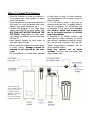
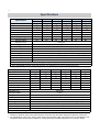
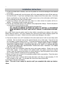
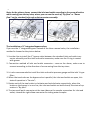
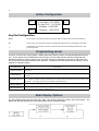
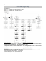
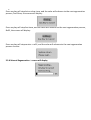
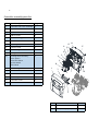
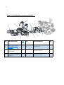
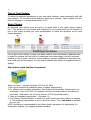
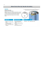
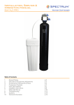
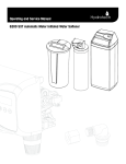
Owners Manual
89 BIF/BAF USER MANUAL
1. Read all instructions carefully before operation.
2. Avoid pinched o-rings during installation by applying (provided with install kit) NSF certified
lubricant to all seals.
3. This system is not intended for treating water that is microbiologically unsafe or of unknown
quality without adequate disinfection before or after the system.
REVISION #
0
REVISION DATE May 4,2015
54593
Canadian Head Office
655 Park St.
Regina, SK S4N 5N1
U.S. Head Office
8437 10th Avenue North
Golden Valley, MN 55427
2
Table of Contents
Unpacking / Inspection
Safety Guide
Proper Installation
Specification
Before Starting Installation
Installation Instructions
System Start Up
Programming Instructions
About The System
Maintenance
Sanitizing Procedure
Main Repair Parts
Trouble Shooting
Warranty
PAGE
2
2
3
4
4
6
8
9
10
12
15
16
23
24
Unpacking / Inspection
Be sure to check the entire softener for any shipping damage or parts loss. Also note damage to the shipping cartons. Contact the transportation company for all damage and loss
claims. The manufacturer is not responsible for damages in transit.
Small parts, needed to install the softener, are in a parts bag. To avoid loss of the small
parts, keep them in the parts bag until you are ready to use them.
Safety Guide
For your safety, the information in this manual must be followed to minimize the risk of
electric shock, property damage or personal injury.
•
•
•
•
•
Check and comply with your provincial /
coarse SOLAR salts are recommended. Do
state and local codes. You must follow
not use rock, block, granulated or ice
these guidelines.
cream making salts. They contain dirt and
Use care when handling the water softensediments, or mush and cake, and will creing system. Do not turn upside down,
ate maintenance problems.
drop, drag or set on sharp protrusions.
• Keep the salt lid in place on the softener
The water softening system works on 12
unless servicing the unit or refilling with
volt-60 Hz electrical power only. Be sure to
salt.
use only the included transformer.
• WARNING: This system is not inTransformer must be plugged into an intended for treating water that is microbiodoor 120 volt, grounded outlet only.
logically unsafe or of unknown quality
Use clean water softening salts only, at
without adequate disinfection before or
least 99.5% pure. NUGGET, PELLET or
after the system.
3
Proper Installation
This water softening system must be properly installed and located in accordance with the
Installation Instructions before it is used.
•
•
•
•
•
Do not install or store where it will not be
psi, night time pressure may exceed the
exposed to temperatures below freezing or
maximum. Use a pressure reducing valve
exposed to any type of weather. Water
to reduce the flow if necessary.
freezing in the system will break it. Do not • Softener resins may degrade in the presence of chlorine above 2 ppm. If you
attempt to treat water over 100°F.
have chlorine in excess of this amount,
Do not install in direct sunlight. Excessive
sun or heat may cause distortion or other
you may experience reduced life of the
damage to non-metallic parts.
resin. In these conditions, you may wish
to consider purchasing a whole house carProperly ground to conform with all govbon filter softener system with a chlorine
erning codes and ordinances.
reducing media.
Use only lead-free solder and flux for all
sweat-solder connections, as required by
• WARNING: Discard all unused parts and
packaging material after installation. Small
state and federal codes.
Maximum allowable inlet water pressure is
parts remaining after the installation could
125 psi. If daytime pressure is over 80
be a choke hazard.
4
Before Starting Installation
Tools, Pipe, and Fittings, Other Materials
•
•
•
•
•
•
Pliers
Screwdriver
Teflon tape
Razor knife
Two adjustable wrenches
Additional tools may be required if modification to home plumbing is required.
• Plastic inlet and outlet fittings are included
with the softener. To maintain full valve
flow, 3/4” or 1” pipes to and from the softener fittings are recommended. You
should maintain the same, or larger, pipe
size as the water supply pipe, up to the
softener inlet and outlet.
• Use copper, brass, or PEX pipe and fittings.
•
•
•
•
•
Some codes may also allow PVC plastic
pipe.
ALWAYS install the included bypass valve,
or 3 shut-off valves. Bypass valves let you
turn off water to the softener for repairs if
needed, but still have water in the house
pipes.
5/8” OD drain line is needed for the valve
drain. A 10’ length of hose is included.
with some models.
A length of 5/8” OD drain line tubing is
needed for the brine tank over flow fitting
(optional).
Nugget or pellet water softener salt is
needed to fill the cabinet or brine tank.
5
Where To Install The Softener
•
•
•
•
•
•
is least likely to occur if a leak develops.
Place the softener as close as possible to
the pressure tank (well system) or water
The manufacturer will not repair or pay for
meter (city water).
water damage.
Place the softener as close as possible to a • A 120 volt electric outlet, to plug the infloor drain, or other acceptable drain point
cluded transformer into, is needed within 6
(laundry tub, sump, standpipe, etc.).
feet of the softener. The transformer has
Connect the softener to the main water
an attached 6 foot power cable. Be sure
supply pipe BEFORE the water heater. DO
the electric outlet and transformer
NOT RUN HOT WATER THROUGH THE
are in an inside location, to protect
SOFTENER. Temperature of water passfrom wet weather.
ing through the softener must be less than • If installing in an outside location, you
100 deg. F.
must take the steps necessary to assure
Keep outside faucets on hard water to
the softener, installation plumbing, wiring,
save soft water and salt.
etc., are as well protected from the eleDo not install the softener in a place where
ments, contamination, vandalism, etc., as
it could freeze. Damage caused by
when installed indoors.
freezing is not covered by the war- • Keep the softener out of direct
ranty.
sunlight. The sun’s heat may soften and
Put the softener in a place water damage
distort plastic parts.
Note: Neutralizing
filter could be required
to correct a low pH
condition from the
HIMTLC. This can be
determined by a
proper water analysis
including Alkalynity.
Optional
Neutralizer
Filter
6
Specifications
BIF-100
BIF-150
BIF-200
BIF-300
BIF-400
BIF-500
BIFMN-100 BIFMN-150 BIFMN-200 BIFMN-300 BIFMN-400 BIFMN-500
Typical Service Flow Rate
3.0 gpm
4.0 gpm
5.0 gpm
6.0 gpm
7.0 gpm
9.0 gpm
Peak Flow Rate
6.0 gpm
10.0 gpm
12.0 gpm
14.0 gpm
16.0 gpm
18.0 gpm
Backwash Flow Rate
5.0 gpm
5.0 gpm
7.0 gpm
10.0 gpm
14.0 gpm
21.0 gpm
3
3
3
3
3
Filter Media Volume (ft3)
1.0 ft
1.5 ft
2.0ft
3.0 ft
4.0 ft
5.0 ft3
Filter Tank Size
10x44
10x54
12x52
14x65
16x65
18x65
Air Contact Tank Size
8x44
10x54
12x52
14x65
14x65
14x65
Shipping Weight
150 lbs
188 lbs
248 lbs
368 lbs
443 lbs
518 lbs
Media Loaded
Yes
Yes
No
No
No
No
Maximum Iron
30.0 ppm
Hydrogen Sulfide
5.0 ppm
Manganese
BIF Model 0.0 ppm / BIFMN Models up to 1.0 ppm
Iron Bacteria Removal
Yes
pH
BIF Models pH 7.0 - 8.5 / BIFMN Models pH 6.0 -6.9
Plumbing Connections
3/4" 90°NPT Elbows; 1" Straight NPT (89 Valve 1" Straight Only)
Electrical Requirements
Input 120V 60 Hz - Output 12V 650mA
Water Temperature
Min 39 - Max. 100° F
Water Pressure
Min. 20 - Max. 125 psi
*MN Models for low pH 6.0 - 6.9 & Manganese up to 1.0 ppm
Note: BIF/BIFMN systems using 565 Controls only available on 1.0 and 1.5 cubic foot units
Specifications
Specifications
BAF-100
BAF-150
BAF-200
BAF-300
BAF-400
BAF-500
3.0 gpm
4.0 gpm
5.0 gpm
6.0 gpm
7.0 gpm
9.0 gpm
Typical Service Flow Rate
Peak Flow Rate
6.0 gpm
10.0 gpm
12.0 gpm
14.0 gpm
16.0 gpm
18.0 gpm
Backwash Flow Rate
5.0 gpm
5.0 gpm
7.0 gpm
10.0 gpm
14.0 gpm
21.0 gpm
3
3
3
3
3
Filter Media Volume (ft3)
1.0 ft
1.5 ft
2.0ft
3.0 ft
4.0 ft
5.0 ft3
Filter Tank Size
10x44
10x54
12x52
14x65
16x65
18x65
Air Contact Tank Size
8x44
10x54
12x52
14x65
14x65
14x65
Shipping Weight
115 lbs
143 lbs
172 lbs
268 lbs
329 lbs
420 lbs
Media Loaded
Yes
Yes
No
No
No
No
Maximum Iron
30.0 ppm
Hydrogen Sulfide
Trace
Manganese
0.0 ppm
Iron Bacteria Removal
No
pH
7.0 - 8.5
Plumbing Connections
3/4" 90°NPT Elbows; 1" Straight NPT (89 Valve 1" Straight Only)
Electrical Requirements
Input 120V 60 Hz - Output 12V 650mA
Water Temperature
Min 39 - Max. 100° F
Water Pressure
Min. 20 - Max. 125 psi
Note: BAF systems using 565 Controls only available on 1.0 and 1.5 cubic foot units
•
•
Continuous operation at flow rates greater than the service flow rate may affect capacity and efficiency performance.
The manufacturer reserves the right to make product improvements which may deviate from the specifications and
descriptions stated herein, without obligation to change previously manufactured products or to note the change.
7
Installation Instructions
1. If your hot water tank is electric, turn off the power to it to avoid damage to the element
in the tank.
2. If you have a private well, turn the power off to the pump and then shut off the main water shut off valve. If you have municipal water, simply shut off the main valve. Go to the
faucet, (preferably on the lowest floor of the house) turn on the cold water until all pressure is relieved and the flow of water stops.
3. Locate the softener tank and brine tank close to a drain where the system will be installed. The surface should be clean and level.
4. Connect the inlet and outlet of the softener using appropriate fittings. Perform all plumbing according to local plumbing codes.
• Use a ½” minimum pipe or tubing size for the drain line
• ON COPPER PLUMBING SYSTEMS BE SURE TO INSTALL A GROUNDING
WIRE BETWEEN THE INLET AND OUTLET PIPING TO MAINTAIN GROUNDING.
Any solder joints near the valve must be done before connecting any piping to the valve.
Always leave at least 6" (152 mm) between the valve and joints when soldering pipes that
are connected to the valve. Failure to do this could cause damage to the valve.
5. Connect the drain hose (10 ft included) to the valve and secure it with a hose clamp (also
included). Run the drain hose to the nearest laundry tub or drain pipe. This can be ran
up overhead or down along the floor. If running the drain line more than 20 ft overhead,
it is recommended to increase the hose size to 3/4”. NEVER MAKE A DIRECT CONNECTION INTO A WASTE DRAIN. A PHYSICAL AIR GAP OF AT LEAST 1.5” SHOULD BE USED
TO AVOID BACTERIA AND WASTEWATER TRAVELLING BACK THROUGH THE DRAIN
LINE INTO THE SOFTENER.
6. Using the Allen Key (included), place the unit in the bypass position. Slowly turn on the
main water supply. At the nearest cold treated water tap nearby remove the faucet
screen, open the faucet and let water run a few minutes or until the system is free of any
air or foreign material resulting from the plumbing work.
7. Make sure there are no leaks in the plumbing system before proceeding. Close the water
tap when water runs clean.
8. Open the brine tank / cabinet salt lid and add water until there is approximately 3" (75
mm) of water in the tank. Do not add salt to the brine tank at this time.
9. Proceed to start up instructions.
Note: The unit is not ready for service until you complete the start-up instructions.
8
Installation
9
Note: As the picture shows, connect the inlet and outlet according to the arrow direction
which seeing from the top view, where you can see the mark of “Up flow” or “Down
flow” on the standard inlet and outlet connector assembly.
The installation of 1“ integrated bypass valve:
:
If you use the 1” integrated bypass instead of the three manual valve, the installation
method is showed as the picture below.
1 Use the clips to install the 1” bypass valve between the standard inlet and outlet connector assembly and the inlet and outlet connector, make sure the O-ring is coated
with grease.
2. Connection method of inlet and outlet connector:same as the above, make sure to
connect according to the direction of arrow seeing from the top view;
3. It is also recommended to install the inlet and outlet pressure gauge and the inlet Y-type
filter;
4. When the two knobs on the bypass valve is parallel, the inlet and outlet are open, this
state of operation is “Service”;
5. Rotate each of the two knobs in clockwise and anticlockwise respectively, when the
knobs on the bypass is in one line, the inlet and outlet are both closed, this state of operation is “By-pass”.
6. The two small quick connector at the two sides are the sample connection for inlet and
outlet, choose the right elbow connector for taking water samples.
10
Softener commissioning
1. This water softening system must be properly installed(check the inlet and outlet, brine
line, drain line , power supply)and located in accordance with the installation instructions before commissioning and putting into operation.
2. The control panel using four touching keys, don’t operate the keys with thick gloves.
3. Open the bypass, rinse the inlet and outlet pipe with tap water. Change the control valve
to the “Manual Regeneration” interface, initiate the control valve to the backwash process.
4. Then close the bypass valve, slowly open the inlet valve, the raw water filling the tank
and empty the air of the system, open the valve more until the backwash water is clean
5. Press any key to advance the control valve to the brine position, check and make sure the
vacuum is present at the mouth of brine, and the flow rate of brine draw meet the requirement.
6. Proceed to advance to the RINSE position, allow the water to run until it is clear. Proceed
to advance to the REFILL position, check that the brine valve is filling water into the brine
tank, allow the valve to refill to the correct amount of water. Then advance to the SERVICE position, open the outlet on the bypass.
7. Put the salt for regeneration into the brine tank.
11
Button Configuration
MENU
SET
Flow Rate: 24.5 GPM
18-Apr-2015 10:35AM
Remain: 1,280 GAL
Capacity: 1,500 GAL
+
-
Key Pad Configuration
MENU
This function is to enter the basic set up information required at the time of installation.
SET
This function is to accept the values if changed and advance to the next page in the menu.
+/-
These buttons are used to increase or decrease the value of the settings while in the programming mode.
Programming Levels
There are 3 levels to the valve program. Master options and Factory options are typically adjusted at the factory. These options link the PCB function with the type of control valve and should not be tampered with.
Advanced options are used to configure the unit when the valve is assembled to the tank so that it can function as the proper size and intended system operation. Settings are the final options chosen when the unit is
installed to a specific location.
PROGRAM LEVEL
USER ACCESS
USER SETTINGS(I)
These settings are programmed when the unit is installed. The settings should only be adjusted by a qualified person.
MAIN MENU (II)
These settings are programmed when the unit is installed. The settings should only be adjusted by a qualified person.
These settings are programmed by the factory and should be adjusted when the valve is assembled into a
ADVANCED MENU (II) unit or system. It contains important settings so the valve will operate properly for the type of system it is
intended for. The settings should only be changed by qualified person.
This menu contains key diagnostics for trouble shooting the system.
HISTORY MENU (IV)
FACTORY MENU (V)
These settings are programmed by the factory. The settings are important for the operation of the valve
that should only be changed by a qualified person.
Main Display Options
The main display page shows the Flow Rate, Date, Time Of Day, Remaining Volume, and Total Volume. The
display will alternate between the main page and the dealer information page.
12
User Settings (Level I)
Press MENU key.
Press + or - to change menu option. Press SET to enter.
Press + or - to change value. Press SET to accept.
CAUTION:
The values in this page are for illustration purpose and can be changed
by the factory without notice.
Please contact Customer Service to
confirm proper settings.
Filter Mode
Press SETTINGS.
Press UP or DOWN to change value.
Press SELECT to accept change and advance to next page.
DATE AND TIME
Time of day is for normal operation of system and the
scheduling of the regeneration time. The date is used
in a diagnostic function to track the last time the system regenerated.
MANUAL REGENERATION
To start an immediate regeneration select the Manual
Regen option.
This setting determines the time of day to perform a
scheduled regeneration.
HARDNESS
DEALER INFORMATION
This value is the maximum compensated water hard- This is optional. Dealer information can be added.
ness in grains per gallon of the raw water supply. It is
used to calculate the system capacity. If Ferrous Iron
is present add 4 gpg for every 1 ppm of Ferrous Iron.
13
Manual Regeneration
Press “■” key to initiate a manual regeneration, the regeneration steps will be different
according to different valve type:
• The regeneration steps of DOWN FLOW valve:backwash、brine +slow rinse、fast
rinse、service +refill;
• The regeneration steps of UP FLOW valve:brine +slow rinse、backwash、fast rinse、
service +refill;
Set the Down Flow valve as an example, when the valve get into backwash,
the screen will display:
Press any key will stop backwash, and the valve will advance to the next regeneration process, Brine, the screen will display:
14
Press any key will stop brine +slow rinse, and the valve will advance to the next regeneration
process, Fast Rinse, the screen will display:
Press any key will stop fast rinse, and the valve will advance to the next regeneration process,
Refill, the screen will display:
Press any key will stop service + refill, and the valve will advance to the next regeneration
process: service
2.3.6 Manual Regeneration:screen will display
15
Controller assembly parts list:
No.
Part description
Qty
1
Controller front cover assembly
1
2
89 PCB
1
3
PCB absorb shock foam
1
4
PCB fix screws
4
5
85HE mounting plate
1
6
Screws
8
7
85 drive gear
1
8
Connect screw
1
9
85HE main gear
1
10
Brine gear screw
1
11
Locating wheel assembly:
1
14
13
11 12
17
10
8
9
three options
6
Down flow wheel
Up flow wheel
15
18
Filter wheel
12
85HE brine gear
1
13
Micro switch screws
2
14
Micro switch
2
15
Valve body connect screws
2
16
Controller screws
4
17
Controller back cover assembly
1
1
3
7
16
5
4
2
18
Motor 12VAC 3W
1
19
Wire(not displayed)
Some
16
Parts list of Standard connection assembly :
6
3
10
9
7
8
No.
1
2
3
2
Part description
Big O-ring of Adaptor
coupling
Adaptor coupling of 89
control valve
Small O-ring of adaptor
coupling
5
4
1
Qty
No.
Part description
Qty
2
6
89 secure clip
2
2
7
89 valve connector
1
2
8
Connector O-ring
2
17
Parts list of control valve body:
No.
Part description
Qty
1
89 valve body
1
2
95 secure clip
1
3
DLFC assembly:optional
1
12
14
13
1S、2S、3S、4S、
11
1#、3#、4#、5#、6#
4
Drain elbow O-ring
1
5
Drain elbow: 1/2”、
1
10
9
3/4”
6
Brine valve injector stem
8
1
assembly
7
7
Spacer and seal assembly
1
8
Three options of piston
1
Down flow piston
6
5
4
3
1
15
Up flow piston
Filter piston
16 17
18
2
19
20
21
26
22
23
27
24
25
18
8
Three options of piston
1
Down flow piston
Up flow piston
Filter piston
9
Piston retainer
1
10
End plug
1
11
Piston pin
1
12
Piston rod
1
13
End plug retainer
1
14
End plug retainer screws
3
15
Brine line adaptor assem-
1
bly:optional BLFC:
0.7gpm
BLFC:0.95gpm
16
Injector assembly:
1
optional
grey、purple、red、
white、blue、yellow
17
Injector cover O-ring
1
18
Injector cover
1
19
Injector cover screws
2
20
Tank mouth O-ring
1
21
Adapter O-ring
1
22
Center pipe adapter
1
23
Center pipe O-ring
1
24
Valve bottom connector
1
25
Bottom connector screws
2
26
Brass nuts
1
27
Brine line elbow assembly
1
19
Care of Your System
To retain the attractive appearance of your new water softener, clean occasionally with mild
soap solution. Do not use abrasive cleaners, ammonia or solvents. Never subject your softener to freezing or to temperatures above 100°F.
Resin Cleaner
An approved resin cleaner must be used on a regular basis if your water supply contains
iron. The amount of resin cleaner and frequency of use is determined by the quantity of
iron in your water (consult your local representative or follow the directions on the resin
cleaner package).
Sanitizing Procedure
Care is taken at the factory to keep your water softener clean and sanitary. Materials used
to make the softener will not infect or contaminate your water supply, and will not cause
bacteria to form or grow. However, during shipping, storage, installing and operating, bacteria could get into the softener. For this reason, sanitizing as follows is suggested when installing.
Sani-System Liquid Sanitizer Concentrate
Item# 80030021—Softener Sanitizer 0.25 fl.oz (24 Pack)
1. Be sure to complete all installation steps, including programming.
2. For effective and complete sanitization, Sani-System Liquid Sanitizer Concentrate is recommended. Pour one 0.25 fl. Oz. package into the brine well located in the cabinet or
brine tank. (Alternative use 3/4 oz of common 5.25% household bleach)
3. Start an immediate regeneration. (See page 11)
4. The Softener Sanitizer Solution is drawn into and through the water softener to sanitize
it. This sanitizing regeneration is over in about two hours. Then, soft water is available
for your use.
NOTE: Sanitizing is recommended by the Water Quality Association for disinfecting. On
some water supplies, they suggest periodic sanitizing.
20
Brine Tank & Res-Up Feeder Assembly
80030022
64 OZ PRO RESCARE
21
Warranty
Canature Watergroup guarantees that your new water conditioner is built of quality material and workmanship. When properly installed and maintained, it will give years of trouble free service.
Five Year Limited Warranty
Canature WaterGroup will replace the salt tank or cabinet tank, the fibreglass mineral tank,
the ion exchange resin, and valve parts provided the failure is due to a defect in material or
workmanship and not the result of damage from any of the conditions described in the general conditions of this warranty.
General Conditions
Damage to any part of this water conditioner as a result of misuse, misapplication, neglect,
alteration, accident, installation or operation contrary to our printed instructions, damage to
ion exchange resin and seals caused by chlorine / chloramines in the water supply, or damage caused by any force of nature is not covered in this warranty. We will repair or replace
defective parts if our warranty department determines it to be defective under the terms of
this warranty. Canature WaterGroup assumes no responsibility for consequential damage,
labour or expense incurred as a result of a defect or failure.