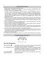
1
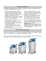
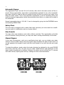
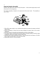
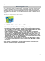
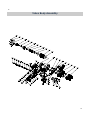
Customer Care Line 1-888-317-6364 Tested and Certified by the Water Quality Association to CSA B483.1. Proud member of Canadian Institute of Plumbing & Heating. Proud member of Canadian Water Quality Association. 1. Read all instructions carefully before operation. 2. Avoid pinched o-rings during installation by applying (provided with install kit) NSF certified lubricant to all seals. 3. This system is not intended for treating water that is microbiologically unsafe or of unknown quality without adequate disinfection before or after the system. REVISION # 5 REVISION DATE December 12, 2012 Canadian Head Office 655 Park St. Regina, SK S4N 5N1 Eastern Sales & Distribution 20 Steckle Place, Unit 21 Kitchener ON N2E 2C3 Installation and Operation Manual EcoSmart Series High Efficiency Water Softeners 2 Table of Contents PAGE 2 Safety Guide Proper Installation Unpacking / Inspection Specification Before Starting Installation General Installation Installation Instructions Start Up Instructions Programming About The Water Softener System Specifications Maintenance Sanitize Procedure Valve Powerhead Assembly Valve Body Assembly Trouble Shooting Warranty 3 3 4 5 6 7 8 8 10 11 13 15 16 18 23 24 Safety Guide For your safety, the information in this manual must be followed to minimize the risk of electric shock, property damage or personal injury. Check and comply with your provincial / coarse SOLAR salts are recommended. Do state and local codes. You must follow not use rock, block, granulated or ice these guidelines. cream making salts. They contain dirt and Use care when handling the water softensediments, or mush and cake, and will creing system. Do not turn upside down, ate maintenance problems. drop, drag or set on sharp protrusions. Keep the salt lid in place on the softener The water softening system works on 12 unless servicing the unit or refilling with volt-60 Hz electrical power only. Be sure to salt. use only the included transformer. WARNING: This system is not inTransformer must be plugged into an intended for treating water that is microbiodoor 120 volt, grounded outlet only. logically unsafe or of unknown quality Use clean water softening salts only, at without adequate disinfection before or least 99.5% pure. NUGGET, PELLET or after the system. 2 3 Proper Installation This water softening system must be properly installed and located in accordance with the Installation Instructions before it is used. Install or store where it will not be ex- 125 psi. If daytime pressure is over 80 posed to temperatures below freezing or psi, night time pressure may exceed the exposed to any type of weather. Water maximum. Use a pressure reducing valve freezing in the system will break it. Do not to reduce the flow if necessary. attempt to treat water over 100°F. Softener resins may degrade in the presDo not install in direct sunlight. Excessive ence of chlorine above 2 ppm. If you sun or heat may cause distortion or other have chlorine in excess of this amount, damage to non-metallic parts. you may experience reduced life of the Properly ground to conform with all govresin. In these conditions, you may wish erning codes and ordinances. to consider purchasing a whole house carUse only lead-free solder and flux for all bon filter (or ECS-34) softener system with sweat-solder connections, as required by a chlorine reducing media. state and federal codes. WARNING: Discard all unused parts and The water softening system requires a packaging material after installation. Small minimum water flow of three gallons per parts remaining after the installation could minute at the inlet. be a choke hazard. Maximum allowable inlet water pressure is Unpacking / Inspection Be sure to check the entire softener for any shipping damage or parts loss. Also note damage to the shipping cartons. Contact the transportation company for all damage and loss claims. The manufacturer is not responsible for damages in transit. Small parts, needed to install the softener, are in a parts bag. To avoid loss of the small parts, keep them in the parts bag until you are ready to use them. 43” 35” 26” 13” 18” 13” 18” 13” 18” 3 4 Specifications Specifications Maximum Hardness Removal Factory Settings - High Efficiency Salt Used Water Used System Capacity High Capacity Settings Salt Used Regeneration Water Used System Capacity High Capacity Resin Coconut Activated Carbon Integrated Meter in Bypass Plumbing Connections Flow Rate @ 15 psi Pressure Drop Salt Storage Capacity Shipping Weight Maximum Efficiency Electrical Requirements Maximum Water Temperature Water Pressure Foot Print ECS-20 ECS-24 ECS-34 ECS-39 19,500 grains 24,180 grains 34,320 grains 39,000 grains 1.5 lbs 9.6 gal 7,300 grains 2.1 lbs 11.7 gal 11,800 grains 2.4 lbs 15.8 gal 13,400 grains 3.0 lbs 17.9 gal 15,400 grains 3.7 lbs 5.3 lbs 21.4 gal 32.5 gal 18,000 grains 20,500 grains 0.7 cubic feet 0.8 cubic feet No Yes Yes Yes 3/4" or 1" 3/4" or 1" 10.2 gpm 10.0 gpm 120 lbs 170 lbs 68.3 lb 84.3 lb 5,600 grains /lb salt 120V 50/60 Hz 120 degrees Fahrenheit min. 20 - max. 120 psi 13 inches wide x 18 inches long 6.0 lbs 34.6 gal 25,700 grains 1.0 cubic feet No Yes 3/4" or 1" 10.0 gpm 170 lbs 87.5 lb 3.0 lbs 16.9 gal 12,000 grains 0.5 cubic feet No Yes 3/4" or 1" 10.9 gpm 80 lbs 58.5 lb Continuous operation at flow rates greater than the service flow rate may affect capacity and efficiency performance. The manufacturer reserves the right to make product improvements which may deviate from the specifications and descriptions stated herein, without obligation to change previously manufactured products or to note the change. Water Quality If the water supply contains sand, sulfur, bacteria, iron bacteria, tannins, algae, oil, acid, or other unusual substances, pre-treatment must be added to remove these contaminants before the EcoSmart Series Softener Systems. Iron In Your Water Supply (Problem Water) Ferrous Iron (sometimes called clear water or dissolved iron) can be removed with a wa- ter softener. The EcoSmart softener should be cleaned with a resin bed cleaner at least every 6 months. Follow instructions carefully. You should also increase your water hardness setting by 4 grains per gallon for every 1 ppm of ferrous iron. THE MAXIMUM LIMIT FOR FERROUS IRON IS 10 PPM. Ferric Iron, Organic Iron, Bacterial Iron, or Colloidal Iron cannot be removed by a softener system and must be removed prior to the EcoSmart Series Softener Systems. 4 5 Before Starting Installation Tools, Pipe, and Fittings, Other Materials Pliers Screwdriver Teflon tape Razor knife Two adjustable wrenches Additional tools may be required if modification to home plumbing is required. Plastic inlet and outlet fittings are included with the softener. To maintain full valve flow, 3/4” or 1” pipes to and from the softener fittings are recommended. You should maintain the same, or larger, pipe size as the water supply pipe, up to the softener inlet and outlet. Use copper, brass, or PEX pipe and fittings. Some codes may also allow PVC plastic pipe. ALWAYS install the included bypass valve, or 3 shut-off valves. Bypass valves let you turn off water to the softener for repairs if needed, but still have water in the house pipes. 1/2” Drain line is needed for the valve drain. A 10’ length of hose is included. with some models. A length of 1/2” drain line tubing is needed for the brine tank over flow fitting (optional). Nugget or pellet water softener salt is needed to fill the cabinet tank. Where To Install The Softener Place the softener as close as possible to is least likely to occur if a leak develops. the pressure tank (well system) or water The manufacturer will not repair or pay for meter (city water). water damage. Place the softener as close as possible to a A 120 volt electric outlet, to plug the infloor drain, or other acceptable drain point cluded transformer into, is needed within 6 (laundry tub, sump, standpipe, etc.). feet of the softener. The transformer has Connect the softener to the main water an attached 6 foot power cable. Be sure supply pipe BEFORE the water heater. DO the electric outlet and transformer NOT RUN HOT WATER THROUGH THE are in an inside location, to protect SOFTENER. Temperature of water passfrom wet weather. ing through the softener must be less than If installing in an outside location, you 110 deg. F. must take the steps necessary to assure Keep outside faucets on hard water to the softener, installation plumbing, wiring, save soft water and salt. etc., are as well protected from the eleDo not install the softener in a place where ments, contamination, vandalism, etc., as it could freeze. Damage caused by when installed indoors. freezing is not covered by the war- Keep the softener out of direct ranty. sunlight. The sun’s heat may soften and Put the softener in a place water damage distort plastic parts. 5 6 General Installation Typical Softener Location You must first decide how to run in and out pipes to the softener. Look at the house main water pipe at the point where you will connect the softener. Is the pipe soldered copper, glued plastic, PEX, or threaded brass/galvanized? What is the pipe size? Now look at the typical installation illustrations below. Use it as a guide when planning your particular installation. Make sure you have correctly identified the inlet of the system. Be sure to direct raw, hard water to the softener valve inlet fitting. The bypass valve is marked IN and OUT arrows. Installation Instructions 1. If your hot water tank is electric, turn off the power to it to avoid damage to the element in the tank. 2. If you have a private well, turn the power off to the pump and then shut off the main water shut off valve. If you have municipal water, simply shut off the main valve. Go to the faucet, (preferably on the lowest floor of the house) turn on the cold water until all pressure is relieved and the flow of water stops. 3. Locate the softener tank and brine tank close to a drain where the system will be installed. The surface should be clean and level. 4. Connect the inlet and outlet of the softener using appropriate fittings. Perform all plumbing according to local plumbing codes. Use a ½” minimum pipe or tubing size for the drain line ON COPPER PLUMBING SYSTEMS BE SURE TO INSTALL A GROUNDING WIRE BETWEEN THE INLET AND OUTLET PIPING TO MAINTAIN GROUNDING. Any solder joints near the valve must be done before connecting any piping to the valve. Always leave at least 6" (152 mm) between the valve and joints when soldering pipes that are connected to the valve. Failure to do this could cause damage to the valve. 6 7 Installation Instructions (Continued) 5. Connect the drain hose (10 ft included) to the valve and secure it with a hose clamp (also included). Run the drain hose to the nearest laundry tub or drain pipe. This can be ran up overhead or down along the floor. If running the drain line more than 20 ft overhead, it is recommended to increase the hose size to 3/4”. NEVER MAKE A DIRECT CONNECTION INTO A WASTE DRAIN. A PHYSICAL AIR GAP OF AT LEAST 1.5” SHOULD BE USED TO AVOID BACTERIA AND WASTEWATER TRAVELLING BACK THROUGH THE DRAIN LINE INTO THE SOFTENER. 6. Using the Allen Key (included), place the unit in the bypass position. Slowly turn on the main water supply. At the nearest cold treated water tap nearby remove the faucet screen, open the faucet and let water run a few minutes or until the system is free of any air or foreign material resulting from the plumbing work. 7. Make sure there are no leaks in the plumbing system before proceeding. Close the water tap when water runs clean. 8. Open the cabinet salt lid and add water until there is approximately 3" (75 mm) of water (5 gallons) in the cabinet tank. Do not add salt to the brine tank at this time. 9. Proceed to start up instructions. Note: The unit is not ready for service until you complete the start-up instructions. 7 8 Start-Up Instructions 1. Plug the valve into an approved power source. 2. When power is supplied to the control, the screen will display “INITIALIZING WAIT PLEASE” while it finds the service position. 3. If screen is locked, press MENU for 3 seconds to unlock. Press SET/REGEN and hold for 3 seconds to initiate a manual regeneration. An option for delayed or immediate regeneration will appear. Press the SET / REGEN button again and “Delayed” will begin flashing, press the down arrow button to have “Immediate” flash. Press the SET / REGEN button and then press the MENU button and the valve will immediately start moving to the BACKWASH position. 4. Open the inlet on the bypass valve slowly and allow water to enter the unit. Allow all air to escape from the unit before turning the water on fully then allow water to run to drain for 3-4 minutes or until all media fines are washed out of the softener indicated by clear water in the drain hose. 5. Press any button to advance to the BRINE position. Check the water level in the brine tank to insure the valve is drawing brine properly. 6. Press any button to advance to the RINSE position. Check the drain line flow. Allow the water to run for 3-4 minutes or until the water is clear. 7. Press any button to advance to the REFILL position. Check that the valve is filling water into the brine tank. Allow the valve to refill for the full amount of time as displayed on the screen to insure a proper brine solution for the next regeneration. 8. The valve will automatically advance to the SERVICE position. Open the outlet valve on the bypass, then open the nearest treated water faucet and allow the water to run until clear, close the tap and replace the faucet screen. 9. Add salt into the cabinet tank. 10. Program time, date, hardness and people into controller using Programming Instructions Programming Instructions Key Pad Configuration MENU BUTTON “ ”: The function of this key is to enter the level one programming mode where the valve settings can be adjusted. SET / REGEN BUTTON “•”: This button has two functions. The first is to initiate a manual regeneration by holding the button for 3 or more seconds. The second function is while in programming mode, pressing this key allows the user to change the value of each setting. UP / DOWN “ ”: settings while in the These buttons are used to increase or decrease the value of the programming mode. 8 9 System Initialization When power is first supplied, the valve may take up to two minutes to initialize the valve. During this time the valve will show “INTIALIZING WAIT PLEASE”. Do not touch any buttons at this time. One beep signals the valve has reached the service position. it will display the current date and time. Manual Regeneration (Immediate or Delayed) If screen is locked, press MENU for 3 seconds to unlock. To initiate an Immediate Regeneration, press the SET / REGEN button for 3 seconds, an option for Delayed or Immediate Regeneration will appear. Press the SET / REGEN button again and delayed will begin flashing, press the down arrow button to have Immediate flash, press the SET / REGEN button and then press the MENU button and the valve will immediately start into manual regeneration. To initiate a Delayed Regeneration, press the SET / REGEN button for 3 seconds, then press the menu button and a regeneration will be queued to the next pre-set regeneration time (2:00 a.m.). Setting Current Time 1. If screen is locked, press MENU for 3 seconds to unlock. Press MENU again to enter level one programming mode and adjust CURRENT TIME. 2. Press SET/REGEN to adjust hours. When you have entered the change value mode, the curser will blink. Press UP OR DOWN arrows to change the hour values. Press SET/ REGEN again to accept the hour value and advance to change the minutes value. Press UP OR DOWN arrows to change the minute values. Press SET/REGEN again to accept the minute values and advance to adjust the AM/PM values. Press UP OR DOWN to change the AM/PM value. Press SET/REGEN again to accept the AM/PM value and exit. When you have exited the change value mode, the curser will stop flashing. Setting Current Date 1. Press DOWN to advance to CURRENT DATE. 2. Using the same procedure as setting the time, press SET/REGEN to enter value change mode. Setting Number of People in Household 1. Press DOWN to advance to NUMBER PEOPLE. 2. Press the SET/REGEN to change the value. Press UP OR DOWN to change the values. Setting Water Hardness 1. Press DOWN to advance to WATER HARDNESS. 2. Press the SET/REGEN to change the value. Press UP OR DOWN to change the values. 9 10 Setting Vacation Mode 1. Press DOWN to advance to VACATION MODE. 2. Press the SET/REGEN to change the value. Press UP OR DOWN to change the values. Vacation mode is only used when home is left un-occupied for lengthy amounts of time and the owner wishes to have a periodic flush of the softener system. The unit will not operate properly if vacation mode is left on. Exiting Programming Mode At any time, press the “ MENU” to accept all changes and return to main page display. Level I User Program Mode 1 PARAMETER CURRENT TIME 2 CURRENT DATE 3 NUMBER PEOPLE 4 WATER HARDNESS 5 VACATION MODE OPTIONS DESCRIPTION This option is the current time of day. This option is the current date. The date is used to track the last time the system regenerated. This value is the number of people living in the home. It is used to calculate the amount of water needed for daily use and the reserve capacity of the system. Yes This value is the maximum water hardness in grains per gallon of the raw water supply. It is used to calculate the system capacity. This function may be activated by the user during a prolonged absence such as vacation. The system will perform a brief backwash and rinse based on the advanced setting. The purpose is to keep the water fresh in the softener tank and plumbing system. No About The Water Softener System Control Operation During A Power Failure In the event of a power failure, the valve will keep track of the time and day for 48 hours. The programmed settings are stored in a non-volatile memory and will not be lost during a power failure. If power fails while the unit is in regeneration, the valve will finish regeneration from the point it is at once power is restored. If the valve misses a scheduled regeneration due to a power failure, it will queue a regeneration at the next regeneration time once power is restored. Main Display This valve is controlled with simple, user-friendly electronics displayed on a large LCD screen. The main page displays the current date and time. In addition, the main page also shows key valve information and statistics including; current capacity setting, volume remaining, date of last regeneration, current flow rate, and peak flow rate. MAY 8, 2009 9:05 AM CAPACITY 1,350 GAL VOLUME REMAINING 1,125 GAL REGEN DAYS 7 DAYS REMAINING DAYS 5 DAYS REGENERATION TIME 2:00 AM LAST REGEN MAY 4, 2009 CURRENT FLOW 1.5 GPM PEAK FLOW 5.8 GPM 10 11 Automatic Hard Water Bypass During Regeneration For emergency needs, hard water is available to the home during the regeneration cycles. However, you should avoid using HOT water because the water heater will refill with the hard water. System Configuration Valve Set-up VALVE SETTINGS (MINUTES) MODEL MUNICIPAL WATER (HIGH EFFICIENCY) MUNICIPAL WATER (HIGH CAPACITY) PROBLEM WATER (HIGH CAPACITY) BACKWASH BRINE / RINSE RINSE BACKWASH BRINE / RINSE RINSE BACKWASH BRINE / RINSE RINSE ECS-20 1 21 1 1 35 1 4 35 4 ECS-24 1 23 1 1 52 1 5 52 5 ECS-34 2 33 1 2 80 1 10 80 10 Change Valve Cycle Settings 1. If screen is locked, press MENU for 3 seconds to unlock. 2. Press and hold UP AND DOWN for three seconds to enter Level Two Master Programming. 3. Press the DOWN and advance to the BACKWASH menu option. Press SET/REGEN to edit the BACKWASH minutes. Press UP OR DOWN arrows to change the BACKWASH minute values. Press SET/REGEN again to accept the new value. 4. Press the DOWN twice to advance to the RINSE menu option. Press SET/REGEN to edit the RINSE minutes. Press UP OR DOWN arrows to change the RINSE minute values. Press SET/REGEN again to accept the new value. 5. Press MENU to exit programming mode. Change Efficiency Settings MODEL ECS-20 ECS-24 ECS-34 ECS-39 HIGH EFFICIENCY SALT UNIT SETTING CAPACITY 1.5 7,300 2.1 11,800 2.4 13,400 3.0 15,400 HIGH CAPACITY SALT UNIT SETTING CAPACITY 3.0 12,000 3.7 18,000 5.3 20,500 6.0 25,700 PROBLEM WATER SALT UNIT SETTING CAPACITY 5.0 14,000 7.0 19,600 8.0 22,400 10.0 30,000 1. If screen is locked, press MENU for 3 seconds to unlock. 2. Press and hold UP AND DOWN for three seconds to enter Level Two Master Programming. 3. Press the DOWN and advance to the SALT SETTING menu option. Press SET/REGEN to edit the SALT SETTING. Press UP OR DOWN arrows to change the SALT SETTING values. Press SET/REGEN again to accept the new value. 4. Press the DOWN and advance to the UNIT CAPACITY menu option. Press SET/REGEN to edit the UNIT CAPACITY. Press UP OR DOWN arrows to change the UNIT CAPACITY values. Press SET/REGEN again to accept the new value. 5. Press MENU to exit programming mode. 11 12 Automatic Bypass The regeneration cycle can last 30 to 80 minutes, after which soft water service will be restored. During regeneration, hard water is automatically bypassed for use in the household. Hot water should be used as little as possible during this time to prevent hard water from filling the water heater. This is why automatic regeneration is set for sometime during the night and manual regenerations should be performed when little or no water will be used in the household. Normal regeneration time is 2:00 AM. It can be changed by going into the PROGRAM menu and selecting REGEN TIME. Safety Float The brine tank is equipped with a safety float which prevents your brine tank from overfilling as a result of a malfunction such as a power failure. New Sounds You may notice new sounds as your water softener operates. The regeneration cycle lasts up to 80 minutes. During this time, you may hear water running intermittently to the drain. Manual Bypass In the case of emergency, such as an overflowing brine tank, you can isolate your water softener from the water supply using the bypass valve located at the back of the control. In normal operation the bypass is open with the on/off knobs in line with the inlet and outlet pipes. To isolate the softener, simply rotate the knobs clockwise (as indicated by the word BYPASS and arrow) until they lock. You can use your water related fixtures and appliances as the water supply is bypassing the softener. However, the water you use will be hard. To resume soft water service, open bypass valve by rotating the knobs counterclockwise. 12 13 Maintenance Adding Salt Use only crystal water softener salt. Check the salt level monthly. It is important to maintain the salt level above the water level. To add salt, simply lift the salt lid and add the salt directly into the brine tank. Be sure the brine well cover is on and fill only to the height of the brine well. Bridging Humidity or wrong type of salt may create a cavity between the water and the salt. This action, known as “bridging”, prevents the brine solution from being made, leading to your water supply being hard. If you suspect salt bridging, carefully pound on the outside of the brine tank or pour some warm water over the salt to break up the bridge. This should always be followed up by allowing the unit to use up any remaining salt and then thoroughly cleaning out the brine tank. Allow four hours to produce a brine solution, then manually regenerate the softener. Care of Your System To retain the attractive appearance of your new water softener, clean occasionally with mild soap solution. Do not use abrasive cleaners, ammonia or solvents. Never subject your softener to freezing or to temperatures above 120°F. Resin Cleaner An approved resin cleaner must be used on a regular basis if your water supply contains iron. The amount of resin cleaner and frequency of use is determined by the quantity of iron in your water (consult your local representative or follow the directions on the resin cleaner package). 13 14 Cleaning Injector Assembly Sediment, salt and silt will restrict or clog the injector. A clean water supply and pure salt will prevent this from happening. The injector assembly is located on the right side of the control valve. This assembly is easy to clean. 1. Shut off the water supply to your softener and reduce the pressure by opening a cold soft water faucet. 2. Using a screwdriver, remove the two screws holding the injector cover to the control valve body. 3. Carefully remove the assembly and disassemble as shown in above figure. 4. The injector orifice is removed from the valve body by carefully turning it out with a large screwdriver. Remove the injector throat the same way. 5. Carefully flush all parts including the screen. Use a mild acid such as vinegar or Pro-Rust Out to clean the small holes in the orifice and throat. 6. Reassemble using the reverse procedure. 14 15 Sanitizing Procedure Care is taken at the factory to keep your water softener clean and sanitary. Materials used to make the softener will not infect or contaminate your water supply, and will not cause bacteria to form or grow. However, during shipping, storage, installing and operating, bacteria could get into the softener. For this reason, sanitizing as follows is suggested when installing. Sani-System Liquid Sanitizer Concentrate Item# 80030021—Softener Sanitizer 0.25 fl.oz (24 Pack) 1. Be sure to complete all installation steps, including programming. 2. For effective and complete sanitization, EcoSmart recommends Sani-System Liquid Sanitizer Concentrate. Pour one 0.25 fl. Oz. package into the brine well located in the cabinet tank. (Alternative use 3/4 oz of common 5.25% household bleach) 3. Start an immediate regeneration. If screen is locked, press MENU for 3 seconds to unlock. To initiate an Immediate Regeneration, press the SET / REGEN button for 3 seconds, an option for Delayed or Immediate Regeneration will appear. Press the SET / REGEN button again and delayed will begin flashing, press the down arrow button to have Immediate flash, press the SET / REGEN button and then press the MENU button and the valve will immediately start into manual regeneration. 4. The Softener Sanitizer Solution is drawn into and through the water softener to sanitize it. This sanitizing regeneration is over in about two hours. Then, soft water is available for your use. NOTE: Sanitizing is recommended by the Water Quality Association for disinfecting. On some water supplies, they suggest periodic sanitizing. 15 16 Valve Powerhead Assembly To order replacement parts contact your dealer. For help in locating your dealer please call 1-877-655-6686. 16 17 Powerhead Assembly Parts List Item No. Part No. Part Description Quantity B01 A26 B02 B03 05010037 13000426 05056084 05056510 05030014 Screw-ST2.9×10 Screw-ST2.9×13(Large Wafer) Screw-ST3.5x13 Motor-12v/2rpm Motor Power Cable 8 1 8 1 1 11700005 05056098 05030006 05030009 05030007 05030005 05030016 05056089 05030008 05010023 05056016 05056141 13111004 05056166 05056083 05030002 05056139 05030010 05010031 Wire Connector Motor Pin Bnt85 Mounting Plate Bnt85 Drive Gear Bnt85 Main Gear Bnt85 Housing Bnt185 Housing Nut-M4 Bnt85 Brine Gear Magnet-φ3×2.7 Refill Regulator Washer-4x12 Washer-4x9 Screw-ST4.2×12(Large Wafer) Screw-M4x14 Bnt85 Piston Rod Washer-3x13 Bnt85 Main Pcb Meter Assembly 2 1 1 1 1 1 1 1 1 1 1 1 1 1 1 1 1 1 1 05010046 Meter Strain Relief 1 05010029 Power Cable 1 05010035 Power Strain Relief 1 19010105 Wire Rope-3×100 2 05030011 05030021 05030003 05030012 05030015 05030017 Bnt85 Display Bnt85 Wiring Harness Bnt85 Cover Bnt85 Label Bnt185 Cover Bnt185 Label 1 1 1 1 1 1 B04 B05 B06 B07 B08 B08* B09 B10 B11 B12 B13 B14 B15 B16 A04 B17 B18 B19 B20 B20* 17 18 Valve Body Assembly 18 19 Valve Body Assembly Parts List Item No. Part No. Part Description Quantity A01 05056087 Screw-M5×12(Hexagon) 3 A02 05056088 Screw-M5×16(Hexagon with Washer) 2 A03 05056047 End Plug Retainer 1 A04 05030002 Bnt85 Piston Rod 1 A05 05056097 Piston Pin 1 A06 05056023 End Plug 1 A07 05056070 Quad Ring 2 A08 05056024 End Plug Washer 1 A09 05056022 Piston Retainer 1 A10 05056181 Piston (Electrical) 1 A11 05056104 Muffler 1 A12 05056021 Spacer 4 A13 05056073 Seal 5 A14 05030001 Bnt85 Valve Body 1 A15 05056129 O-ring-φ23×3 4 A16 05056025 Adaptor Coupling 2 A17 05056044 Adaptor Clip 2 A18 05056090 Screw-ST4.2×13(Hexagon with Washer) 2 A19 21709003 Secure Clip 2 A20 05056140 Valve Connector 1 A21 05056065 O-ring-φ23.6×2.65 2 A22 21319006 Screw Adaptor 2 A23 05056508 Screw-M5×12(Hexagon with Washer) 5 A24 05030004 Bnt85 End Cover 1 A25 05030013 O-ring-φ30×2.65 1 A26 13000426 Screw-ST2.9×13(Large Wafer) 2 A27 07060007 Valve Bottom Connector 1 A28 26010103 O-ring-φ25×3.55 1 A29 05056063 O-ring-φ78.74×5.33 1 A30 05056086 Screw-M5×30(Hexagon with Washer) 2 A31 05056029 Injector Cover 1 A32 05056072 O-Ring-φ24×2 1 A33 05056027 Injector Nozzle 1 A34 05056103 Injector Screen 1 A35 05056028 Injector Throat 1 A36 05056035 BLFC Button Retainer 1 A37 05056191 BLFC-2# 1 A38 05056138 O-Ring-φ14×1.8 1 A39 05056100B BLFC Fitting 1 A40 05056106 Brine Line Screen 1 A41 05056107 BLFC Tube Insert 1 19 20 Valve Body Assembly Parts List (Continued) A42 05056033 BLFC Ferrule 1 A43 05056108 BLFC Fitting Nut 1 A44 05056177 Injector Body 1 A45 05056075 Injector Seat 1 A46 05056134 O-Ring-φ12×2 2 A47 05056054 Injector Stem 1 A48 05056031 Injector Spacer 1 A49 05056081 O-Ring-φ12.5×1.8 1 A50 05056030 Injector Cap 1 A51 05056093 Injector Screen 1 A52 05010049 Special Washer 1 A53 05056105 Retaining Ring 1 A54 05056172 1 A55 05010082 Secure Clip-S Drain Fitting-B A56 05056186 DLFC-2# 1 A57 05056066 O-Ring-φ11×2 1 A58 05056067 O-Ring-φ7.8×1.9) 2 A59 05056037 Air Disperser 1 A60 05056165 Injector Body (Filter) 1 1 20 21 Bypass Assembly 21 22 Bypass Parts List Item No. Part No. Part Description Quantity C01 C02 C03 C04 A19 A22 A21 C05 A46 C06 C07 C08 05056147 26010028 05056148 05056149 21709003 21319006 05056065 05056172 05056134 05056146 05056145 05056150 Bypass Knob O-Ring-φ28×2.65 Bypass Plug Bypass Seal Secure Clip Screw Adaptor O-Ring-φ23.6×2.65 2 4 2 2 2 2 2 2 1 2 1 2 C09 C10 C11 C12 C13 C14 C15 A15 A16 A17 A18 05010079 05010014 05010078 05010077 05010083 05010019 26010046 05056129 05056025 05056044 05056090 Secure Clip-S O-Ring-φ12×2 Bulkhead Bypass Body Collar-φ32×2.5 Impeller Pin Impeller Magnet-φ4×3 Impeller Holder Adaptor Distributor Pin Holder O-ring-φ27×3 O-ring-φ23×3 Adaptor Coupling Adaptor Clip Screw-ST4.2×13(Hexagon with Washer) 1 1 2 1 1 2 1 3 1 2 2 22 23 Trouble Shooting Issue A. Unit fails to initiate a regeneration cycle. Possible Cause 1. No power supply. 2. Defective circuit board. 3. Power failure. 4. Defective meter. 1. By-pass valve open. 2. Out of salt or salt level below water level. 3. Plugged injector / screen. 4. Flow of water blocked to brine tank. 5. Hard water in hot water tank. 6. Leak between valve and central tube. Possible Solution Check electrical service, fuse, etc. Replace faulty parts. Reset time of day. Replace turbine meter. B. Water is hard. Close by-pass valve. Add salt to tank. Clean parts. Check brine tank refill rate. Repeat flushing of hot water tank required. Check if central tube is cracked or o-ring is damaged. Replace faulty parts. 7. Internal valve leak. Replace valve seals, spacer, and piston assembly. 8. Reserve capacity setting too low. Increase reserve capacity. 9. Not enough capacity. Increase salt dosage. C. Salt use is high. 1. Refill time is too high. Check refill time setting. 2. Defective flow control. Replace. D. Low water pressure. 1. Iron or scale build up in line feeding unit. Clean pipes. 2. Iron build up inside valve or tank. Clean control and add resin cleaner to clean bed. Increase regeneration frequency. 3. Inlet of control plugged due to foreign ma- Remove piston and clean control valve. terial. 4. Deteriorated resin. (Maybe caused from Re-bed unit. Consider adding carbon prehigh chlorine or chloramines.) treatment. E. Resin in drain line. 1. Air in water system. Check well system for proper air eliminator control. 2. Incorrect drain line flow control (DLFC) Check for proper flow rate. button. F. Too much water in brine 1. Plugged injector or screen. Clean parts. tank. 2. Valve not regenerating. Replace circuit board, motor, or control. 3. Foreign material in brine valve. Clean parts. 4. Unit not drawing brine. Check for vacuum leak in brine line connections. G. Unit fails to draw brine. 1. Drain line flow control is plugged. Clean parts. 2. Injector or screen is plugged. Clean parts. 3. Inlet pressure too low. Increase pressure to 25 PSI. 4. Internal valve leak. Replace seals, spacers, and piston assembly. 5. Safety valve closed. Check for leak in brine line connections. Replace safety float assembly. 6. Vacuum leak in brine line. Check for leak in brine line connections. Tighten all connections. 7. Drain line has kink in it or is blocked. Check drain line. H. Valve continuously cy- 1. Defective position sensor PCB. Replace faulty parts. cles. I. Flow to drain continu- 1. Valve settings incorrect. Check valve settings. ously. 2. Foreign material in control valve. Clean control. 3. Internal leak. Replace seals, spacers, and piston assembly. 4. Piston is stuck in position. Motor may have Check for power to motor. Check for loose failed or gears have jammed or disengaged. wire. Check for jammed gears or gears disengaged. Replace faulty parts. J. Valve makes beeping 1. The piston has not advanced to the next Check for power to motor. Check for loose 23 sound. cycle position properly. wire. Check for jammed gears or gears disengaged. 24 Warranty EcoSmart warrants that your new water conditioner is built of quality material and workmanship. When properly installed and maintained, it will give years of trouble free service. Seven Year Complete Parts Warranty: EcoSmart will replace any part which fails within 84 months from date of manufacture, as indicated by the serial number, provided the failure is due to a defect in material or workmanship. The only exception shall be when proof of purchase or installation is provided and then the warranty period shall be from the date thereof. Life Time Guarantee on Mineral Tanks and Brine Tanks : EcoSmart will provide a replacement mineral tank or brine tank to any original equipment purchaser in possession of a tank that fails provided that the water conditioner is at all times operated in accordance with specifications and not subject to freezing. General Provisions: EcoSmart assumes no responsibility for consequential damage, labour or expense incurred as a result of a defect or for failure to meet the terms of this warranty because of circumstances beyond its control. EcoSmart is a product of Novo Water Conditioning, a Division of Canature North America Inc. Toll Free 1-888-317-6364 www.novowater.com 24