1
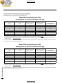
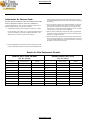
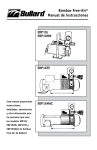
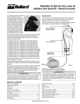
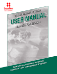
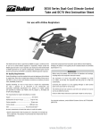
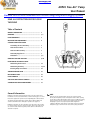
actoolsupply.com
ADP20 Free-Air® Pump
User Manual
Bullard ADP20 Free Ambient Air Driven Pump Respirator Supply System
Read all instructions before using
this PUMP
Table of Contents
GENERAL INFORMATION ............................................ 1
WARNINGS .............................................................. 3, 4
PUMP COMPONENTS .................................................. 5
BREATHING AIR REQUIREMENTS ................................ 6
ASSEMBLY AND INSTALLATION
Assembling the Free-Air Pump ........................... 7
How Air Motor Works ......................................... 7
How Motor Drives Pump ..................................... 7
How Pump Supplies Air ..................................... 7
Installation ...................................................... 7, 8
OPERATING THE FREE-AIR PUMP ................................ 9, 10
MAINTAINING THE FREE-AIR PUMP
Maintaining the Air Motor .................................. 11
Maintaining the Pump ....................................... 11, 12
Ensuring Pump Performance ............................... 12
TROUBLESHOOTING GUIDE ........................................ 13
REPLACEMENT PARTS ................................................ 14
PUMP WARRANTY ..................................................... 15
Air Filter Replacement Schedule ......................... 16
AUTHORIZATION FOR RETURNED GOODS ..................... 17
General Information
Bullard Free-Air Pumps transfer ambient air from a clean air location, where
breath-able air can be assured at all times, to workers wearing Type C or CE continuous flow supplied-air respirator hoods or tight fitting half or full face masks.
The ambient air is filtered through a medium efficiency Inlet Air Filter and a
Carbofine Outlet Filter before entering the respirator’s air supply hose.
Bullard Free-Air Pumps are oil-less and have rotary carbon vanes. They produce
no carbon monoxide, oil vapors, oil mist or moisture. They do not require expensive carbon monoxide monitors, high temperature alarms or airline filters. No
calibration is required.
Note
Drive-Air pressure (psig) determines horsepower of air motor which
directly affects output air pressure and output air volume. When operating
a hood-style respirator with a Frigitron 2000 Series air conditioner incoming
drive air pressure must be set at 95 psig for optimum pump performance.
Attempting to operate a hood-style respirator with a Frigitron air
conditioner with the incoming drive air at less than 95 psig may result in an
inadequate supply of air to the worker. See below for pump performance.
actoolsupply.com
actoolsupply.com
On the charts below, find the relevant Output Air Pressure (psig) corresponding to the
respirator’s approved pressure range to determine the pump’s total air volume (cfm)
and a maximum number of respirators that can be used at that air volume.
Model ADP20 Pump Performance Table
Incoming Drive-Air Pressure Maintained at 85 psig
Maximum Recommended
Mask Respirators**
Maximum Recommended
Hood Respirators**
Recommended Hood
Respirators with Frigitron
Air Conditioner
24.0
Five
Three
None
18.0
Three
Two
None
Pump’s Output Air Pressure
(psig)
Pump’s Output Air Volume
(cfm)*
5
10
15
14.0
Two
One
None
18
11.0
Two
One
None
20
8.5
One
One
None
22
7.0
One
None
None
25
4.0
None
None
None
* Assumes that no air is being dumped from the pressure relief valve and that pump’s drive-air pressure is maintained at 85 psig.
** It should be noted that the minimum air flow required for each tight-fitting, mask-style respirator is four (4) cfm. A minimum airflow of six (6) cfm is required for each
hood-style respirator.
The ratings which appear here, therefore, are conservative, but reflect Bullard Company’s position that worker respiratory protection is enhanced when air flow available to
the respirator wearer is above the NIOSH required minimums.
General Information
Model ADP20 Pump Performance Table
Incoming Drive-Air Pressure Maintained at 95 psig
Pump’s Output Air Pressure
(psig)
Pump’s Output Air Volume
(cfm)*
Maximum Recommended
Mask Respirators**
Maximum Recommended
Hood Respirators**
Recommended Hood
Respirators with Frigitron
Air Conditioner
5
31.0
Six
Four
None
10
26.5
Five
Three
None
15
21.5
Four
Three
None
18
18.5
Three
Two
One
20
16.5
Three
Two
One
22
14.5
Three
Two
One
25
11.4
Two
One
One
* Assumes that no air is being dumped from the pressure relief valve and that pump’s drive-air pressure is maintained at 95 psig.
** It should be noted that the minimum air flow required for each tight-fitting mask style respirator is four (4) cfm. A minimum airflow of six (6) cfm is required for each
hood-style respirator.
The ratings which appear here, therefore, are conservative, but reflect Bullard Company’s position that worker respiratory protection is enhanced when air flow available to
the respirator wearer is above the NIOSH required minimums.
2
actoolsupply.com
actoolsupply.com
ADP20 Free-Air® Pump
User Manual
� WARNING
READ ALL INSTRUCTIONS IN THIS MANUAL BEFORE USING FREE-AIR PUMP MODEL ADP20.
FAILURE TO OPERATE THIS PUMP IN ACCORDANCE WITH THE INSTRUCTIONS CONTAINED IN THIS MANUAL MAY RESULT IN DEATH OR SERIOUS INJURY TO THE
RESPIRATOR WEARER.
1. Locate the pump’s inlet air filter in a place where there is clean, breathable air at all times. The pump WILL NOT remove toxic gases or
other contaminants from the incoming air it transfers to the respirator wearer.
See the BREATHING AIR REQUIREMENTS section on page 4 for specific details on breathing air quality.
2. This pump will supply at least the required minimum volume of air (6 cfm for hoods or 4 cfm for tight fitting masks) to low pressure,
airline respirators. The respirators must be approved by MSHA/NIOSH to operate at less than 25 psig.
Be sure that the pump’s outlet pressure, measured by the pressure gauge on the pump, is maintained above the minimum pressure setting
required by the respirator manufacturer.
To be assured your respirator can be used with this pump, refer to the section in the respirator’s Instruction Manual for the respirator’s
approved pressure range and permissible air supply hose length.
If you have any questions about whether or not your respirator is compatible with this pump, contact Bullard’s customer service
department at 877-bullard.
3. Airline respirators used with this pump must not be worn in any atmosphere immediately dangerous to life or health or from which the
wearer cannot escape without the use of the respirator.
4. When connecting your respirator to the Free-Air Pump, use only the air supply hose and couplings required by the respirator manufacturer
and approved by MSHA/NIOSH.
Use of non-approved hose or couplings will void the respirator’s MSHA/NIOSH approval and could reduce the air flow to the respirator,
resulting in possible death or serious injury to the respirator wearer.
5.DO NOT modify or alter this pump in any manner. Use only approved Bullard Free-Air pump components and replacement parts on the pump.
Failure to use approved Bullard components and replacement parts invalidates all Bullard warranties and may result in death or serious
injury to the respirator wearer.
6. If you have any questions concerning the use of this pump or your respirator, or you are not sure the inlet air filter is located at
a source of clean, breathable air, ask your supervisor.
All instructions for the use and care of this product must be supplied to you by your employer as recommended by the manufacturer and as
required by Federal Law (29 CFR 1910.134).
Warnings
3
actoolsupply.com
actoolsupply.com
Model Adp20 Pump Components
Breathing Air Requirements
Air Quality
The Free-Air pump’s inlet air filter must be located in a place where there is clean,
breathable air at all times.
1
The breathable air drawn into the inlet filter must meet at least the requirements
for Type 1 gaseous air described in the Compressed Gas Association Commodity
Specifications G-7.1 (Grade D or higher), as specified by Federal Law 30 CFR, Part 11,
Subpart J, 11.121 (b).
The requirements of Grade D breathable air include:
2
- Oxygen.............................................................................. 19.5 - 23.5%
- Hydrocarbons (condensed) in mg/m3 of gas................. 5 mg/m3 maximum
- Carbon Monoxide............................................................. 10 ppm maximum
- Carbon Dioxide................................................................. 1,000 ppm maximum
- Odor.................................................................................. No detectable odor
- No toxic contaminants at levels which would make the air unsafe to breathe.
Refer to the C.G.A. Commodity Specification G-7.1 for complete details. It is available from:
17
6
4
7
3
Pump Components / Breathing Air Requirements / Assembly & Installation
Compressed Gas Association
500 Fifth Avenue
New York, NY 10036
5
8
18
9
10
Assembly and Installation
For the specific location of the pump components referred to below, see the list of
pump components to the left.
Assembling the Free-Air Pump
1. Remove assembly from plywood shipping board and attach four rubber feet
through four holes in skid.
2. Install stand pipe (2), and Inlet AIR Filter (1) into threaded air inlet PORT (3).
3. Make sure the pump’s inlet air filter is located in a clean, uncontaminated location
where breathable air is assured at all times.
16
15
14
13
12
11
If the inlet air filter cannot be placed at a source of clean, breathable air, install
Bullard’s 50 foot Inlet Extension Hose Kit (Cat. No. V50IN) to the pump’s inlet port.
See the directions shipped with the Extension Hose Kit for assembly instructions.
If clean breathable air cannot be guaranteed at all times within this 50 foot
reach, you may add up to five additional lengths of 50 foot Extension Hose (Cat.
No. V50EX).
1. Inlet Air Filter 23611
2. Air Inlet Stand Pipe
3. Threaded Air Inlet Port
4. Gauge, Drive Air Pressure (0-200 psig) S09853
5. Gauge, Outlet Air Pressure (0-30 psig) S16222
6. Outlet Filter Cartridge S17101
7. Heat Exchanger
8. Quick-Disconnect Couplers, Female (1/2” industrial interchange) S16191
9. Air Motor
10. Throttle Valve
11. Plug
12. Lubricator
13. Oil Metering Screw
14. Oil Sight Dome
15. Pressure Regulator
16. Drive Air Inlet Claw Foot Connector
17. Regulator Knob
Therefore, you may place your Inlet Filter up to 300 feet (6 x 50) away from the
pump. Do not add more than 300 feet of inlet extension hose to the pump.
How Air Motor Works
1. Compressed air enters through drive Air Inlet (16), passes through pressure
regulator (15); where pressure is controlled and excess oil and water are
removed.
Air pressure is adjusted with REGULATOR KNOB (17) and is read on GAUGE (4)
(NOTE: 80 psig or higher during operation is normal for this motor).
2. Air passes through LUBRICATOR (12) where oil is added and metered.
3. Lubricated air passes through THROTTLE VALVE (10) and drives AIR MOTOR (9)
4. Air is exhausted through motor exhaust muffler (18) to atmosphere.
How Motor Drives Pump
Motor drives pump through a flexible coupler. There are no belts to maintain or tighten.
How Pump Supplies Air
Clean breathable air must be supplied to PUMP INLET AIR FILTER (1) at all times (See
Breathing Air Requirements in the section above).
The pump draws in air using four sliding carbon vanes set in a rotor, and discharges it
under low pressure out of discharge port.
4
actoolsupply.com
actoolsupply.com
ADP20 Free-Air® Pump
User Manual
Air passes through Bullard’s CARBOFINE OUTLET FILTER CARTRIDGE (6) located
inside OUTLET FILTER HOUSING.
Bullard’s CARBOFINE outlet filter is triple wrapped with activated carbon media and
has a rayon overwrap.
The properties of this filter include:
•STOPS 99.97% ALL OIL AEROSOLS
•99.97% D.O.P. EFFICIENCY (.3-.6 MICRON SIZE PARTICLES)
•MAXIMUM SOLID PARTICLE SIZE THAT WILL PASS THROUGH 0.3 MICRON
•MAXIMUM LIQUID PARTICLE SIZE THAT WILL PASS THROUGH 0.75 MICRON
As long as the customer has Grade D air going into the pump and the inlet and outlet
filter are clean the pump should be working correctly and adheres to what is required.
NOTE: Change this outlet filter cartridge at least every 200 running hours.
Filtered breathing air passes out through one, two, or three couplers (8) to one,
two, or three airline respirators depending on the style of respirator(s) being used
(See table, page 2).
Note: The two, 1/2” Industrial Interchange quick-disconnect couplers are
supplied with the factory packed unit. You may replace these couplers to
conform with the hose and respirator you are using.
Installation
NOTE: Use ample size hose from compressor to pump; 1” or 3/4” internal
diameter is best. A larger diameter compressed air hose may be required
depending on operating conditions and length of compressed air line.
The compressor must have capacity to continuously supply at least 85 cfm of air at
95 psig to drive the pump at its rated capacity.
1. With the pump shut off, fill LUBRICATOR (12) through fill cap with SAE 10
Automotive Engine Oil to fill line on bowl. Do not use a heavier grade oil than
SAE 10. Be sure drain valve at bottom of regulator is closed
2. Close THROTTLE VALVE (10).
3. ATTACH HOSE WITH RESPIRATORS CONNECTED TO AIR OUTLETS (8) ON PUMP.
4. Connect air supply to pump.
5. Adjust AIR REGULATOR so COMPRESSED AIR GAUGE (4) reads 95 psig.
6. Pump is ready to run. Open THROTTLE VALVE (10), build up speed and idle for
a few minutes.
7. Adjust THROTTLE VALVE (10) to run pump at desired psig on OUTLET AIR
PRESSURE GAUGE (5) and adjust OIL METERING SCREW (13) until lubricator
is producing approximately 1 DRIP PER MINUTE in the SIGHT DOME (14).
NOTE: This drip rate should be monitored occasionally during operation.
8. Adjust RELIEF-VALVE as follows:
NOTE: The relief valve is preset at the factory to “bleed off” at 25 psig.
a. Loosen lock nut.
b. Pinch off respirator air supply hose to create back pressure.
c. Speed up motor by opening throttle valve.
� WARNING
THE RESPIRATOR USER MUST NOT ENTER THE CONTAMINATED WORK AREA
UNTIL ALL OF THE FOLLOWING STEPS HAVE BEEN COMPLETED.
1. Analyze the atmosphere at the location of the pump’s air inlet filter. The inlet
filter should be located in a clean, uncontaminated location where breathable
air is assured at all times. The pump is equipped with a 2 ft. stand pipe to
keep the intake away from the air motor exhaust port.
If the inlet filter cannot be placed at a source of clean, breathable air,
install Bullard’s 50 foot Inlet Extension Hose Kit (Cat. No. V50IN) to the
pump’s inlet port. See the directions shipped with the Extension Hose Kit for
assembly instructions.
If clean breathable air cannot be guaranteed at all times within this 50 foot
reach, up to five (5) additional lengths of 50 foot Extension Hose (Cat. No.
V50EX) may be added.
Therefore, the inlet filter may be placed up to 300 feet (6 x 50) away from the
pump. Do not add more than 300 feet of inlet extension hose to the pump.
2. Be sure you have read and followed all instructions for assembly and
installation of the ADP20 pump on pages 4 and 5.
3. Pump Model ADP20 will operate sitting on its four rubber mounts. It does not
need to be bolted down.
4. Assemble your respirator by following the manufacturer’s directions as
described in the respirator’s Instruction Manual. Be sure the pump’s outlet
pressure, measured by the pressure gauge on the pump, is greater than the
minimum MSHA/NIOSH approved pressure required to operate the respirator.
The respirator’s minimum approved pressure will be found in the respirator’s
Instruction Manual and/or on labels attached to the respirator.
If you have any questions as to whether or not your respirator is compatible
with this pump, call Bullard’s Customer Service Department at 877-BULLARD.
5. Connect the respirator’s MSHA/NIOSH-approved air supply hose(s) to the
quick-disconnect Outlet Coupling(s) on the pump.
A. Outlet Coupling
If your respirator’s air supply hose(s) have 1/2” Industrial Interchange quickdisconnect fittings and you want to supply air to one or two hood, full face or half
maskrespirators you may connect them directly to the two female 1/2” quickdisconnectcouplers on the pump.
If you want to supply air to three full or half mask respirators (the pump does not
provide sufficient air volume for three hoodstyle respirators), you may purchase
andinstall an additional female quick-disconnect coupling (Cat. No. S16191).
B.Connecting Air Supply Hose(s) without 1/2”
Quick-Disconnect Fittings
f. Maximum output operating pressure is 25 psig.
If your respirator’s MSHA/NIOSH-approved air supply hose will not attach to the
pump’s standard 1/4” Industrial Interchange Outlet Couplings, (see above) the hose
fitting can be adapted to the pump by converting the pump’s quick-disconnect outlet
to 3/8” female NPT with the installation of one or more of the following adaptors.
NOTE: Pump will reach 150° - 200° F during normal running conditions.
Cat. No. V23 - Converts SINGLE outlet to SINGLE 3/8” female NPT pipe thread.
e. Slow down motor and check that no air “bleeds” below required pressure.
Lock nut
Use Teflon tape or pipe thread sealer to ensure an air tight seal.
A variety of quick-disconnect fittings may then be used to connect the air supply
hose to the 3/8” outlet adaptor. Contact your respirator’s manufacturer for the
proper fitting (Hansen, Parker, Snap-Tite, Schrader, etc.)
6. Before connecting your respirator to the air supply hose, turn the pump
on. Allow the air to flow through the pump and hose for a few minutes to
purge or expel any hose odors or moisture that may have accumulated
inside the hose.
Operating the Free-Air Pump
d. Adjust relief-valve to “bleed off” at a pressure 1 or 2 psig above that
required by respirator.
Operating the Free-Air Pump
Relief valve
5
actoolsupply.com
actoolsupply.com
7. Connect the respirator to the air supply hose using the quick-disconnect fittings.
8. Set the pump’s outlet pressure to within the respirator’s approved pressure
range by adjusting the Throttle Valve (10).
9. With the air flowing, put on the respirator by following the directions in the
respirator manufacturer’s Instruction Manual.
YOU ARE NOW READY TO ENTER THE WORK AREA.
10.When finished working, leave the work area wearing the respirator with the air
still flowing. Once outside the contaminated area, remove the respirator, turn the
pump off, then disconnect the air supply hose using the quick-disconnect couplings.
See the respirator’s Instruction Manual for proper inspection, maintenance
and storage procedures for the respirator you are using.
2. Flush PUMP if necessary
Should dirt, foreign particles, moisture or oil be permitted to enter, the vanes
will become sluggish, resulting in a lowering of outlet air pressure. Flush the
pump with LOCTITE Safety Solvent. (DO NOT USE KEROSENE).
Pump should be operated for at least a few minutes every one to two weeks
to reduce the likelihood of rust film forming in the rotor.
If pump remains idle in humid environment for some time, FLUSHING may be
required to remove rust film in chamber and rotor slots.
Use the following directions to flush pump:
a. Turn-off Throttle Valve (10) to stop the pump before flushing.
Maintaining the Free-Air Pump
For the pump to operate at its optimum performance level, the
following routine maintenance procedures must be performed.
FOR THE SPECIFIC LOCATION OF THE PUMP COMPONENTS REFERRED TO
BELOW, SEE THE LIST OF PUMP COMPONENTS ON PAGE 4.
Maintaining the Air Motor
The air motor is a rotary 4-vane type. The vanes require no adjustment and will last
5,000-15,000 hours if properly maintained.
1. Maintain INLET AIR PRESSURE REGULATOR FILTER (15):
- It is equipped with a 40-micron filter element that can plug up if air supply is
not prefiltered at the compressor.
- Remove and clean filter periodically to prevent clogging.
b. Before flushing, disassemble and remove the following parts from the pump:
- Respirator air supply hose(s)
- Inlet Filter and Pipe Stand
- Outlet Filter Jar and Outlet Filter
c. With the pump running, pour several teaspoons of solvent into the pump’s
inlet port. Repeat the flushing if necessary.
� WARNING
Run the pump for a sufficient time to purge all traces of the solvent
before replacing the filters, reconnecting the air supply hose(s)
and using the respirator.
3. AVOID EXCESSIVE SPEEDS and PRESSURE
2. Maintain LUBRICATOR (12):
- Keep filled with SAE 10 Automotive oil. (Do not use a heavier grade)
- Avoid running above the 25 psig range for any length of time.
- Maintain drip rate at approximately 1 per minute.
NOTE: NEVER lubricate this oil-less pump. BEARINGS are grease packed
and sealed. They require no further lubrication.
- DO NOT fill while running or while under pressure
Ensuring Pump Performance
3. Flush MOTOR (9):
Maintaining the Free-Air Pump / Troubleshooting Guide
motor speeds up or the outlet pressure shown on GAUGE (5) increases, the
filter needs replacement.
If motor is sluggish or inefficient, flush with LOCTITE Safety Solvent, or any
non-toxic, nonflammable industrial cleaning solvent).
Use the following directions to flush the motor:
a. Shut-off the pressure into the air motor and disconnect the airline from the
Drive Air Inlet (16).
b. Locate the pump in a safe area. Solvent will spray from the exhaust port
during flushing. Protect your face and eyes from the spray.
c. Remove the Plug (11) and pour several teaspoons of solvent into the opening.
d. Replace the Plug, reconnect the airline back to the Drive Air Inlet. Turn
the pressure back on. Run the pump at a very low speed (10-20 RPM) for
approximately one minute or until all the solvent is flushed.
NOTE: Motor bearings are grease packed and sealed. They require no
maintenance.
To make sure your pump will perform properly:
1. Always locate the pump’s air inlet in a clean, breathable air environment.
2. DO NOT contaminate inlet air with exhaust air from air motor
3. Change OUTLET FILTER every 200 running hours.
4. Make sure RELIEF VALVE is fully seated (no bleed-off).
5. Make sure LUBRICATOR is full and is functioning (1 drop per minute).
6. Always check Respirator Air Supply Hoses to make sure they are free of kinks.
7. Set incoming compressed drive air at 85 psig or higher. Set output air pressure
as specified in respirator owner’s manual.
Maintaining The Pump
See charts on pages 1 and 2 for pump performance. If operating hood with Frigitron
2000 Series air conditioner, incoming compressed driven air must be set at 95 psig
or higher.
Pump is rotary 4 vane type. The vanes require no adjustment and will last 5,000 to
10,000 hours if properly maintained.
Troubleshooting Guide
1. Maintain FILTERS
- Dirty filters restrict outlet air flow and can cause the motor to overload or
cause premature pump failure.
- Replace CARBOFINE OUTLET FILTER CARTRIDGE (6) at least once every 200
running hours (Catalog No. S17101).
- Replace INLET FILTER (1) at least once every 500 running hours to maintain
proper pressure and full air flow. To check the filter - while running the
pump, momentarily remove the FILTER (1) from the Inlet PIPE (2). If the
OUTLET PRESSURE TOO HIGH
- Adjust THROTTLE VALVE (10)
- Check for kinked air supply hoses
- Reset pressure adjustment valve
OUTLET PRESSURE too low
- Adjust THROTTLE VALVE to increase motor speed
- Check for clogged INLET FILTER
6
actoolsupply.com
actoolsupply.com
ADP20 Free-Air® Pump
User Manual
Pump Warranty
- Check that outlet filter jar is screwed on tight
- Check for clogged OUTLET FILTER
Free-Air Pump One Year Limited Warranty
- Check pressure relief valve and adjust if necessary
- Check drive air inlet pressure
- Check for leaks in air hose
- Verify proper pressure range for your respirator
- Verify that respirator and hose are connected when gauge reading is taken
- Check to see that gauge is functioning properly
- Flush pump with Loctite Safety Solvent
RESPIRATOR AIR TEMPERATURE too high (above ambient)
- Air supply hoses coiled too tightly. Uncoil at least the first 50 feet of hose.
- Place portion of air supply hose in large container of ice (e.g. 30 gallon trash can).
- Keep air supply hoses out of direct sunlight or other heat sources.
Replacement Parts
Cat. No.
Description
V50EX
S17931
Remote INLET air hose kit (50 feet) with remote inlet filter and pump fittings
Extension hose kit (50 foot sections) for above
LOCTITE Safety Solvent (pump or motor)
NOTE: If breathable air cannot be assured at all times at the pump, remove
inlet filter and attach necessary V50 hose kits to air inlet port. Use up to 300
feet (six lengths) always ending with V50IN kit. These hose kits can provide
access to a remote “clean air” location.
V23
V19
V23
S16191
Gauge, Air (0-30 psig)
Bullard CARBOFINE outlet filter cartridge
Inlet filter
Outlet filter jar (aluminum jar only)
Outlet filter assembly o-ring (10 per pkg.)
Conversion kit
Coupler, 1/4” Industrial Interchange, with male 3/8” NPT
Quick disconnect
Coupler, 1/4” Snap-Tite with 1/4” female pipe thread FPT
Quick-disconnect coupling adaptor, SINGLE 3/8”
female NPT
Coupler, 1/2” Industrial Interchange, with 3/8” male NPT
Pump repair kit (includes four carbon vanes, one 23611 inlet filter, one S17101 outlet filter cartridge and instructions
AIR MOTOR REPLACEMENT PARTS
S09853
17761
In no event shall Bullard be responsible for damages for loss of use or other
indirect, incidental, consequential or special costs, expenses or damages incurred
by the purchaser, notwithstanding that Bullard has been advised of the possibility
of such damages.
Some states do not allow the exclusion or limitation of incidental or consequential
damages, or allow limitations on how long an implied warranty lasts, so the above
limitations or exclusions may not apply to you. This warranty gives you specific
legal rights, and you may have other rights which vary from state to state.
TO RETURN GOODS: Written permission must be obtained before returning any
material for any reason whatsoever (See Authorization for Returned Goods on
page 8).
Gauge (0-200 psig)
Motor repair kit (includes four carbon vanes, two motor bearings, vane springs, seal and instructions)
NOTE: Pump and motor repair requires use of a 3-prong wheel puller, a gear
puller and an experienced mechanic. It may be quicker and less expensive to
ship pump and/or motor to Bullard for repairs. See Authorization for Returned
Goods, page 8)
Air Filter Replacement Schedule
Regular inspection and replacement of the air filters will prevent extensive and
costly pump repairs. Dirty or clogged filters can be responsible for failure of the
pump to build up outlet pressure and eventual overheating.
- Replace the Carbofine Outlet Filter Cartridge (Cat. No. S17101) at least once
every 200 running hours or sooner if necessary.
The Outlet Filter Cartridge is multi-layered with 40-micron size particles of
activated carbon, a sorbent bed with an exposed carbon surface of more than
15,000 square feet.
•Vapor Removal Efficiency: 90-95%
•D.O.P. Efficiency: (0.3 to 0.6 Micron Particles) 99.97%
•Solid Particle Filtering: 0.2 Micron and Larger.
•Liquid Particle Filtering: 0.75 Micron and Larger
- Replace the medium efficiency Inlet Filter (Cat. No. 23611) at least once every
500 running hours or sooner if necessary.
The Inlet Filter keeps moisture as well as particulates larger than 25 microns
out of the air supply and helps protect the pump’s carbon vanes.
We recommend the chart on the back page be used to monitor and maintain a
routine air filter replacement schedule.
Warranty / Replacement Schedule
S15922
c) The date of purchase is the start of the one year warranty period. (A copy of
the purchaser’s original invoice showing the date of purchase is required to
validate warranty coverage.)
Products which are obsolete or made to special order may not be returned.
REPLACEMENT PUMP PARTS
S16222
S17101
23611
244852
263552
21052
V15
b) Free-Air Pump must not have been misused, subjected to negligent use, or
damaged in transport.
ANY IMPLIED WARRANTIES, INCLUDING WARRANTIES OF MERCHANTABILITY
AND FITNESS FOR A PARTICULAR PURPOSE, ARE LIMITED IN DURATION TO
ONE (1) YEAR FROM THE DATE OF PURCHASE OF THIS PRODUCT.
OPTIONAL PUMP ACCESSORIES
V50IN
The Bullard warrants to the original purchaser that the Free-Air Pump will be free
of defects in material and workmanship under normal use and service for a period
of one (1) year from the date of purchase. Bullard’s obligation under this warranty
is limited to repairing or replacing, at its option, articles that are returned within the
warranty period and that are, after examination, shown to Bullard’s satisfaction to
be defective, subject to the following limitations.
a) Free-Air Pump must be returned to the Bullard factory with shipping
charges prepaid.
7
actoolsupply.com
actoolsupply.com
Authorization for Returned Goods
IMPORTANT: BULLARD WILL DECLINE TO ACCEPT ANY RETURNED GOODS SHIPMENT
UNLESS YOU HAVE FIRST FOLLOWED ALL OF THE STEPS OUTLINED BELOW.
To return goods to Bullard for repair, or replacement, whether under the terms of
Bullard’s warranty provisions or for paid repairs, you MUST:
1. Contact Bullard’s Customer Service Department by telephone or in writing
Describe the nature of the problem you are experiencing. A Bullard Customer
Service Representative may contact you for additional information or may
attempt to help you resolve the problem over the telephone.
include information which must be included on the shipping carton for proper
receiving and handling by Bullard. DO NOT return product without first following
this procedure.
3. Prior to packing the product for return shipment to Bullard, be certain that
it has been fully decontaminated and cleaned of any hazardous materials
which may have settled on the product during use. It is against the law to
ship hazardous or contaminated materials. Bullard may refuse to accept the
return of any product suspected of being contaminated.
4. Products returned, including those under warranty, must be shipped with all
transportation charges prepaid. Bullard cannot accept any returned products
delivered on a “freight-collect” basis.
5. Material returned will be subjected to factory inspection. Repair work that is
deemed necessary, but which is not covered by warranty, will be performed at
your expense. Bullard will attempt to provide a best estimate of such charges,
but will invoice based upon work performed.
2. Upon determining that the product should be returned, Customer Service will
provide you with written permission to return the product to Bullard. This will
Routine Air Filter Replacement Schedule
CARBOFINE OUTLET FILTER CARTRIDGE
(Cat. No. S17101)
Cumulative Pump
Operating Hours
Last Filter
Replacement Date
MEDIUM EFFICIENCY INLET FILTER
(Cat. No. 23611)
Employee Responsible
(Initials)
Pump Operating Hours
200
500
400
1,000
600
1,500
800
2,000
1,000
2,500
1,200
3,000
1,400
3,500
1,600
4,000
1,800
4,500
2,000
5,000
actoolsupply.com
Cumulative Last Filter
Replacement Date
Employee Responsible
(Initials)