1
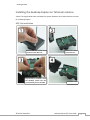
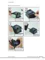
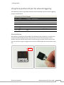
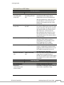
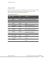
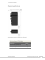
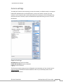
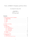
GeoSnap Express
(Tetracam) User Guide
Date
Revision
6/19/15
Manual created
Contents
Introduction ..........................................................................................................................1
The GeoSnap Express ................................................................................................................... 2
System components..................................................................................................................... 3
Getting Started ......................................................................................................................5
Installing the GeoSnap Express on Tetracam cameras ................................................................ 6
Using the 6-position I/O port for external triggering................................................................... 9
Powering the GeoSnap system .................................................................................................. 10
LED codes ................................................................................................................................... 10
Loading new firmware onto the GeoSnap system..................................................................... 12
GeoSnap System Files .......................................................................................................... 13
Configuration file ....................................................................................................................... 14
Flight data log file....................................................................................................................... 21
Image log file .............................................................................................................................. 23
Troubleshooting .................................................................................................................. 24
Frequently asked questions ....................................................................................................... 25
Specifications & Settings ...................................................................................................... 26
Physical specifications................................................................................................................ 27
Power specifications .................................................................................................................. 28
6-position I/O port specifications .............................................................................................. 28
MicroSD card specifications ....................................................................................................... 28
Camera settings ......................................................................................................................... 29
© Field of View 2014
GeoSnap Express (TC) User Guide
iii
Introduction
In this section:
•
•
The GeoSnap Express
System components
© Field of View 2014
GeoSnap Express (TC) User Guide
1
Introduction
The GeoSnap Express
The Field of View GeoSnap system was developed to integrate with cameras to streamline
integration, facilitate intelligent triggering, and produce a valuable log of position/attitude
conditions at the moment of image capture.
© Field of View 2014
GeoSnap Express (TC) User Guide
2
Introduction
System components
*Note: these images are for the GeoSnap Pro system so there are a few differences but the
ports/interfaces are the same between the Pro and the Express.
GeoSnap Control Unit
6-position I/O port
Power input
MicroSD card slot
Onboard button
ADC Lite/Micro/Snap Accessories
GPS antenna
MicroSD card adapter
Velcro mounting patch
© Field of View 2014
6-position I/O wires (2)
2-position housing/spare pins
Power pigtail
GeoSnap Express (TC) User Guide
3
Introduction
Mini-MCA Accessories
GPS antenna
MicroSD card adapter
© Field of View 2014
Velcro mounting patch
6-position I/O wires (2)
GeoSnap Express (TC) User Guide
4
Getting Started
In this section:
•
•
•
•
•
Installing the GeoSnap Express on Tetracam cameras
Using the 6-position I/O port for external triggering
Powering the GeoSnap system
LED codes
Loading new firmware on the GeoSnap system
© Field of View 2014
GeoSnap Express (TC) User Guide
5
Getting Started
Installing the GeoSnap Express on Tetracam cameras
*Note: The images below show a GeoSnap Pro system. However, the method remains the same
for a GeoSnap Express.
ADC Lite installation
Remove the four screws from
the back of the ADC Lite
Remove the back
of the ADC Lite
Plug the 15-pin connector from
the GeoSnap system into the
corresponding slot on the ADC
Twist the cable
© Field of View 2014
GeoSnap Express (TC) User Guide
6
Getting Started
Place the ADC Lite back containing
the GeoSnap system on the camera
© Field of View 2014
Screw in the two screws on the
GeoSnap system case and replace
the other two screws on the camera
GeoSnap Express (TC) User Guide
7
Getting Started
ADC Micro/Snap installation
Align and place the
double-sided tape on
the camera shown
Plug the 15-pin connector
from the GeoSnap system
into the port on the camera
Remove the backing from
the double-sided tape
Twist the cable
Stick the GeoSnap
system onto the side of
the camera as shown
© Field of View 2014
GeoSnap Express (TC) User Guide
8
Getting Started
Using the 6-position I/O port for external triggering
The 6-position I/O port can be used to interface with the GeoSnap system to control triggering
using an external source.
6-Position I/O Port Pinout
Pin
1
2
3
4
5
6
Label
Voltage
Ground
RS232-in
-15 to 15V
RS232-out
-15 to 15V
Trigger
0 to 5V
Trigger power 3.3V
VCC
3.3V
Description
Not currently operational
Not currently operational
Control GeoSnap by driving this line high or low
VCC line for external triggering
-
Wire installation
Wires with pre-crimped pins are provided in the GeoSnap system accessories. To install a wire
into the 6-position locking connector, place the wire into one of the empty slots in the 6position connector with the smooth side of the pin facing up as shown. Push the wire in until
you hear a click then tug on it slightly to ensure that it seated. Repeat this with the other empty
slot.
Triangle signifies
position 1
Position numbers
© Field of View 2014
GeoSnap Express (TC) User Guide
9
Getting Started
Triggering
The GeoSnap board can be triggered externally by an autopilot or other input by driving the
Trigger line (position 4) high (3.3-5V) or low (0-0.2V), depending on the settings you have chosen
in the configuration file. It is highly recommended that you use the GeoSnap system Trigger
Power line (position 5) to provide the voltage to hold or drive the Trigger line high. Triggering
using the Trigger line and the Trigger Power line can be accomplished by shorting the two wires
together or by using a PWM relay to control voltage level.
Powering the GeoSnap system
When using the GeoSnap system with an ADC Lite or the ADC Micro/Snap, the camera is
powered through the GeoSnap system, but you need to power the GeoSnap system from an
external source such as a battery or autopilot. A power pigtail with a 2-position connector is
provided in the GeoSnap system accessories for this purpose. An extra 2-position locking
connector and extra pins are also provided if you want to make your own power wire harness.
GeoSnap Express (TC) Power Requirements
Parameter
Voltage input range
Current input (when powering
ADC Lite, Micro, or Snap)
Current input (GeoSnap only)
Value
9 to 15 V
0.35 A
0.1 A
When using the GeoSnap system with a Mini-MCA, the GeoSnap system is powered from the
Mini-MCA so you need to power the camera per Tetracam’s instructions.
LED codes
The meanings of the LEDs on the GeoSnap board are explained in this section.
• Blue LED – This LED indicates when the board is powered. When power is sent to the
board, this LED shines solid.
• Red LED & Green LED – These LEDs indicate the status of the GeoSnap system including
startup status, GPS status, triggering, and camera capture indications.
A detailed description of the LED sequences and their meanings are presented below.
© Field of View 2014
GeoSnap Express (TC) User Guide
10
Getting Started
Red and Green LED Codes
Startup Sequence
Red LED
Flashing slowly,
alternating with
Green LED
Green LED
Flashing slowly,
alternating with Red
LED
Flashing slowly with
Green LED
Flashing slowly with
Red LED
Flashing slowly
Flashing quickly
Solidly lit with Green
LED
Solidly lit with Red
LED
Meaning
Board is checking for access to the
microSD card and writing a default
CONFIG file to the card if a CONFIG file
does not already exist. *Note: this is also
the LED code for an SD card error (see
below) so if this pattern persists, check
the SD card.
Board is waiting for a serial message from
the camera indicating the camera is ready
to start operating. If no signal is received
after approximately 30 seconds (for the
ADC cameras) or 2 minutes (for the
Micro-MCA) the board moves on to the
next step (if this occurs, check to make
sure the baud rate of the camera and the
GeoSnap match).
The GeoSnap system is ready to start
operating. If the GeoSnap system is
configured for fast as possible or time
based triggering, the first trigger
command will be sent at this point
GPS receiver has a lock. If the GeoSnap
system is configured for distance based
triggering, and no altitude limit is set, the
first trigger command will be sent 10
seconds after lock is obtained.
This occurs after pressing and holding the
trigger button for approximately 3
seconds. This signifies that all data logging
has stopped and it is safe to power down
the system.
Capturing Images
Red LED
Quick double flash
Illuminates
synchronously with
shutter release
© Field of View 2014
Green LED
Meaning
A trigger command has been sent
The board is receiving the signal from the
camera that it captured an image
GeoSnap Express (TC) User Guide
11
Getting Started
Errors
Red LED
Flashing slowly,
alternating with
Green LED
Green LED
Flashing slowly,
alternating with Red
LED
Meaning
MicroSD card error. Occurs when there is
no card, the card is not seated properly,
the card is full, or if the log file number
exceeds 999.
Loading new firmware onto the GeoSnap system
If you need to load new firmware on your GeoSnap system, follow these steps:
1. Erase all data from the microSD card
2. Copy the firmware file (FOV.fwu) onto the microSD card and insert the card into the
GeoSnap system
3. Power the GeoSnap system – it will flash alternating red and green LEDs for a couple of
seconds until the firmware is loaded and it automatically erases the firmware file from
the microSD card
© Field of View 2014
GeoSnap Express (TC) User Guide
12
GeoSnap System Files
In this section:
•
•
•
Configuration file
Flight data log file
Image log file
© Field of View 2014
GeoSnap Express (TC) User Guide
13
GeoSnap System Files
Configuration file
Each time the GeoSnap system is powered, it searches for a configuration file named
CONFIG.TXT on the microSD card. This is a configuration file that contains options to customize
the operation of the GeoSnap system. If this file is not found, a new configuration file is created
with default options.
The file consists of human-readable ASCII text and can be edited using many types of text
editors. On Windows, either Notepad or Wordpad may be used. On OSX, TextEdit may be used.
On GNU/Linux or Unix, EMACS, Vim, Nano, Pico, or other graphical equivalents may be used.
Note: word processing software such as Microsoft Word should not be used to edit the
configuration file.
The first line of the CONFIG file displays which GeoSnap system firmware generated the file. The
sections below describe in detail the various settings and how their options/values affect the
behavior of the GeoSnap system.
*The GeoSnap system requires slightly different firmware for ADC Lite/Micro/Snap cameras and
the Micro-MCA cameras and a couple options in the configuration file are slightly different to
accommodate the specific requirements of the cameras.
© Field of View 2014
GeoSnap Express (TC) User Guide
14
GeoSnap System Files
GeoSnap system baud rate for communication with the Tetracam camera
Default String:
@2:TC_baud = 0
Values:
0:
1:
2:
3:
4:
115200 [default]
57600
38400
19200
9600
Description:
This option allows you to specify at what baud rate the GeoSnap system communicates with
the Tetracam camera. A matching baud rate must be manually configured on the camera. It
is strongly recommended that you use the default baud rate.
Suffix to be appended to the TTC image number in the GeoSnap system
image log
Default String:
@3:Image_suffix = 0
Values:
(different for ADC Lite/Micro/Snap and Micro-MCA)
Description:
This option allows you to specify what file extension will be appended to the image file
names. The options are designed to cover most situations however, if you need a different
naming convention, Geotility has a utility that will create a new image log file with your
specified image names.
Mode that determines when the GeoSnap system sends a trigger
command
Default String:
@4:Trigger_mode = 0
Values:
0:
1:
2:
3:
4:
5:
6:
onboard button only [default]
time
distance
fast-as-possible
low->high input signal
high->low input signal
low->high and high->low input signal
© Field of View 2014
GeoSnap Express (TC) User Guide
15
GeoSnap System Files
Description:
Set this option to specify the mode that the GeoSnap system will use to determine when to
send a trigger command. When this option is set to ‘onboard button only’ the GeoSnap can
only be commanded to send a trigger command when the trigger button onboard the
GeoSnap system is pushed. When this option is set to ‘time’ the GeoSnap will send trigger
commands at a uniform time interval that can be specified in the time interval option. When
this option is set to ‘distance’ the GeoSnap will send trigger commands at a uniform distance
interval (calculated from the latitude and longitude obtained from the GPS receiver) that
can be specified in the distance interval option. When this option is set to ‘fast-as-possible’
the GeoSnap will command a trigger immediately after receiving capture verification from
the camera resulting from the prior trigger command. When this option is set to any of the
input signal modes (options 4, 5, and 6), the GeoSnap will send a trigger command every
time the external input signal sends a voltage transition as listed in the option. For example,
if ‘low->high input signal’ is selected, the GeoSnap will send a trigger command every time
the external input signal transitions from low to high voltage (for more information on using
an external input signal, see the “Using the 6-position I/O port for external trigging”
section).
For mode 1 above, specify a time interval in seconds
Default String:
@5:Trigger_time_sec = 2.0
Values:
0.1 - 64800 seconds (in tenth of a second increments)
Description:
This option sets the amount of time (in seconds) between trigger commands sent by the
GeoSnap system when it is set to time mode triggering. This is configurable in tenth of a
second increments. The trigger mode must be set to 1 in order for this option to have any
effect on system operation.
For mode 2 above, specify a distance interval in meters
Default String:
@6:Trigger_dist_m = 50
Values:
1 - 10000 meters (in meter increments)
Description:
This option sets the distance (in meters) between trigger commands sent by the GeoSnap
system when it is set to distance mode triggering. This is configurable in meter increments.
© Field of View 2014
GeoSnap Express (TC) User Guide
16
GeoSnap System Files
Any decimals entered will be truncated. The trigger mode must be set to 2 in order for this
option to have any effect on system operation.
Length of time the GeoSnap system waits for capture verification from
the camera before resending the trigger command
Default String:
@7:Resend_trig_time_ms = 2500
Values:
0 - 60000 milliseconds
Description:
This option allows you to set the amount of time the GeoSnap waits for capture verification
before resending the trigger command. This value should be greater than or equal to the
cycle time of the camera. This option gives you control over your mission quality control by
allowing you to specify the amount of time to wait and see if the camera took a picture
before identifying a missed trigger and attempting to salvage the trigger point.
Use external input signal or onboard button to control time mode, fast-aspossible mode, and/or distance mode
Default String:
@8:Control_mode= 0
Values:
0: feature disabled [default]
1: high input signal enables time mode, fast-as-possible mode, or
distance mode
2: low input signal enables time mode, fast-as-possible mode, or
distance mode
3: onboard button starts time mode or fast-as-possible mode
4: onboard button toggles (starts/stops) time mode or fast-as
possible mode
Description:
This option allows you to use an external input signal to enable time mode, fast-as-possible
mode, or distance mode or to use the GeoSnap system onboard button to start and/or stop
time mode or fast-as-possible mode. If this feature is disabled and the GeoSnap system is in
time, or fast-as-possible mode, it will start sending trigger commands as soon as it is
powered. If this feature is disabled and the GeoSnap system is in distance mode, it will start
sending trigger commands as soon as a GPS lock is acquired.
© Field of View 2014
GeoSnap Express (TC) User Guide
17
GeoSnap System Files
If enabling with an input signal is selected (options 1 or 2), time mode, distance mode, or
fast-as-possible mode triggering, will only be allowed when the external input signal is held
high or held low (depending on the option selected). This is useful if images are only desired
during a certain portion of the flight.
If option 3 is selected, time or fast-as-possible triggering won’t start until the button is
pressed and subsequent button presses will be ignored. If option 4 selected, time or fast-aspossible triggering won’t start until the button is pressed and subsequent button presses
will stop and start the triggering.
Activate time mode or fast-as-possible mode when the GeoSnap system
detects an initial image capture
Default String:
@9:Initial_image_activation = 0
Values:
0: feature disabled [default]
1: feature enabled
Description:
This option configures whether to start time mode or fast-as-possible mode triggering after
an initial camera image capture has been detected by the GeoSnap system. With option 1
set, triggering won’t start until the GeoSnap system detects an image capture. This image
capture could be initiated using the button on the camera or with an external signal input.
Only allow time mode, distance mode, or fast-as-possible mode above a
specified WGS84 altitude
Default String:
@13:Enable_altitude_limit = 0
Values:
0: feature disabled [default]
1: feature enabled
Description:
This option allows you to constrain the GeoSnap so that it pauses image triggering when the
aircraft is below a certain WGS-84 altitude. Any time mode, distance mode, or fast-aspossible mode triggering will only be allowed when the aircraft is above a specified altitude.
This is useful to prevent image capture while the aircraft is on the ground.
© Field of View 2014
GeoSnap Express (TC) User Guide
18
GeoSnap System Files
WGS84 altitude limit
Default String:
@14:Minimum_altitude_m = 50
Values:
1 - 65536 meters (to the nearest meter)
Description:
This option configures the altitude limit associated with the altitude limit option. The
altitude limit option must be enabled for this to take effect. This is configurable in one
meter intervals only. Any decimals entered will be truncated.
Associate and log position/attitude data at the moment the trigger
command is sent, not when capture verification is received
Default String:
@15:Blind_logging = 0
Options:
0: feature disabled [default]
1: feature enabled
Description:
This option allows you to ignore capture verification completely and associate and log
position/attitude data at the time that the trigger command is sent. Since capture
verification is ignored when blind logging is enabled, if you are in fast-as-possible mode the
GeoSnap will send a trigger command at the interval specified in the Resend_trig_time_ms
option (option @7).
Associate position/attitude data with the image ‘x’ milliseconds after
capture verification is received
Default String:
@16:Association_delay_ms = 0
Description:
This option allows you to add a delay between when the GeoSnap system received capture
verification and when the position/attitude association is performed and written to the
image log file.
© Field of View 2014
GeoSnap Express (TC) User Guide
19
GeoSnap System Files
Enable/disable onboard logging of position/attitude data
Default String:
@17:Data_logging = 0
Options:
0:
1:
2:
3:
enable image log and flight data log [default]
enable image log only
enable flight data log only
disable image log and flight data log
Description:
This option configures whether or not to create and populate image and/or flight data log
files on the microSD card onboard the GeoSnap system.
Set up which way your camera is oriented relative to the direction of
flight
Default String:
@27:Camera_install_orientation = 0
Values:
0:
1:
2:
3:
camera
camera
camera
camera
top facing forward [default]
left facing forward
bottom facing forward (choose this for ADC Snap)
right facing forward
Description:
This option allows you to configure how the yaw value is saved in the GeoSnap log files.
Refer to the images below to decide which option fits your camera installation orientation.
Please note that the sensor in the ADC Snap is backwards relative to the text on the camera
label so, if you have the camera mounted so that the top of the text is in the direction of
flight (what appears to be the top of the camera facing forward), you will actually have to
select option 2, camera bottom facing forward. This will also affect all other mounting
orientations of the Snap so please be aware of this when selecting this option.
© Field of View 2014
GeoSnap Express (TC) User Guide
20
GeoSnap System Files
Direction of flight
Top forward
Left forward
Bottom forward
Right forward
Flight data log file
Log files are created in the root directory of the microSD card. Depending on the configuration
file settings up to two log files are created at power on: XXX-FLT.txt and XXX-IMG.txt. XXX are set
so the most recent log files have the largest number. (ie., if 000-FLT.txt, 001-FLT.txt, and 003FLT.txt exist on the microSD card, the next file on power on will be called 004-FLT.txt.) Both the
FLT and IMG files will have matching numbers for a given logging session.
Telemetry information is continuously appended to the FLT file as it is received from the
position/attitude data source. Files over 3 million lines are prevented to assure timely logging to
the microSD card. After 3 million lines a new FLT file is created with a letter appended to it with
the following convention: 000-FLT.txt, 000-FLTA.txt, 000-FLTB.txt, 000-FLTC.txt, etc.
FLT files store telemetry information from the position/attitude data source. Information is
logged as plain, ASCII text in space-separated columns; each column is exactly 14 characters
wide.
© Field of View 2014
GeoSnap Express (TC) User Guide
21
GeoSnap System Files
Flight Data Log File Columns
Column
Label
Units
Description
1
2
3
gpsdate
gpstime
lat(deg)
YYYY-MM-DD
HH:MM:SS.SSS
degrees
4
lon(deg)
degrees
5
hght(wgs84-m)
meters
6
roll(deg)
degrees
7
pitch(deg)
degrees
8
yaw(deg)
degrees
9
gstime(ms)
milliseconds
10
horz_accy(m)
meters
11
vert_accy(m)
meters
12
fix_status
Date as reported by the GPS receiver
Time as reported by the GPS receiver
Latitude as reported by the GPS receiver
Longitude as reported by the GPS
receiver
Height above WGS84 ellipsoid
The GeoSnap Express does not log roll
data so this column is just zeros
The GeoSnap Express does not log pitch
data so this column is just zeros
Ground track heading of the system as
reported by the GPS receiver
GeoSnap time since power on
Horizontal position uncertainty of the
GPS receiver
Vertical position uncertainty of the GPS
receiver
Status of the GNSS fix as reported by the
receiver
Fix Status Lookup Table
Value
00
01
02
03
Description
No GNSS fix
Dead reckoning only
2D fix
3D fix
© Field of View 2014
GeoSnap Express (TC) User Guide
22
GeoSnap System Files
Image log file
IMG files store telemetry information from the GPS/IMU at the moment of image capture. Table
8 lists the information that is logged. Information is logged as plain, ASCII text in spaceseparated columns; each column is exactly 14 characters wide.
Image Log File Columns
Column
Label
Units
Description
1
2
3
4
image
gpsdate
gpstime
lat(deg)
name
YYYY-MM-DD
HH:MM:SS.SSS
degrees
5
lon(deg)
degrees
6
hght(wgs84-m)
meters
7
roll(deg)
degrees
8
pitch(deg)
degrees
9
yaw(deg)
degrees
10
gstime(ms)
milliseconds
11
horz_accy(m)
meters
12
vert_accy(m)
meters
13
fix_status
Image name/counter
Date as reported by the GPS receiver
Time as reported by the GPS receiver
Latitude as reported by the GPS receiver
Longitude as reported by the GPS
receiver
Height above WGS84 ellipsoid
The GeoSnap Express does not log roll
data so this column is just zeros
The GeoSnap Express does not log pitch
data so this column is just zeros
Ground track heading of the system as
reported by the GPS receiver
GeoSnap time since power on
Horizontal position uncertainty of the
GPS receiver
Vertical position uncertainty of the GPS
receiver
Status of the GNSS fix as reported by the
receiver
© Field of View 2014
GeoSnap Express (TC) User Guide
23
Troubleshooting
In this section:
•
Frequently asked questions
© Field of View 2014
GeoSnap Express (TC) User Guide
24
Troubleshooting
Frequently asked questions
Q:
A:
© Field of View 2014
GeoSnap Express (TC) User Guide
25
Specifications & Settings
In this section:
•
•
•
•
•
Physical specifications
Power specifications
6-position I/O port specifications
MicroSD card specifications
Camera settings
© Field of View 2014
GeoSnap Express (TC) User Guide
26
Specifications & Settings
Physical specifications
GeoSnap Express control unit dimensions (in millimeters).
GeoSnap Express (TC) Weights
Component
Control unit (with microSD card)
GPS antenna w/ 0.75m cable
Total system weight
© Field of View 2014
Weight
35 g
40 g
75 g
GeoSnap Express (TC) User Guide
27
Specifications & Settings
Power specifications
GeoSnap Express (TC) Power Requirements
Parameter
Value
Voltage input range
Current input (when powering
ADC Lite, Micro, or Snap)
Current input (GeoSnap only)
9 to 15 V
0.35 A
0.1 A
6-position I/O port specifications
6-Position I/O Port Pinout
Position Label
1
2
3
4
5
6
Voltage
Ground
RS232-in
-15 to 15V
RS232-out
-15 to 15V
Trigger
0 to 5V
Trigger power 3.3V
VCC
3.3V
Description
Not currently operational
Not currently operational
Control GeoSnap by driving this line high or low
VCC line for external triggering
-
MicroSD card specifications
The MicroSD Flash Storage Card (microSD card for short) is used to log flight telemetry and
image telemetry data on-board the GeoSnap system control unit. The card used must meet the
following requirements:
•
•
•
•
MicroSD ( SDHC)
Sandisk Ultra MicroSD recommended
System successfully tested with 4GB, 8GB, and 16GB SDHC cards
Formatted as FAT32 (exFAT is not supported)
To use a new microSD card in the GeoSnap system, make sure it meets the requirements above
and is blank. Insert the card into the system, power on and wait for a couple seconds, then
power down and remove the card. The card will have been populated with a default CONFIG file
that you can then edit to your requirements.
© Field of View 2014
GeoSnap Express (TC) User Guide
28
Specifications & Settings
Camera settings
To modify the Tetracam camera settings, connect the camera (in USB disk mode) to a computer
loaded with PixelWrench2 via USB. Alternatively, remove the camera’s memory card and
connect it to the computer with a card reader (most of the settings can also be changed using
the button box and a monitor). Open the PixelWrench2 application then go to View > Launch
GPS Distiller.
Required settings
GPS Baud rate must be set to 115200
Enable GPS Heartbeat must be unchecked
Logging must be turned off
The Tetracam camera settings you use will depend on the parameters of your mission but the
required settings listed above must be enabled in order for your GeoSnap system to work
properly with the camera.
© Field of View 2014
GeoSnap Express (TC) User Guide
29
Specifications & Settings
All settings
Descriptions of ALL the camera settings are provided below for reference. Most of the
information provided here comes from the PixelWrench 2 help menu. For the latest
documentation on Tetracam cameras, please visit their website.
Select Settings to Retrieve: To view the settings for any camera, select one from the list in the
upper box. For ADC cameras the identification will read TTCDISK0, for MCA cameras the Master
camera is always TTCDISK8, the slaves are TTCDISK1, 2 etc. The current firmware revision is
indicated at the top of the panel.
Save Files As: ADC Air, Lite and Micro cameras can capture images in three different formats.
Below is the image size and cycle time for the different formats. These values are applicable for
the ADC Air, Lite, and Micro.
Format
Image Size (full resolution)
Single Shot Cycle Time
DCM10
2.3 MB
7 sec
RAW10
6.15 MB
4 sec
RAW8
3.07 MB
3 sec
(note that these cycle times represent the fastest the camera can trigger itself in when set in
continuous capture mode with a 0 sec delay. The cycle minimum time will be longer if the
GeoSnap or any external device is triggering the camera)
Resolution: ADC Air, Lite and Micro cameras can capture images at full size, 1/2 or 1/4 size. In
every case the full sensor area is sampled, resulting in the same full field of view. At 1/2 and 1/4
resolution is sub-sampled resulting in lower ground resolution, smaller file sizes and a
proportionally faster image capture rate.
Continuous Capture/Capture Delay: Check to place the camera into toggled continuous capture
mode. Pressing the shutter release will start the camera capturing an image as quickly as it can
(depending on the file type). To introduce a fixed delay between images, enter the delay (in
seconds) in the Capture Delay box. Unchecking the Continuous Capture box places the camera in
normal single shot capture mode.
Next Image No.: Enter the number you want the camera to start naming files at.
Relative Exposure: Sets the relative exposure value on MCA slave cameras. The Master camera
is nominally set to 100. If the system routinely over or under exposes, adjust the Master relative
exposure value to effect a global change on all channels. See the MCA User Manual for more
information.
Enable High Gain: Check the box to force the high gain setting on an MCA slave. This is
sometimes needed when using a filter of extremely narrow bandwidth or when the passband is
near the ends of the sensor response curve.
© Field of View 2014
GeoSnap Express (TC) User Guide
30
Specifications & Settings
GPS Baud: Select the serial baudrate the camera listens at. The NMEA standard is 4800 but
many receivers will speak at higher rates.
Enable GPS Heartbeat: Check this box to have the camera indicate a GPS sentence received on
the video (or LCD) output.
Enable GPS Display: Check this box to have the camera display GPS data on the video (or LCD)
output. **The GeoSnap GPS data is not relayed to the Tetracam camera so checking this box
will not cause the GeoSnap GPS data to display on the video output.
Logging: Select Off, On or Verbose GPS logging. Verbose logging records extra information like
bad GPS, camera input voltage at capture time etc.
Video: Allows selection of the video output signal type. Both ADC and MCA cameras support
NTSC and several PAL formats. The LCD selection is only supported for the ADC.
Exposure (ms): Input a fixed exposure time in milliseconds or to use an automatic exposure,
input 00.00. This selection applies only to the master camera.
Auto Exp. Method: Selects the auto-exposure algorithm used. Average sets exposure time based
on the average of the entire scene. Peak sets an exposure time designed to minimize the
number of saturated pixels. This selection can only be made on the master camera.
Set as USBDISK: Check this box to create USBDISK.INI on the CF card, uncheck it to delete
USBDISK.INI. The presence of this file in the root folder of the CF card signals the camera to
operate as a USB diskdrive. If this file is absent from the root, the camera initializes and operates
in native (SVStream) mode.
Save Settings: Click to save any changes you have made. This will re-write the SETTINGS.TXT
file(s)of the camera CF cards. If you omit this step any changes you make will be lost.
Edit & Save local settings files: This box is normally unchecked. In this mode, clicking the Info
button will fetch the settings file from the selected camera and clicking Save Settings will save
the current settings back to the selected camera. Beginning with version 1.0.2.8, Distiller can
open, edit and save SETTINGS.TXT files to a local disk that is not a camera. To open a settings file
from disk, check the box and click Info. A folder browser will appear allowing navigation to a
folder containing a SETTINGS.TXT file. The settings control panel will display the values
contained in the file. Edit the file as you would just as if a camera were attached. To save the
file, make sure the box is checked and click Save Settings. A folder browser will appear allowing
designation of a folder to which the file will be saved.
© Field of View 2014
GeoSnap Express (TC) User Guide
31