Transcript
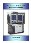
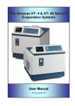
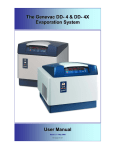
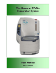
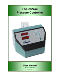
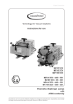
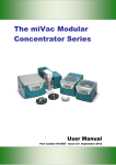
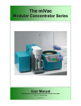
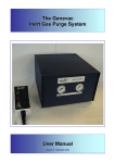
THE MIVAC SERIES QUICK START GUIDE
SETTING UP
NOTE: The system is to be positioned so that there is a 50mm air gap between each unit and
the next object; wall, fume hood etc.
EXTRACTION
SYSTEM
1.
2.
3.
4.
5.
6.
7.
8.
9.
10.
11.
12.
13.
14.
Refer to User Manual for “Safety and Maintenance Notes”.
Connect mains power lead (see diagram on reverse).
Open Lid. (For Quattro Concentrator ensure that the latch engages).
Fit rotor by carefully sliding it on to shaft.
Load the rotor with your samples; ensure that they are evenly balanced.
Close Lid. (For Quattro Concentrator lift lid to disengage latch)
Set Chamber Temperature; see below (if no temperature is selected, the unit will run at the current
chamber temperature).
Set Run Type; see below (if no type is set, the unit will use the current settings).
Set Total Run Time; see below (if no time is set, the unit will use the current settings).
Set Heat Time; see below (if no time is set, the unit will use the current settings).
Press MANUAL or AUTO button to start the run.
If the MANUAL button was pressed, the STOP button will need to be pressed to stop the run.
If the AUTO button was pressed, the run will stop after the TOTAL time has passed.
The end of run is confirmed by the system emitting 4 long beeps and unlocking the lid.
NOTE: The rotor may continue to spin slowly after the run has ended.
WHEN REMOVING YOUR SAMPLES CARE SHOULD BE TAKEN AS THE CHAMBER
AND SAMPLE HOLDERS WILL BE AT THE SAME TEMPERATURE THAT WAS SET
FOR THE RUN.
PUMP
SPEEDTRAP
CONCENTRATOR
NOTE: Ensure that the Catchpot is fitted to the lower row of vent holes on the Pump.
Follow the diagram above to connect the units together using ½” Vac hose cut to length using the hose
cutter. Both the hose and the hose cutter are available in the miVac Connection Kit – Part Number:
MCK-00000-Y00 or hoses separately, part numbers: vacuum hose: 04-4783, exhaust hose: 04-5016.
If you do not have the SpeedTrap, just connect the hose between the concentrator and the pump.
The arrows on the diagram indicate the direction of vapour flow.
Connect the interconnecting cable A (supplied in Connection Kit) between the connector on the
Concentrator and the connector on the Pump. Do not use the Mains Power Cable supplied with the
pump, this is supplied for standalone use of the pump only.
Connect Mains Power Cables B and C supplied, to the connector on the SpeedTrap and your Mains
Supply, and to the connector on the Concentrator and your Mains Supply.
NOTE: The interconnecting cable is only to be used between the Concentrator and the Pump.
OPTIMISING THE RUN SETTINGS
SPEEDTRAP
To set and adjust the required parameters use the selector knob located on the right of the control panel to
move to the desired position, the display changes with [ ] appearing at each location in turn, this means that
this is the value that will be adjusted. To adjust the value press the knob to select it, the [ ] will flash, then
turn the knob to increase or decrease the value. Once the correct value is attained, press the knob to
accept it. Repeat the procedure for all parameters. See example below:
Collection jar – fitting and removing.
NOTE: The selected value will be accepted automatically after 30 seconds if you do not press the
knob.
Once you press the knob to accept the new value, the display reverts back to displaying the
o
current chamber temperature (We have used 24 C as the current temperature for the
example).
The blue LED on the front of the SpeedTrap indicates the current condition.
Example - Setting Chamber Temperature
Select Parameter
To fit the jar, position so that the handle is to the front, lift the jar and rotate to the right a quarter turn
until resistance is felt. The collection jar is removed by rotating the jar to the left a quarter turn.
Adjust Value
After Accepting Value
NOTE: For error messages and troubleshooting refer to User Manual.
Genevac technology is protected by patents and patent applications in the USA and worldwide.
04-5058 Issue 1-4
October 2008
LED
FAST FLASH
SLOW FLASH
STEADY
CONDITION
DEFROSTING
CHILLING
CONDENSING
Genevac Limited, The Sovereign Centre, Farthing Road, Ipswich, IP1 5AP, UK Tel: +44 (0) 1473 240000 fax: +44 (0) 1473 461176
Genevac Inc, SP Industries, 815 State Route 208, Gardiner NY 12525, USA Tel: (1) 845 267 2212 Fax: (1) 845 267 2212
Email: salesinfo@genevac co.uk - Web Site: http://www.miVac.co.uk - Tech Support: [email protected]