1
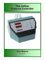
The miVac
Pressure Controller
User Manual
Issue 1 – May 2007
Part Number 04-6001
miVac Pressure Controller
Contents
GENERAL ............................................................................................................................................................2
1
Introduction ...........................................................................................................................................2
2
2.1
2.2
2.3
Safety and Maintenance Notes ............................................................................................................3
Symbols ..................................................................................................................................................3
Safety ......................................................................................................................................................3
General Information ................................................................................................................................3
3
3.1
3.2
3.3
3.4
3.5
3.6
System Description and Options ........................................................................................................3
Scope of delivery and installation ...........................................................................................................3
Checking the delivery .............................................................................................................................3
Installing the system ...............................................................................................................................4
Good procedural practice .......................................................................................................................6
Routine Checks ......................................................................................................................................6
List of acceptable solvents .....................................................................................................................6
miVac Systems and Combustible Solvents ............................................................................................6
Genevac and the ATEX Directive ...........................................................................................................6
4
4.1
4.2
4.3
4.4
4.5
4.6
4.6.1
4.6.2
4.6.3
4.6.4
4.7
Operation ...............................................................................................................................................7
Control panel ..........................................................................................................................................7
Calibration ...............................................................................................................................................7
Starting up ..............................................................................................................................................7
Operating modes of the Controller .........................................................................................................8
Selection, display of operating modes ....................................................................................................9
Setting / changing the control parameters at the controller ..................................................................10
Setting the selected control parameters ...............................................................................................10
Querying the set values ........................................................................................................................10
Changing the pressure during operation ..............................................................................................10
Set minimum pressure ..........................................................................................................................10
Venting the system ...............................................................................................................................10
TECHNICAL DATA ...........................................................................................................................................11
5
General ................................................................................................................................................11
Environment ..........................................................................................................................................11
6
EC Declaration of Conformity ...........................................................................................................12
7
Safety ...................................................................................................................................................12
8
Warranty Statement ............................................................................................................................14
9
Contact information ............................................................................................................................14
10
Disposal and Recycling .....................................................................................................................14
These instructions are subject to change without notice. No part of these instructions may be reproduced in
any form or be processed, duplicated or distributed by electronic or optical means without the written
permission of Genevac Limited. All rights reserved. © Genevac Limited.
These operating instructions should be read fully before you use the miVac system. Keep them near the
system for easy reference. Your attention is drawn in particular to Safety and Maintenance Notes.
04-6001 Issue 1 – May 2007
Page 1 of 14
miVac Pressure Controller
GENERAL
1
Introduction
Drawing on extensive experience in the drug discovery field, the miVac Series is designed to provide very high
performance coupled with ease of use, occupying the minimum of laboratory space.
The miVac Pressure Controller has been developed to improve both performance and Solvent recovery
Simple to use controls enable the control parameters to be set in an instant.
This manual will guide you through the start up requirements, set up needs and operation of the system to
facilitate the most efficient procedure to protect your product’s integrity and to ensure optimum performance at
all times.
The Operating Manual must be kept at the place of use and be available to the personnel when required.
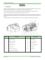
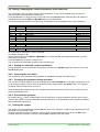
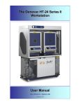
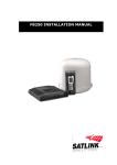
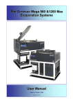
Item no.
Description
Item no.
Description
1
Controller complete
8
Ventilation valve
2
RS 232 – NOT USED
9
Inert gas connection
3
Power supply plug
10
Sensor integrated
4
Main switch Off / On
11
Check valve integrated
5
Fuse T 630 mA
12
NOT USED
6
Connection vacuum pump
13
Control valve
7
Connection vacuum apparatus
Page 2 of 14
04-6001 Issue 1 – May 2007
miVac Pressure Controller
2
Safety and Maintenance Notes
2.1
Symbols
The following safety symbols are used throughout this manual and can be found on the equipment. The
definitions and scope of each symbol is as described below.
WARNING
THIS SYMBOL INDICATES HAZARDS THAT CAN LEAD TO SERIOUS MATERIAL
DAMAGE OR POTENTIAL SERIOUS INJURY.
2.2
Safety
BEFORE OPERATING THE SYSTEM, IT IS IMPORTANT THAT THE FOLLOWING NOTES
ARE READ TO ENSURE THAT THE IMPLICATIONS TO THE SAFETY OF PERSONNEL
OPERATING THE SYSTEM AND FOR THE PROTECTION OF SAMPLE INTEGRITY ARE
UNDERSTOOD.
The Pressure Controller may only be operated under the conditions stated:
2.3
•
in the "Technical Data" section
•
on the type plate
•
in the technical specification for the order concerned
•
The Pressure Controller is used in conjunction with a vacuum pump / vacuum system in industry,
and in chemical and physical laboratories
•
The applicable regulations must be observed when it is used with hazardous substances
(corrosive, toxic, microbiological, radioactive or other hazardous substances).
General Information
When using the Pressure Controller in conjunction with miVac vacuum pumps or the miVac laboratory vacuum
systems, the instructions in the operating manuals for this equipment must also be observed.
The controller of the Pressure Controller is maintenance-free. Valves should be cleaned whenever necessary.
2.4
Limitations of use
Your miVac Pressure Controller is unsuitable for use under the following circumstances:
•
With strong acids such as HCl, TFA and HBr at all concentrations – See page 5 for approved list.
3
System Description and Options
3.1
Scope of delivery and installation
On delivery, it is advisable to unpack your system at the point of receipt, to ease the movement of the
component parts to the point of use. It would be advisable to retain the packaging as Genevac and its
Distributors will only accept returns in the original packaging.
3.2
Checking the delivery
Check the contents of the delivery as soon as possible against the delivery note and notify your Distributor
immediately of any missing or damaged parts. Refer to http://www.mivac.co.uk/contact/distributors.html for up
to date contact details.
Keep the packaging in a safe place so that it can be used when sending the controller to the manufacturer's
works or to an authorized workshop for maintenance or repair.
04-6001 Issue 1 – May 2007
Page 3 of 14
miVac Pressure Controller
3.3
Installing the system
The Pressure Controller must be installed according to the labelling attached. The relevant safety instructions
must be observed. When mounting the miVac Pressure Controller, ensure that it has a clearance of about 5 cm
from surrounding surfaces. At the same time, ensure that there is adequate ventilation.
Use pre-assembled cables supplied. Using them excludes the possibility of faulty connections. All the vacuum
lines and connections of the entire system must be checked for leaks before beginning work.
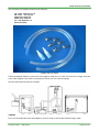
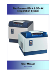
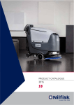
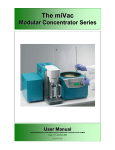
Below is an example of the Duo Concentrator, SpeedTrap and Duo Pump positioned on a bench, complete with
Pressure Controller.
Page 4 of 14
04-6001 Issue 1 – May 2007
miVac Pressure Controller
The Connection Kit supplied consists of the following:
1/2” Hose - 55mm long x 2
3/8” Hose – 1m long x 2
33mm Hose Clips x 2
25mm Hose Clips x 4
1/2”- 3/8” Reducer x 2
Electrical Cable
HOSES AND FITTINGS
Follow the diagram below to connect the units together using the 1/2” & 3/8” Vac hose cut to length using the
hose cutter supplied in the miVac Connection Kit and the 1/2”-3/8” Hose Couplings.
Secure hoses with hose clips as indicated.
CABLES
Once you have fitted the hoses and adapters, you then need to connect the electrical supply cable.
04-6001 Issue 1 – May 2007
Page 5 of 14
miVac Pressure Controller
3.4
Good procedural practice
A few general rules for safe operation of a system:
3.5
•
Ensure only users familiar with all the issues outlined in this document are permitted to operate the
equipment.
•
Do not place any objects on top of any of the system components during a run
Routine Checks:
•
Check all hose joints on a regular basis to ensure that they are secure.
•
Clean the exterior paintwork with a soft, lint free cloth using one of the following:
Detergent solution - e.g. fairy liquid
Bleach solution (if using biological agents)
Methanol
Ethanol
3.6
List of acceptable solvents
Acetic Acid
Acetonitrile (ACN)
Acetone
Ammonium Hydroxide (NH3OH)
Butan-1-ol
Butan-2-ol
Butyl Acetate
Chloroform (TCM)
1,2-Dichloroethane
Dioxane
Ethanol (EtOH)
Ethyl Acetate
Formic Acid
Heptane
Hexane (Hex)
Methanol (MeOH)
Methyl Tertiary Butyl Ether
Methylene Chloride (DCM)
Propan-1-ol or Propanol
Propan-2-ol or isopropyl
alcohol (IPA)
THF
Toluene
Water
SOLVENTS IN RED CAN ONLY BE USED IN COMPLETE SYSTEMS WHERE ALL UNITS
(CONCENTRATOR, SPEEDTRAP AND PUMP) HAVE A DATE OF APRIL 2007 OR
LATER ON THE SERIAL PLATE.
miVac Systems and Combustible Solvents:
Please note it remains the responsibility of the user to consider safety when evaporating any combustible
solvents and ensure the system is placed in a well ventilated environment.
Genevac and the ATEX Directive:
This Statement is applicable only to Member Countries of the EU.
Please note that it remains the responsibility of the user to consider any solvents being evaporated within the
context of the ATEX directive. The presence of solvents on the list above indicates only that they will not
damage the system. If further information is required, please contact your Sales Representative or visit
http://www.miVac.co.uk
Page 6 of 14
04-6001 Issue 1 – May 2007
miVac Pressure Controller
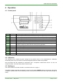
4 Operation
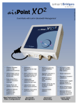
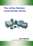
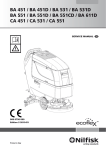
4.1 Control panel
1
2
3
4
5
6
7
VALUE:
STATE:
mbar:
Torr:
psi:
UP:
OK:
VALUE: 4 digit 7 segment LED display – Pressure value, parameter value
4 digit 7 segment LED display – Mode, operating mode, type of parameter
Luminous spot = identification of the unit of measurement mbar (factory setting)
Luminous spot = identification of the unit of measurement Torr
Luminous spot = identification of the unit of measurement psi
arrow key changes values upwards
setting level – selection of the parameters to be set – activation of the setting values
Transfer of temporary values into the memory during operation.
8
9
10
11
12
13
DOWN:
START:
AIR:
STOP:
P min
ON/OFF
arrow key changes values downwards
activation of a procedure
Venting – while button is pressed
end of a procedure
Reduction of the pressure to a minimum
ON/OFF Switch
4.2 Calibration
The calibration menu enables long-term changes in the pressure sensor to be compensated for. Calibration
should take place every six months or whenever displayed pressures cease to be plausible.
We recommend that the calibration be performed with a comparison measurement device. For this, the
measured values: normal and low pressure must be input.
4.3 Starting up
The miVac Pressure Controller should be connected as shown on page 4.
The MiVac Pressure Controller is switched on by the rocker switch POWER located on the device. The device
is ready for operation after a short initializing routine, during which a beep sounds and all light elements light up
briefly.
04-6001 Issue 1 – May 2007
Page 7 of 14
miVac Pressure Controller
4.4 Operating modes of the Controller
Mode 1
Manual mode
Lowering the working pressure until the set pressure has been attained and held constant.
After switching on the power supply to the vacuum pump and controller, and selecting mode 1, the
process is started by pressing the start button. The pressure is reduced to the set pressure value
Ps (mbar)*, see Setting Control Parameters. The hysteresis value PH (mbar), which has to be
previously set, determines the pressure increase after which the pressure is reduced again.
In this way, the pressure is held constant by two defined threshold values (set value, hysteresis).
This control procedure is repeated until the operator terminates operation (STOP key). The
concentrator may be ventilated by pressing the AIR key.
The set value may also be changed during operation in manual mode by means of (↑,↓). This set
value is not stored, so the set value present at program start is retained. (see chapter 6.3.5)
"ecoflex" pump models work directly at the set pressure value. It is not necessary to set the
hysteresis PH.
Mode 2
Manual mode with settable pressure reduction – see opposite
As in operating mode 1, but with an additional function for adapting the vacuum for
processes in which the boiling point shifts (reduction of the concentration of the volatile
component).
Reduces the risk of bumping by reducing the pressure slowly to the required final value.
After attaining the set pressure value Ps, there is a further pressure reduction corresponding to
the set pressure value PL (1...1000 mbar) and a time tL (1...240 min)** which has to be defined
previously. The maximum rate of change of pressure is limited to 1 mbar/s.
Mode 5
Automatic operation – see opposite
Lowering the working pressure until a boiling point is found automatically (also with
mixtures).
In the automatic operating modes, the controller continuously checks the course of the pumping
out curve (pressure change per unit time). It interprets significant deviations in the slope as the
start of vapour formation and defines this pressure point as a set value. That is, the controller
treats the value found in this way from now on in the same way as the set value in the previous
modes. The sensitivity of the controller can be set with parameter PA (a higher PA value for
volatile substances and a lower PA value for non-volatile substances. See Setting Control
Parameters.
After finding the pressure point Ps, the controller carries on working in mode 1.
In the case of certain solvent mixtures or deeply cooled condensates, the optimal boiling point is
not always found. In such cases, the distillation process may be further optimised by repeating
with changed PA values. Maximum distillation speed can be achieved in this way, taking into
account the cooler capacity and the stability of the vaporization process (no frothing of the
distillate).
Genevac recommends starting with a PA value of 10 for a Quattro Concentrator and a PA value
of 40 for a Duo Concentrator.
Mode 6
*
**
Automatic operation with settable pressure reduction – see opposite
As operating mode 5, and after the boiling point has been found, causes a further lowering
of the working pressure corresponding to the set pressure value PL (mbar) and tL (min)** .
Corresponds to the set unit of measurement: mbar, Torr, psi
tL is displayed on the control panel in minutes
Page 8 of 14
04-6001 Issue 1 – May 2007
miVac Pressure Controller
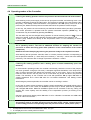
Mode 2 – Example of pressure control
Example: If Ps = 30 and Pl = 10 then the Final Pressure = 20
Modes 5 and 6 – Discussion
Mode 5 allows the controller to spot the onset of boiling and sets Ps accordingly. If this mode is used then
solvent recovery will be maximised but at the expense of speed.
Probably a better method to use is Mode 6 where you can specify the further reduction in pressure PL after the
controller determines boiling point. Dropping the pressure below boiling point by PL will cause the solvent to
cool and increase the evaporation rate.
Some experimentation will be required in order to determine the optimum settings for your particular
application. We have provided a “Notes” page at the back of this manual for this reason.
4.5 Selection, display of operating modes
After switching on, the desired operating mode can be set with the cursor keys ↑ UP and ↓ DOWN.
The current operating mode appears in the first position of the display and is activated with the START key (a "" appears in the second position of the display).
The STOP key terminates the operating mode ("-" disappears) and the control is thus disabled.
The current control parameters can be brought into the display while the program is running without interrupting
the control sequence by pressing the START key for 3 seconds.
The code letter of the currently selected parameter appears in the STATE display field and its associated value
in the VALUE display field.
04-6001 Issue 1 – May 2007
Page 9 of 14
miVac Pressure Controller
4.6 Setting / changing the control parameters at the controller
The configuration menu is used to set the control parameters. It may only be entered when the control is
inactive (control interrupted with the STOP key).
Press the OK button for three seconds. The mode code in the VALUE display field changes to P. Select the
setting parameter with the ↑ UP and ↓ DOWN buttons (see table below).
Only those parameters which have to be set for the selected mode are displayed. Key to the code letters:
C
CH
CL
P
PS
PH
PL
PA
t
tL
tH
F
FA
Pressure sensor calibration
<de>
at normal pressure (High)
<de>
at low pressure (Low) (at lowest possible pressure, e.g. 10 mbar)
Pressure settings in (<de> = set pressure unit mbar, torr or psi)
<de>
Set value
<de>
Hysteresis
<de>
Amount of pressure reduction (Low pressure)
<de>/min threshold value for detecting the boiling point automatic mode
Time setting
min
Time for the pressure reduction (Low pressure)
min
NO FUNCTION
Frequency reduction in %, starting from the maximum operating frequency
%
INFO ONLY – NOT APPLICABLE
Set this last
Set this first
Modes 1, 2,
Modes 1, 2, 5, 6
Modes 2, 6
Modes 5, 6
Modes 2, 6
Modes 1, 2, 5, 6
Modes 5, 6
After selecting the parameter, confirm it with OK.
This display changes to "E".
Set the desired value with the↑ UP and↓ DOWN keys, confirm with OK, and repeat with the other required
parameters if necessary.
Press the STOP key to leave the setting menu.
The set values are stored after the setting menu has been left.
4.6.1 Setting the selected control parameters
During operation, the current pressure value (mbar) is shown in the VALUE display field, there is a "P" in the
STATE display field.
4.6.2 Querying the set values
The set values can be displayed during operation by repeatedly pressing the START button.
4.6.3 Changing the pressure during operation
The set value can be changed at any time by pressing the UP and DOWN keys. The display changes from "P"
to "S" during the setting. This set value is temporarily active. After pressing the "STOP" button, the originally
stored set value becomes active once more.
If this iteratively determined set value is to be permanently transferred into the memory, this may be done by
pressing the OK key once.
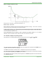
4.6.4 Set minimum pressure
By pressing the Pmin button, the diaphragm pump is switched to continuous operation and the vacuum valve
remains open until the minimum attainable pressure is achieved . The attainable minimum pressure stabilizes
after an adequate waiting time.
4.7 Venting the system
The system may be vented by pressing the AIR key at any time. However, it must be noted that this also ends
the search run in automatic mode.
Venting is intermittent while the controller is active. That is venting takes place only as long as AIR is kept
pressed. When the controller is inactive, pressing AIR completely vents the system.
Page 10 of 14
04-6001 Issue 1 – May 2007
miVac Pressure Controller
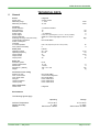
TECHNICAL DATA
5
General
Sensor
Sensor type
Measuring range
Measuring uncertainty
Controller
Sensor interface
Scan frequency
Resolution ADC
Power supply
Sensor signal
Pressure indicator
Switching accuracy/ control accuracy
Communication interfaces
Power consumption
Controller
in normal operation
Fuse (internal controller)
integrated
ceramic sensor
1 - 1100
±2; FS
mbar
mbar
3 conductor interface
10
12
+ 5 stabilized
0.5 to 4.5 (optionally also 0..5 V or 4..20 mA possible)
digital; red, 9 mm high digits in mbar, torr or psi
±1
NOT AVAILABLE
max. 20 (depends upon the control power)
5
Power pack
Operating voltage
Operating frequency
Output voltage
Output current
Output power
internal
90 .. 264
50 / 60
24
1.25
30
Entire unit
Protective system
Working temperature
Device fuse
Dimensions (W/D/H)
Weight
IP 20
15 - 40
T 0.630
195 / 178 / 105
1.6
Connectors on the casing
IN/OUT: RS 232
OUT: Control valve
OUT: Water valve
inert gas
vacuum apparatus
vacuum pump
NOT AVAILABLE
Control valve integrated
NOT AVAILABLE
Hose nozzle DN 4
Hose nozzle DN 8
Hose nozzle DN 8
Other components
Check valve
integrated
Hz
Bit
V
V
digit
W
A
V AC
Hz
V DC
A
W
°C
A
mm
kg
Environment:
The following figures apply:
Ambient Temperature:
Relative Humidity:
Altitude:
04-6001 Issue 1 – May 2007
Operating
Storage
0°C to 30°C
0 – 95%
Sea Level to 1,600m
5°C to 40°C
0 – 90%
Sea Level to 12,000m
Page 11 of 14
miVac Pressure Controller
6
EC Declaration of Conformity
The miVac Pressure Controller conform to the following directives:
73/23/EU
Low Voltage Directive
98/37/EU
Machinery Directive
89/336/EU
Electromagnetic Compatibility Directive
The miVac Pressure Controller fulfils the following product standards:
BS EN 61010-1
BS EN 60204-1
BS EN 50110-1 (DIN VDE 0105-100)
BS EN 292-1 and 292-2
Safety requirements for electrical equipment for measurement, control,
or laboratory use.
Electrical equipment of machines
Operation of electrical installations
Safety of machines, devices and plants
The CE sign is located on the rating plate.
When fitting the controller into a system (vacuum apparatus), it must be ensured that the system conforms
to these directives before starting it up.
Observe the binding national, local and plant-specific regulations.
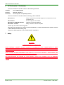
7
Safety
WARNING!
THIS SYSTEM MUST BE EARTHED
THIS SYSTEM IS A SAFETY CLASS 1 PRODUCT ACCORDING TO IEC CLASSIFICATION. IT MUST
NEVER BE USED WITH ANY INTERRUPTION TO THE SAFETY EARTH CONDUCTOR. IT IS AN
INSTALLATION CATEGORY II PRODUCT AND IS INTENDED TO OPERATE FROM A NORMAL SINGLEPHASE SUPPLY.
THIS SYSTEM HAS BEEN DESIGNED TO BE USED IN A POLLUTION DEGREE 1 ENVIRONMENT (NO
POLLUTION, OR ONLY DRY NON-CONDUCTIVE POLLUTION).
ANY MAINTENANCE OR REPAIR OF THIS PRODUCT SHALL BE CARRIED OUT BY GENEVAC
PERSONNEL (OR APPROVED REPRESENTATIVES OF GENEVAC) USING ONLY APPROVED SPARE
PARTS.
Page 12 of 14
04-6001 Issue 1 – May 2007
miVac Pressure Controller
NOTES
04-6001 Issue 1 – May 2007
Page 13 of 14
miVac Pressure Controller
8
Genevac Limited
The Sovereign Centre
Farthing Road
Ipswich
IP1 5AP
United Kingdom
Sales and Service Hotlines
This product is guaranteed for period of 12
months from the date of delivery to site. In the
unlikely event of any defect arising due to faulty
materials or construction resulting in system
failure, the unit will be repaired free of charge.
This to include all labour and component costs
incurred.
This warranty is subject to the following
provisions:
1.
System must be sited, installed and
operated in accordance with User Manual.
2.
Unit only used for the purpose it was sold,
and in accordance with Genevac published
compatible solvent list.
3.
Regular
cleaning
and
preventative
maintenance schedule to be adhered to as
detailed in User Manual. See item 3.5
Routine Checks on Page 6.
4.
Warranty does not cover accidental damage,
misuse, modifications or inappropriate repair
by untrained personnel.
5.
Warranty does not cover consumable items.
Service Hotline: +44 (0) 1473 243000
Sales Hotline: +44 (0) 1473 240000
Fax: +44 (0) 1473 461176
Email: [email protected]
Web site: www.miVac.co.uk
___________________________________
Genevac Inc
707 Executive Boulevard
Suite D
Valley Cottage
New York
10989
United States of America
Sales and Service Hotline
Warranty Statement
Failure to adhere to the above would invalidate
the warranty and result in the costs of repairs
being charged.
9
Contact information
See opposite; please ensure that you have the
serial numbers at hand for the components of
your system.
10 Disposal and Recycling
(1) 845 267 2211
Fax (1) 845 267 2212
Email: [email protected]
___________________________________
For main Distributor listing, visit:
www.mivac.co.uk/contact/distributors.html
Page 14 of 14
The miVac product should not be discarded in
your regular disposal stream. Contact your
Distributor or Genevac for proper disposal
instructions.
Within the EU, it is Genevac’s responsibility
under the WEEE directive to provide for the
recycling of their products.
04-6001 Issue 1 – May 2007