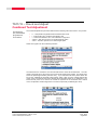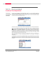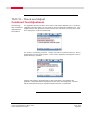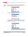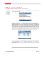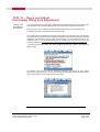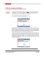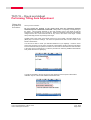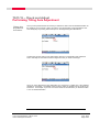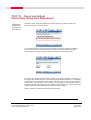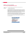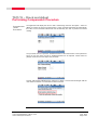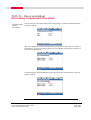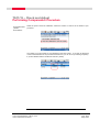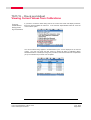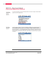
1
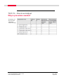
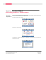
Viva TPS
October 2010
TS11/15 Total Stations
Check and Adjust Procedure
Summary
Leica builds total stations to the highest quality and calibrates each instrument before it leaves
the Factory. After the instrument is shipped or used in the field under changing temperature
conditions, the instrument will physically change. In order to provide the customer with the
ability to field calibrate every total station, Leica offers the Check and Adjust routine on the
TS11/15 instruments. This guide will explain why the Check and Adjust is needed and how to
perform the procedure. This procedure will allow the user to assure that the instrument is
providing measurements to standards.
© 2010 Leica Geosystems Inc. – All rights reserved
TS11/15 – Check and Adjust
Why is procedure needed?
Why is the
procedure
needed?
Leica instruments are manufactured, assembled and adjusted to the best possible quality.
Quick temperature changes, shock or stress can cause deviations and influence the instrument
accuracy. The physical relationship of the axis of the instrument are physically different, if the
operating temperature of the instrument is 32° F (0° C) versus 95° F (35° C). Materials contract
and expand. Survey instruments are also exposed to shocks and stress during transportation to
the project site and on the project site. These stresses will also change the relationship of the
instrument components.
Please refer to Leica TS11/TS15 User Manual, Pages 74 – 88 and the Leica Viva Series
Technical Reference Manual version 3 Pages 622 - 647
When should
you perform
procedure?
Leica recommends that the Check and Adjust Routine is performed for the following situations:
•
•
•
•
•
•
What
adjustments
are
determined
by
procedure?
Before the first use after the instrument has been shipped by any courier service
Before every high precision survey (for example.. high precision traverse)
After any rough or long transportations to a job site
After a long period of storage of the instrument
After a long period of use of the instrument (a reminder can be set on the instrument
for different periods of time)
When the change in temperature of the working environment is more than 36° F (20°
C) between the working temperature of the last calibration and the current working
temperature. In other words if the working environment temperature changes by 36° F
(20° C) since the last calibration you need to perform the Check and Adjust routine
The following instrument errors can be determined electronically by the Check and
Adjust procedure:
•
•
•
•
•
•
l, t - longitudinal and transversal index errors of compensator i - Vertical index error, related to the standing axis
c Hz - Collimation error, also called line of sight error
ATR Hz - ATR zero point error for horizontal angle option (if instrument is equipment
with ATR)
ATR V - ATR zero point error for vertical angle option(if instrument is equipment with
ATR)
a - Tilting axis error – This check must be done separate from all other procedures
The results from check and adjust are displayed as errors but used with the opposite sign as
corrections when applied to measurements.
There is a combined procedure that will determine the values for l,t,I,c Hz and ATR zero point.
You can also perform a test for the compensator errors alone if needed. The tilting axis (a)
check must be done as a completely separate test.
Please refer to Leica Viva Series Technical Reference Manual version 3 Pages 622 - 647
for detailed explanation and diagrams of axis relationships
TS11/15 Total Stations FW Ver. 3.00
Check and Adjust Procedure
OCT, 2010
Page 2/22
Continued on Next Page
TS11/15 – Check and Adjust
Why is procedure needed?
Summary of
Errors to be
adjusted
electronically
TS11/15 Total Stations FW Ver. 3.00
Check and Adjust Procedure
OCT, 2010
Page 3/22
TS11/15 – Check and Adjust
Preparation and Field Requirements
Prepare the
instrument
and target
The procedure for performing the Check and Adjust procedure is very simple. You need to let
the instrument acclimate to the surrounding temperature, have a good solid setup that will not
be disturbed during the procedure and you need to have the instrument setup in a place where
it will not be exposed to direct sunlight during the procedure. One of the most important things
that the operator needs to do is to remember to manually point at the target when prompted by
the routine on the TS. The needed preparation and field requirements in detail are as follows:
1.
First get the instrument acclimated to the current working environment temperature.
This needs to be started first and then can continue while you are performing other
steps in the preparation. When you arrive at the place where the instrument will be
setup to perform the procedure, open up the instrument case to expose the instrument
to direct contact with the working environment. If you are taking the instrument out of
a building or out of a vehicle that has a different temperature other than the one of the
working environment you will need to wait until the instrument has become acclimated
to the ambient air temperature of the work site. The rule of thumb or this is to wait 2
minutes per every 2° F or per 1° C of difference in the temperature of the place where
the instrument originated and the ambient air temperature of the work site.
2.
Setup the instrument in a very stable place that will not be effect by vibrations or other
disturbances during the procedure
3.
The instrument needs to be setup in a place that is protected from direct sunlight in
order to avoid one side of the instrument being heated more than the opposite side of
the instrument. The best conditions can be found usually early in the morning and with
overcast sky. Setting the instrument up under a tree for shaded area or on a shaded
side of a building are good, common locations that can be used.
4.
If you are also performing the test for ATR adjustments you will need to set up a Leica
circular prism approximately 330 ft (100 m) away from the instrument. You can setup
the prism being used as the target for the testing in direct sunlight. Setup up the prism
within +/- 9° of the horizontal plane of the instrument you need to use a Leica circular
prism. Do not use a 360° prism for this procedure.
Note: If you are not performing the procedure for ATR you do not need to use a prism for the
procedure.
The combined test procedure, the titling axis procedure, and compensator only test will be
explained
TS11/15 Total Stations FW Ver. 3.00
Check and Adjust Procedure
OCT, 2010
Page 4/22
TS11/15 – Check and Adjust
Performing Combined Test Procedure
Accessing
Check and
Adjust Wizard
After you have prepared the instrument as explained in the Preparation and Field Requirements
section you can follow the Check and Adjust Wizard.
From the main menu select 4 User
Next, select 5 Check & Adjust
You will then be reminded to make sure the instrument is acclimatized to the surroundings and
shaded from direct sun.
TS11/15 Total Stations FW Ver. 3.00
Check and Adjust Procedure
OCT, 2010
Page 5/22
Continued on Next Page
TS11/15 – Check and Adjust
Combined Test Adjustment
Performing
the Combined
Adjustment
Procedure
The combined adjustment procedure determines the following instrument errors in one process:
•
•
•
•
•
l, t - Compensator longitudinal and transversal index errors
i - Vertical index error, related to the standing axis
c - Horizontal collimation error, also called line of sight error
ATR Hz - ATR zero point error for horizontal angle option
ATR V - ATR zero point error for vertical angle option
Select the top option for the combined procedure
The Wizard will now remind the user what should be done at the first measurement. The user
needs to manually aim at the center of the Leica Round Prism being sighted. The target prism
should be placed approximately 330 feet away. If you instrument has ATR, please check the
box for the “Calibrate the automatic target aiming” option. After you have carefully sighted the
center of the Leica Round Prism both vertically and horizontally select the F1 (Meas) key. The
instrument will pause for a moment as it reads its systems for the horizontal circle, vertical
circle, compensator and the image seen in the ATR components (if calibrating the ATR)
TS11/15 Total Stations FW Ver. 3.00
Check and Adjust Procedure
OCT, 2010
Page 6/22
Continued on Next Page
TS11/15 – Check and Adjust
Combined Test Adjustment
Performing
the Combined
Adjustment
Procedure
You have now completed the first measurement in FACE 1. If it is a motorized model, the
instrument will automatically turn to FACE 2 to the target. If the instrument is not motorized the
user will be required to manually point at the target in FACE 2. Once the instrument has turn
into FACE 2 you will see the following screen:
At this point in the procedure the user needs to manually point to the center of the target prism.
Note: Do not accept the pointing to the target prism that the instrument performs
automatically if the instrument is motorized. Always make a completely manual pointing to
the target prism. This procedure depends on the user manually point to the target so that the
instrument can calculate the error corrections. When the motorized instruments automatically
change face the aim of the instrument will be very close to the center of the target. Please
always manually perform the pointing to the target.
After you point the instrument to the center of the target prism select the F1 (Meas) key to
record the readings. You have now performed the first of a set of FACE 1 and FACE 2
observations.
The application will now report the standard deviations of the measurements you have taken.
At this time you only have one measured set and the application cannot report these values
until multiple sets are measured. The user now needs to continue measuring sets by selecting
F1 (Next).
TS11/15 Total Stations FW Ver. 3.00
Check and Adjust Procedure
OCT, 2010
Page 7/22
Continued on Next Page
TS11/15 – Check and Adjust
Combined Test Adjustment
Performing
the Combined
Adjustment
Procedure
The application will then prompt the user to either “Add another calibration loop” or “Finish the
calibration & store the results”. The user needs to choose to add another calibration loop. Leica
suggests that the user repeats the process until they have a minimum of three (3) sets. Select
the F1 (Next) key to continue measurements
The process of measuring continues. Please note that the instrument starts the second
measurement set in the FACE 2 position. This is how the application was designed in order to
provide efficiency in operation.
Continue with pointing to the target prism in FACE 2 and FACE 1 as prompted by the
application. Please remember to manually point at the center of the target prism. Continue
with the measurements until you complete a FACE 2 and FACE 1 measurement.
Continued on Next Page
TS11/15 Total Stations FW Ver. 3.00
Check and Adjust Procedure
OCT, 2010
Page 8/22
Performing
the Combined
Adjustment
Procedure
Once you complete the second calibration loop the system can now start to report the standard
deviations. These values tell the user how closely they are pointing at the same spot on the
target as the calibration loops progress. Do not expect these values to be reported as 0°00’00”.
Your measurements will have error and that is why you repeat the steps.
Select F1 (Next) and then choose to “Add another calibration loop” to perform the last of the
recommended of 3 loops of the process.
Once you have completed the F1 and FACE 2 of the measurements you will again view the
standard deviations of the now.. all three… of the calibration loops. If the values are
acceptable, select the F1 (Next) key. Acceptable values would be within the resolution of the
model of the instrument. For example, if you have a 3 second model of the instrument you
should be within 3” to 6” in standard deviation.
Continued on Next Page
TS11/15 Total Stations FW Ver. 3.00
Check and Adjust Procedure
OCT, 2010
Page 9/22
TS11/15 – Check and Adjust
Combined Test Adjustment Procedure
Calibration
Results for
Combined
Adjustment
Procedure
This time when prompted to add more calibration loops or finish the process, choose “Finish the
calibration & store the results”
You will now view the results of the Check & Adjust procedure you just performed. It may be
helpful to view the old correction values and the new correction values you have just
determined in the same view. To do this, select the F5 (More) key until the middle column is
displaying the values from the previous procedure under the Old column. You should notice
some changes between the values. The amount change between the Old and New values
depend on the change in the condition. For example, if you only performed this procedure
every 6 months and the difference in temperature between these times is say 70º F there might
be a large difference. If you follow the recommended procedures carefully for the instrument
setup, manually aim at the target prism carefully each time, and observe that the standard
deviation in your points are within the angular resolutions of the model of instrument you are
using, you can accept the values from your procedure by selecting the F1 (Finish) button.
Continue out of the Check & Adjust Wizard and you now ready to perform measurements with
you TS instrument which is now automatically applying these new corrections to
measurements. You now only need to perform the Tilting Axis Adjustment (a) to have a fully
calibrated instrument.
TS11/15 Total Stations FW Ver. 3.00
Check and Adjust Procedure
OCT, 2010
Page 10/22
TS11/15 – Check and Adjust
Performing Tilting Axis Adjustment
Tilting Axis
Adjustment
Procedure
You will now perform the Tilting Axis (a) adjustment the tilting axis error (a) is caused by the
change between the mechanical tilting axis and the line perpendicular to the vertical axis.
Please refer to Leica Viva Series Technical Reference Manual version 3 Pages 622 - 647
for detailed explanation and diagrams of axis relationships
The requirements for acclimating the instrument and keeping the instrument from direct sunlight
are still the same as required by the Combined Adjustment. Most users perform the Combined
Adjustment and then follow with the Tilting Axis procedure. To avoid influences from the Hz
collimation error (c) you should determined prior to the tilting axis error which is done in the
Combined Adjustment. You do not need a prism target to perform the Tilting Axis adjustment.
To access this procedure select the “Check & adjust the tilting axis” option in the Check and
Adjust Wizard
The Wizard will remind you that the Horizontal Collimation test should be done before
performing this Titling Axis test. If you have completed and accepted the combined test, select
the F4 (OK) function key and continue into the procedure.
Continued on Next Page
TS11/15 Total Stations FW Ver. 3.00
Check and Adjust Procedure
OCT, 2010
Page 11/22
TS11/15 – Check and Adjust
Performing Tilting Axis Adjustment
Tilting Axis
Adjustment
Procedure
To perform the measurements for the titling axis you do not need a prism as the target. The
instrument will not be measuring any distances or ATR images. You only need a target that is
at a very steep sight. You can sight a target that is high above the horizontal plane of the
instrument or very low below the horizontal plane. The ranges are:
High – Target must be in the range of a zenith angle = 63° - 27°
Low – Target must be in the range of a zenith angle = 117° - 153°
This target could be something like a corner of a tall building or corner of a window frame on a
building if sighting a steep zenith angle. The user just needs to find a target that can be
identified and sighted (only requires an optical sight) repetitively. The user needs a target that
falls with the angular ranges that is clear enough to identify the same spot when sighting in
FACE 1 and FACE 2 during the procedure. It is also helpful to remove the instrument carrying
handle before trying to sight with the peep sights on the telescope housing.
At this point in the procedure the user needs to manually point to the center of the target. After
pointing to the center of the target prism select the F1 (Meas) key to record the reading. The
instrument will pause for a moment while internal readings are being recorded. You have now
completed the first measurement in FACE 1. If it is a motorized model, the instrument will
automatically turn to FACE 2 to the target. If the instrument is not motorized the user will be
required to manually point at the target in FACE 2. Once the instrument has turn into FACE 2
you will see the following screen:
Continued on Next Page
TS11/15 Total Stations FW Ver. 3.00
Check and Adjust Procedure
OCT, 2010
Page 12/22
TS11/15 – Check and Adjust
Performing Tilting Axis Adjustment
Tilting Axis
Adjustment
Procedure
Once you are in FACE 2…
Do not accept the pointing to the target prism that the instrument performs
automatically if the instrument is motorized. Always make a completely manual pointing to
the target. This procedure depends on the user manually point to the target so that the
instrument can calculate the error corrections. When the motorized instruments automatically
change face the aim of the instrument will be very close to the center of the target. Please
always manually perform the pointing to the target.
Carefully point to the center of the target now that you are in FACE 2 and then select the F1
(Meas) key to record the readings. You have now performed the first of a set of FACE 1 and
FACE 2 observations.
You will now be able to review your standard deviations of your sightings. However, at this
point in the procedure you only have a single set of observations and this cannot be calculated.
Leica recommends that you perform a minimum of three sets of observations for this test which
is the same as the combined test. To start the procedure of observing additional observations
sets, please select the F1 (Next) key.
You will be navigated to the next screen and here please choose the option “Add another
calibration loop” to continue with additional observation sets.
Continued on Next Page
TS11/15 Total Stations FW Ver. 3.00
Check and Adjust Procedure
OCT, 2010
Page 13/22
TS11/15 – Check and Adjust
Performing Tilting Axis Adjustment
Tilting Axis
Adjustment
Procedure
Once you have performed the second set you will then be able to see the standard deviation for
the sightings you have made. Again, this value is only representing a value that tells the user
how closely they are pointing to the same spot on the target during the observations.
Continue the process until you have performed a minimum of 3 observation sets. Please be
sure to manually aim the instrument at the target each time you observe the target.
Once you have observed the last observation set, choose the F3 (Next) key if the standard
deviation is acceptable. Acceptable values would be within the resolution of the model of the
instrument. For example, if you have a 3 second model of the instrument you should be within
3” to 6” in standard deviation.
Continued on Next Page
TS11/15 Total Stations FW Ver. 3.00
Check and Adjust Procedure
OCT, 2010
Page 14/22
TS11/15 – Check and Adjust
Performing Tilting Axis Adjustment
Calibration
Results for
Titling Axis
Procedure
Choose the option “Finish the calibration & store the results” to accept the results of the
procedure and have a chance to review
The next page shows the old correction value and the new correction value for comparison.
The user can choose to accept the results by choosing F1 (Finish) or observe the entire
procedure again and throw out all the current observations by selecting F2 (Redo)
If you follow the recommended procedures carefully for the instrument setup, manually aim at
the target prism carefully each time, and observe that the standard deviation in your sightings
are within the angular resolutions of the model of instrument you are using., please accept the
values shown. You should see some change in the old versus the new and the amount of
change will depend on the difference in the conditions the instrument was working in when the
previous check and adjust was performed versus the current conditions.
Select F1 (Finish) to accept the final results of the procedure.
Continued on Next Page
TS11/15 Total Stations FW Ver. 3.00
Check and Adjust Procedure
OCT, 2010
Page 15/22
TS11/15 – Check and Adjust
Performing Compensator Procedure
Compensator
l and t
Procedure
The compensator adjustment procedure determines the following instrument errors:
l - Compensator longitudinal index error
t - Compensator transversal index error
These are also determined in the Combined Procedure explained earlier. If the user desires to
determine these values for each setup he can perform the compensator procedure. The
compensator index errors occur if the vertical axis of the instrument and the plumb line are
parallel, but the zero points of the compensator and the circular level do not coincide. The
calibration procedure electronically adjusts the zero point of the compensator. The plane of the
dual axis compensator of the TPS1200 is defined by a longitudinal component in the direction
of the telescope and a transversal component perpendicular to the telescope.
The requirements for acclimating the instrument and keeping the instrument from direct sunlight
are still the same as required by the Combined Adjustment. This procedure requires no target.
Motorized version of the TS instruments will automatically turn the instrument after measuring
but non-motorized version will need to be manually orientated between measurements
To access this procedure please choose the “Check & adjust the compensator” option in the
Check and Adjust Wizard
Continued on Next Page
TS11/15 Total Stations FW Ver. 3.00
Check and Adjust Procedure
OCT, 2010
Page 16/22
TS11/15 – Check and Adjust
Performing Compensator Procedure
Compensator
l and t
Procedure
The application will display the current l and t values being read from the system. Select F1
(Meas) to continue to the Face 2 measurement. Again, motorized instrument will automatically
turn 180° but non-motorized instruments must be manually turn 180° to perform the second
reading
The procedure will now report the standard deviation of the measurement s sets performed.
Since you now only have one set no standard deviation can be reported. Please select F1
(Next) to continue to the next step in the procedure.
Choose “Add another calibration loop” and then F1 (Next). Leica recommends again that the
user makes a minimum of 3 measurement sets for this test.
Continued on Next Page
TS11/15 Total Stations FW Ver. 3.00
Check and Adjust Procedure
OCT, 2010
Page 17/22
TS11/15 – Check and Adjust
Performing Compensator Procedure
Compensator
l and t
Procedure
You will again enter the measurement mode of the procedure. Repeat the measurements by
selecting F1 (Meas).
After you complete the second measurement loop you will get the screen with the number of
measurement = 2 and will now need to repeat one more calibration loop to gain the minimum of
three sets of measurements.
You will finally get to the third calibration loop and will have 3 sets of measurements. Select F1
(Next) to continue.
Continued on Next Page
TS11/15 Total Stations FW Ver. 3.00
Check and Adjust Procedure
OCT, 2010
Page 18/22
TS11/15 – Check and Adjust
Performing Compensator Procedure
Compensator
l and t
Procedure
Select the option “Finish the calibration & store the results” to continue to the results of your
procedure.
The results of your procedure are now displayed in the New column. If you wish to discard all
of the measurements from the procedure and start over you can do so by selecting F2 (Redo).
If you are satisfied with the results then select F1 (Finish).
TS11/15 Total Stations FW Ver. 3.00
Check and Adjust Procedure
OCT, 2010
Page 19/22
TS11/15 – Check and Adjust
Viewing Current Values from Calibrations
Current
Calibrations
being used
by Instrument
If you wish to review the values being used in the TS from the Check and Adjust procedures,
these are always available for reference. In the Check & Adjust Wizard select the “View the
current values” option.
The current values being applied to measurements by the TS are displayed in the Current
column. The user can toggle the right column to display the Date of Calibration (Date),
Standard Deviation of Value (Accuracy) from procedure, and Internal Instrument Temperature
(Int T) recorded at time procedure was completed.
TS11/15 Total Stations FW Ver. 3.00
Check and Adjust Procedure
OCT, 2010
Page 20/22
TS11/15 – Check and Adjust
Check and Adjust User Options
Configure
Check and
Adjust
Options
To set the user options for the Check & Adjust Wizard, choose the “Configure Check & Adjust”
option from the main Wizard menu.
Set User
Reminder
Interval
The user needs to choose the interval of time that he would like to be reminded to perform the
Check and Adjust procedure. If one or more adjustment values date values are older than
the time specified with this parameter, then a reminder message is displayed each time the
instrument is turned on. Leica recommends that this is done at least once a month and also for
the list of situations such as immediately after the instrument has been shipped via a courier
service as listed at the beginning of this guide. After making your selection choose F1 (Finish)
to continue.
TS11/15 Total Stations FW Ver. 3.00
Check and Adjust Procedure
OCT, 2010
Page 21/22
TS11/15 – Check and Adjust
Performing Compensator Procedure
Create a
Report Sheet
The next option is one that can be used to create a ASCII file containing a report for the
information from the Check and Adjust routine. If selected the user must give the name of the
file to be created in the Report Sheet: field and will also need to specify the format file that will
be used to generate the report in the Format file to use: field. The ASCII file created will
appear in the \Data directory on the internal memory of the TS. The format file can be created
by using the Format Manager application in the Leica Geo Office software suite. The format file
must be transferred to the internal memory of the TS in order to be utilized by this routine.
If you have questions or comments about the information in this guide, please contact Leica
Technical Support at:
Toll Free: 1-800-327-4773
Email: [email protected]
You can also find more information on Leica MyWorld at:
https://myworld.leica-geosystems.com
TS11/15 Total Stations FW Ver. 3.00
Check and Adjust Procedure
OCT, 2010
Page 22/22