1
3DQDVRQLF7HOHSKRQH6\VWHPV
Panasonic .;7$
www.voicesonic.com
Phone: 877-289-2829
Advanced Hybrid System
Installation Manual
Panasonic KX-TA624, KXTA624, TA624, KX-TA62460, KX-TA62470, KX-TA62477, KX-TA62491, KX-TA62493
Model No.
Please read this manual before connecting the Advanced Hybrid System.
KX-TA624
Thank you for purchasing this Panasonic Model KX-TA624,
Advanced Hybrid System.
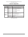
System Components
Model
Description
Service Unit
KX-TA624
Advanced Hybrid System (Main Unit)
Telephone
KX-T7135
KX-T7130
KX-T7020
KX-T7030
KX-T7050
KX-T7055
Proprietary telephone with backlit display
Proprietary telephone with display
Proprietary telephone
Proprietary telephone with display
Proprietary telephone
Proprietary telephone
KX-TA62460
KX-TA62470
KX-TA62477
KX-TA62491
KX-TA62493
Doorphone/Door Opener Card
8 Extension Expansion Card
3 CO Line and 8 EXT Expansion Card
OGM/FAX Detection Card
Caller ID Card
KX-T30865
Doorphone
Optional
Equipment
System Components Table
2
Attention
• Keep the unit away from heating appliances and electrical noise generating devices such as
fluorescent lamps, motors and televisions. These noise sources can interfere with the
performance of the Advanced Hybrid System.
• This unit should be kept free of dust, moisture, high temperature (more than 40 ˚C {104 ˚F})
and vibration, and should not be exposed to direct sunlight.
• Never attempt to insert wires, pins, etc. into the vents or other holes of this unit.
• If there is any trouble, disconnect the unit from the telephone line. Plug the telephone
directly into the telephone line. If the telephone operates properly, do not reconnect the unit
to the line until the trouble has been repaired. If the telephone does not operate properly,
chances are that the trouble is in the telephone system, and not in the unit.
• Do not use benzine, thinner, or the like, or any abrasive powder to clean the cabinet. Wipe it
with a soft cloth.
WARNING
THIS UNIT MAY ONLY BE INSTALLED AND SERVICED BY QUALIFIED
SERVICE PERSONNEL.
WHEN A FAILURE OCCURS WHICH RESULTS IN THE INTERNAL PARTS
BECOMING ACCESSIBLE, DISCONNECT THE POWER SUPPLY CORD
IMMEDIATELY AND RETURN THIS UNIT TO YOUR DEALER.
DISCONNECT THE TELECOM CONNECTION BEFORE DISCONNECTING
THE POWER CONNECTION PRIOR TO RELOCATING THE EQUIPMENT, AND
RECONNECT THE POWER FIRST.
THIS UNIT IS EQUIPPED WITH AN EARTHING CONTACT PLUG. FOR
SAFETY REASONS THIS PLUG MUST ONLY BE CONNECTED TO AN
EARTHING CONTACT SOCKET WHICH HAS BEEN INSTALLED ACCORDING
TO REGULATIONS.
THE POWER SUPPLY CORD IS USED AS THE MAIN DISCONNECT DEVICE,
ENSURE THAT THE SOCKET-OUTLET IS LOCATED/INSTALLED NEAR THE
EQUIPMENT AND IS EASILY ACCESSIBLE.
TO PREVENT FIRE OR SHOCK HAZARD, DO NOT EXPOSE THIS PRODUCT
TO RAIN OR MOISTURE.
The serial number of this product may be found on the label affixed to the side of the
unit. You should note the model number and the serial number of this unit in the space
provided and retain this book as a permanent record of your purchase to aid in
identification in the event of theft.
MODEL NO.:
SERIAL NO.:
3
Attention
When you ship the product
Carefully pack and send it prepaid, adequately insured and preferably in the original carton.
Attach a postage-paid letter, detailing the symptom, to the outside of the carton. DO NOT
send the product to the Executive or Regional Sales offices. They are NOT equipped to make
repairs.
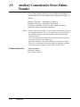
Product service
Panasonic Factory Servicenters for this product are listed in the servicenter directory.
Consult your authorized Panasonic dealer for detailed instructions.
For your future reference
DATE OF PURCHASE
NAME OF DEALER
DEALER’S ADDRESS
DEALER’S TEL NO.
4
Important Safety Instructions
When using your telephone equipment, basic safety precautions should
always be followed to reduce the risk of fire, electric shock and injury to
persons, including the following:
1. Read and understand all instructions.
2. Follow all warnings and instructions marked on the product.
3. Unplug this product from the wall outlet before cleaning. Do not use
liquid cleaners or aerosol cleaners. Use a damp cloth for cleaning.
4. Do not use this product near water, for example, near a bathtub, wash
bowl, kitchen sink, or laundry tub, in a wet basement, or near a
swimming pool.
5. Do not place this product on an unstable cart, stand, or table. The
product may fall, causing serious damage to the product.
6. Slots and openings in the cabinet and the back or bottom are provided
for ventilation, to protect it from overheating, these openings must not
be blocked or covered. The openings should never be blocked by
placing the product on the bed, sofa, rug, or other similar surface. This
product should never be placed near or over a radiator or heat register.
This product should not be placed in a built-in installation unless
proper ventilation is provided.
7. This product should be operated only from the type of power source
indicated on the marking label. If you are not sure of the type of power
supply to your home, consult your dealer or local power company.
8. This product is equipped with a three wire grounding type plug, a plug
having a third (grounding) pin. This plug will only fit into a grounding
type power outlet. This is a safety feature. If you are unable to insert
the plug into the outlet, contact your electrician to replace your
obsolete outlet. Do not defeat the safety purpose of the grounding type
plug.
9. Do not allow anything to rest on the power cord. Do not locate this
product where the cord will be abused by people walking on it.
10. Do not overload wall outlets and extension cords as this can result in
the risk of fire or electric shock.
5
Important Safety Instructions
11. Never push objects of any kind into this product through cabinet slots
as they may touch dangerous voltage points or short out parts that
could result in a risk of fire or electric shock. Never spill liquid of any
kind on the product.
12. To reduce the risk of electric shock, do not disassemble this product,
but take it to a qualified serviceman when some service or repair work
is required. Opening or removing covers may expose you to dangerous
voltages or other risks. Incorrect reassembly can cause electric shock
when the appliance is subsequently used.
13. Unplug this product from the wall outlet and refer servicing to qualified
service personnel under the following conditions:
A. When the power supply cord or plug is damaged or frayed.
B. If liquid has been spilled into the product.
C. If the product has been exposed to rain or water.
D. If the product does not operate normally by following the operating
instructions. Adjust only those controls, that are covered by the
operating instructions because improper adjustment of other
controls may result in damage and will often require extensive work
by a qualified technician to restore the product to normal operation.
E. If the product has been dropped or the cabinet has been damaged.
F. If the product exhibits a distinct change in performance.
14. Avoid using a telephone (other than a cordless type) during an
electrical storm. There may be a remote risk of electric shock from
lightning.
15. Do not use the telephone to report a gas leak in the vicinity of the leak.
SAVE THESE INSTRUCTIONS
6
Telephone Company and F.C.C.
Requirements and Responsibilities
1. Notification to the Telephone Company
Customers, before connecting terminal equipment to the telephone network, shall upon request of the
Telephone Company, inform the Telephone Company of the particular line(s) to which such
connection is made, the F.C.C. registration number (see the label on the bottom of the unit) and
ringer equivalence number (REN) of the registered terminal equipment.
The REN is useful in determining the quantity of devices you may connect to your telephone line and
still have all of those devices ring when your telephone number is called. In most, but not all areas,
the sum of the REN’s of all devices connected to one line should not exceed five (5.0). To be certain
of the number of devices you may connect to your line, as determined by the REN, you should
contact your local telephone company to determine the maximum REN for your calling area.
2. Connection to Telephone Line
This unit must not be connected to a coin operated line. If you are on a party line, check with your
local telephone company.
3. Incidence of Harm to the Telephone Lines
Should terminal equipment cause harm to the telephone network, the telephone company shall,
where practical, notify the customer that temporary discontinuance of service may be required.
However, where prior notice is not practical, the telephone company may temporarily discontinue
service forthwith, if such action is reasonable in the circumstances. In case of such unnotified
temporary discontinuance of service, the telephone company shall:
(a) Promptly notify the customer of such temporary discontinuance of service.
(b) Afford the customer the opportunity to correct the situation which gave rise to the temporary
discontinuance.
(c) Inform the customer of the right to bring a complaint to the Federal Communication
Commission pursuant to the procedures set out in Subpart E of Part 68 of FCC Telephone
Equipment Rules.
4. Compatibility of the Telephone Network and Terminal Equipment
(a) Availability of telephone interface information.
Technical information concerning interface parameters and specifications not specified in FCC Rules,
including the number of Ringers which may be connected to a particular telephone line, which is
needed to permit Terminal Equipment to operate in a manner compatible with Telephone Company
communications facilities, shall be provided by the Telephone Company upon customer’s request.
(b) Changes in Telephone Company Communications Facilities, Equipment, Operations
and Procedures.
The Telephone Company may make changes in its communications facilities, equipment, operations
or procedures, where such action is reasonably required in the operation of its business and is not
inconsistent with the rules and regulations in FCC Part 68.
If such changes can be reasonably expected to render any customer Terminal Equipment
incompatible with Telephone Company Communications Facilities, or require modification or
alteration of such Terminal Equipment, or otherwise materially affect its use or performance, the
customer shall be given adequate notice in writing, to allow the customer an opportunity to maintain
uninterrupted service.
7
Telephone Company and F.C.C.
Requirements and Responsibilities
Notify the Telephone Company
Installation must be performed by a qualified professional installer.
Before connecting this equipment to any telephone, call the telephone company and inform them of
the following:
•
•
•
•
•
•
•
•
Telephone numbers to which the system will be connected
Make . . . . . . . . . . . . . . . . . . . . . . . . . . . . . . . . . . . . . Panasonic
Model . . . . . . . . . . . . . . . . . . . . . . . . . . . . . . . . . . . . KX-TA624
FCC Registration No. . . . . . . . . . . . . . . . . . . . . . . . found on the side of the unit
Ringer Equivalence No. . . . . . . . . . . . . . . . . . . . . . . found on the side of the unit
Facility Interface Code . . . . . . . . . . . . . . . . . . . . . . . 02LS2
Service Order Code . . . . . . . . . . . . . . . . . . . . . . . . . 9.0F
Required Network Interface Jack . . . . . . . . . . . . . . . RJ 11
Note :
This equipment has been tested and found to comply with the limits for a Class B digital device,
pursuant to Part 15 of the FCC Rules. These limits are designed to provide reasonable protection
against harmful interference in a residential installation. This equipment generates, uses and can
radiate radio frequency energy and, if not installed and used in accordance with the instructions, may
cause harmful interference to radio communications. However, there is no guarantee that interference
will not occur in a particular installation. If this equipment does cause harmful interference to radio
or television reception, which can be determined by turning the equipment off and on, the user is
encouraged to try to correct the interference by one or more of the following measures:
— Reorient or relocate the receiving antenna.
— Increase the separation between the equipment and receiver.
— Connect the equipment into an outlet on a circuit different from that to which the receiver is
connected.
— Consult the dealer or an experienced radio/TV technician for help.
Caution:
Any changes or modifications not expressly approved by the party responsible for compliance could
void the user’s authority to operate this device.
When programming emergency numbers and/or making test calls to emergency numbers:
1. Remain on the line and briefly explain to the dispatcher the reason for the call before hanging up.
2. Perform such activities in the off-peak hours, such as early morning hours or late evenings.
8
Introduction
This Installation Manual provides technical information for the Panasonic Advanced Hybrid
System, KX-TA624. It is designed to serve as an overall technical reference for the system
and includes a description of the system, its hardware and software, features and services
and environmental requirements.
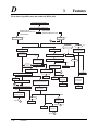
This manual contains the following sections.
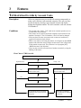
Section 1, System Outline
Provides general information on the system including system capacity and specifications.
Section 2, Installation
Contains the basic system installation and wiring instructions, as well as how to install the
optional cards and units.
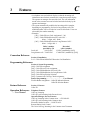
Section 3, Features
Describes all the basic, optional and programmable features in alphabetical order. It also
provides information about the programming required, conditions, connection references,
related features and operation for every feature.
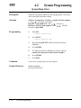
Section 4, System Programming
Provides step-by-step programming instructions for a proprietary telephone.
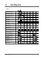
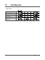
Section 5, List
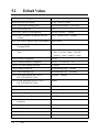
Lists the tone/ring tone and default values for system programming.
Section 6, Troubleshooting
Provides information for system and telephone troubleshooting.
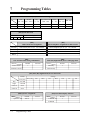
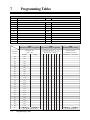
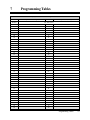
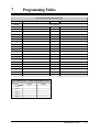
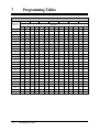
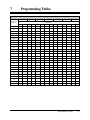
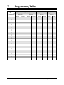
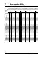
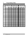
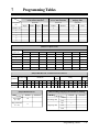
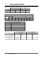
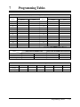
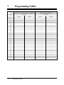
Section 7, Programming Tables
Provides a hard copy reference for entering user-programmed data.
NOTE
The following document may be used in conjunction with this manual.
• User Manual for the KX-TA624 System, Proprietary Telephones and Single Line
Telephones
9
Contents
Section 1
1.1
1.2
1.3
1.4
System Outline
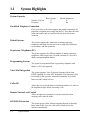
System Highlights RRRRRRRRRRRRRRRRRRRRR
Basic System Construction RRRRRRRRRRRRRRRRR
Proprietary Telephones RRRRRRRRRRRRRRRRRRR
Options RRRRRRRRRRRRRRRRRRRRRRRRRR
1-2
1-3
1-3
1-4
3 CO Line and 8 EXT Expansion Card (KX-TA62477) RRRRRRR
8 Extension Expansion Card (KX-TA62470) RRRRRRRRRRR
Caller ID Card (KX-TA62493) RRRRRRRRRRRRRRRR
OGM/FAX Detection Card (KX-TA62491) RRRRRRRRRRR
Doorphone/Door Opener Card (KX-TA62460) RRRRRRRRRR
DSS Console (KX-T7040) RRRRRRRRRRRRRRRRRR
1-4
1-4
1-4
1-4
1-5
1-5
1.4.1
1.4.2
1.4.3
1.4.4
1.4.5
1.4.6
1.5
Specifications RRRRRRRRRRRRRRRRRRRRRRR 1-6
1.5.1
1.5.2
1.5.3
Section 2
2.1
2.2
Installation
Before Installation RRRRRRRRRRRRRRRRRRRRR 2-2
Installation of the Main Unit RRRRRRRRRRRRRRRRR 2-4
2.2.1
2.2.2
2.2.3
2.2.4
2.3
2.3.8
2.3.9
System Connection Diagram RRRRRRRRRRRRRRRRR 2-7
Opening the Front Cover RRRRRRRRRRRRRRRRRRR 2-8
Outside (CO) Line Connection RRRRRRRRRRRRRRRR 2-9
Extension Connection RRRRRRRRRRRRRRRRRRR 2-12
External Pager (Paging Equipment) Connection RRRRRRRRR 2-13
External Music Source Connection RRRRRRRRRRRRRR 2-14
Paralleled Telephone Connection
(for a Proprietary Telephone and a Single Line Telephone) RRRR 2-15
Polarity Sensitive Telephone Connection RRRRRRRRRRRR 2-16
Printer and PC Connection RRRRRRRRRRRRRRRRR 2-17
Location of Optional Cards RRRRRRRRRRRRRRRRR
Caller ID and OGM/FAX Detection Card Installation RRRRRRR
Doorphone and Door Opener Connection RRRRRRRRRRR
Installing a 3 CO Line and 8 EXT Expansion Card (KX-TA62477)
and 8 Extension Expansion Card (KX-TA62470) RRRRRRR
Securing the cords RRRRRRRRRRRRRRRRRRRRR
2-20
2-21
2-23
Auxiliary Connection for Power Failure Transfer RRRRRRRR
Closing the Front Cover RRRRRRRRRRRRRRRRRR
Starting the System for the First Time RRRRRRRRRRRR
System Restart RRRRRRRRRRRRRRRRRRRRRR
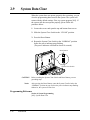
System Data Clear RRRRRRRRRRRRRRRRRRRR
2-34
2-35
2-36
2-37
2-38
2.4.5
10
2-4
2-4
2-5
2-6
Installation of Optional Cards RRRRRRRRRRRRRRRR 2-20
2.4.1
2.4.2
2.4.3
2.4.4
2.5
2.6
2.7
2.8
2.9
Unpacking RRRRRRRRRRRRRRRRRRRRRRRR
Location of Interfaces RRRRRRRRRRRRRRRRRRRR
Wall Mounting RRRRRRRRRRRRRRRRRRRRRR
Frame Ground Connection RRRRRRRRRRRRRRRRRR
Connection RRRRRRRRRRRRRRRRRRRRRRRR 2-7
2.3.1
2.3.2
2.3.3
2.3.4
2.3.5
2.3.6
2.3.7
2.4
General Description RRRRRRRRRRRRRRRRRRRR 1-6
Characteristics RRRRRRRRRRRRRRRRRRRRRRR 1-7
System Capacity RRRRRRRRRRRRRRRRRRRRRR 1-8
2-28
2-33
Contents
Section 3
A
B
C
D
Features
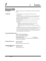
Absent Message Capability RRRRRRRRRRRRRRRRRRRRR 3-2
Account Code Entry RRRRRRRRRRRRRRRRRRRRRRRR 3-3
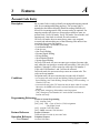
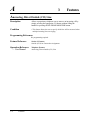
Answering, Direct Outside (CO) Line RRRRRRRRRRRRRRRRR 3-4
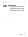
Automatic Callback Busy (Camp-On) RRRRRRRRRRRRRRRRR 3-5
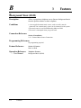
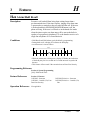
Background Music (BGM) RRRRRRRRRRRRRRRRRRRRR 3-6
Busy Lamp Field RRRRRRRRRRRRRRRRRRRRRRRRR 3-7
Busy Station Signaling (BSS) RRRRRRRRRRRRRRRRRRRR 3-7
Button, Direct Station Selection (DSS) RRRRRRRRRRRRRRRRR 3-8
Button, Flexible RRRRRRRRRRRRRRRRRRRRRRRRRR 3-9
Button, Group-CO (G-CO) RRRRRRRRRRRRRRRRRRRRR 3-11
Button, Other-CO (O-CO) RRRRRRRRRRRRRRRRRRRRR 3-12
Button, Single-CO (S-CO) RRRRRRRRRRRRRRRRRRRRR 3-13
Buttons on Proprietary Telephones RRRRRRRRRRRRRRRRRR 3-14
CALL FORWARDING FEATURES – SUMMARY RRRRRRRRRRR 3-16
Call Forwarding – All Calls RRRRRRRRRRRRRRRRRRRR 3-16
Call Forwarding – Busy/No Answer RRRRRRRRRRRRRRRRR 3-17
Call Forwarding – Follow Me RRRRRRRRRRRRRRRRRRRR 3-18
Call Forwarding – to an Outside (CO) Line RRRRRRRRRRRRRR 3-19
Call Hold – Intercom RRRRRRRRRRRRRRRRRRRRRRR 3-20
Call Hold – Outside (CO) Line RRRRRRRRRRRRRRRRRRR 3-21
Call Hold, Exclusive – Intercom RRRRRRRRRRRRRRRRRRR 3-22
Call Hold, Exclusive – Outside (CO) Line RRRRRRRRRRRRRRR 3-22
Call Hold Retrieve – Intercom RRRRRRRRRRRRRRRRRRR 3-23
Call Hold Retrieve – Outside (CO) Line RRRRRRRRRRRRRRRR 3-23
Call Log, Incoming RRRRRRRRRRRRRRRRRRRRRRRR 3-24
Call Park RRRRRRRRRRRRRRRRRRRRRRRRRRRR 3-26
Call Pickup, Directed RRRRRRRRRRRRRRRRRRRRRRR 3-26
Call Pickup, Group RRRRRRRRRRRRRRRRRRRRRRRR 3-27
Call Pickup Deny RRRRRRRRRRRRRRRRRRRRRRRR 3-27
Call Retrieving from a TAM (Telephone Answering Machine) RRRRRRR 3-28
Call Splitting RRRRRRRRRRRRRRRRRRRRRRRRRR 3-28
CALL TRANSFER FEATURES – SUMMARY RRRRRRRRRRRR 3-29
Call Transfer, Screened – to Extension RRRRRRRRRRRRRRRR 3-29
Call Transfer, Screened – to an Outside (CO) Line RRRRRRRRRRR 3-30
Call Transfer, Unscreened – to Extension RRRRRRRRRRRRRRR 3-31
Call Waiting RRRRRRRRRRRRRRRRRRRRRRRRRR 3-32
Call Waiting from a Central Office RRRRRRRRRRRRRRRRRR 3-33
Caller ID RRRRRRRRRRRRRRRRRRRRRRRRRRRR 3-34
Caller ID Call Waiting RRRRRRRRRRRRRRRRRRRRRR 3-35
Calling Party Control (CPC) Signal Detection RRRRRRRRRRRRR 3-36
Conference RRRRRRRRRRRRRRRRRRRRRRRRRRR 3-37
Conference, Unattended RRRRRRRRRRRRRRRRRRRRRR 3-38
Confirmation Tones RRRRRRRRRRRRRRRRRRRRRRRR 3-39
Data Line Security RRRRRRRRRRRRRRRRRRRRRRRR 3-41
Dial Tones, Distinctive RRRRRRRRRRRRRRRRRRRRRR 3-42
Dial Type Selection RRRRRRRRRRRRRRRRRRRRRRRR 3-43
11
Contents
E
F
H
I
L
M
O
12
Direct In Lines (DIL) RRRRRRRRRRRRRRRRRRRRRRR 3-44
Direct Inward System Access (DISA) RRRRRRRRRRRRRRRR 3-45
Display, Call Information RRRRRRRRRRRRRRRRRRRRR 3-51
Display, in Idle RRRRRRRRRRRRRRRRRRRRRRRRR 3-52
Display, Self-Extension Number RRRRRRRRRRRRRRRRRRR 3-53
Display Contrast Adjustment RRRRRRRRRRRRRRRRRRRR 3-53
Do Not Disturb (DND) RRRRRRRRRRRRRRRRRRRRRR 3-54
Do Not Disturb (DND) Override RRRRRRRRRRRRRRRRRR 3-54
Door Opener RRRRRRRRRRRRRRRRRRRRRRRRRR 3-55
Doorphone Call RRRRRRRRRRRRRRRRRRRRRRRRR 3-56
DSS Console (KX-T7040) RRRRRRRRRRRRRRRRRRRRR 3-57
Electronic Station Lockout RRRRRRRRRRRRRRRRRRRRR 3-60
Emergency Call RRRRRRRRRRRRRRRRRRRRRRRRR 3-61
End-to-End DTMF Signaling (Tone Through) RRRRRRRRRRRRR 3-61
Executive Busy Override – Extension RRRRRRRRRRRRRRRR 3-62
Executive Busy Override – Outside (CO) Line RRRRRRRRRRRRR 3-63
Extension Group RRRRRRRRRRRRRRRRRRRRRRRRR 3-64
External Feature Access RRRRRRRRRRRRRRRRRRRRRR 3-65
Facsimile Detection RRRRRRRRRRRRRRRRRRRRRRRR 3-66
Flash RRRRRRRRRRRRRRRRRRRRRRRRRRRRR 3-66
Handset/Headset Selection RRRRRRRRRRRRRRRRRRRRR 3-67
Hands-free Answerback RRRRRRRRRRRRRRRRRRRRRR 3-67
Hands-free Operation RRRRRRRRRRRRRRRRRRRRRRR 3-68
Hold Alarm/Hold Recall RRRRRRRRRRRRRRRRRRRRRR 3-69
Host PBX Access RRRRRRRRRRRRRRRRRRRRRRRR 3-70
Intercept Routing RRRRRRRRRRRRRRRRRRRRRRRRR 3-71
Intercom Calling RRRRRRRRRRRRRRRRRRRRRRRRR 3-72
LED Indication, Intercom RRRRRRRRRRRRRRRRRRRRR 3-73
LED Indication, Outside (CO) Line RRRRRRRRRRRRRRRRR 3-74
Limited Call Duration RRRRRRRRRRRRRRRRRRRRRRR 3-75
Line Access, Automatic RRRRRRRRRRRRRRRRRRRRRR 3-76
Line Access, Direct RRRRRRRRRRRRRRRRRRRRRRRR 3-77
Line Access, Individual RRRRRRRRRRRRRRRRRRRRRR 3-78
Line Access, Outside (CO) Line Group RRRRRRRRRRRRRRRR 3-79
Line Preference – Incoming (No Line/Prime Line/Ringing Line) RRRRRR 3-80
Line Preference – Outgoing (Idle Line/No Line/Prime Line) RRRRRRRR 3-81
Live Call Screening (LCS) RRRRRRRRRRRRRRRRRRRRR 3-82
Lockout RRRRRRRRRRRRRRRRRRRRRRRRRRRR 3-84
Log-In/Log-Out RRRRRRRRRRRRRRRRRRRRRRRRR 3-85
Manager Extension RRRRRRRRRRRRRRRRRRRRRRRR 3-86
Message Waiting RRRRRRRRRRRRRRRRRRRRRRRRR 3-87
Message Waiting for Another Extension RRRRRRRRRRRRRRR 3-88
Microphone Mute RRRRRRRRRRRRRRRRRRRRRRRR 3-89
Mixed Station Capacities RRRRRRRRRRRRRRRRRRRRR 3-89
Module Expansion RRRRRRRRRRRRRRRRRRRRRRRR 3-90
Music on Hold RRRRRRRRRRRRRRRRRRRRRRRRRR 3-91
One-Touch Dialing RRRRRRRRRRRRRRRRRRRRRRRR 3-92
One-Touch Transfer Using a DSS Button RRRRRRRRRRRRRRR 3-93
Contents
P
R
S
T
V
W
Operator RRRRRRRRRRRRRRRRRRRRRRRRRRRR 3-94
Operator Call RRRRRRRRRRRRRRRRRRRRRRRRRR 3-94
Outgoing Message (OGM) RRRRRRRRRRRRRRRRRRRRR 3-95
Outside (CO) Line Connection Assignment RRRRRRRRRRRRRR 3-98
Outside (CO) Line Connection Assignment – Outgoing RRRRRRRRR 3-98
Outside (CO) Line Group RRRRRRRRRRRRRRRRRRRRR 3-99
PAGING FEATURES – SUMMARY RRRRRRRRRRRRRRRR 3-100
Paging – All RRRRRRRRRRRRRRRRRRRRRRRRRR 3-100
Paging – External RRRRRRRRRRRRRRRRRRRRRRRR 3-101
Paging – Group RRRRRRRRRRRRRRRRRRRRRRRRR 3-101
Paralleled Telephone RRRRRRRRRRRRRRRRRRRRRRR 3-102
Pause Insertion, Automatic RRRRRRRRRRRRRRRRRRRR 3-103
Personal Speed Dialing RRRRRRRRRRRRRRRRRRRRRR 3-104
Pickup Dialing RRRRRRRRRRRRRRRRRRRRRRRRR 3-105
Power Failure Transfer RRRRRRRRRRRRRRRRRRRRRR 3-106
Pulse to Tone Conversion RRRRRRRRRRRRRRRRRRRRR 3-107
Redial, Last Number RRRRRRRRRRRRRRRRRRRRRRR 3-108
Redial, Saved Number RRRRRRRRRRRRRRRRRRRRRR 3-108
Remote Station Lock Control RRRRRRRRRRRRRRRRRRR 3-109
Ring Group RRRRRRRRRRRRRRRRRRRRRRRRRR 3-110
Ringing, Delayed RRRRRRRRRRRRRRRRRRRRRRRR 3-110
Ringing, Discriminating RRRRRRRRRRRRRRRRRRRRR 3-111
Ringing Pattern Selection for Intercom Calls and Outside (CO) Lines RRR 3-112
Ringing Tone Selection for Doorphones RRRRRRRRRRRRRRR 3-113
Room Monitor RRRRRRRRRRRRRRRRRRRRRRRRR 3-114
Secret Dialing RRRRRRRRRRRRRRRRRRRRRRRRR 3-115
Station Feature Clear RRRRRRRRRRRRRRRRRRRRRRR 3-116
Station Hunting RRRRRRRRRRRRRRRRRRRRRRRRR 3-117
Station Message Detail Recording (SMDR) RRRRRRRRRRRRRR 3-118
Station Programming RRRRRRRRRRRRRRRRRRRRRR 3-120
Station Programming Data Default Set RRRRRRRRRRRRRRRR 3-121
System Data Default Set RRRRRRRRRRRRRRRRRRRRR 3-122
System Programming with a Proprietary Telephone RRRRRRRRRR 3-122
System Speed Dialing RRRRRRRRRRRRRRRRRRRRRR 3-123
Time (Day/Night/Lunch) Service RRRRRRRRRRRRRRRRRR 3-124
Time-Out, Variable RRRRRRRRRRRRRRRRRRRRRRR 3-126
Timed Reminder RRRRRRRRRRRRRRRRRRRRRRRR 3-128
Timed Reminder, Remote (Wake-Up Call) RRRRRRRRRRRRRR 3-128
Toll Restriction RRRRRRRRRRRRRRRRRRRRRRRRR 3-129
Toll Restriction for Special Carrier Access RRRRRRRRRRRRRR 3-135
Toll Restriction for System Speed Dialing RRRRRRRRRRRRRR 3-136
Toll Restriction Override by Account Codes RRRRRRRRRRRRR 3-137
Toll Restriction — Station Lock Boundary Class RRRRRRRRRRRR 3-139
Two-Way Recording into Voice Mail RRRRRRRRRRRRRRRR 3-140
Voice Mail Integration for KX-TVS50/KX-TVS80 RRRRRRRRRRR 3-141
Voice Mail Integration for KX-TVS75/KX-TVS100/KX-TVS110 RRRRR 3-146
Volume Control – Handset Receiver/Headset/Ringer/Speaker RRRRRRR 3-150
Walking COS RRRRRRRRRRRRRRRRRRRRRRRRR 3-151
13
Contents
Section 4
4.1
System Programming
General Programming Instructions RRRRRRRRRRRRRR 4-2
4.1.1
4.1.2
4.1.3
4.1.4
4.2
System Programming RRRRRRRRRRRRRRRRRRRR 4-9
[000]
[001]
[002]
[003]
[004]
[005]
[006]
[007]
[008]
[009]
[010]
[100]
[101]
[102]
[103]
[104]
[105]
[106]
[107]
[108]
[109]
[110]
[111]
[112]
[115]
[117]
[118]
[119]
[125]
[130]
[131]
[200]
[201]
[202]
[203]
[204]
[205]
[206]
[208]
14
Using Proprietary Telephones RRRRRRRRRRRRRRRRR 4-3
Programming Methods RRRRRRRRRRRRRRRRRRRR 4-5
Entering Characters RRRRRRRRRRRRRRRRRRRRR 4-6
Programming Example RRRRRRRRRRRRRRRRRRR 4-8
Date and Time Setting RRRRRRRRRRRRRRRRRRRR 4-9
System Speed Dialing Entry RRRRRRRRRRRRRRRRR 4-11
System Password RRRRRRRRRRRRRRRRRRRRR 4-13
DSS Console Port Assignment RRRRRRRRRRRRRRRR 4-14
Paired Telephone Assignment for DSS Console RRRRRRRRR 4-15
One-Touch Transfer Using a DSS Button RRRRRRRRRRRR 4-16
Time (Day/Night/Lunch) Service Changing Mode RRRRRRRR 4-17
Time (Day/Night/Lunch) Service Start Time RRRRRRRRRRR 4-18
Operator Assignment RRRRRRRRRRRRRRRRRRRR 4-20
Extension Number Assignment RRRRRRRRRRRRRRRR 4-21
LCD Time Display Selection RRRRRRRRRRRRRRRRR 4-22
Hunting Group Set RRRRRRRRRRRRRRRRRRRRR 4-23
Station Hunting Type RRRRRRRRRRRRRRRRRRRR 4-24
Voice Mail Port for KX-TVS75/KX-TVS100/KX-TVS110 RRRRR 4-25
DTMF Integration for KX-TVS75/KX-TVS100/KX-TVS110 RRRR 4-26
Hold Mode Selection RRRRRRRRRRRRRRRRRRRR 4-28
Conference Tone RRRRRRRRRRRRRRRRRRRRR 4-29
External Paging Access Tone RRRRRRRRRRRRRRRRR 4-30
DTMF Receiver Check RRRRRRRRRRRRRRRRRRR 4-31
Flash Mode for a Station Locked Extension RRRRRRRRRRR 4-32
CO Indicator Assignment RRRRRRRRRRRRRRRRRR 4-33
Flash Key Mode RRRRRRRRRRRRRRRRRRRRRR 4-34
Hold Music Selection RRRRRRRRRRRRRRRRRRRR 4-35
DSS Console Indication Mode RRRRRRRRRRRRRRRR 4-36
Extension Ringing Pattern Selection RRRRRRRRRRRRRR 4-37
Call Pickup Tone RRRRRRRRRRRRRRRRRRRRR 4-38
Pulse Restriction RRRRRRRRRRRRRRRRRRRRR 4-39
Redialing After Pulse to Tone Conversion RRRRRRRRRRRR 4-40
Toll Restriction Check for
and # RRRRRRRRRRRRRR 4-41
Voice Mail 1 APT Port for KX-TVS50/KX-TVS80 RRRRRRRR 4-42
Voice Mail 2 APT Port for KX-TVS50/KX-TVS80 RRRRRRRR 4-43
Hold Recall Time RRRRRRRRRRRRRRRRRRRRR 4-44
Transfer Recall Time RRRRRRRRRRRRRRRRRRRR 4-45
Call Forwarding Start Time RRRRRRRRRRRRRRRRR 4-46
Pickup Dial Delay Time RRRRRRRRRRRRRRRRRRR 4-47
Call Duration Count Start Time RRRRRRRRRRRRRRRR 4-48
Outside-to-Outside (CO-to-CO) Line Duration Time Limit RRRRR 4-49
Dialing Start Time RRRRRRRRRRRRRRRRRRRRR 4-50
Interdigit Time RRRRRRRRRRRRRRRRRRRRRR 4-51
Contents
[211] No Dial Disconnection RRRRRRRRRRRRRRRRRRR 4-52
[300] Carrier Code Assignment RRRRRRRRRRRRRRRRRR 4-53
[301] Toll Restriction — System Speed Dialing Boundary Class RRRRR 4-54
[302]–[305] Toll Restriction — Class 2 – 5 Denied Codes RRRRRRRR 4-55
[306] Toll Restriction — Exception Codes RRRRRRRRRRRRRR 4-56
[309] Emergency Dial Number Set RRRRRRRRRRRRRRRRR 4-57
[310] Account Codes RRRRRRRRRRRRRRRRRRRRRR 4-58
[311] Automatic Pause Insertion Codes RRRRRRRRRRRRRRR 4-59
[312] Toll Restriction — Station Lock Boundary Class RRRRRRRRR 4-60
[400] Outside (CO) Line Connection Assignment RRRRRRRRRRR 4-61
[401] Dial Mode RRRRRRRRRRRRRRRRRRRRRRRR 4-62
[402] Pulse Speed Selection RRRRRRRRRRRRRRRRRRR 4-63
[403] Host PBX Access Codes RRRRRRRRRRRRRRRRRR 4-64
[404] Outside (CO) Line Group Assignment RRRRRRRRRRRRR 4-66
[405]–[407] Flexible Outward Dialing Assignment — Day/Night/Lunch RR 4-67
[408]–[410] Flexible Ringing Assignment — Day/Night/Lunch RRRRRR 4-68
[411]–[413] Delayed Ringing Assignment — Day/Night/Lunch RRRRRR 4-70
[414]–[416] Outside (CO) Line Mode — Day/Night/Lunch RRRRRRRR 4-72
[417] Pause Time RRRRRRRRRRRRRRRRRRRRRRRR 4-74
[418] Flash Time RRRRRRRRRRRRRRRRRRRRRRRR 4-75
[419] Automatic Designated Outside (CO) Line Access RRRRRRRR 4-76
[420] Calling Party Control (CPC) Signal RRRRRRRRRRRRRR 4-77
[421] CPC Detection for Outgoing Calls RRRRRRRRRRRRRR 4-79
[422] Disconnect Time RRRRRRRRRRRRRRRRRRRRR 4-80
[423] Outside (CO) Line Ringing Pattern Selection RRRRRRRRRR 4-81
[500] DISA Incoming Dialing Mode Selection RRRRRRRRRRRR 4-82
[501] DISA Built-in Auto Attendant RRRRRRRRRRRRRRRR 4-83
[502] OGM Mode Selection RRRRRRRRRRRRRRRRRRR 4-84
[503] FAX Connection RRRRRRRRRRRRRRRRRRRRR 4-85
[504] DISA Delayed Answer Time RRRRRRRRRRRRRRRRR 4-86
[505] DISA Waiting Time after OGM RRRRRRRRRRRRRRRR 4-87
[506] DISA Busy Mode RRRRRRRRRRRRRRRRRRRRR 4-88
[507] DISA Intercept Mode RRRRRRRRRRRRRRRRRRRR 4-89
[508] DISA Ringing Time before Intercept RRRRRRRRRRRRRR 4-90
[509] DISA Ringing Time after Intercept RRRRRRRRRRRRRR 4-91
[510] DISA No Dial Mode RRRRRRRRRRRRRRRRRRRR 4-92
[511] DISA Security Type RRRRRRRRRRRRRRRRRRRR 4-93
[512] DISA Security Codes RRRRRRRRRRRRRRRRRRRR 4-94
[513] Cyclic Tone Detection RRRRRRRRRRRRRRRRRRR 4-95
[514] FAX Tone Detection RRRRRRRRRRRRRRRRRRRR 4-96
[515] Intercept Time for Internal DISA RRRRRRRRRRRRRRR 4-97
[516] DISA Incoming Assignment RRRRRRRRRRRRRRRRR 4-98
[517] DISA AA Wait Time RRRRRRRRRRRRRRRRRRRR 4-99
[518] DISA Tone Selection after the Security Code RRRRRRRRRR 4-100
[530] DISA Security Codes Digits Selection RRRRRRRRRRRR 4-101
[600] Extension Group Assignment RRRRRRRRRRRRRRRR 4-102
[601]–[603] TRS – Class of Service (COS) Assignment
— Day/Night/Lunch RRRRRRRRRRRRRRRR 4-103
15
Contents
[604] Extension Name Setting RRRRRRRRRRRRRRRRRR 4-104
[605] Account Code Entry Mode RRRRRRRRRRRRRRRRR 4-105
[606] Call Transfer to an Outside (CO) Line RRRRRRRRRRRRR 4-107
[607] Call Forwarding to an Outside (CO) Line RRRRRRRRRRR 4-108
[608] Executive Busy Override RRRRRRRRRRRRRRRRRR 4-109
[609] Do Not Disturb Override RRRRRRRRRRRRRRRRRR 4-110
[610] Paralleled Telephone Connection RRRRRRRRRRRRRRR 4-111
[611] TAM (Telephone Answering Machine) Extension RRRRRRRR 4-112
[612] Room Monitor Assignment RRRRRRRRRRRRRRRRR 4-113
[617] Wireless PT Port Assignment RRRRRRRRRRRRRRRR 4-114
[618] Message Waiting for Another Extension RRRRRRRRRRRR 4-115
[620] Live Call Screening Recording Mode Assignment RRRRRRRR 4-116
[700]–[702] Doorphone Ringing Assignment — Day/Night/Lunch RRRR 4-117
[703]–[705] Door Opener Assignment — Day/Night/Lunch RRRRRRR 4-118
[706] Doorphone Ringing/Tone Pattern Selection RRRRRRRRRR 4-119
[707] Doorphone Access Tone Selection RRRRRRRRRRRRRR 4-120
[708] Doorphone Ringing Time RRRRRRRRRRRRRRRRR 4-121
[709] Door Opener Time RRRRRRRRRRRRRRRRRRRR 4-122
[800] SMDR RS-232C Communication Parameters RRRRRRRRRR 4-123
[801] SMDR Parameter RRRRRRRRRRRRRRRRRRRRR 4-125
[802] Incoming/Outgoing Call Selection for Printing RRRRRRRRR 4-126
[803] Secret Speed Dialing/One-Touch Dialing Printing RRRRRRRR 4-127
[804] System Data Dump RRRRRRRRRRRRRRRRRRRR 4-128
[805] SMDR Account Code Selection RRRRRRRRRRRRRRR 4-130
[900] Caller ID Assignment RRRRRRRRRRRRRRRRRRR 4-131
[901] Caller ID Area Code Assignment RRRRRRRRRRRRRR 4-132
[902] Caller ID Modification for Local Calls RRRRRRRRRRRR 4-133
[903] Caller ID Modification for Long Distance Calls RRRRRRRRR 4-134
[904] Caller ID Log Priority Selection RRRRRRRRRRRRRRR 4-135
[906] Caller ID SMDR Format RRRRRRRRRRRRRRRRRR 4-136
[907] Caller ID SMDR Printout Selection RRRRRRRRRRRRR 4-137
[908] Caller ID Call Waiting Time RRRRRRRRRRRRRRRR 4-138
[909] Common Area Call Log Check Assignment RRRRRRRRRR 4-139
[963] Call Forwarding Selection RRRRRRRRRRRRRRRRR 4-140
[998] ROM Version RRRRRRRRRRRRRRRRRRRRRR 4-141
[999] System Data Clear RRRRRRRRRRRRRRRRRRRR 4-142
Section 5
5.1
5.2
Section 6
6.1
6.2
6.3
Section 7
16
List
Tone/Ring Tone RRRRRRRRRRRRRRRRRRRRRR 5-2
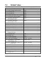
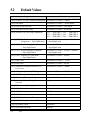
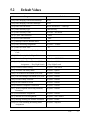
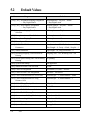
Default Values RRRRRRRRRRRRRRRRRRRRRRR 5-4
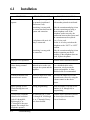
Troubleshooting
Installation RRRRRRRRRRRRRRRRRRRRRRRR 6-2
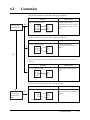
Connection RRRRRRRRRRRRRRRRRRRRRRRR 6-3
Operation RRRRRRRRRRRRRRRRRRRRRRRRR 6-4
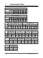
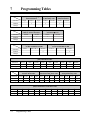
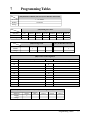
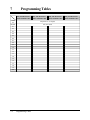
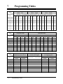
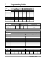
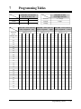
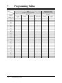
Programming Tables
Section 1
System Outline
This section provides general information on the system,
including system capacity and specifications.
1.1
System Highlights
System Capacity
Outside (CO) line
Extension
Basic System
3
8
Module Expansion
3
16
Paralleled Telephone Connection
Every jack in the system also supports the parallel connection of a
proprietary telephone and a single line device. They share the same
extension number and are considered by the system to be one
extension.
Hybrid System
This system supports the connection of analog proprietary
telephones and single line devices such as single line telephones,
fax machines, and data terminals.
Proprietary Telephones (PT)
The system supports five different models of analog proprietary
telephones which range from a set with a monitor to a set with a
display and speakerphone button.
Programming System
The system is programmed from a proprietary telephone with
display. A PC is not required.
Voice Mail Integration
The system supports Voice Processing Systems with in-band
DTMF signaling as well as APT Integration. The Panasonic Voice
Processing System provides Automated Attendant, Voice Mail,
Interview and Custom Services.
Caller ID
Allows the user to see the name or telephone number of a caller on
the telephone display before answering a call.
Remote Station Lock Control
Allows an operator or manager to lock an extension so that
outgoing calls cannot be made.
OGM/FAX Detection
The system greets callers with an Outgoing Message so that they
know what to dial. Also, fax calls can be routed to your fax
machine automatically.
1-2
System Outline
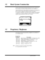
1.2
Basic System Construction
The KX-TA624 Advanced Hybrid System has a basic capacity of
three outside (CO) lines and eight extensions. It is capable of
supporting Panasonic analog proprietary telephones, and single line
devices such as single line telephones and a fax machine.
To expand its capabilities, the system can be equipped with optional
components or customer-supplied peripherals such as an external
speaker and external music source (e.g., a radio).
1.3
Proprietary Telephones
The following Panasonic proprietary telephones are available for
use with this system.
Proprietary
Telephone
KX-T7135
KX-T7130
KX-T7020
KX-T7030
KX-T7050
KX-T7055
Description
Backlit Display, Speakerphone, 12 Flexible CO, 12 PF
Display, Speakerphone, 12 Flexible CO, 12 PF
Speakerphone, 12 Flexible CO, 4 PF
Display, Speakerphone, 12 Flexible CO, 4 PF
Monitor, 12 Flexible CO, 4 PF
Monitor, 3 Flexible CO, 3 PF
Note: Flexible CO: Flexible CO button (programmable)
PF: Programmable Feature button
System Outline
1-3
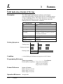
1.4
1.4.1
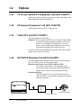
Options
3 CO Line and 8 EXT Expansion Card (KX-TA62477)
Adds three outside (CO) lines (outside (CO) lines 4 through 6) and
eight extensions (JACK 09 through 16).
1.4.2
8 Extension Expansion Card (KX-TA62470)
Adds eight extensions (JACK 17 through 24).
1.4.3
Caller ID Card (KX-TA62493)
This card supports the following.
Caller ID: Receives the Caller ID Service from the Central Office.
A specified display proprietary telephone with Caller
ID service can display the information. It can also
display caller’s information which has been stored in
the system according to the Caller ID service.
Up to two cards can be installed to the system. One Caller ID card
supports three outside (CO) lines.
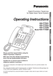
1.4.4
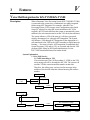
OGM/FAX Detection Card (KX-TA62491)
This card supports the following. There are two circuits, therefore
up to two calls can be received simultaneously.
Direct Inward System Access (DISA) with an OGM:
One of the system features. An outgoing message
greets the external caller and provides information so
that the caller can access the extension(s) directly.
Facsimile detection:
When the system receives a facsimile transmission
signal by DISA, it automatically connects the specified
facsimile extension.
Central
Office
External Telephone
Outside (CO) Line
1-4
System Outline
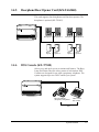
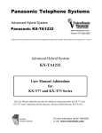
1.4.5
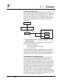
Doorphone/Door Opener Card (KX-TA62460)
This card supports four doorphones and four door openers. The
doorphone is optional (KX-T30865).
Panasonic
Panasonic
Doorphone 1 Doorphone 2
Door
Opener 1
1.4.6
Door
Opener 2
Panasonic
Panasonic
Doorphone 3 Doorphone 4
Door
Opener 3
Door
Opener 4
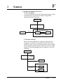
DSS Console (KX-T7040)
Allows easy and quick access to stations and features. The Busy
Lamp Field shows the idle or busy status of each station. DSS
Consoles are designed for use with a proprietary telephone. The
system supports up to two DSS Consoles per system.
Pan
ason
ic
Paired Telephone
(Proprietary Telephone)
DSS Console
KX-T7040
Pair
System Outline
1-5
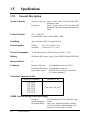
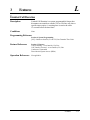
1.5
Specifications
1.5.1
General Description
System Capacity
Outside (CO) Lines 3 max. (6 max. with a 3 CO Line and 8 EXT
Expansion Card)
Extensions
8 max. (24 max. with a 3 CO Line and 8 EXT
Expansion Card and 8 Extension Expansion
Card)
Control Method
CPU: 16 bit CPU
Control ROM: 4 Mbit, Control RAM; 1 Mbit
Switching
Space Division CMOS Crosspoint Switch
Power Supplies
Primary
Secondary
Power Consumption
45 W (When power is off by the Power Switch: 1.2 W)
Dialing
Dial Pulse (DP) 10 pps, 20 pps, Tone (DTMF) Dialing, DTMF-DP
Intercom Paths
4
Connector
Outside (CO) Lines
2-pin Modular Connector (RJ11)
Extensions/Doorphone 4-pin Modular Connector
Pager/Music Source
EIAJ RC-6701 A plug (two-conductor,
ø 3.5 mm in diameter)
120 V AC, 60 Hz (1.2 A)
Circuit Volt: +5 V, +26 V
Extension Connection Cable
Single Line Telephone
1 pair wire (T, R)
KX-T7020
KX-T7030
KX-T7050
KX-T7055
KX-T7130
KX-T7135
2 pair wire (T, R, H, L)
SMDR (Station Message Detail Recording)
Interface
Output Equipment
Recording Details
1-6
System Outline
Serial Interface (RS-232C) (D-SUB, 9-pin)
Printer
Date, Time, Extension Number, Outside
(CO) Line Number, Dialed Number, Call
Duration, Account Code, Caller ID
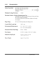
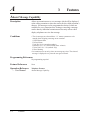
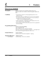
1.5.2
Characteristics
Station Loop Limit
KX-T7020 / KX-T7030 / KX-T7050 /
KX-T7055 / KX-T7130 / KX-T7135 . . . . . . . . . . . . . . . . . . . 40 Ω
Single Line Telephone . . . . . . . . . . . . . . . . . . . 600 Ω including set
Doorphone . . . . . . . . . . . . . . . . . . . . . . . . . . . . . . . . . . . . . . . 20 Ω
Minimum Leakage Resistance
15 000 Ω
Maximum Number of Station Instruments per Line
1 for a KX-T7135, KX-T7130, KX-T7020, KX-T7030, KX-T7050,
KX-T7055 or single line telephone
2 by Parallel Connection of a proprietary telephone and a single
line telephone
Ring Voltage
80 Vrms at 20 Hz depending on the Ringing Load
Central Office Loop Limit
1 600 Ω max.
Environmental Requirements
0 °C – 40 °C {32 °F – 104 °F},
10 % – 90 % relative humidity
Hookswitch Flash Time Range
204 ms – 1 000 ms
Door Opener
30 V DC, 5 A (Max) / 120 V AC, 5 A (Max)
Dimensions (H k W k D)
284 mm k 368 mm k 95 mm
{111/8q k 141/2q k 33/4q}
Mass (Weight)
Approx. 2.5 kg {5.6 lb}
System Outline
1-7
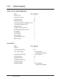
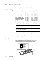
1.5.3
System Capacity
Lines, Cards, Station Equipment
Item
Max. Quantity
Service Units
1
Outside (CO) Lines
6
Extension Jacks
24
Station Terminals
48
3 CO Line and 8 EXT Expansion Card 1
8 Extension Expansion Card
1
Caller ID Card
2
OGM/FAX Detection Card
1
Doorphone/Door Opener Card
1
Doorphones
4
Door Openers
4
External Pager
1
External Music Source
1
DSS Consoles
2
System Data
Item
Operator
System Speed Dialing
One-Touch Dialing
Personal Speed Dialing
Call Park Areas
Absent Messages
Toll Restriction Classes
Extension Groups
Message Waiting
1-8
System Outline
Max. Quantity
1
100
24 per extension
(proprietary telephone)
10 per extension
10
6
5
8
8 per extension
(proprietary telephone)
Section 2
Installation
This section contains the basic system installation and wiring instructions,
as well as how to install the optional cards and units.
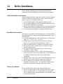
2.1
Before Installation
Please read the following notes concerning installation and
connection before installing the system and terminal equipment.
Safety Installation Instructions
When installing telephone wiring, basic safety precautions should
always be followed to reduce the risk of fire, electric shock and
injury to persons, including the following:
1. Never install telephone wiring during a lightning storm.
2. Never install telephone jacks in wet locations unless the jack is
specifically designed for wet locations.
3. Never touch uninsulated telephone wires or terminals unless the
telephone line has been disconnected at the network interface.
4. Use caution when installing or modifying telephone lines.
Installation Precautions
This system is designed for wall mounting only. Avoid installing in
the following places. (Doing so may result in malfunction, noise, or
discoloration.)
1. In direct sunlight and hot, cold, or humid places. (Temperature
range: 0 °C – 40 °C {32 °F – 104 °F})
2. Sulfuric gases produced in areas where there are thermal
springs, etc. may damage the equipment or contacts.
3. Places in which shocks or vibrations are frequent or strong.
4. Dusty places, or places where water or oil may come into
contact with the system.
5. Near high-frequency generating devices such as sewing
machines or electric welders.
6. On or near computers, telexes, or other office equipment, as
well as microwave ovens or air conditioners. (It is preferable not
to install the system in the same room with the above
equipment.)
7. Install at least 1.8 m {6 feet} away from radios and televisions.
(Both the system and Panasonic proprietary telephones)
8. Do not obstruct area around the system (for reasons of
maintenance and inspection — be especially careful to allow
space for cooling above and at the sides of the system).
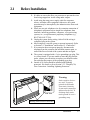
Wiring Precautions
Be sure to follow these instructions when wiring the unit:
1. Do not wire the telephone cable in parallel with an AC power
source, computer, telex, etc. If the cables are run near those
wires, shield the cables with metal tubing or use shielded cables
and ground the shields.
2-2
Installation
2.1
Before Installation
2. If cables are run on the floor, use protectors to prevent the wires
from being stepped on. Avoid wiring under carpets.
3. Avoid using the same power supply outlet for computers,
telexes, and other office equipment. Otherwise, the system
operation may be interrupted by the induction noise from such
equipment.
4. Please use one pair telephone wire for extension connection of
(telephone) equipment such as single line telephones, data
terminals, answering machines, computers, voice processing
systems, etc., except Panasonic proprietary telephones (e.g.,
KX-T7030, KX-T7130).
5. Unplug the system during wiring. After all of the wiring is
completed, plug in the system.
6. Mis-wiring may cause the system to operate improperly. Refer
to Section 6.1 “Installation” and Section 6.2 “Connection”.
7. If an extension does not operate properly, disconnect the
telephone from the extension line and then connect again, or
turn off the Power Switch of the system and then on again.
8. The system is equipped with a 3-wire grounding type plug. This
is a safety feature. If you are unable to insert the plug into the
outlet, contact your electrician to replace your obsolete outlet.
Do not defeat the purpose of the grounding-type plug.
9. Outside (CO) Lines should be installed with lightning
protectors. For details, refer to Section 2.3.3 “Outside (CO)
Line Connection – Installing Lightning Protectors”.
Warning:
ER
POW
Side View
Static sensitive devices
are used. To protect
printed circuit boards
from static electricity,
do not touch connectors
indicated to the left. To
discharge body static,
touch ground or wear a
grounding strap.
Warning: Static sensitive connectors
Installation
2-3
2.2
2.2.1
Installation of the Main Unit
Unpacking
Unpack the box and check the items below.
2.2.2
Main Unit
one
AC Cord
one
Screws (Wall Mounting)
three
Washers (Wall Mounting)
three
Pager Connector
one
Music Source Connector
one
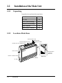
Location of Interfaces
External Music Jack
Paging Jack
Extension Modular Jacks
Strap (for cables)
Outside (CO) Line Modular Jacks
ER
POW
Power Switch
Serial Interface
Connector
(RS-232C)
Protective Earth Terminal
Side View
Power Indicator
AC Inlet
2-4
Installation
2.2.3
Wall Mounting
This set is designed for wall mounting only. The wall where the
main unit is to be mounted must be able to support the weight of
the main unit. If screws other than the ones supplied are used, use
screws with the same diameter as the ones enclosed.
Mounting on a Wooden Wall
Mounting on a Concrete or Mortar
Wall
1. Place the template (included) on the wall
to mark the screw positions.
1. Place the template (included) on the wall
to mark the screw positions.
2. Drill holes and drive the anchor plugs
(user-supplied) with a hammer, flush to
the wall.
To the wall surface
Concrete Wall
Anchor Plug
Template
6.4 mm
{1/4 inch}
29 mm
{1 1/8 inch}
2. Install the screws (included) into the
wall.
Wooden
Wall
3. Install the screws (included) into the
anchor plugs.
Drive the screw
to this position
Drive the screw
to this position
3. Hook the main unit on the screw heads.
4. Hook the main unit on the screw heads.
Installation
2-5
2.2.4
Frame Ground Connection
IMPORTANT!!!
Connect the frame of the main unit to the ground.
1. Loosen the screw.
2. Insert the grounding wire.
3. Tighten the screw.
4. Connect the grounding wire to the ground.
To the ground
Screw
In most of North America, the ground provided by the “Third wire ground” at the commercial or
residential power outlet will be satisfactory. However, in some cases this ground may be installed
incorrectly. Therefore, the following test procedure should be performed.
Test Procedure
1. Obtain a suitable voltmeter and set it for a possible reading of up to 250 V AC.
2. Connect the meter probes between the two main AC voltage points on the wall outlet. The
reading obtained should be 108 V AC – 132 V AC.
3. Move one of the meter probes to the 3rd prong terminal (GND).
Either the same reading or a reading of 0 V should be obtained.
4. If a reading of 0 V at one terminal and a reading of 108 V AC – 132 V AC at the other
terminal is not obtained, the outlet is not properly grounded.
This condition should be corrected by a qualified electrician (per article 250 of the National
Electrical Code).
5. If a reading of 0 V at one terminal and a reading of 108 V AC – 132 V AC at the other
terminal is obtained, then set the meter to the “OHMS/RX1” scale, place one probe at the
GND Terminal and the other probe at the terminal which gave a reading of 0 V.
A reading of less than 1 Ω should be obtained.
If the reading is not obtained, the outlet is not adequately grounded. See a qualified
electrician.
2-6
Installation
2.3
Connection
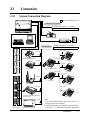
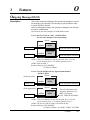
2.3.1
System Connection Diagram
: needs an Optional Card.
6 Outside (CO) Lines
to outside (CO) lines 1 – 3 (initial)
to outside (CO) lines 4 – 6 (additional)
(Lightning Protectors)
External Music Source
Amplifier
Printer
or
Computer
24 Extensions
Speaker
Extension jacks 01 – 08 (initial)
Extension jacks 09 – 24 (additional)
(two pair)
(one pair)
Single Line Telephone
(two pair)
KX-T7020
(one pair)
(two pair)
KX-T7130/KX-T7135
Data Terminal
(two pair)
KX-T7040
(two pair)
Door Openers
(one pair)
KX-T7030
Panasonic
Cordless Phone
KX-T7050
(one pair)
(two pair)
Panasonic
Panasonic
Telephone Answering Machine
with Facsimile
(one pair)
Panasonic
Doorphones
KX-T30865
Voice Processing System
KX-T7055
Note
• It is recommended that the extension of jack 01 is a
display proprietary telephone.
• Parallel connection of telephones is possible. Refer
to Section 2.3.7, “Paralleled Telephone Connection”.
Installation
2-7
2.3.2
Opening the Front Cover
1. Loosen the screw.
2. Remove the top front cover.
Top front cover
Screw
Note
2-8
Installation
The screw cannot be removed from the cover.
2.3.3
Outside (CO) Line Connection
Connection
1. Insert the modular plugs of the telephone line cords
(2-conductor wiring) into the modular jacks on the system.
2. Connect the line cord to the terminal board or the modular jacks
from the Central Office jack.
View of TEL Jack (Outside (CO) Line)
T: Tip
R: Ring
T R
To Terminal Board or Modular Jacks
from the Central Office
ER
POW
Installation
2-9
2.3.3
Outside (CO) Line Connection
Installing Lightning Protectors
A lightning protector is a device to be installed on an outside (CO)
line to prevent a dangerous surge from entering the building and
damaging the equipment.
A dangerous surge can occur if a telephone line comes in contact
with a power line. Problems due to lightning surges have been
steadily increasing with the development of electronic equipment.
In many countries, there are regulations requiring the installation of
a lightning protector. A lightning strike to a telephone cable which
is 10 m {33 feet} above ground can be as high as 200 000 V.
This system should be installed with lightning protectors. In
addition, grounding (connection to earth ground) is very important
to protect the system.
Recommended lightning protectors
• TELESPIKE BLOK MODEL TSB (TRIPPE MFG. CO.)
• SPIKE BLOK MODEL SK6-0 (TRIPPE MFG. CO.)
• Super MAX™ (PANAMAX)
• MP1 (ITW LINK)
Installation
CO
Lightning
Protectors
CO
CO
System
Terminal
Board
EXTN.
TEL
EXTN.
Protective
Earth
Terminal
EXTN.
TEL
Frame Ground
Ground
CO:
Outside (CO) line
EXTN.: Extension line
TEL: Telephone
2-10
Installation
2.3.3
Outside (CO) Line Connection
Installation of an Earth Rod
Lightning
Protectors
CO
Grounding Wire
System
(Underground)
Rod
1)
2)
3)
4)
Near the protector
None
Metal
More than 50 cm
{20 inches}
5) Size of the grounding wire . . . . . . . . . . . . Thickness more than
16 AWG
6) Length of the grounding wire . . . . . . . . . As short as possible
Note
Installation location of the earth rod . . . .
Check obstructions . . . . . . . . . . . . . . . . . .
Composition of the earth rod . . . . . . . . . .
Depth of the earth rod . . . . . . . . . . . . . . .
• The above example is only a recommendation.
• The length of the earth rod and required depth depend on the
composition of the soil.
Installation
2-11
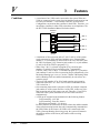
2.3.4
Extension Connection
Extension jacks 01 – 08 are for all kinds of telephones.
Telephone Wiring
The maximum length of the extension line cord (twisted cable)
which connects the system and the extension is as follows.
Diameter
of the line
Max. length
Single Line Telephone
22 AWG
1798 m {5900 feet}
(Station Loop Limit:
24 AWG
1128 m {3700 feet}
600 Ω including set)
26 AWG
698 m {2290 feet}
Proprietary Telephone
22 AWG
360 m {1180 feet}
(Station Loop Limit:
24 AWG
229 m {750 feet}
40 Ω)
26 AWG
140 m {460 feet}
2 or 4-conductor wiring is required for each extension as listed
below. There are four pins possible for connection: “T” (Tip),
“R” (Ring), “L” (Low) and “H” (High).
Telephone
Note
Wiring
Single line telephone
1 pair wire (T, R)
Proprietary telephone
(e.g., KX-T7030, KX-T7130)
2 pair wire (L, H, T, R)
• If a KX-TA62493 is installed;
Note the jack numbers for the facsimile and single line telephone which
have Caller ID service.
• If a telephone or answering machine with an A-A1 relay is connected to
the system, set the A-A1 relay switch on the telephone or answering
machine to the OFF position.
Connection
Insert the modular plugs of the telephone line cords (2 or 4conductor wiring) into the modular jacks on the system.
View of TEL Jack (Extension)
H: High
T: Tip
R: Ring
L: Low
H TR L
To extensions
(JACK 01–08)
ER
POW
2-12
Installation
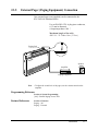
2.3.5
External Pager (Paging Equipment) Connection
One external pager (user-supplied) can be connected to the
KX-TA624 as illustrated below.
Use an EIAJ RC-6701 A plug (two-conductor,
ø 3.5 mm in diameter).
• Output impedance: 600 Ω
Maximum length of the cable
AWG 18 – 22: Under 10 m {33 feet}
Paging Jack
ER
POW
PAGING
Speaker
Amplifier
Paging Equipment
Note
• To adjust the sound level of the pager, use the volume control on the
amplifier.
Programming Reference
Section 4, System Programming
[106] External Paging Access Tone
Feature References
Section 3, Features
Paging – All
Paging – External
Installation
2-13
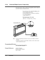
2.3.6
External Music Source Connection
One music source, such as a radio (user-supplied), can be connected
to the KX-TA624 as illustrated below.
Insert the plug to the earphone/headphone jack
on the external music source.
Use an EIAJ RC-6701 A plug (two-conductor,
ø 3.5 mm in diameter).
• Input impedance: 8 Ω
Maximum length of the cable
AWG 18 – 22: Under 10 m {33 feet}
External Music Jack
ER
POW
EXT.
MUSIC
External Music source
Note
• System programming for the music source used for Music on Hold is
required.
• To adjust the sound level of the Music on Hold, use the volume control
on the external music source.
Programming Reference
Section 4, System Programming
[111] Hold Music Selection
Feature References
2-14
Installation
Section 3, Features
Background Music (BGM)
Music on Hold
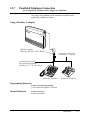
2.3.7
Paralleled Telephone Connection
(for a Proprietary Telephone and a Single Line Telephone)
Any single line telephone can be connected in parallel with a
proprietary telephone as follows.
Using a Modular T-Adaptor
Modular T-Adaptor
(Panasonic KX-J66 or USOC RJA2X)
2-conductor wiring cord
Connect pins “T” and “R”.
4-conductor wiring cord
For a proprietary telephone:
Connect pins “T”, “R”, “H” and “L”.
Proprietary Telephone
Single Line Telephone
Programming Reference
Section 4, System Programming
[610] Paralleled Telephone Connection
Feature Reference
Section 3, Features
Paralleled Telephone
Installation
2-15
2.3.8
Polarity Sensitive Telephone Connection
If the telephone is polarity sensitive, follow the procedure below:
1. Complete all the required extension
wiring.
2. Confirm that dialing can be done from all
the extensions using a touchtone
telephone.
If dialing fails, the polarity between the
extension and the system must be reversed.
Extension
Outside (CO) Line
3. Reverse as shown.
1
2
3
4
5
6
7
8
9
0
4. Unplug the system.
Reverse here
5. Connect all outside (CO) lines.
6. Confirm that dialing can be done on the
following extension using a touchtone
telephone.
Extension (T, R) of jack 01: Outside
(CO) line 1
If dialing fails, the polarity between the
system and the outside (CO) line must be
reversed.
7. Reverse as shown.
Extension
Outside (CO) Line
1
2
3
4
5
6
7
8
9
0
Reverse here
2-16
Installation
8. Every time an extension telephone is
replaced, repeat the procedure above.
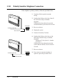
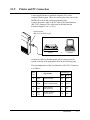
2.3.9
Printer and PC Connection
A user-supplied printer or personal computer (PC) can be
connected to the system. These are used to print out or refer to the
SMDR call records and system programming data.
Connect the printer cable or the PC cable to the Serial Interface
(RS-232C) connector. The cable must be shielded and the
maximum length is 2 m {6.5 feet}.
Serial Interface
(RS-232C) (D-SUB, 9-pin)
Printer
or
Computer
Arrange the cables so that the printer will be connected to the
system as shown in the appropriate chart on the following page.
The pin configuration of the Serial Interface (RS-232C) Connector
is as follows.
Circuit type
Pin
no.
Signal name
EIA
CCITT
2
RXD
Received Data
BB
104
3
4
TXD
DTR
Transmitted Data
Data Terminal Ready
BA
CD
103
108.2
5
6
SG
DSR
Signal Ground
Data Set Ready
AB
CC
102
107
7
8
RTS
CTS
Request To Send
Clear To Send
CA
CB
105
106
Installation
2-17
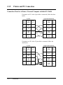
2.3.9
Printer and PC Connection
Connection Chart for a Printer / Personal Computer with the KX-TA624
If a printer or a PC with a 9-pin cable is connected, follow the chart
below.
System
9-pin Cable Printer/PC
Circuit
type
(EIA)
Signal
name
Pin
no.
Pin
no.
Signal
name
Circuit
type
(EIA)
BB
RXD
2
2
RXD
BB
BA
CD
TXD
DTR
3
4
3
4
TXD
DTR
BA
CD
AB
CC
SG
DSR
5
6
5
6
SG
DSR
AB
CC
CA
CB
RTS
CTS
7
8
7
8
RTS
CTS
CA
CB
If a printer or a PC with a 25-pin cable is connected, follow the
chart below.
System
2-18
Installation
25-pin Cable Printer/PC
Circuit
type
(EIA)
Signal
name
Pin
no.
Pin
no.
Signal
name
Circuit
type
(EIA)
BB
RXD
2
1
3
FG
RXD
AA
BB
BA
CD
TXD
DTR
3
4
2
TXD
BA
AB
CC
SG
DSR
5
6
20
7
DTR
SG
CD
AB
CA
CB
RTS
CTS
7
8
5
6
8
CTS
DSR
DCD
CB
CC
CF
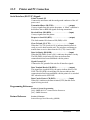
2.3.9
Printer and PC Connection
Serial Interface (RS-232C) Signals
Frame Ground: FG
Connects the unit frame and the earth ground conductor of the AC
power cord.
Transmitted Data: SD (TXD) . . . . . . . . . . . . . . . . (output)
Conveys signals from the unit to the printer. A “Mark” condition is
held unless data or BREAK signals are being transmitted.
Received Data: RD (RXD) . . . . . . . . . . . . . . . . . . . (input)
Conveys signals from the printer.
Request to Send: RS (RTS) . . . . . . . . . . . . . . . . . . (output)
This lead remains ON whenever DR (DSR) is ON.
Clear To Send: CS (CTS) . . . . . . . . . . . . . . . . . . . (input)
When the CS (CTS) circuit is ON, it indicates that the printer is
ready to receive data from the unit. The unit does not attempt to
transfer data or receive data when the CS (CTS) circuit is OFF.
Data Set Ready: DR (DSR) . . . . . . . . . . . . . . . . . . (input)
When the DR (DSR) circuit is ON, it indicates the printer is ready.
The DR (DSR) circuit being ON does not indicate that
communication has been established with the printer.
Signal Ground: SG
Connects the DC ground of the unit for all interface signals.
Data Terminal Ready: ER (DTR) . . . . . . . . . . . . . (output)
This signal line is turned ON by the unit to indicate that it is ON
LINE. The ER (DTR) circuit being ON does not indicate that
communication has been established with the printer. It is switched
OFF when the unit is OFF LINE.
Data Carrier Detect: CD (DCD) . . . . . . . . . . . . . . (input)
When ON, it indicates the data terminal (DTE) that the carrier
signal is being received.
Programming References
Section 4, System Programming
[800] SMDR RS-232C Communication Parameters
[801] SMDR Parameter
Feature Reference
Section 3, Features
Station Message Detail Recording (SMDR)
Installation
2-19
2.4
2.4.1
Installation of Optional Cards
Location of Optional Cards
The location of the optional cards is shown below.
Precaution To protect the printed circuit boards (P-boards) from static electricity, do
not touch parts on the P-boards in the main unit and on the optional
cards. If accessing the part is required, wear a grounding strap.
3 CO Line and 8 EXT
Expansion Card
(KX-TA62477) or
8 Extension Expansion
Card (KX-TA62470)
Connector
Doorphone/Door Opener Card
(KX-TA62460) Connector
The front covers are open.
OGM/FAX Detection Card (KX-TA62491)
Connector
Caller ID Card (KX-TA62493)
Connector
Note:
Power off the System, and unplug the AC cord before installing an optional card.
2-20
Installation
2.4.2
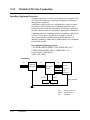
Caller ID and OGM/FAX Detection Card Installation
A Caller ID Card (KX-TA62493) and OGM/FAX Detection Card
(KX-TA62491) can be installed to the system.
The Caller ID Card supports the following.
Caller ID: Receives the Caller ID Service from the Central Office.
A display proprietary telephone with Caller ID service can
display the information. It can also display caller’s information
which has been stored in the system according to the Caller ID
service.
The OGM/FAX Detection Card supports the following.
Direct Inward System Access (DISA) with an OGM:
One of the system features. An outgoing message greets the
external caller and gives information so that the caller can
access the extension(s) directly.
Facsimile detection:
When the system receives a facsimile transmission signal by
DISA, it automatically connects the specified facsimile
extension.
1. Remove the two screws.
Screws
2. Open the bottom front cover.
Bottom front cover
Installation
2-21
2.4.2
Caller ID and OGM/FAX Detection Card Installation
3. Attach the optional cards.
Caller ID Card
(KX-TA62493)
OGM/FAX Detection Card
(KX-TA62491)
Install the Caller ID Card for
the KX-TA62477 here.
Note
Please do not damage this part.
4. Insert the flat cables to each card connector.
Flat cables
5. Close the cover.
Condition
• Be sure the frame of the main unit is connected to the ground. Refer
to Section 2.2.4 “Frame Ground Connection”.
Programming Reference
See “Programming References” in Section 3, Features, Caller ID and
Direct Inward System Access (DISA).
Feature References
2-22
Installation
Section 3, Features
Caller ID
Direct Inward System Access (DISA)
Outgoing Message (OGM)
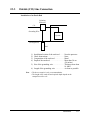
2.4.3
Doorphone and Door Opener Connection
Four doorphones (KX-T30865) and four door openers (usersupplied) can be installed.
Maximum cable length
The maximum length of the doorphone and door opener line cord
which connects the system is as follows.
Diameter of the line
Max. length
Doorphone
22 AWG
180 m {590 feet}
(Station Loop
24 AWG
113 m {370 feet}
Limit: 20 Ω)
26 AWG
70 m {230 feet}
Door Opener
22 AWG
180 m {590 feet}
Installing the Doorphone
1. Loosen the screw to open the doorphone unit.
ic
ason
Pan
Screw
2. Attach the base cover to a wall using two screws.
Screws
Note
Two kinds of screws are included. Please choose the
appropriate one depending on your type of wall.
Type 1: When a doorphone plate has been
fixed to the wall.
Type 2: When you wish to install the
doorphone directly to the wall.
3. Connect the wires to the screws located in the front cover.
To the terminal box
4. Put the doorphone together and re-install the screw.
Installation
2-23
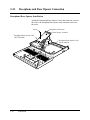
2.4.3
Doorphone and Door Opener Connection
Doorphone/Door Opener Installation
Attach the Doorphone/Door Opener Card to the main unit, connect
the cord to the doorphone/door opener card connector and secure
the screw.
Screw
Doorphone Connectors
Door Opener Terminal
Doorphone/Door Opener Card
(KX-TA62460)
Doorphone/Door Opener Card
Card Connector
2-24
Installation
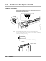
2.4.3
Doorphone and Door Opener Connection
Wiring of the Doorphone
1. Connect the Doorphone/Door Opener Card to the terminal
boxes using 4-conductor modular connectors.
2. Connect the wires of doorphones 1 and 3 to the red and green
screws on the terminal box.
3. Connect the wires of doorphones 2 and 4 to the yellow and
black screws on the terminal box.
View of Doorphone Connector Jack
Doorphone 2
Doorphone 4
Doorphone 1
Doorphone 3
4-conductor wiring
is required.
Yellow
Red
Black
Green
Panasonic
Panasonic
Doorphone 1
(KX-T30865)
Doorphone 2
(KX-T30865)
4-conductor wiring
is required.
Yellow
Red
Black
Green
Panasonic
Doorphone 3
(KX-T30865)
Panasonic
Doorphone 4
(KX-T30865)
Installation
2-25
2.4.3
Doorphone and Door Opener Connection
Connecting Door Openers
While pressing the button below a hole with a driver, insert the wire
from the door opener into the hole.
Door opener 1
Door opener 4
Door opener 2
Door opener 3
Note
• We recommend using UL1015 wire or the equivalent for wiring.
• The wire should be between 0.4 mm and 1.2 mm {1/64 inch – 3/64 inch}
in diameter including the coating.
D = 0.4 mm – 1.2 mm {1/64 inch – 3/64 inch}
To the door openers
2-26
Installation
2.4.3
Doorphone and Door Opener Connection
Programming References
Section 4, System Programming
[700]–[702] Doorphone Ringing Assignment — Day/Night/Lunch
[703]–[705] Door Opener Assignment — Day/Night/Lunch
Feature References
Section 3, Features
Door Opener
Doorphone Call
Installation
2-27
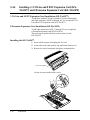
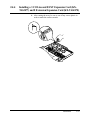
2.4.4
Installing a 3 CO Line and 8 EXT Expansion Card (KXTA62477) and 8 Extension Expansion Card (KX-TA62470)
3 CO Line and 8 EXT Expansion Card Installation (KX-TA62477)
To add three outside (CO) lines (outside (CO) lines 4 through 6)
and eight extensions (JACK 09 through 16), use an optional 3 CO
Line and 8 EXT Expansion card (KX-TA62477).
8 Extension Expansion Card Installation (KX-TA62470)
To add eight extensions (JACK 17 through 24), use an optional
8 Extension Expansion card (KX-TA62470).
This card can be installed directly to the system or to the
KX-TA62477.
Installing the KX-TA62477
1. Power off the system, and unplug the AC cord.
2. Loosen the screws and open the top and bottom front covers.
3. Remove the lower front panel with pliers as shown below.
Lower front panel
Cut the six areas marked with a circle.
2-28
Installation
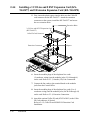
2.4.4
Installing a 3 CO Line and 8 EXT Expansion Card (KXTA62477) and 8 Extension Expansion Card (KX-TA62470)
4. After cutting the areas, be sure to cut off any excess plastic in
order to make the surface smooth.
Installation
2-29
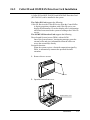
2.4.4
Installing a 3 CO Line and 8 EXT Expansion Card (KXTA62477) and 8 Extension Expansion Card (KX-TA62470)
5. First, insert the plastic spacer into the hole near the Caller ID
card connector on the KX-TA62477. Attach the extension
connectors to the system, install the KX-TA62477 and secure
the two extension bolts.
Extension Bolts
3 CO Line and 8 EXT Expansion Card
(KX-TA62477)
Caller ID Card Connector
Extension Connectors
Spacer
6. Insert the modular plugs of the telephone line cords
(2-conductor wiring) into the modular jacks (CO 4 through 6)
on the card. Refer to 2.3.3, Outside (CO) Line Connection.
7. Connect the line cords to the terminal board or the modular
jacks from the Central Office.
8. Insert the modular plugs of the telephone line cords (2 or 4conductor wiring) into the modular jacks (JACK 09 through 16)
on the card. Refer to 2.3.4, Extension Connection.
9. Attach the optional Caller ID card (KX-TA62493) to the Caller
ID Card connector, if desired.
Refer to 2.4.2, Caller ID and OGM/FAX Detection Card
Installation.
2-30
Installation
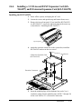
2.4.4
Installing a 3 CO Line and 8 EXT Expansion Card (KXTA62477) and 8 Extension Expansion Card (KX-TA62470)
Installing the KX-TA62470
1. Power off the system, and unplug the AC cord.
2. Loosen the screws and open the top and bottom front covers.
3. Remove the lower front panel. If you install the KX-TA62470
to a KX-TA62477, remove the top front panel in the same way
as described in “ Installing the KX-TA62477”.
Top front panel
4. Attach the extension connectors to the system first, install the
KX-TA62470 and secure the two screws.
Screws
8 Extension Expansion Card
(KX-TA62470)
Extension Connectors
5. Insert the modular plugs of the telephone line cords (2 or 4conductor wiring) into the modular jacks (JACK 17 through 24)
on the card. Refer to 2.3.4, Extension Connection.
Installation
2-31
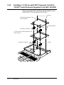
2.4.4
Installing a 3 CO Line and 8 EXT Expansion Card (KXTA62477) and 8 Extension Expansion Card (KX-TA62470)
When you install the KX-TA62470 to the KX-TA62477, install
the KX-TA62477 first and then the KX-TA62470.
Screws
8 Extension Expansion Card
(KX-TA62470)
Extension Bolts
Extension Connectors
3 CO Line and 8 EXT Expansion Card
(KX-TA62477)
Extension Connectors
2-32
Installation
Spacer
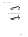
2.4.5
Securing the cords
1. Wrap the strap around all of the cords.
2. Close the covers and secure the screws.
Note
• To remove the strap, loosen the rivet with a driver.
Rivet
Installation
2-33
2.5
Auxiliary Connection for Power Failure
Transfer
Power failure transfer connects a specific single line telephone to
selected outside (CO) lines in the event of system power failure, as
follows.
Outside (CO) Line 1 – Extension (T, R) Jack 01
Outside (CO) Line 4 – Extension (T, R) Jack 09
Connection of outside (CO) lines 1 and 4, and the respective
extensions require no auxiliary connection.
Note
Feature References
2-34
Installation
• In the event of a power failure, system memory is protected by a factoryprovided lithium battery. There is no memory loss except the Camp-on,
Saved Number Redial, Last Number Redial, Call Park and Message
Waiting memories.
• The system automatically changes the current connection to the above
connection when the power supply stops.
• Proprietary telephones cannot be used during a system power failure.
Therefore, we recommend connecting single line telephones in parallel
with the proprietary telephones connected to JACK 01 and 09.
Section 3, Features
Paralleled Telephone
Power Failure Transfer
2.6
Closing the Front Cover
1. Replace the covers and tighten the screws.
2. Tie together all of the connected cords and attach them to the
wall so that the cords cannot be pulled out of the system.
Installation
2-35
2.7
Starting the System for the First Time
1. Plug the AC power cord into the system and an AC outlet.
2. Turn the Power Switch on. (The power indicator will light.)
3. Perform the following operation with a proprietary telephone
connected to JACK 01.
a) Set the MEMORY switch on the telephone to
“PROGRAM”.
b) Dial £#.
c) Enter the system password, 1234.
d) Enter 999.
e) Press NEXT (SP-PHONE button).
f) Keep pressing SELECT (AUTO ANSWER/MUTE button)
until “All Para” is displayed.
g) Press STORE (AUTO DIAL/STORE button).
h) Press END (HOLD button).
i) Set the MEMORY switch to “SET”.
The system will be initialized with the default values. If the system
does not work properly, see “2.9, System Data Clear”.
CAUTION
• The system will continue to be powered even if the Power Switch is
turned “OFF”.
• The power supply cord is used as the main disconnect device. Ensure
that the outlet is located/installed near the equipment and is easily
accessible.
Notice
When leaving the product unused for a
long time, turn off the Power Switch of
the unit and remove the AC power cord
from the wall socket for power saving.
AC Surge Protector
134 cm (52 1/16 inches)
2-36
Installation
2.8
System Restart
After starting the system, if the system does not operate properly,
restart the system.
Before restarting the system, try the system feature again to confirm
whether there definitely is a problem or not.
System Restart causes the following.
1. Camp-on is cleared.
2. Calls on Hold are terminated.
3. Calls on Exclusive Hold are terminated.
4. Calls in progress are terminated.
5. Call Park is cleared.
6. Last Number Redial is cleared.
7. Saved Number Redial is cleared.
8. Message Waiting is cleared.
Other data is not cleared by System Restart.
1. Turn the Power switch off and then on.
Notice
If the system still does not operate properly, please see Section 2.9,
“System Data Clear”.
Installation
2-37
2.9
System Data Clear
When the system does not operate properly after restarting, you can
clear the programming data stored in the system. The system will
restart with the default settings. First, try system program [999]. If
the system still does not operate properly, please follow the
procedure below.
1. Loosen the screws and open the top and bottom front covers.
2. Slide the System Clear Switch to the “CLEAR” position.
3. Press the Reset Button.
4. Return the System Clear Switch to the “NORMAL” position
before the power indicator stops flashing.
(The power indicator will flash for about 10 seconds.)
Reset Button
CLEAR/NORMAL
System Clear Switch
CAUTION
Notice
Before touching the System Clear Switch and Reset Button, put on a
grounding strap.
After pressing the Reset Button, return the System Clear Switch to the
“NORMAL” position in step 4 before the power indicator stops flashing.
Otherwise, the system will not clear.
Programming Reference
Section 4, System Programming
[999] System Data Clear
2-38
Installation
Section 3
Features
This section describes every basic, optional, and
programmable feature in alphabetical order. It also provides
information about the conditions, connection references,
programming required, related features, and operation
for every feature.
A
3
Features
Absent Message Capability
Description
Allows an extension user to set a message which will be displayed
at the calling extension to show the reason for the called extension’s
absence. Six messages can be programmed as desired, which are
available for every extension user. Setting or canceling a message
can be done by individual extension users but only callers with a
display telephone can view the message.
Conditions
• The six messages are shown below. “%” means a parameter to be
entered when assigning a message at an extension.
(1) Will Return Soon
(2) Gone Home
(3) At Ext %%% (extension number)
(4) Back at %% : %% AM (or PM) (hour : minute)
(5) Out Until %% / %% (month / day)
(6) In a Meeting
• An extension user can only select one message at a time. The selected
message is displayed every time the user goes off-hook.
Programming References
No programming required.
Feature References
None
Operation Reference
— User Manual
Telephone Features
Absent Message Capability
3-2
Features
3
A
Features
Account Code Entry
Description
An Account Code is used to identify incoming and outgoing outside
calls for accounting and billing purposes. The account code is
appended to the Station Message Detail Recording (SMDR) call
record. For incoming outside calls, account codes are optional. For
outgoing outside calls, there are four modes available to enter an
account code: Verify-All mode, Verify-Toll mode, Forced mode, and
Option mode. One mode is selected for each extension.
In Verify-All mode, the user must always enter a pre-assigned
account code when making any of the following calls unless it has
previously been stored in memory.
• Call Forwarding – to Outside (CO) Line
• Last Number Redial
• Line Access
• One-Touch Dialing
• Personal Speed Dialing
• Pickup Dialing
• Saved Number Redial
• System Speed Dialing
In Verify-Toll mode, the user can enter a pre-assigned account code
only when the user needs to override toll restriction. Calls with COS
numbers 3 through 5 will be treated as calls with COS number 2.
Calls with COS numbers 1 and 2 will not be affected.
In Forced mode, the user must always enter an account code. The
code can be any number.
In Option mode, the user can enter any account code if needed.
Conditions
• An account code can be stored into Memory Dialing (System/Personal
Speed Dialing, One-Touch Dialing, Pickup Dialing, Call Forwarding – to
Outside (CO) Line).
• Account code entry after CPC detection must be done within 30 seconds.
Otherwise, the SMDR call record is activated and the code cannot be
entered.
• In any mode, emergency dial numbers stored in program
[309] “Emergency Dial Number Set” can be dialed out without an
account code entry.
Programming References
Feature Reference
Operation Reference
— User Manual
Section 4, System Programming
[310] Account Codes
[601]–[603] TRS – Class of Service (COS) Assignment
— Day/Night /Lunch
[605] Account Code Entry Mode
[805] SMDR Account Code Selection
Section 3, Features
Toll Restriction Override by Account Codes
Telephone Features
Account Code Entry
Features
3-3
A
3
Features
Answering, Direct Outside (CO) Line
Description
Allows a proprietary telephone user to answer an incoming call by
simply pressing the appropriate CO button without lifting the
handset or pressing the SP-PHONE/MONITOR button.
Condition
• This feature allows the user to specify which line will be answered when
multiple incoming lines are ringing.
Programming References
No programming required.
Feature Reference
Section 3, Features
Outside (CO) Line Connection Assignment
Operation Reference
— User Manual
Telephone Features
Answering, Direct Outside (CO) Line
3-4
Features
3
A
Features
Automatic Callback Busy (Camp-On)
Description
Allows the caller to be notified when the called party or selected
outside (CO) line becomes free.
Automatic Callback – Extension
If the caller answers the callback ringing (Camp-On Recall), the
called extension will automatically start ringing.
Automatic Callback – Outside (CO) Line
If the caller answers the callback ringing (Camp-On Recall), the
line will be automatically selected to allow the user to make an
outside call.
Conditions
• If the callback ringing (Camp-On Recall) is not answered in four rings
(within 10 seconds), the callback will be canceled.
• More than one extension user can set this function to one extension or
outside (CO) line at the same time.
Programming References
No programming required.
Feature References
None
Operation Reference
— User Manual
Telephone Features
Automatic Callback Busy (Camp-On)
Features
3-5
B
3
Features
Background Music (BGM)
Description
Allows a proprietary telephone user to listen to background music
from the speaker monitor on their telephone.
Conditions
• A user-supplied external music source, such as a radio, must be
connected. One external music source can be connected to the system.
• The music source is used for BGM and/or Music on Hold.
• The music is interrupted when you go off-hook.
Connection Reference
Section 2, Installation
2.3.6 External Music Source Connection
Programming References
No programming required.
Feature Reference
Section 3, Features
Music on Hold
Operation Reference
— User Manual
Telephone Features
Background Music (BGM)
3-6
Features
3
B
Features
Busy Lamp Field
Description
The LED (Light Emitting Diode) indicators of the DSS (Direct
Station Selection) buttons, corresponding to selected extensions,
show whether the extensions are idle or busy.
Conditions
• This function is available for flexible CO buttons assigned as DSS
buttons on proprietary telephones and DSS buttons on DSS Consoles.
• A DSS button indicator lights red if the corresponding extension is busy.
Programming Reference
Station Programming . . . . . . . . . . . . . . . . . . . . User Manual
Flexible Button Assignment – Direct Station Selection (DSS) Button
Feature Reference
Section 3, Features
Button, Direct Station Selection (DSS)
Operation References
Not applicable.
Busy Station Signaling (BSS)
Description
When attempting to call a busy extension, Busy Station Signaling
allows you to signal the extension to answer your call. The called
extension user hears a Call Waiting tone and then is able to answer
the call.
Condition
• This feature only works if the called extension has activated Call
Waiting. If Call Waiting is activated, the caller will hear a ringback tone.
If not, the caller will hear a reorder tone.
Programming References
No programming required.
Feature Reference
Section 3, Features
Call Waiting
Operation Reference
— User Manual
Telephone Features
Busy Station Signaling (BSS)
Features
3-7
B
3
Features
Button, Direct Station Selection (DSS)
Description
A DSS button allows a proprietary telephone user one-touch access
to other extension users.
Conditions
• A flexible CO button and MESSAGE button on a proprietary telephone
can be assigned as a DSS button using station programming.
• DSS buttons are provided on DSS Consoles with a default setting.
Changing the setting is possible from a paired telephone using station
programming.
• Once a button is assigned as a DSS button, the Busy Lamp Field (BLF)
status is available.
• The mode of a DSS button can be programmed to disconnect the outside
(CO) line and call the extension, or hold and transfer the call to the
extension (One-Touch Transfer Using a DSS Button).
Programming References
Section 4, System Programming
[005] One-Touch Transfer Using a DSS Button
Station Programming . . . . . . . . . . . . . . . . . . . . User Manual
Flexible Button Assignment – Direct Station Selection (DSS) Button
DSS Console Features . . . . . . . . . . . . . . . . . . . User Manual
Station Programming
Feature References
Section 3, Features
Busy Lamp Field
DSS Console (KX-T7040)
One-Touch Transfer Using a DSS Button
Operation References
— User Manual
Basic Operations
Making Calls
Telephone Features
Call Transfer – to Extension
DSS Console Features
3-8
Features
3
B
Features
Button, Flexible
Description
The use of Flexible Buttons is determined by station programming.
The following four types of Flexible Buttons are provided on
proprietary telephones (PT) and DSS Consoles:
• Flexible CO buttons (provided on a PT only)
• Flexible Direct Station Selection (DSS) buttons (provided on a
DSS Console only)
• MESSAGE button (provided on a PT except for the KX-T7055)
• Programmable Feature (PF) buttons
The table below shows all of the features which can be assigned to
Flexible Buttons.
Button
Features to be assigned
Group-CO
Other-CO
Single-CO
Caller ID Indication — Common
Caller ID Indication — Personal
Caller ID Selection — Common
Caller ID Selection — Personal
Conference
FWD/DND
Log-In/Log-Out
Saved Number Redial
Day
Lunch
Night
Station Lock
Message Waiting
Another Extension Message
Waiting
Live Call Screening (LCS)†
LCS Cancel†
Two-Way Record†
Two-Way Transfer†
Voice Mail Transfer†
Direct Station Selection (DSS)
One-Touch Dialing
CO
(PT)
✔
✔
✔
✔
✔
✔
✔
✔
✔
✔
✔
DSS
PF
MESSAGE
(DSS) (PT/DSS)
✔
✔
✔
✔
✔
✔
✔
✔
✔
✔
✔
✔
✔
✔
✔
✔
✔
✔
✔
✔
✔
✔
✔
✔
“✔” indicates that the feature is available.
† Available when the KX-TA624 is connected to a Proprietary Telephone capable Panasonic
Voice Processing System (one that supports APT Integration; KX-TVS50/KX-TVS80).
Features
3-9
B
3
Condition
Features
• Incoming and outgoing calls on a line are shown in the following
priority.
Single-CO > Group-CO
Programming References
Station Programming . . . . . . . . . . . . . . . . . . . . User Manual
Flexible Button Assignment
DSS Console Features (KX-T7040) . . . . . . . . . User Manual
Feature References
Section 3, Features
Buttons on Proprietary Telephones
DSS Console (KX-T7040)
Operation References
Not applicable.
3-10
Features
3
B
Features
Button, Group-CO (G-CO)
Description
To support efficient utilization of outside (CO) lines, a group of
outside (CO) lines (outside (CO) line group) can be assigned to a
CO button. The function is referred to as Group-CO (G-CO). Any
incoming call from any outside (CO) line in the outside (CO) line
group arrives at the G-CO button. To make an outside call, the user
can access an idle outside (CO) line in the group by simply pressing
the assigned G-CO button.
Conditions
• A G-CO button is not originally provided on a proprietary telephone
(PT). It can be programmed on a CO button by station programming.
• The extension for receiving and/or originating calls on outside (CO)
lines must be programmed.
• The same outside (CO) line group can be assigned to more than one GCO button on the same PT.
• The same line can be assigned to a Single-CO (S-CO) button and a
G-CO button.
• Immediate, delayed, no ringing or no incoming call (disable) can be
selected on an extension-outside (CO) line basis.
• Users can choose a desired ringing pattern for each outside (CO) line by
system programming.
Programming References
Section 4, System Programming
[400] Outside (CO) Line Connection Assignment
[404] Outside (CO) Line Group Assignment
[405]–[407] Flexible Outward Dialing Assignment — Day/Night/Lunch
[408]–[410] Flexible Ringing Assignment — Day/Night/Lunch
[411]–[413] Delayed Ringing Assignment — Day/Night/Lunch
[423] Outside (CO) Line Ringing Pattern Selection
Station Programming . . . . . . . . . . . . . . . . . . . . User Manual
Flexible Button Assignment – Group-CO (G-CO) Button
Feature References
Operation References
— User Manual
Section 3, Features
Answering, Direct Outside (CO) Line
LED Indication, Outside (CO) Line
Line Access, Outside (CO) Line Group
Outside (CO) Line Group
Ringing, Delayed
Ringing Pattern Selection for
Intercom Calls and Outside
(CO) Lines
Basic Operations
Making Calls
Receiving Calls
Telephone Features
Answering, Direct Outside (CO) Line
Outward Dialing – Line Access, Automatic, Outside (CO) Line Group
Features
3-11
B
3
Features
Button, Other-CO (O-CO)
Description
Outside (CO) lines, which are not assigned to a S-CO or G-CO
button, can be assigned to a flexible CO button on a proprietary
telephone (PT). The assigned button serves as the Other-CO
(O-CO) button. An incoming call on an outside (CO) line arrives at
the O-CO. To make an outside call, the PT user simply presses the
assigned O-CO button.
Conditions
• An O-CO button is not originally provided on a PT. A flexible CO
button can be assigned as an O-CO button by station programming.
• Immediate, delayed, no ringing or no incoming call (disable) can be
selected on an extension – outside (CO) line basis.
• Users can choose a desired ringing pattern for each outside (CO) line by
system programming.
Programming References
Section 4, System Programming
[400] Outside (CO) Line Connection Assignment
[404] Outside (CO) Line Group Assignment
[405]–[407] Flexible Outward Dialing Assignment — Day/Night/Lunch
[408]–[410] Flexible Ringing Assignment — Day/Night/Lunch
[411]–[413] Delayed Ringing Assignment — Day/Night/Lunch
[423] Outside (CO) Line Ringing Pattern Selection
Station Programming . . . . . . . . . . . . . . . . . . . . User Manual
Flexible Button Assignment – Other-CO (O-CO) Button
Feature References
Operation References
— User Manual
3-12
Features
Section 3, Features
Answering, Direct Outside (CO) Line
LED Indication, Outside (CO) Line
Line Access, Automatic
Line Access, Direct
Ringing, Delayed
Ringing Pattern Selection for
Intercom Calls and Outside
(CO) Lines
Basic Operations
Making Calls
Receiving Calls
Telephone Features
Outward Dialing – Line Access, Automatic
3
B
Features
Button, Single-CO (S-CO)
Description
A Single-CO (S-CO) button is an outside (CO) line access button.
This allows a proprietary telephone user to access a specific line by
pressing a S-CO button. An incoming call can be directed to a
S-CO button.
Conditions
• The default setting for CO buttons is changeable. (Flexible CO Button)
• A S-CO button provides outside (CO) line status.
• One outside (CO) line can be assigned to both a S-CO and a Group-CO
(G-CO) button.
• Incoming calls are indicated on a proprietary telephone, when an
extension is assigned as the incoming call destination and a S-CO,
G-CO and/or O-CO button is assigned.
• Immediate, delayed, no ringing or no incoming call (disable) can be
selected on an extension–outside (CO) line basis.
• Users can choose a desired ringing pattern for each outside (CO) line by
system programming.
Programming References
Section 4, System Programming
[400] Outside (CO) Line Connection Assignment
[404] Outside (CO) Line Group Assignment
[405]–[407] Flexible Outward Dialing Assignment — Day/Night/Lunch
[408]–[410] Flexible Ringing Assignment — Day/Night/Lunch
[411]–[413] Delayed Ringing Assignment — Day/Night/Lunch
[423] Outside (CO) Line Ringing Pattern Selection
Station Programming . . . . . . . . . . . . . . . . . . . . User Manual
Flexible Button Assignment – Single-CO (S-CO) Button
Feature References
Operation References
— User Manual
Section 3, Features
Answering, Direct Outside (CO) Line
LED Indication, Outside (CO) Line
Line Access, Direct
Line Access, Individual
Ringing, Delayed
Ringing Pattern Selection for
Intercom Calls and Outside
(CO) Lines
Basic Operations
Making Calls
Receiving Calls
Telephone Features
Outward Dialing – Line Access, Individual
Features
3-13
B
3
Features
Buttons on Proprietary Telephones
Description
Proprietary telephones are provided with the feature/line access
buttons listed below.
KX-T Proprietary Telephones
Buttons
7020 7030 7050 7055 7130 7135
AUTO ANSWER/MUTE❖
✔
✔
AUTO DIAL/STORE❖
✔
✔
CO❖*
✔
✔!
✔
✔
✔
✔
✔(12) ✔(12) ✔(12) ✔(3) ✔(12) ✔(12)
CONF❖
✔
✔
✔!
✔!
✔
✔
FLASH
✔
✔
✔
✔
✔
✔
FWD/DND❖
✔
✔
✔
✔
HOLD
✔
✔
✔
✔
✔
✔
INTERCOM❖
✔
✔
✔
✔
✔
✔
MESSAGE❖*
✔
✔
✔
✔
✔
✔
✔
MONITOR❖
PAUSE
✔
✔
✔
✔!
✔
✔
PF (Programmable Feature) ✔(4) ✔(4) ✔(4) ✔(3) ✔(12) ✔(12)
REDIAL
✔
✔
✔
✔
SAVE
SP-PHONE❖
✔
✔
TRANSFER
✔
✔
✔
✔
✔
✔
✔
✔
✔
✔
✔
✔
✔: The button is provided on the designated telephone.
❖: The button has a LED (Light Emitting Diode).
* : Buttons which can be changed to function as a feature button are called
flexible buttons.
!: The button does not have a LED.
(x): Shows the number of buttons only if more than one button is provided.
3-14
Features
3
B
Features
The functions of the listed buttons are described below.
AUTO ANSWER/MUTE: Used for answering an extension
automatically, or turns the microphone off during a conversation.
AUTO DIAL/STORE: Used for System Speed Dialing and storing
program changes.
CO (Central Office line): Can make or receive an outside call or
can be re-assigned to a different CO or various feature buttons.
CONF (Conference): Used to establish a three-party conference.
FLASH: Allows you to disconnect the current call and originate
another call without hanging up (Flash). Sends a flash signal to the
Central Office or host PBX to access their features (External
Feature Access).
FWD/DND (Call Forwarding/Do Not Disturb): Used to program
Call Forwarding, and set Do Not Disturb.
HOLD: Used to place a call on hold.
INTERCOM: Used to make or receive intercom calls.
MESSAGE: Used to send a message, display the current message,
call back the message sender, or can be assigned as another feature
button.
MONITOR: Used for a hands-free operation.
PAUSE: Inserts a pause in a speed dial number.
PF (Programmable Feature): This flexible button can be
programmed as a One-Touch Dialing button, if desired.
REDIAL: Used for Last Number or Automatic Redialing.
SAVE: Used to store a dialed telephone number for Saved Number
Redial.
SP-PHONE (Speakerphone): Used for a hands-free speakerphone
operation. Pressing the button causes the telephone to switch
between the handset and hands-free operation.
TRANSFER: Transfers a call to another extension or external
destination.
Conditions
• Certain buttons are equipped with light indicators (LED’s) to show the
line or feature status.
• CO buttons can be classified according to the following three types:
Single-CO (S-CO) button / Group-CO (G- CO) button /
Other-CO (O- CO) button
Programming Reference
Station Programming . . . . . . . . . . . . . . . . . . . . User Manual
Flexible Button Assignment
Feature References
None
Operation References
— User Manual
Refer to the appropriate operating instructions.
Features
3-15
C
3
Features
CALL FORWARDING FEATURES – SUMMARY
Description
Call Forwarding features enable an extension user to have their
calls forwarded to a specified destination. The user may determine
the conditions of how their calls will be forwarded. The following
Call Forwarding features are available:
Call Forwarding – All Calls
Call Forwarding – Busy/No Answer
Call Forwarding – Follow Me
Call Forwarding – to an Outside (CO) Line
Call Forwarding – All Calls
Description
This feature is used when a user wants all their calls to be
automatically re-directed to another extension.
Conditions
• The types of calls which are forwarded by this feature are:
Outside calls – DIL; DISA; Normal
Intercom calls – Extension; Transfer
• The extensions which have already been assigned as a forwarded
destination cannot set the Call Forwarding feature.
• Although calls can be forwarded, Message Waiting cannot. The
MESSAGE button indicator will light on the original called extension.
• If the Do Not Disturb (DND) feature has already been set, setting the
Call Forwarding feature will cancel DND.
• System Programming determines which extensions are able to perform
this feature for certain outside calls.
Programming References
Section 4, System Programming
[963] Call Forwarding Selection
Station Programming . . . . . . . . . . . . . . . . . . . . User Manual
Flexible Button Assignment – FWD/DND Button
Feature References
None
Operation Reference
— User Manual
Telephone Features
Call Forwarding — All Calls
3-16
Features
3
C
Features
Call Forwarding – Busy/No Answer
Description
A user’s calls are forwarded to another extension if their extension
is busy or they do not answer the call within a pre-determined time.
Conditions
• The types of calls which are forwarded by this feature are:
Outside calls – DIL; DISA; Normal
Intercom calls – Extension; Transfer
• The extensions which have been already assigned as the forwarded
destination cannot set the Call Forwarding feature.
• Although calls can be forwarded, Message Waiting cannot. The
MESSAGE button indicator will light on the original called extension.
• If the Do Not Disturb (DND) feature has already been set, setting the
Call Forwarding feature will cancel DND.
• System Programming determines which extensions are able to perform
this feature for certain outside calls.
Programming References
Section 4, System Programming
[202] Call Forwarding Start Time
[963] Call Forwarding Selection
Station Programming . . . . . . . . . . . . . . . . . . . . User Manual
Flexible Button Assignment – FWD/DND Button
Feature References
None
Operation Reference
— User Manual
Telephone Features
Call Forwarding — Busy/No Answer
Features
3-17
C
3
Features
Call Forwarding – Follow Me
Description
If a user forgets to set Call Forwarding – All Calls before they leave
their desk, this allows them to set the same feature from the
destination extension.
Condition
• Same as the conditions for Call Forwarding – All Calls.
• System Programming determines which extensions are able to perform
this feature for certain outside calls.
Programming References
Section 4, System Programming
[963] Call Forwarding Selection
Station Programming . . . . . . . . . . . . . . . . . . . . User Manual
Flexible Button Assignment – FWD/DND Button
Feature Reference
Section 3, Features
Call Forwarding – All Calls
Operation Reference
— User Manual
Telephone Features
Call Forwarding — Follow Me
3-18
Features
3
C
Features
Call Forwarding – to an Outside (CO) Line
Description
Calls directed to an extension will be sent to an external destination.
The outside telephone number must be pre-programmed.
Conditions
• The types of calls which are forwarded by this feature are:
Outside calls – DIL; DISA
Intercom calls – Extension; Transfer
• The forwarding extension’s Toll Restriction and Account Code Entry
requirements still apply.
• If the Do Not Disturb (DND) feature has already been set, setting the
Call Forwarding feature will cancel DND.
• System programming determines which extensions are able to perform
this feature.
• If a call between two outside parties is established by this feature, the
duration of the call is determined by the system timer. An alarm tone is
generated to both outside parties 15 seconds before the time-out. The
call is disconnected at the time-out.
Programming References
Section 4, System Programming
[205] Outside-to-Outside (CO-to-CO) Line Duration Time Limit
[607] Call Forwarding to an Outside (CO) Line
Station Programming . . . . . . . . . . . . . . . . . . . . User Manual
Flexible Button Assignment – FWD/DND Button
Feature Reference
Section 3, Features
Limited Call Duration
Operation Reference
— User Manual
Telephone Features
Call Forwarding — to an Outside (CO) Line
Features
3-19
C
3
Features
Call Hold – Intercom
Description
This is used to place an intercom call on hold. The held call can be
retrieved by the user who held it or by any other extension.
Conditions
• Only one intercom call can be placed on hold (up to ten calls in the
system – Call Park). With a proprietary telephone, outside calls and one
intercom call can be placed on hold at the same time. With a single line
telephone, either one outside or intercom call can be held.
• If a call on hold is not retrieved within a pre-assigned period of time,
Hold Alarm/Hold Recall occurs.
Programming References
Section 4, System Programming
[104] Hold Mode Selection
[200] Hold Recall Time
Feature References
Section 3, Features
Call Park
Hold Alarm/Hold Recall
Operation Reference
— User Manual
Telephone Features
Call Hold
3-20
Features
3
C
Features
Call Hold – Outside (CO) Line
Description
Allows an extension user to put an outside call on hold. The held
call can be retrieved by the user who held it or by any other
extension.
Conditions
• With a single line telephone, the user can hold only one call, either an
extension or outside call.
• Music is sent to the party on hold, if available (Music on Hold).
• If a call on hold is not retrieved within a specific period of time, Hold
Alarm/Hold Recall occurs.
• If an external party is placed on hold and not retrieved within 30
minutes, it will be automatically disconnected.
Programming References
Section 4, System Programming
[104] Hold Mode Selection
[200] Hold Recall Time
Feature References
Section 3, Features
Hold Alarm/Hold Recall
Music on Hold
Operation Reference
— User Manual
Telephone Features
Call Hold
Features
3-21
C
3
Features
Call Hold, Exclusive – Intercom
Description
Allows a proprietary telephone user to prevent other extension users
from retrieving a held intercom call. Only the user who held the call
can retrieve it.
Conditions
• Only one intercom call can be placed on Call Hold or Exclusive Call
Hold at a time.
• If a call on hold is not retrieved within a pre-assigned period of time,
Hold Alarm/Hold Recall occurs.
• This feature is not available for single line telephones.
Programming Reference
Section 4, System Programming
[200] Hold Recall Time
Feature Reference
Section 3, Features
Hold Alarm/Hold Recall
Operation Reference
— User Manual
Telephone Features
Call Hold, Exclusive
Call Hold, Exclusive – Outside (CO) Line
Description
Allows a proprietary telephone user to prevent other extension users
from retrieving a held outside call. Only the user who held the call
can retrieve it.
Conditions
• If a call on hold is not retrieved within a pre-assigned period of time,
Hold Alarm/Hold Recall occurs.
• If an external party is placed on hold and not retrieved in 30 minutes, it
will be automatically disconnected.
• Music is sent to the party on hold, if available (Music on Hold).
Programming Reference
Section 4, System Programming
[200] Hold Recall Time
Feature References
Section 3, Features
Hold Alarm/Hold Recall
Music on Hold
Operation Reference
— User Manual
Telephone Features
Call Hold, Exclusive
3-22
Features
3
C
Features
Call Hold Retrieve – Intercom
Description
Allows an extension user to retrieve a call that has been placed on
hold by another extension.
Condition
A confirmation tone is sent to the user when the hold is retrieved by
entering the feature number.
Programming References
No programming required.
Feature Reference
Section 3, Features
Call Hold – Intercom
Operation Reference
— User Manual
Telephone Features
Call Hold Retrieve
Call Hold Retrieve – Outside (CO) Line
Description
Allows an extension user to retrieve a specific outside call that has
been placed on hold by another extension.
Condition
A confirmation tone is sent to the user when the hold is retrieved by
entering the feature number.
Programming References
No programming required.
Feature Reference
Section 3, Features
Call Hold – Outside (CO) Line
Operation Reference
— User Manual
Telephone Features
Call Hold Retrieve
Features
3-23
C
3
Features
Call Log, Incoming
Description
If display proprietary telephone (KX-T7030, KX-T7130 or KXT7135) users cannot answer a call, the incoming outside call
information from the Caller ID service is automatically logged in
the system and the Caller ID Indication button indicator lights.
Moreover, the user can call back the caller by checking the call log.
There are two kinds of call log areas available in the system. One is
the personal area, which stores call logs per telephone. The other is
the common area, which stores call logs for the system. Up to 20
calls can be logged in each personal area and up to 300 calls in the
common area.
The displayed information is as follows:
• The received outside (CO) line number and name
• The date and time the call was received
Conditions
• The user’s area code must be assigned before they use the Caller ID
feature.
• To check the caller’s information stored in the personal area, the user
needs to assign the Caller ID Indication — Personal button. For the
common area, the Caller ID Indication — Common button is necessary.
• The call is registered when the PT finishes ringing. If a call is directed to
a certain PT, the call will be registered in the PT’s personal area and the
PT’s Caller ID Indication — Personal button indicator will light. A call
via an outside (CO) line assigned “Normal” in programs [414]-[416]
“Outside (CO) Line Mode — Day/Night/Lunch” or a call via the DISA
Intercept Routing feature will be registered in the common area and all
corresponding PT’s Caller ID Indication — Common button indicators
will light. However in this case, if nobody has assigned the Caller ID
Indication — Common button, the call will be registered in a PT’s
personal area that is connected to the lowest jack number and the PT’s
Caller ID Indication — Personal button will light.
• After someone has checked the new call log in the common area, all
corresponding Caller ID Indication — Common button indicators will
turn off.
• Information is also registered even if a transferred call (unscreened) is
not answered. In this case, the information will be stored in the
transferred extension’s personal area.
• When the call log in the personal area is full (20 calls are stored), the
user can select how the 21st call is treated. Overwriting the data by
replacing the oldest call with the newest one at their extension, or
disregarding the 21st call can be selected (Default: Record the new call)
(Call Log, Incoming). When the call log in the common area is full (300
calls are stored), only the operator or manager can select the 301st call
treatment (Default: Record the new call) (The 301st Call Log, Incoming
in the Common Area Treatment).
3-24
Features
3
C
Features
• A telephone user can lock their display so that the incoming call
information stored in their personal area is not shown on the display.
The operator or manager can cancel the lock. The call information
stored in the common area can be locked and unlocked only by the
operator and manager.
• The system automatically modifies the incoming caller’s number,
depending on programming, for local or long distance calls. The
modified number will be recorded so it can be called back. Users can
also modify the number manually.
<Example>
[901] “Caller ID Area Code Assignment” : 201
[902] “Caller ID Modification for Local Calls” :
delete – 3 digits, add – blank
[903] “Caller ID Modification for Long Distance Calls” :
delete – 0 digit, add – 1
Caller’s number
provided by CO
Local call:
2011234567
Long distance call: 7149876543
Recorded
caller’s number
1234567 (modified by [902])
17149876543 (modified by [903])
Connection Reference
Section 2, Installation
2.4.2 Caller ID and OGM/FAX Detection Card Installation
Programming References
Section 4, System Programming
[900] Caller ID Assignment
[901] Caller ID Area Code Assignment
[902] Caller ID Modification for Local Calls
[903] Caller ID Modification for Long Distance Calls
[904] Caller ID Log Priority Selection
[909] Common Area Call Log Check Assignment
Station Programming . . . . . . . . . . . . . . . . . . . . User Manual
Flexible Button Assignment – Caller ID Indication Button,
Caller ID Selection Button
Feature Reference
Section 3, Features
Caller ID
Operation References
— User Manual
Telephone Features
Call Log, Incoming
Call Log Lock, Incoming in the Personal Area
Operator/Manager Service Features
Call Log, Incoming in the Common Area — CLEAR ALL
Call Log Lock, Incoming in the Common Area
Electronic Station Lockout — CANCEL ALL
Remote Station Lock Control
The 301st Call Log, Incoming in the Common Area Treatment
Features
3-25
C
3
Features
Call Park
Description
Allows an extension user to place a held call into a system parking
area. This releases the user from the parked call to perform other
operations. The parked call can be retrieved by any extension user.
Conditions
• The system contains ten parking areas, each of which has its own call
park number. Up to ten calls can be parked at the same time in the
system.
• If a parked call is not retrieved within a pre-assigned period of time,
Hold Alarm/Hold Recall occurs.
• If a parked call is not retrieved in 30 minutes, it will be automatically
disconnected.
Programming Reference
Section 4, System Programming
[200] Hold Recall Time
Feature Reference
Section 3, Features
Hold Alarm/Hold Recall
Operation Reference
— User Manual
Telephone Features
Call Park
Call Pickup, Directed
Description
Allows an extension user to answer a call ringing at any other
extension.
Conditions
• The user can pick up an incoming outside, intercom, or doorphone call.
• A confirmation tone is sent to the user when the call is picked up. The
tone can be disabled.
• Hold recalls and camp on recalls cannot be picked up.
Programming Reference
Section 4, System Programming
[117] Call Pickup Tone
Feature References
None
Operation Reference
— User Manual
Telephone Features
Call Pickup, Directed
3-26
Features
3
C
Features
Call Pickup, Group
Description
Allows an extension user to answer a call that is ringing at another
telephone, if the call is ringing within the user’s extension group.
Conditions
• The user can pick up an incoming outside, intercom, or doorphone call.
• A confirmation tone is sent to the user when the call is picked up. The
tone can be disabled.
Programming References
Section 4, System Programming
[117] Call Pickup Tone
[600] Extension Group Assignment
Feature References
None
Operation Reference
— User Manual
Telephone Features
Call Pickup, Group
Call Pickup Deny
Description
Allows a user to prevent other extensions from picking up calls
ringing at their extension by using the call pickup feature.
Condition
A Distinctive Dial Tone is sent to the extension user by this feature when
the user goes off-hook.
Programming References
No programming required.
Feature References
Section 3, Features
Call Pickup, Directed
Call Pickup, Group
Operation Reference
— User Manual
Telephone Features
Call Pickup Deny
Features
3-27
C
3
Features
Call Retrieving from a TAM (Telephone Answering Machine)
Description
Allows an extension user to answer an incoming call received by
TAM.
Conditions
None
Programming Reference
Section 4, System Programming
[611] TAM (Telephone Answering Machine) Extension
Feature References
None
Operation Reference
— User Manual
Telephone Features
Call Retrieving from a TAM (Telephone Answering Machine)
Call Splitting
Description
Allows an extension user to alternate between two other parties.
Placing the current call on hold allows the user to have a
conversation with the other party.
Condition
• Call Splitting is not possible during a Doorphone Call or Paging.
Programming References
No programming required.
Feature References
None
Operation Reference
— User Manual
Telephone Features
Call Splitting
3-28
Features
3
C
Features
CALL TRANSFER FEATURES – SUMMARY
Description
Call Transfer features allow a user to transfer a call to another party.
This operation can be screened or unscreened. Screened call
transfer is used when the user wants to announce the call to the
other party before completing the transfer. Unscreened call transfer
immediately releases the caller to the called party. An intercom or
an outside call can be transferred to an extension or to an external
party by the following.
Call Transfer, Screened – to Extension
Call Transfer, Screened – to an Outside (CO) Line
Call Transfer, Unscreened – to Extension
Call Transfer, Screened – to Extension
Description
Allows an extension user to voice-announce to the extension and
transfer the call.
Condition
• If music on hold is enabled, music is sent to the caller while being
transferred. Sending a cyclic tone or music on hold to the caller can be
programmed by program [111].
Programming References
Section 4, System Programming
[005] One-Touch Transfer Using a DSS Button
[111] Hold Music Selection
[201] Transfer Recall Time
Feature Reference
Section 3, Features
One-Touch Transfer Using a DSS Button
Operation Reference
— User Manual
Telephone Features
Call Transfer — to Extension
Features
3-29
C
3
Features
Call Transfer, Screened – to an Outside (CO) Line
Description
Allows a proprietary telephone user to voice-announce to an
external party and transfer the call.
Conditions
• System programming determines which extensions are able to perform
this feature.
• A single line telephone user cannot transfer a received call to an external
party.
• If a call between two external parties is established using this feature,
the duration of the call is restricted by a system timer. Hold Alarm/Hold
Recall is generated to the extension who transferred the call 50 seconds
before the time-out. Also, an alarm tone is generated to both outside
parties 15 seconds before the time-out. The call is disconnected at the
time-out unless the extension rejoins the conversation.
• If music on hold is enabled, music is sent to the caller while being
transferred. Sending a cyclic tone or music on hold to the caller can be
programmed by program [111].
Programming References
Section 4, System Programming
[111] Hold Music Selection
[205] Outside-to-Outside (CO-to-CO) Line Duration Time Limit
[606] Call Transfer to an Outside (CO) Line
Feature Reference
Section 3, Features
Hold Alarm/Hold Recall
Operation Reference
— User Manual
Telephone Features
Call Transfer — to an Outside (CO) Line
3-30
Features
3
C
Features
Call Transfer, Unscreened – to Extension
Description
Allows a user to transfer an intercom or outside call directly to an
extension party. After dialing the destination extension, the user
waits for the ringback tone and replaces the handset.
Conditions
• If the destination party does not answer within the pre-determined time,
the call will return to the user (Transfer Recall).
• This feature is possible when the destination is sending a ringback or
busy tone. If the destination is busy, Camp-On Transfer occurs.
• The ringing signal pattern depends on the party being transferred:
outside or extension call ringing.
• If music on hold is enabled, music is sent to the caller while being
transferred. Sending a cyclic tone or music on hold to the caller is
programmable by program [111].
Programming References
Section 4, System Programming
[005] One-Touch Transfer Using a DSS Button
[111] Hold Music Selection
[201] Transfer Recall Time
Feature Reference
Section 3, Features
One-Touch Transfer Using a DSS Button
Operation Reference
— User Manual
Telephone Features
Call Transfer — to Extension
Features
3-31
C
3
Features
Call Waiting
Description
During a conversation, a call waiting tone notifies the user that
another incoming call is waiting. They can answer the second call
by disconnecting or placing the current call on hold. The call
waiting tone can be activated or deactivated by dialing the
appropriate feature number.
Conditions
• A call waiting tone is generated when an outside call is received, or
when an extension caller executes Busy Station Signaling, or when a
doorphone call is received, if Call Waiting is enabled.
• Setting Data Line Security temporarily cancels Call Waiting which has
been turned on by an extension user.
• For proprietary telephone users, two types of call waiting tones (Tone 1
and Tone 2) are provided for an incoming outside call and intercom call.
A proprietary telephone user can select the desired type by station
programming. As for a doorphone call, Tone 1 is used as a call waiting
tone (not changeable).
• Tone 2 depends on the assignment in program [423] “Outside (CO) Line
Ringing Pattern Selection” for outside (CO) lines and program [115]
“Extension Ringing Pattern Selection” for intercom calls.
15 s
Tone 1
5s
Tone 2
Single:
Double:
Triple:
Programming References
Section 4, System Programming
[115] Extension Ringing Pattern Selection
[423] Outside (CO) Line Ringing Pattern Selection
Station Programming . . . . . . . . . . . . . . . . . . . . User Manual
Call Waiting Tone Type Assignment
Feature References
Section 3, Features
Busy Station Signaling (BSS)
Data Line Security
Operation Reference
— User Manual
Telephone Features
Call Waiting
3-32
Features
3
C
Features
Call Waiting from a Central Office
Description
During a conversation, a call waiting tone offered by the Central
Office notifies the user that another incoming call is waiting. They
can answer the second call by placing the current call on hold.
Conditions
None
Programming References
Section 4, Features
[110] Flash Key Mode
[418] Flash Time
Feature Reference
Section 3, Features
Call Waiting
Operation Reference
— User Manual
Telephone Features
Call Waiting from a Central Office
Features
3-33
C
3
Features
Caller ID
Description
Provides a display proprietary telephone user with the caller’s
information, such as their name and telephone number, on the
outside (CO) line assigned to receive Caller ID service calls.
Conditions
• The outside (CO) lines where the Caller ID service is offered by a
Central Office must be assigned.
• A display PT (KX-T7030, KX-T7130 or KX-T7135) user can record the
caller information received by Caller ID (Call Log, Incoming feature).
• If the Caller ID service provides both the number and name, the user can
select the initial display, number or name, by system programming.
• An optional Caller ID Card must be installed to the system.
Connection Reference
Section 2, Installation
2.4.2 Caller ID and OGM/FAX Detection Card Installation
Programming References
Section 4, System Programming
[900] Caller ID Assignment
[901] Caller ID Area Code Assignment
[902] Caller ID Modification for Local Calls
[903] Caller ID Modification for Long Distance Calls
[904] Caller ID Log Priority Selection
[906] Caller ID SMDR Format
[907] Caller ID SMDR Printout Selection
Feature Reference
Section 3, Features
Call Log, Incoming
Operation References
— User Manual
Telephone Features
Call Information/Log, Incoming
Call Log, Incoming
3-34
Features
3
C
Features
Caller ID Call Waiting
Description
During a conversation, a call waiting tone offered by the Central
Office informs the user that there is a call waiting. If the Caller ID
service provides them with a caller’s information, such as the name
and telephone number, the new caller’s information will be
displayed (flashing) on their extension (KX-T7030, KX-T7130 and
KX-T7135 only) during the assigned time. They can answer the
second call by disconnecting the first call or placing it on hold.
Conditions
• The second caller information display timer can be programmed. If the
user does not press the FLASH button while the information is
displayed (flashing), the display stops flashing. In this situation, the
caller information is automatically recorded in the user’s personal area
and the user’s Caller ID Indication — Personal button indicator lights if
the call has been directed to the user. A call via an outside (CO) line
assigned “Normal” in programs [414]-[416] “Outside (CO) Line Mode
— Day/Night/Lunch” is automatically recorded in the common area and
all corresponding user’s Caller ID Indication — Common button
indicators light. However in this case, if nobody has assigned the Caller
ID Indication — Common button, the call information is recorded in an
user’s personal area that is connected to the lowest jack number and the
user’s Caller ID Indication — Personal button indicator lights.
• This feature is available during a conversation with an external party
except for the following cases: (1) during a conference, (2) during
holding a call, (3) during transferring a call, (4) during the Two-Way
Recording, (5) during the Live Call Screening, (6) during an outside-tooutside (CO-to-CO) line call and (7) during DISA outgoing message.
• A contract with the Central Office may be required for the Call Waiting
service. Consult the Central Office for details.
Programming References
Section 4, Features
[900] Caller ID Assignment
[908] Caller ID Call Waiting Time
Feature References
Section 3, Features
Call Log, Incoming
Call Waiting from a Central Office
Operation References
— User Manual
Telephone Features
Caller ID Call Waiting
Call Information/Log Incoming
Features
3-35
C
3
Features
Calling Party Control (CPC) Signal Detection
Description
The Calling Party Control (CPC) Signal is an on-hook indication
(disconnect signal) sent from the outside (CO) line when the
telephone is hung up at the other end. To maintain efficient
utilization of outside (CO) lines, the system monitors their state and
when a CPC Signal is detected from a line, the system disconnects
the line and alerts the extension with a reorder tone.
Conditions
• CPC Signal Detection is enabled or disabled for incoming and outgoing
outside calls by system programming.
• Generally, CPC for Signal Detection works for incoming outside calls,
and does not work for outgoing outside calls (except after they are
placed on Call Hold or Exclusive Call Hold). In this case, if an extension
user remains off-hook after an outgoing outside call is completed, the
system will not release all the switches used to establish the connection.
The connected outside (CO) line will continue to be in use. To prevent
this, CPC Signal Detection can be programmed to work for outgoing
outside calls.
• If a CPC Signal is detected during a Conference call, the line will be
disconnected and the remaining two parties can resume their call.
• If a CPC Signal is detected during a call between a DISA caller and an
extension or external party, the line will be disconnected.
Programming References
Section 4, System Programming
[420] Calling Party Control (CPC) Signal
[421] CPC Detection for Outgoing Calls
Feature References
None
Operation References
Not applicable.
3-36
Features
3
C
Features
Conference
Description
The system supports three-party conference calls, including
external or internal parties. During a two-party conversation, the
extension user can add a third party to their conversation, thereby
establishing a conference.
Conditions
• Possible conference combinations are:1-intercom and 2-outside calls;
2-intercom and 1-outside calls; and 3-intercom calls.
• A three-party call can also be established by Executive Busy Override.
• When a two-party call is changed to a three-party call or vice versa, a
confirmation tone is sent to all three parties. The tone can be disabled.
Programming References
Section 4, System Programming
[105] Conference Tone
Station Programming . . . . . . . . . . . . . . . . . . . . User Manual
Flexible Button Assignment – Conference (CONF) Button
Feature Reference
Section 3, Features
Conference, Unattended
Operation Reference
— User Manual
Telephone Features
Conference
Features
3-37
C
3
Features
Conference, Unattended
Description
When a proprietary telephone user is in a conference with two
external parties, the user can leave the conference to allow the other
two parties to continue the conversation. This is called an
Unattended Conference. The user may return to the conference, if
desired.
Conditions
• An Unattended Conference can be established when the extension is
allowed to transfer a call to an outside (CO) line.
• The duration of an unattended conference is restricted by a system timer.
Hold Alarm/Hold Recall is enabled at the extension who left the
conference 50 seconds before the time-out. An alarm tone is generated
to both outside parties 15 seconds before the time-out. The call is
disconnected at the time-out unless the extension rejoins the
conversation.
Programming References
Section 4, System Programming
[205] Outside-to-Outside (CO-to-CO) Line Duration Time Limit
[606] Call Transfer to an Outside (CO) Line
Feature References
Section 3, Features
Conference
Hold Alarm/Hold Recall
Limited Call Duration
Operation Reference
— User Manual
Telephone Features
Conference, Unattended
3-38
Features
3
C
Features
Confirmation Tones
Description
When various features are completed, the system confirms the
success of the operation by sending a confirmation tone to the
extension user through the speaker of the telephone.
Confirmation tone 1:
(a) Indicates that the new setting is different from the previous
setting.
(b) Sets or cancels Electronic Station Lockout.
1s
Confirmation tone 2:
(a) Indicates that the new setting is the same as the previous setting.
(b) Also, sent when various features are successfully performed or
accessed. (e.g., Call Hold, Automatic Callback Busy)
1s
Confirmation tone 3:
Sent when a conversation is established just after dialing.
For example, when accessing the following features by their feature
numbers:
• Conference
• Call Pickup
• Paging – External
• Paging Answer
This tone can be disabled by system programming so that the user
can start talking immediately.
1s
Features
3-39
C
3
Features
Confirmation tone 4:
Sent when changing a three-party call (created by Executive Busy
Override or Conference) to a two-party call. This tone can be
disabled by system programming.
1s
Condition
• Confirmation Tones 1 and 2 are provided to reconfirm assigned features.
Programming References
Section 4, System Programming
[105] Conference Tone
[106] External Paging Access Tone
[117] Call Pickup Tone
Feature References
None
Operation References
Not applicable.
3-40
Features
3
D
Features
Data Line Security
Description
Data Line Security is a feature that can be set at individual
extensions. Once set, communication between the extension and the
other party is protected from signals such as Call Waiting, Hold
Alarm/Hold Recall and Executive Busy Override. Data equipment
or a facsimile may be connected to an extension jack so that the
user can perform data communications. During communication,
Data Line Security maintains secure data transmission against tones
or interruptions from other extensions.
Conditions
None
Programming References
No programming required.
Feature References
Section 3, Features
Call Waiting
Executive Busy Override
Hold Alarm/Hold Recall
Operation Reference
— User Manual
Telephone Features
Data Line Security
Features
3-41
D
3
Features
Dial Tones, Distinctive
Description
Three types of dial tone patterns are available to give information
about features activated on the telephone.
Dial tone 1: This is a normal dial tone. None of the features listed
below are activated.
1s
Dial tone 2: Sent when any one of the features below are set.
Absent Message Capability
Background Music (BGM) (for proprietary telephones only)
Call Forwarding
Call Pickup Deny
Data Line Security
Do Not Disturb (DND)
Electronic Station Lockout
Message Waiting (for proprietary telephones only)
Pickup Dialing (for single line telephones only)
Remote Station Lock Control
Timed Reminder
1s
Dial tone 3: Sent when performing Account Code Entry and sent
when answering a Timed Reminder call.
Also sent when going off-hook with a single line telephone which
has messages left in a Voice Processing System.
1s
Conditions
None
Programming References
No programming required.
Feature References
None
Operation References
Not applicable.
3-42
Features
3
D
Features
Dial Type Selection
Description
Allows an extension user to select the desired dialing mode for each
outside (CO) line regardless of the originating extension (rotary or
tone). There are three dialing modes available.
DTMF (Dual Tone Multi-Frequency) Mode
The dialing signal from an extension, either tone or rotary, is
converted to tone dialing. DTMF signals are transmitted to the
outside (CO) line.
Pulse Dial (Rotary) Mode
The dialing signal from an extension, either tone or rotary, is
converted to rotary dialing. Rotary pulses are transmitted to the
outside (CO) line.
Call Blocking Mode
Set this mode for outside (CO) lines that can receive both tone
and rotary dialing, but are under contract with the Central
Office for rotary dialing only. When dialing to a line using a
touchtone telephone, only rotary dialing is sent to the Central
Office.
Conditions
• Extension users can temporarily convert the pre-assigned rotary dialing
mode to DTMF mode (Pulse to Tone Conversion). DTMF mode cannot
be changed to rotary.
• Either DTMF or rotary dialing can be assigned for the DISA (Direct
Inward System Access) outgoing line. With DISA, pulse to tone
conversion is not possible.
• If an outside (CO) line can receive both DTMF and pulse signals and is
contracted for DTMF with a Central Office, the DTMF mode should be
selected for the line. If it is contracted for rotary mode, the Call
Blocking mode should be selected for the line.
• If a line is assigned to the Pulse Dial mode, select an appropriate pulse
speed, if necessary.
• After a held call is retrieved, the dial mode returns to the one originally
programmed for the outside (CO) line.
Programming References
Section 4, System Programming
[401] Dial Mode
[402] Pulse Speed Selection
Feature References
Operation References
Section 3, Features
End-to-End DTMF Signaling
(Tone Through)
Pulse to Tone Conversion
Not applicable.
Features
3-43
D
3
Features
Direct In Lines (DIL)
Description
Enables an incoming outside call to go directly to one extension.
DIL places an incoming outside call to only one extension. This
outside (CO) line can be used by multiple extension users to make
calls, but can only be used by one extension to receive calls.
DIL can have different destinations for the day, night and lunch
modes (Time Service).
Condition
• If the Station Hunting feature is assigned to the destination extension,
the call will be hunted.
Programming References
Section 4, System Programming
[414]–[416] Outside (CO) Line Mode — Day/Night/Lunch
Feature Reference
Section 3, Features
Station Hunting
Operation References
Not applicable.
3-44
Features
3
D
Features
Direct Inward System Access (DISA)
Description
Allows an outside caller to access specific system features as if the
caller is an extension in the system. The caller can have direct
access to features such as:
• Placing an incoming call to an extension, operator or ring
group. The caller also has the option of dialing the route for an
extension using a one digit number (DISA built-in auto
attendant number) via DISA calls.
• Calling an external party.
One of the following must be selected to have direct access to these
features: (1) None Security, (2) Trunk (Outside (CO) Line)
Security, or (3) All Security. In None Security mode, any caller can
make outside or intercom calls. In Trunk (Outside (CO) Line)
Security mode, a pre-assigned DISA security code must be entered
to make outside calls. In All Security mode, a pre-assigned DISA
security code must be entered to make both outside and intercom
calls. This prevents callers from making unauthorized calls.
However, when making an outside call by Call Forwarding – to
Outside (CO) Line, the call is allowed (exception).
An Outgoing Message can be programmed for the DISA feature.
When a caller reaches a DISA line, a message will greet the caller.
Two different DISA messages can be recorded by the operator or
manager. For example, one message can be used in the day mode
and the other in night mode, or they can be used for different
outside (CO) lines. If an optional OGM/FAX Detection card is not
installed, the caller will hear a beep instead of the outgoing
message (the internal DISA).
Conditions
• The following items are required for the DISA feature.
(1) “DISA1” or “DISA2” must be assigned to outside (CO) line(s)
as the outside (CO) line mode.
(2) An optional OGM/FAX Detection Card must be installed for
outgoing messages.
(3) The DISA message(s) should be recorded by the operator or
manager.
(2) and (3) are required for outgoing messages and fax detection.
• After the DISA Delayed Answer Time expires and a ringback tone is
returned to the caller, a DISA call will be answered. The caller can dial
during the message or after the tone.
• This system can store up to ten programmable DISA built-in auto
attendant numbers. Each number is one digit.
Features
3-45
D
3
Features
• The DISA built-in auto attendant number may be the same as the first
digit of other numbers (extension number, etc.). To avoid confusion, the
system waits for the second digit for a preprogrammed amount of time
(default: 2 seconds). If the timer expires, the system will assume that the
first digit is a DISA built-in auto attendant number.
• Only one OGM/FAX Detection card can be installed.
• The DISA line can be used to originate outside calls if a security code (if
required) has been dialed.
• This system can store up to four programmable DISA security codes.
The number of digits of the codes can be programmed (default: 4 digits).
Each code should be different.
• The duration of outside-to-outside (CO-to-CO) line calls can be limited.
When the specified time expires, both lines are disconnected. A warning
tone is sent to both parties 15 seconds before the time-limit.
• To detect the end of an outside-to-outside (CO-to-CO) line call, CPC
Signal Detection can be assigned.
• If a wrong DISA security code is entered, three beeps will be heard. The
call will be disconnected after three failed attempts.
Connection Reference
Section 2, Installation
2.4.2 Caller ID and OGM/FAX Detection Card Installation
Programming References
Section 4, System Programming
To enable the DISA feature
[414]–[416] Outside (CO) Line Mode — Day/Night/Lunch
[420] Calling Party Control (CPC Signal)
[421] CPC Detection for Outgoing Calls
[500] DISA Incoming Dialing Mode Selection
[501] DISA Built-in Auto Attendant
[502] OGM Mode Selection
[503] FAX Connection
[506] DISA Busy Mode
[510] DISA No Dial Mode
[511] DISA Security Type
[512] DISA Security Codes
[513] Cyclic Tone Detection
[514] FAX Tone Detection
[516] DISA Incoming Assignment
[518] DISA Tone Selection after the Security Code
[530] DISA Security Codes Digits Selection
To set DISA timer values
[205] Outside-to-Outside (CO-to-CO) Line Duration Time limit
[504] DISA Delayed Answer Time
[505] DISA Waiting Time After OGM
[517] DISA AA Wait Time
3-46
Features
3
D
Features
To enable the Intercept Routing feature
[408]–[410] Flexible Ringing Assignment — Day/Night/Lunch
[507] DISA Intercept Mode
[508] DISA Ringing Time before Intercept
[509] DISA Ringing Time after Intercept
[515] Intercept Time For Internal DISA
Feature References
Section 3, Features
Intercept Routing
Outgoing Message (OGM)
Operation Reference
— User Manual
Telephone Features
Direct Inward System Access (DISA)
When you enable the Outside – Outside Line Call feature of Direct Inward
System Access (DISA) function, if a third party discovers the password (a
DISA security code) of the system, you have a risk that they will make illegal
phone calls using your telephone line, and the cost may be charged to your
account.
In order to avoid this problem, we strongly recommend the following points:
1: Carefully maintain the secrecy of the password.
2: Specify a complicated password as long and random as you can make it.
3: Change the password frequently.
Condition
• The manager (jack number 01) can change the DISA security
codes in program [512] “DISA Security Codes”, and change the
number of digits of the DISA security codes in program [530]
“DISA Security Codes Digits Selection” with their extension
password.
Operation Reference
— User Manual
Operator/Manager Service Features
Manager Programming
Extension Password Set (Manager only)
Features
3-47
D
3
Features
Flow chart of possible cases and results for DISA calls
An outside line call is made.
*1
The caller reaches the DISA line.
Without optional
OGM/FAX Detection Card
(Internal DISA)
@@@@@@@@e?
@@@@@@@@e?@@@@@@@@e?@@@@@@@@?e@@@@@@@@e?@@@@@@@@?e@@@@@@@@e?@@@@@@@@?e@@@@@@@@e?@@@@@@@@?e@@@@@@@@e?@@@@@@@@?e@@@@@@@@e?@@@@@@@@?e@@@@@@@@e?
@@@@@@@@e?@@@@@@@@?e@@@@@@@@e?@@@@@@@@?e@@@@@@@@e?@@@@@@@@?e@@@@@@@@e?@@@@@@@@?e@@@@@@@@e?@@@@@@@@?e@@@@@@@@e?@@@@@@@@?e@@@@@@@@e?@@@@@@@@
@@@@@@@@
@@h?
@@
@@h?
@@
@@h?
@@
@@h?
@@
@@h?
@@
@@h?
@@
@@
@@
@@
@@
@@
@@
@@
@@
@@
@@
@@
@@
@@
@@
@@
@@
One short beep
@@
@@
@@
@@
@@
@@
@@
@@
@@
@@
@@
@@
@@
@@
@@
@@
With optional
OGM/FAX Detection Card
@@@@@@@@e?
@@@@@@@@e?@@@@@@@@e?@@@@@@@@?e@@@@@@@@e?@@@@@@@@?e@@@@@@@@e?@@@@@@@@?e@@@@@@@@e?@@@@@@@@?e@@@@@@@@e?
@@@@@@@@e?@@@@@@@@?e@@@@@@@@e?@@@@@@@@?e@@@@@@@@e?@@@@@@@@?e@@@@@@@@e?@@@@@@@@?e@@@@@@@@e?@@@@@@@@
@@@@@@@@
@@h?
@@
@@h?
@@
@@h?
@@
@@h?
@@
@@h?
@@
@@h?
@@
*2
@@
@@
@@
@@
@@
@@
@@
@@
@@
@@
@@
@@
@@
@@
@@
@@
@@g
?@@
@@g
?@@
@@g
?@@
@@g
?@@
@@g
?@@
@@g
?@@
@@@@@@@@
?@@@@@@@@
@@@@@@@@ ?@@@@@@@@?e@@@@@@@@e?@@@@@@@@?e@@@@@@@@e?@@@@@@@@?e@@@@@@@@e?@@@@@@@@?e@@@@@@@@e?@@@@@@@@?e@@@@@@@@e?@@@@@@@@?e@@@@@@@@e?@@@@@@@@
?@@@@@@@@?e@@@@@@@@e?@@@@@@@@?e@@@@@@@@e?@@@@@@@@?e@@@@@@@@e?@@@@@@@@?e@@@@@@@@e?@@@@@@@@?e@@@@@@@@e?@@@@@@@@?e@@@@@@@@e?@@@@@@@@ ?@@@@@@@@
@@
@@
@@
@@
@@
@@
@@
@@
OGM
@@
@@
@@
@@
@@
@@
@@
@@
@@g
@@g
@@g
@@g
@@g
@@g
@@@@@@@@
@@@@@@@@ ?@@@@@@@@?e@@@@@@@@e?@@@@@@@@?e@@@@@@@@e?@@@@@@@@?e@@@@@@@@e?@@@@@@@@?e@@@@@@@@e?@@@@@@@@
?@@@@@@@@?e@@@@@@@@e?@@@@@@@@?e@@@@@@@@e?@@@@@@@@?e@@@@@@@@e?@@@@@@@@?e@@@@@@@@e?@@@@@@@@
*13
?@@
?@@
?@@
?@@
?@@
?@@
?@@@@@@@@
?@@@@@@@@
C
*3
*14
Cyclic tone
or CPC signal
A number is dialed. *4
Is a security
code required?
*15
Nothing is dialed.
*5
Disconnect.
Trunk or None
Is Intercept Routing employed? *16
No
The security
code is entered.
*18
The call is sent to
the fax extension.
All
What is the security type?
Yes
CNG tone
Busy tone
Yes
No
One short
beep
The code is correct.
*6
Make an outside call.
The call is sent to
another extension.
*17
The code is incorrect.
A
Reorder tone
The call reaches the destination.
Disconnect.
Answered.
*7
Disconnect.
Answered.
The destination
extension(s) is(are) busy.
The call is not answered.
Answered.
The call is not
answered.
*9
B
Disconnect.
Is Intercept Routing employed? *8
Yes
Disconnect.
What is the DISA *10
Busy Mode?
No
The call is sent to
another extension.
Goes to A
Disconnect
Busy tone
Disconnect.
Call Waiting
DISA2
The other
OGM is heard.
*11
Goes to C *12
Answered.
The call is not
answered.
Goes to
3-48
The call is not
answered for
40 seconds.
Features
B
3
D
Features
*1: The DISA Delayed Timer starts. This is the time between a call reaching the system and being
received. The time is assigned in program [504] “DISA Delayed Answer Time”.
*2: When a call is received and the system answers, the system sends a short beep to the caller.
*3: The Intercept Timer for Internal DISA starts. This is the time the system waits for the number
sent by the caller. If nothing is entered by the caller during this time, the system will regard it as
“Nothing is dialed.” The time is assigned in program [515] “Intercept Time for Internal DISA”.
*4: The system can accept the following numbers:
• 100 through 199 as an extension number.
• 81 through 86 as an outside (CO) line group line access number.
• 9 as an automatic line access number when “Without AA” is assigned in program [500] “DISA
Incoming Dialing Mode Selection”. Even if “With AA” is assigned, 9 is regarded as the
automatic line access number if nothing is assigned to “9” in program [501] “DISA Built-in
Auto Attendant”.
• 0 as the operator call number when the operator is assigned in program [008] “Operator
Assignment” and “Without AA” is assigned in program [500] “DISA Incoming Dialing Mode
Selection”. Even if “With AA” is assigned, 0 is regarded as the operator call number if nothing
is assigned to “0” in program [501] “DISA Built-in Auto Attendant”.
• 0 through 9 as a built-in auto attendant number when “With AA” is assigned in program [500]
“DISA Incoming Dialing Mode Selection”. The DISA AA Wait timer starts after receiving the
first 1-digit number. If the timer expires, the system will assume that the first digit is an AA
number. The time is assigned in program [517] “DISA AA Wait Time”.
*5: A security code is necessary when program [511] “DISA Security Type” is assigned as follows.
• All Security – the system waits for a security code dialed after “ ”. When the security code
matches a code programmed in program [512] “DISA Security Codes”, the
system accepts the numbers after the code.
• Trunk Security – the caller can access an outside (CO) line if the security code matches a code
programmed in program [512] “DISA Security Codes”. The caller can
access other destinations without the security code.
If the entered number is the same as one of the security codes, a short beep is heard. The beep
can be disabled in program [518] “DISA Tone Selection after the Security Code”. If the number
is wrong, three beeps will be heard. The call will be disconnected after three failed attempts.
*6: The caller must enter the desired phone number after hearing a dial tone from the Central Office.
*7: The DISA Ring Timer Before Intercept starts. The destination telephone(s) will ring for the time
programmed in program [508] “DISA Ringing Time before Intercept”.
*8: The system treats the call according to program [507] “DISA Intercept Mode” as follows.
• Disconnect – the call is disconnected.
• Intercept – the call is sent to the extensions programmed in programs [408]–[410] “Flexible
Ringing Assignment — Day/Night/Lunch”.
If the call is still not answered within the time programmed in program [509] “DISA Ringing
Time after Intercept”, it will be disconnected.
*9: If the destination extension belongs to a hunting group and all extensions in the group are busy,
the system checks the DISA Busy Mode. If the destination is the Ring group, the DISA Busy
Mode will not work for the call. The system regards the call as unanswered.
Features
3-49
D
3
Features
*10: The DISA Busy Mode is selected in program [506] “DISA Busy Mode”. There are three modes
as follows:
• Disconnect – the caller hears a busy tone and the call is disconnected.
• Call Waiting – the destination extension hears the call waiting tone if they have enabled Call
Waiting.
• DISA2 – if “MODE2” is assigned in program [502] “OGM Mode Selection” and a message is
recorded in OGM2, the caller hears the message and the system waits for the new
destination.
*11: The DISA Ring Timer Before Intercept starts. The destination telephone(s) will ring for the time
programmed in program [508] “DISA Ringing Time before Intercept”.
*12: In this case, the system disregards the security type and does not accept the line access code. If
nothing is recorded in OGM2, the caller will hear a busy tone and the call is disconnected.
*13: The OGM is sent to the caller according to programs [414]–[416] “Outside (CO) Line Mode –
Day/Night/Lunch” and [502] “OGM Mode Selection”. If an OGM is not recorded, the DISA
Wait Timer After OGM programmed in program [505] “DISA Waiting Time after OGM” will
start immediately.
When the system detects a CNG tone while the OGM is being sent, the call is sent to the FAX
extension. When the system detects a cyclic tone or a CPC signal while the OGM is being sent,
the call is disconnected.
*14: The DISA Wait Timer After OGM starts. The system waits for a number from the caller during
the time programmed in program [505] “DISA Waiting Time after OGM”. When the system
detects a CNG tone during the programmed time, the call is sent to the FAX extension. When the
system detects a cyclic tone or a CPC signal during the programmed time, the call is
disconnected.
*15: After the DISA Wait Timer After OGM or the Intercept Timer for Internal DISA expires, the
system regards that nothing was dialed .
*16: The system treats the call according to program [510] “DISA No Dial Mode” as follows.
• Disconnect – the call is disconnected.
• Intercept – the call is sent to the extensions programmed in programs [408]–[410] “Flexible
Ringing Assignment — Day/Night/Lunch”. If all of the extensions are assigned to
“Disable”, the call will be disconnected.
*17: The DISA Ring Timer After Intercept starts. The destination telephone(s) will ring for the time
programmed in program [509] “DISA Ringing Time after Intercept”. If the call is not answered
during the programmed time, the call will be disconnected.
*18: The FAX extension assigned in program [503] “FAX Connection” receives the call. When the
extension is busy, the system sends a busy tone to the Fax. If the call is not answered after
40 seconds, the call will be disconnected.
Program [514] “Fax Tone Detection” sets how many times the CNG tone must be detected before
the system recognizes the incoming signal as facsimile data.
3-50
Features
3
D
Features
Display, Call Information
Description
A display proprietary telephone shows the user the following call
information.
Extension number and name
These are shown when calling or when called by an extension
user, during an established intercom call, and while on-hook.
Display example: 102: Smith
Dialed telephone number
This is shown when dialing the telephone number.
Display example: 91234567890
Number or name of the caller
These are shown if the Caller ID feature is available.
Display examples: 1234567890
Panasonic
Call duration
This is shown during an established outside call. The display
remains for five seconds after the call is finished.
Display example: CO 2 0:02'28
Conditions
• Extension numbers and names are programmable. If an extension name
is not stored, only the extension number will be displayed.
• The display does not show the intercom call duration.
• The outgoing outside call duration starts when the programmable timer
expires.
Programming References
Section 4, System Programming
[009] Extension Number Assignment
[204] Call Duration Count Start Time
[604] Extension Name Setting
Feature Reference
Section 3, Features
Caller ID
Operation References
Not applicable.
Features
3-51
D
3
Features
Display, in Idle
Description
A display proprietary telephone can display: (1) date and time,
(2) date and day of the week, or (3) extension number and name.
One of the following displays is displayed while on-hook. The user
can change the display by pressing the key.
Conditions
• Display example (12 H): Month, Day, Time (AM/PM)
Jan 1 11:20PM
Display example (24 H): Month, Day, Time
Jan 1 23:20
Display example: Month, Day, Year, Day of the week
Jan
1,1998
Thu
Display example: Extension number and name
123:Tony Viola
• The current date and time are set by system programming or the
operator/manager service features.
• The user can select how to show the present time, 12-hour format or
24-hour format, by system programming.
Programming References
Section 4, System Programming
[000] Date and Time Setting
[010] LCD Time Display Selection
Feature References
None
Operation References
— User Manual
Operator / Manager Service Features
Date and Time Setting
Appendix
Display Examples
3-52
Features
3
D
Features
Display, Self-Extension Number
Description
Allows a display proprietary telephone user to display their own
jack number and extension number in the station programming
mode.
Condition
• Display example
If the jack number is 02 and the extension number is 102:
Jack02<=>EXT102
Programming Reference
Station Programming . . . . . . . . . . . . . . . . . . . . User Manual
Self-Extension Number Confirmation (KX-T7030, KX-T7130 and
KX-T7135 only)
Feature References
None
Operation References
Not applicable.
Display Contrast Adjustment
Description
Allows a display proprietary telephone user to adjust the display
contrast.
Condition
• A lever on the telephone (CONTRAST selector) is used to select one of
three available levels.
Programming Reference
Configuration . . . . . . . . . . . . . . . . . . . . . . . . . . User Manual
Initial Settings — Display Contrast Adjustment (KX-T7030, KX-T7130
and KX-T7135 only)
Feature References
None
Operation References
Not applicable.
Features
3-53
D
3
Features
Do Not Disturb (DND)
Description
Allows an extension user to appear busy to incoming outside or
intercom calls. This can be set or canceled by the extension user.
Conditions
• If a proprietary telephone (PT) is not supplied with the FWD/DND
button, it can be assigned to a flexible CO button.
• DND does not work for the following calls: hold recalls or the Timed
Reminder alarm.
• A PT user in DND mode can answer a call by pressing the
corresponding flashing button.
• An extension in DND mode can be called by other extension users who
are allowed to override DND in program [609] “Do Not Disturb
Override”.
• If the Call Forwarding feature has already been set, setting the DND
feature will cancel Call Forwarding.
Programming Reference
Station Programming . . . . . . . . . . . . . . . . . . . . User Manual
Flexible Button Assignment – FWD/DND Button
Feature Reference
Section 3, Features
Do Not Disturb (DND) Override
Operation Reference
— User Manual
Telephone Features
Do Not Disturb (DND)
Do Not Disturb (DND) Override
Description
Allows a pre-assigned extension user to call another user who has
set the Do Not Disturb feature. Dialing “2” enables the caller to
override DND programmed on the called extension’s telephone and
forces the telephone to ring.
Condition
• System programming determines which extension users can perform
DND Override.
Programming Reference
Section 4, System Programming
[609] Do Not Disturb Override
Feature Reference
Section 3, Features
Do Not Disturb (DND)
Operation Reference
— User Manual
Telephone Features
Do Not Disturb (DND) Override
3-54
Features
3
D
Features
Door Opener
Description
Allows extension users to unlock the door for a visitor from their
telephone. The door can be unlocked by extension users who have
been programmed to enable this feature.
Conditions
• An optional Doorphone/Door Opener card must be installed.
• A user-supplied door opener must be installed to the door to be opened.
Four door openers can be installed.
• The door opener will open the door even if a doorphone is not installed.
• The user can modify the door opener timer through system
programming.
Connection Reference
Section 2, Installation
2.4.3 Doorphone and Door Opener Connection
Programming References
Section 4, System Programming
[703]–[705] Door Opener Assignment — Day/Night/Lunch
[709] Door Opener time
Feature Reference
Section 3, Features
Doorphone Call
Operation Reference
— User Manual
Telephone Features
Door Opener
Features
3-55
D
3
Features
Doorphone Call
Description
If a visitor presses the doorphone button, pre-assigned extensions
will be called. The extension who answers the call can talk to the
visitor. Any extension user can call a doorphone. The doorphones
are also used for the Room Monitor feature.
Conditions
• An optional Doorphone/Door Opener card must be installed.
• Four doorphones can be installed.
• The extensions which can receive calls from each doorphone during the
day, night and lunch modes must be programmed.
• If an extension user does not answer an incoming doorphone call within
a programmed period of time, the ringing will stop and be canceled.
• A programmed extension user can open the door from the telephone to
let the visitor in (Door Opener). This requires a user-supplied door
opener.
• An access tone can be programmed to be sent to the monitored
doorphone before monitoring starts.
• The ringing tone from the doorphone call is programmable.
• Doorphone 1 and Doorphone 2 cannot receive calls simultaneously.
When one is in use, an extension user cannot have a conversation with
the other. This is the same for Doorphone 3 and Doorphone 4.
Connection Reference
Section 2, Installation
2.4.3 Doorphone and Door Opener Connection
Programming References
Section 4, System Programming
[700]–[702] Doorphone Ringing Assignment — Day/Night/Lunch
[706] Door Ringing/Tone Pattern Selection
[707] Doorphone Access Tone Selection
[708] Doorphone Ringing Time
Feature References
Section 3, Features
Door Opener
Room Monitor
Operation References
— User Manual
Telephone Features
Doorphone Call
Room Monitor
3-56
Features
3
D
Features
DSS Console (KX-T7040)
Description
The Direct Station Selection (DSS) Console provides direct access
to stations, a busy lamp display, as well as 16 PF (Programmable
Feature) buttons.
The DSS Console must be programmed to work with a proprietary
telephone (PT). System programming assigns the jack numbers of
the DSS Console and its associated PT.
Up to two consoles can be installed per system. A PT can be paired
with up to two DSS Consoles. The paired telephone user can carry
out the following operations using the DSS Console.
• Direct access to an extension (Direct Station Selection)
• Quick access to an external party (One-Touch Dialing)
• Easy transfer of an outside call to an extension (The
programmable One-Touch Transfer feature provides this
simple operation.)
• Quick access to a system feature
• Direct access to an Another Extension Message Waiting
(Another Extension Message Waiting Button Assignment)
• Quick setting and cancel the Live Call Screening† (Live Call
Screening (LCS) Button Assignment, Live Call Screening
(LCS) Cancel Button Assignment)
• Quick setting of the Two-Way Recording into Voice Mail†
(Two-Way Recording Button Assignment, Two-Way Transfer
Button Assignment)
• Quick setting of the Voice Mail Transfer† (Voice Mail (VM)
Transfer Button Assignment)
• Changing the time (Day/Night/Lunch) service easily
(Day/Night/Lunch Button Assignment) — only for an
Operator and Manager
• Set and cancel the remote station lock control feature (Station
Lock Button Assignment) — only for an Operator and
Manager
Features
3-57
D
3
Features
The above features are activated simply by pressing the buttons on
the console which were pre-programmed as feature buttons.
A DSS Console has two types of buttons as shown below.
DSS Console KX-T7040
DSS buttons
PF buttons
DSS (Direct Station Selection) buttons: Used to access
extensions, change the time (day/night/lunch) service, and set and
cancel the Remote Station Lock Control feature and so on. Each
button can be programmed to correspond to an extension. Pressing
a button allows the user to call the corresponding extension. Each
button also has an indicator (Busy Lamp Field), which shows the
current state of the corresponding extension as shown in the Table
below.
Light
State of extension
Off
Idle
On
Busy
Flashing* FWD/DND is enabled.
Busy Lamp Field Table
*: When program [112] is
assigned to “Enable”,
the indicator will flash.
To meet the user’s various needs, DSS buttons can be changed to
the other feature buttons.
PF (Programmable Feature) buttons marked as F1 through
F16: These buttons have no default settings. The paired telephone
user can program the buttons for other feature buttons.
3-58
Features
3
D
Features
Conditions
• Programming the DSS and PF buttons can be done only from the paired
telephone using station programming.
• If the extension number assigned to a DSS button is changed to another
number, the DSS button automatically changes to the new number. (Reprogramming is not necessary.)
• Indicating the FWD/DND status of corresponding extensions using a
DSS button indication is programmable.
Connection Reference
Section 2, Installation
2.3.4 Extension Connection
Programming References
Section 4, System Programming
[003] DSS Console Port Assignment
[004] Paired Telephone Assignment for DSS Console
[112] DSS Console Indication Mode
Station Programming . . . . . . . . . . . . . . . . . . . . User Manual
Flexible Button Assignment
DSS Console Features . . . . . . . . . . . . . . . . . . . User Manual
Station Programming
Feature References
Section 3, Features
Button, Flexible
Live Call Screening (LCS)
Message Waiting for Another Extension
One-Touch Transfer Using a DSS Button
Remote Station Lock Control
Time (Day/Night/Lunch) Service
Two-Way Recording into Voice Mail
Operation Reference
— User Manual
DSS Console Features
† Available when the KX-TA624 is connected to a Proprietary Telephone capable Panasonic Voice Processing System (one that
supports APT Integration; KX-TVS50/KX-TVS80).
Features
3-59
E
3
Features
Electronic Station Lockout
Description
Allows an extension user to lock their station so that other users
cannot make outgoing outside calls. Any 4-digit code can be used
to lock the station. The same code is used to unlock it. The manager
or operator can cancel this feature for all extensions.
Conditions
• Making intercom calls and receiving intercom or outside calls are
permitted on the locked station.
• Remote Station Lock Control overrides Electronic Station Lockout. If
the operator or manager sets Remote Station Lock on a station that has
already been locked by the station user, the user cannot unlock it.
• A toll restriction class can be assigned for this feature. Certain types of
outgoing outside calls are permitted depending on the assigned toll
restriction class.
• This feature will not block Emergency Calls. These calls are registered
in [309] “Emergency Dial Number Set”.
Programming References
Section 4, System Programming
[108] Flash Mode for a Station Locked Extension
[312] Toll Restriction — Station Lock Boundary Class
Feature References
Section 3, Features
Remote Station Lock Control
Toll Restriction — Station Lock Boundary Class
Operation References
— User Manual
Telephone Features
Electronic Station Lockout
Operator/Manager Features
Electronic Station Lockout — CANCEL ALL
3-60
Features
3
E
Features
Emergency Call
Description
Allows the extension user to call a pre-assigned emergency number
regardless of any restrictions.
Conditions
• Up to five emergency numbers can be stored. “911” is already stored by
the default setting.
• An emergency number can be dialed even in the following cases:
— in Account Code – Verify – All and Forced modes,
— in any toll restriction COS number, and
— in Electronic Station Lockout.
Programming Reference
Section 4, System Programming
[309] Emergency Dial Number Set
Feature References
None
Operation Reference
— User Manual
Telephone Features
Emergency Call
End-to-End DTMF Signaling (Tone Through)
Description
DTMF signaling is required for access to special network services
offered by some telephone companies. This system allows a
proprietary telephone user to send DTMF signals to the line during
a call in progress.
Conditions
• If the line dial type is assigned to DTMF, the Tone Through mode is
established automatically after the dialing sequence is finished and the
call is established.
• If the line dial type is assigned to pulse, the Tone Through mode is
established after the dialing sequence is finished and the “ #” buttons
are pressed (Pulse to Tone Conversion).
Programming Reference
[118] Pulse Restriction
Feature References
Section 3, Features
Dial Type Selection
Pulse to Tone Conversion
Operation References
Not applicable.
Features
3-61
E
3
Features
Executive Busy Override – Extension
Description
Allows a pre-assigned extension user to interrupt an existing
extension call, either between two inside parties or an external and
inside party, to establish a three-party conference call. Extension
users can prevent this feature from being executed by another
extension user (Executive Busy Override Deny).
Conditions
• System programming determines which extension users can perform
Executive Busy Override.
• This feature will not work if the extension has set Executive Busy
Override Deny or Data Line Security.
• When a three-party call is changed to a two-party call or vice versa, a
confirmation tone is sent to all three parties. This tone can be disabled
by system programming.
Programming References
Section 4, System Programming
[105] Conference Tone
[608] Executive Busy Override
Feature References
Section 3, Features
Conference
Data Line Security
Operation Reference
— User Manual
Telephone Features
Executive Busy Override — Extension
3-62
Features
3
E
Features
Executive Busy Override – Outside (CO) Line
Description
Allows a proprietary telephone user to interrupt an existing outside
call, either between two external parties or an external and inside
party, to establish a three-party conference call. Extension users can
prevent this feature from being executed by another extension user
(Executive Busy Override Deny).
Conditions
• System programming determines which extension users can perform
Executive Busy Override.
• This feature will not work if the extension has set Executive Busy
Override Deny or Data Line Security.
• When a three-party call is changed to a two-party call or vice versa, a
confirmation tone is sent to all three parties. This tone can be disabled
by system programming.
Programming References
Section 4, System Programming
[105] Conference Tone
[608] Executive Busy Override
Feature References
Section 3, Features
Conference
Data Line Security
Operation Reference
— User Manual
Telephone Features
Executive Busy Override — Outside (CO) Line
Features
3-63
E
3
Features
Extension Group
Description
The system supports eight extension groups. Any member of an
extension group can pick up a call directed to another group
member (Group Call Pickup) or can make a voice announcement to
another group member (Paging – Group). In addition, the Station
Hunting feature can be enabled for each extension group. A DISA
ring group is a specific extension group.
Condition
• Each extension should belong to an extension group, but cannot belong
to more than one group.
Programming Reference
Section 4, System Programming
[600] Extension Group Assignment
Feature References
Operation References
3-64
Features
Section 3, Features
Call Pickup, Group
Direct Inward System Access (DISA)
Not applicable.
Paging – Group
Station Hunting
3
E
Features
External Feature Access
Description
Allows an extension user to access the features of a host PBX or
Central Office, such as Call Waiting, etc. This is performed by
putting the current party on hold and sending a flash signal.
Conditions
• This feature is effective only during an outside call. However, if the
FLASH feature (Disconnection signal) is activated by the user, this
feature will not work.
• The flash time must be assigned as required by the host PBX or outside
(CO) line.
• With a proprietary telephone, the FLASH button is used to perform this
feature . With a single line telephone, flashing the hookswitch and
entering the feature number are used to perform this feature .
• During outside calls, a FLASH stored in System Speed Dialing,
Personal Speed Dialing or One-Touch Dialing features as External
Feature Access, not as a Flash.
Programming References
Section 4, System Programming
[110] Flash Key Mode
[418] Flash Time
Feature References
Section 3, Features
Flash
Host PBX Access
Operation Reference
— User Manual
Telephone Features
External Feature Access
Features
3-65
F
3
Features
Facsimile Detection
Description
When the system receives a facsimile transmission signal by Direct
Inward System Access (DISA), it automatically connects the
specified facsimile extension.
Conditions
• The extension which can receive facsimile data must be assigned by
system programming.
• An optional OGM/FAX Detection Card must be installed.
Connection Reference
Section 2, Installation
2.4.2 Caller ID and OGM/FAX Detection Card Installation
Programming References
Section 4, System Programming
[503] FAX Connection
[514] FAX Tone Detection
Feature Reference
Section 3, Features
Direct Inward System Access (DISA)
Operation References
None
Flash
Description
Allows a proprietary telephone user to disconnect the current call
and originate another call without hanging up by using the FLASH
button.
Conditions
• System programming may be required to perform this feature properly.
• Pressing the FLASH button re-starts the conversation duration, outputs
an SMDR record and checks the toll restriction COS number again.
Programming References
Section 4, System Programming
[110] Flash Key Mode
[418] Flash Time
Feature Reference
Section 3, Features
External Feature Access
Operation Reference
— User Manual
Telephone Features
Flash
3-66
Features
3
H
Features
Handset/Headset Selection
Description
The system supports the use of headsets on proprietary telephones
(KX-T7030, KX-T7130 and KX-T7135 only).
Conditions
• The headset is an user supplied item.
• To set the headset mode on a PT, use the handset/headset selector
provided on the set and/or the headset.
Programming References
No programming required.
Feature References
None
Operation Reference
—User Manual
Configuration
Initial Settings
Hands-free Answerback
Description
Allows the speakerphone proprietary telephone user to talk to a
caller without lifting the handset, if the user has set the hands-free
answerback mode. If the user receives an intercom call in this
mode, a hands-free conversation is established immediately after
the user hears a beep and the caller hears a confirmation tone.
Conditions
• The hands-free answerback mode is set or canceled by pressing the
AUTO ANSWER button.
• This feature does not work for calls from outside parties or doorphone
calls.
Programming References
No programming required.
Feature References
None
Operation Reference
—User Manual
Telephone Features
Hands-free Answerback
Features
3-67
H
3
Features
Hands-free Operation
Description
Allows a proprietary telephone user to dial and talk to the other
party without lifting the handset. Pressing the appropriate button
provides the hands-free mode.
Conditions
• This feature can be utilized by pressing one of the following buttons
when the SP-PHONE/MONITOR button indicator is off:
SP-PHONE button, MONITOR button, INTERCOM button, or CO
button.
• The KX-T7050 and the KX-T7055 can be used for hands-free dialing
operations, etc., but cannot be used for a hands-free conversation.
Programming References
No programming required.
Feature References
None
Operation Reference
—User Manual
Telephone Features
Hands-free Operation
3-68
Features
3
H
Features
Hold Alarm/Hold Recall
Description
Prevents a call on hold from being kept waiting longer than a
pre-determined time. If the timer expires, ringing or an alarm tone
is generated as a reminder to the user who held the call. If the user
is on-hook and their SP-PHONE/MONITOR button is off, the
phone will ring. If the user is off-hook or in the hands-free mode
when the timer expires, an alarm tone will be sent to the built-in
speaker of a proprietary telephone (PT) or the handset receiver of a
single line telephone at 15-second intervals.
Conditions
• Hold Recall and Hold Alarm can be disabled by programming.
• During hold recall, a display PT indicates the held party.
• An Alarm tone is sent as follows.
15 s
• While the Alarm tone is being sent, a display PT flashes the indication
of the held party for five seconds at 15-second intervals in synch with
the tone.
• This feature will not work if the extension has set Data Line Security.
Programming Reference
Section 4, System Programming
[200] Hold Recall Time
Feature References
Operation References
Section 3, Features
Call Hold – Intercom
Call Hold – Outside (CO) Line
Data Line Security
Call Hold, Exclusive – Intercom
Call Hold, Exclusive – Outside (CO)
Line
Not applicable.
Features
3-69
H
3
Features
Host PBX Access
Description
The system may be installed behind an existing host PBX. This is
performed by connecting a line from the host to an outside (CO)
line in the Advanced Hybrid System.
Conditions
• A Host PBX Access Code is required to access outside (CO) lines of the
host PBX.
• A pause, if programmed, can be inserted between the user-dialed Host
PBX Access Code and the digits which follow (Automatic Pause
Insertion). Program the pause time required by the Host PBX for that
outside (CO) line group.
• Access to the host PBX during a conversation is also possible (External
Feature Access).
Programming References
Section 4, System Programming
[403] Host PBX Access Codes
[417] Pause Time
Feature References
Section 3, Features
External Feature Access
Pause Insertion, Automatic
Operation References
Not applicable.
3-70
Features
3
I
Features
Intercept Routing
Description
Provides automatic redirection of incoming outside calls via DISA.
There are two types of Intercept Routing.
Condition
• The Intercept Routing feature works in the following cases.
(1) When nothing is dialed after the dial tone or OGM is sent to the
caller.
(2) When the call is not answered within a programmed time. This is
called Intercept Routing — No Answer (IRNA).
Programming References
Section 4, System Programming
[408]–[410] Flexible Ringing Assignment — Day/Night/Lunch
[507] DISA Intercept Mode
[508] DISA Ringing Time before Intercept
[509] DISA Ringing Time after Intercept
[510] DISA No Dial Mode
Feature References
None
Operation References
Not applicable.
Features
3-71
I
3
Features
Intercom Calling
Description
Allows an extension user to call another extension user within the
system.
Conditions
• Extension numbers are assigned to all extensions by system
programming.
• Names can be given to extension numbers by system programming. An
extension number and a name, if programmed, will be shown on the
display PT during an intercom call.
• DSS buttons permit one-touch access to an extension and provide the
Busy Lamp Field.
• After dialing an extension number, the user will hear one of the
following.
Ringback tone: indicates the other extension is being called.
Busy tone: indicates the other extension is busy.
Do Not Disturb tone: indicates the other extension has assigned
DND.
• A proprietary telephone user can select one of the Intercom Alert modes,
Voice Call or Tone Call. Voice Call informs the called party of an
incoming call with the calling party’s voice, while Tone Call uses a ring
tone. The calling party can only switch the pre-set mode at the called
extension, from Voice Call to Tone Call.
Programming References
Section 4, System Programming
[009] Extension Number Assignment
[604] Extension Name Setting
Station Programming . . . . . . . . . . . . . . . . . . . . User Manual
Flexible Button Assignment – Direct Station Selection (DSS) Button
Intercom Alert Assignment
Feature References
Section 3, Features
Busy Lamp Field
Button, Direct Station Selection (DSS)
Operation References
—User Manual
Telephone Features
Intercom Calling
Switching to Tone Alert
3-72
Features
3
L
Features
LED Indication, Intercom
Description
The LED (Light Emitting Diode) indicator of the INTERCOM
button indicates the line condition using a variety of lighting
patterns. This allows the user to see the current state of the intercom
line. The table below shows the lighting patterns and the intercom
line conditions.
INTERCOM Status
INTERCOM Button
Conditions
Off
Idle
Green On
Intercom call / Conference established
Flashing green slowly
Intercom call on hold
Flashing green moderately
Intercom call exclusive hold
Flashing green rapidly
Incoming intercom / Doorphone call
None
Programming References
No programming required.
Feature Reference
Section 3, Features
Busy Lamp Field
Operation References
Not applicable.
Features
3-73
L
3
Features
LED Indication, Outside (CO) Line
Description
The LED (Light Emitting Diode) indicators of the buttons
associated with outside (CO) lines show the line conditions using a
variety of lighting patterns. This allows the user to see which lines
are idle and which lines are in use. The table below shows the
lighting patterns for different line conditions.
Outside (CO) Line Status
LED Indicator
Off
Idle
Green On
I-use
Flashing green slowly
I-hold
Flashing green
moderately
I-Exclusive Hold /
Outside-to-Outside (CO-to-CO) Line call /
Unattended Conference
Flashing red rapidly
Incoming call
Red On
Other-use
Flashing red slowly
Other-hold
Flashing light patterns
Flashing slowly
Flashing moderately
Flashing rapidly
1s
Condition
• A slow flashing red indication only appears on a S-CO button.
Programming References
Station Programming . . . . . . . . . . . . . . . . . . . . User Manual
Flexible Button Assignment – Group-CO (G-CO) Button,
Other-CO (O-CO) Button,
Single-CO (S-CO) Button
Feature References
Section 3, Features
Button, Group-CO (G-CO)
Button, Other-CO (O-CO)
Button, Single-CO (S-CO)
Operation References
Not applicable.
3-74
Features
3
L
Features
Limited Call Duration
Description
Limited Call Duration is a system programmable feature that
disconnects an outside-to-outside (CO-to-CO) line call when a
specific timer expires. A warning tone is sent to the caller
15 seconds before the time-limit.
Conditions
None
Programming Reference
Section 4, System Programming
[205] Outside-to-Outside (CO-to-CO) Line Duration Time Limit
Feature References
Section 3, Features
Call Forwarding – to an Outside (CO) Line
Call Transfer, Screened – to an Outside (CO) Line
Conference, Unattended
Direct Inward System Access (DISA)
Operation References
Not applicable.
Features
3-75
L
3
Features
Line Access, Automatic
Description
Allows an extension user to dial the automatic line access
number (9) and access an idle line from the assigned outside (CO)
lines.
Conditions
• Each extension is subject to system programming items to access
outside (CO) lines.
• This feature requires a CO button (G-CO, O-CO or S-CO) assignment
on a proprietary telephone (PT). Dialing the line access code selects a
CO button on a PT according to the priority.
S-CO > G-CO (on a hunted outside (CO) line)
• If Idle Line Preference – Outgoing is set on the telephone, the user can
access an idle line only by going off-hook.
• After an outside (CO) line is seized, the system waits for a programmed
time before dialing.
Programming References
Section 4, System Programming
[206] Dialing Start Time
[400] Outside (CO) Line Connection Assignment
[405]–[407] Flexible Outward Dialing Assignment — Day/Night/Lunch
[419] Automatic Designated Outside (CO) Line Access
Feature Reference
Section 3, Features
Outside (CO) Line Connection Assignment – Outgoing
Operation Reference
— User Manual
Telephone Features
Outward Dialing – Line Access, Automatic
3-76
Features
3
L
Features
Line Access, Direct
Description
Allows a proprietary telephone user to select an outside (CO) line
by pressing an idle CO button, which automatically establishes the
hands-free operation mode and allows the user to perform On-Hook
Dialing. The user does not need to press the SP-PHONE button,
MONITOR button, or lift the handset.
Conditions
• There are three types of CO buttons which can be programmed at an
extension: Single-CO button, Group-CO button and Other-CO button.
• Each extension is subject to system programming items to access
outside (CO) lines.
• After an outside (CO) line is seized, the system waits for a programmed
time before dialing.
Programming References
Section 4, System Programming
[206] Dialing Start Time
[400] Outside (CO) Line Connection Assignment
[405]–[407] Flexible Outward Dialing Assignment — Day/Night/Lunch
Station Programming . . . . . . . . . . . . . . . . . . . . User Manual
Flexible Button Assignment – Group-CO (G-CO) Button,
Other-CO (O-CO) Button,
Single-CO (S-CO) Button
Feature References
Section 3, Features
Button, Group-CO (G-CO)
Button, Other-CO (O-CO)
Button, Single-CO (S-CO)
Outside (CO) Line Connection Assignment – Outgoing
Operation Reference
— User Manual
Telephone Features
Outward Dialing – Line Access, Automatic,
Line Access, Individual,
Line Access, Outside (CO) Line Group
Features
3-77
L
3
Features
Line Access, Individual
Description
Allows a proprietary telephone user one-button access to an outside
(CO) line without having to dial a line access code.
Conditions
• Each extension is subject to system programming items to access
outside (CO) lines.
• This feature requires a Single-CO (S-CO) button assigned to a
proprietary telephone.
• After an outside (CO) line is seized, the system waits for a programmed
time before dialing.
Programming References
Section 4, System Programming
[206] Dialing Start Time
[400] Outside (CO) Line Connection Assignment
[405]–[407] Flexible Outward Dialing Assignment — Day/Night/Lunch
Station Programming . . . . . . . . . . . . . . . . . . . . User Manual
Flexible Button Assignment – Single-CO (S-CO) Button
Feature References
Section 3, Features
Button, Single-CO (S-CO)
Outside (CO) Line Connection Assignment – Outgoing
Operation Reference
—User Manual
Telephone Features
Outward Dialing – Line Access, Individual
3-78
Features
3
L
Features
Line Access, Outside (CO) Line Group
Description
Allows an extension user to access an outside (CO) line group. An
idle line is selected from the outside (CO) line group. To specify an
outside (CO) line group, dial the feature number (8) and the desired
outside (CO) line group number (1 through 6). A proprietary
telephone user can also specify an outside (CO) line group by
pressing a Group-CO button.
Conditions
• An idle line is selected in sequence from the lines in the specified
outside (CO) line group.
• Group-CO buttons must be programmed prior to use.
• If Idle Line Preference – Outgoing is set on the telephone, the user can
access an idle line only by going off-hook.
• Each extension is subject to system programming items to access
outside (CO) lines.
• After an outside (CO) line is seized, the system waits for a programmed
time before dialing.
Programming References
Section 4, System Programming
[206] Dialing Start Time
[400] Outside (CO) Line Connection Assignment
[404] Outside (CO) Line Group Assignment
[405]–[407] Flexible Outward Dialing Assignment — Day/Night/Lunch
Station Programming . . . . . . . . . . . . . . . . . . . . User Manual
Flexible Button Assignment – Single-CO (S-CO) Button
Feature References
Section 3, Features
Button, Group-CO (G-CO)
Outside (CO) Line Connection Assignment – Outgoing
Outside (CO) Line Group
Operation Reference
— User Manual
Telephone Features
Outward Dialing – Line Access, Outside (CO) Line Group
Features
3-79
L
3
Features
Line Preference – Incoming (No Line/Prime Line/Ringing Line)
Description
A proprietary telephone user can select the method used to answer
incoming calls from the following three line preferences.
(1) No Line Preference
No line is selected when the user goes off-hook. They must
select a line to answer an incoming call.
(2) Prime Line Preference
The user can assign a prime line beforehand and answer a
call on that line, when multiple calls are received
simultaneously.
(3) Ringing Line Preference
When the user goes off-hook, they can answer a call ringing
at their telephone.
Conditions
• Setting a new line preference feature will cancel the previous setting.
• If Prime Line Preference is selected and an incoming call arrives from a
line other than the prime line, it cannot be answered just by going
off-hook. The Prime Line should be assigned to a Single-CO button.
• If Ringing Line Preference is selected, going off-hook during the delay
time will not answer a line programmed for “delayed ringing”.
• A single line telephone is always set to Ringing Line Preference and
cannot be changed.
Programming References
Section 4, System Programming
[408]–[410] Flexible Ringing Assignment — Day/Night/Lunch
[411]–[413] Delayed Ringing Assignment — Day/Night/Lunch
Station Programming . . . . . . . . . . . . . . . . . . . . User Manual
Flexible Button Assignment – Group-CO (G-CO) Button,
Other-CO (O-CO) Button,
Single-CO (S-CO) Button
Preferred Line Assignment – Incoming
Feature References
None
Operation Reference
—User Manual
Basic Operation
Receiving Calls
3-80
Features
3
L
Features
Line Preference – Outgoing (Idle Line/No Line/Prime Line)
Description
A proprietary telephone user can select a desired outgoing line
preference to originate calls from the following three line
preferences.
(1) Idle Line Preference:
When the user goes off-hook, they are connected to an idle line.
An idle line is automatically selected from the pre-assigned
lines.
(2) No Line Preference:
No line is selected when the user goes off-hook. They must
select a line to make a call.
(3) Prime Line Preference:
When the user goes off-hook, they are connected to the preassigned line. Assign a prime line beforehand.
Conditions
• Setting a new line preference feature will cancel the previous setting.
• To set Prime Line Preference, select one prime line from the outside
(CO) lines.
• The outside (CO) lines to be used must be programmed.
• To select Idle Line Preference, the outside (CO) lines available should
be programmed. Also, the outside (CO) lines available for Automatic
Line Access should be assigned.
• The user can override the Idle/Prime Line Preference temporarily to
select a specific line. To select it, press the desired line access button
(INTERCOM or CO button) before going off-hook or pressing the
SP-PHONE/MONITOR button.
Programming References
Section 4, System Programming
[400] Outside (CO) Line Connection Assignment
[405]–[407] Flexible Outward Dialing Assignment — Day/Night/Lunch
[419] Automatic Designated Outside (CO) Line Access
Station Programming . . . . . . . . . . . . . . . . . . . . User Manual
Flexible Button Assignment – Group-CO (G-CO) Button,
Other-CO (O-CO) Button,
Single-CO (S-CO) Button
Preferred Line Assignment – Outgoing
Feature Reference
Section 3, Features
Outside (CO) Line Connection Assignment – Outgoing
Operation Reference
— User Manual
Basic Operation
Making Calls
Features
3-81
L
3
Features
Live Call Screening (LCS) †
Description
Allows a proprietary telephone user to monitor their voice mailbox
while an incoming caller is leaving a message and, if desired,
intercept the call. The voice mailbox can be monitored in one of
two ways — Hands-free Mode or Private Mode.
Hands-free Mode
The voice mailbox is monitored through the built-in speaker of
the proprietary telephone.
Private Mode
The proprietary telephone emits an alert tone when callers are
connected to the voice mailbox. To monitor the call, the user
presses the SP-PHONE/MONITOR button or the LCS button.
Alert tone
1s
To intercept the call in either Hands-free or Private mode, press the
SP-PHONE button or the LCS button.
Conditions
• When the extension user is having a conversation, a Call Waiting tone
will be heard if Call Waiting has been enabled. The user can put the
existing call on hold before accessing LCS.
• A flexible CO and DSS (Direct Station Selection) button can be
assigned as a Live Call Screening button.
• To prevent unauthorized monitoring, a three-digit password must be set
by the LCS user. If the user forgets their password, it can be cleared by
the operator or manager.
• Each extension can be programmed to either close the mailbox or keep
recording the conversation after the call is intercepted.
Programming References
Section 4, System Programming
[620] Live Call Screening Recording Mode Assignment
Station Programming . . . . . . . . . . . . . . . . . . . . User Manual
Flexible Button Assignment – Live Call Screening (LCS) Button,
Live Call Screening (LCS) Cancel Button
Live Call Screening Mode Set
DSS Console Features . . . . . . . . . . . . . . . . . . . User Manual
Station Programming
3-82
Features
3
L
Features
Feature References
None
Operation Reference
— User Manual
Telephone Features
Live Call Screening (LCS)
† Available when the KX-TA624 is connected to a Proprietary Telephone capable Panasonic Voice Processing System (one that
supports APT Integration; KX-TVS50/KX-TVS80).
Features
3-83
L
3
Features
Lockout
Description
If one party in a conversation goes on-hook, both parties will be
disconnected from the speech path automatically. This feature
applies to extension and outside calls. A reorder tone is sent to the
off-hook party before it is disconnected.
Condition
• For a single line telephone, if nothing is dialed within a certain period of
time after the other party goes on-hook, a reorder tone will be sent to the
single line telephone and then it will be disconnected from the speech
path.
Programming References
No programming required.
Feature References
None
Operation Reference
— User Manual
Telephone Features
Lockout
3-84
Features
3
L
Features
Log-In/Log-Out
Description
Assigns an extension to join (log-in) or leave (log-out) a hunting or
ring group. Extensions in log-out status will not receive calls by
Station Hunting or DISA but will receive other calls, unlike the
DND feature.
Conditions
• There should be at least one extension that is in log-in status.
• The lighting patterns and status of the Log-In/Log-Out button are shown
below.
lighting pattern
Log-In/Log-Out button Status
Red On
Log-Out
Off
Log-In
Programming Reference
Station Programming . . . . . . . . . . . . . . . . . . . . User Manual
Flexible Button Assignment – Log-In/Log-Out Button
Feature References
Section 3, Features
Direct Inward System Access (DISA)
Ring Group
Station Hunting
Operation Reference
— User Manual
Telephone Features
Log-In/Log-Out
Features
3-85
M
3
Features
Manager Extension
Description
The extension connected to Jack 01 becomes the system manager.
This extension can perform system programming and the following
manager services.
• Canceling the Call Log Lock in the Common Area
• Canceling the Call Log Lock in the Personal Area and
Electronic Station Lockout
• Changing the Day/Night/Lunch mode manually
• Clearing the call logs in the common area
• Clearing the Live Call Screening passwords
• Recording and playing the outgoing message
• Setting/Canceling/Confirming the Timed Reminder (Wake-up
Call) remotely
• Setting/Clearing the Remote Station Lock Control
• Setting the Date and Time
• Setting the extension passwords
• Setting the treatment of the 301st call log in the common area
Conditions
None
Programming References
No programming required.
Feature References
None
Operation Reference
— User Manual
Operator/Manager Service Features
3-86
Features
3
M
Features
Message Waiting
Description
The system supports the feature to notify the called party of a
message waiting. A proprietary telephone user with a MESSAGE
button, knows there is a message if the LED on the MESSAGE
button lights red. Pressing the lit MESSAGE button can call back
the called party or listen to the messages which are stored in the
mailbox of the Voice Processing System.
Conditions
• For a proprietary telephone which does not have a MESSAGE button,
such as the KX-T7055, this feature is not available.
• Canceling the message can be performed from the extension sending it
or from the extension receiving it.
• Each extension can have a maximum of 8 simultaneous messages.
• Messages are always left at the original extension. They cannot be sent
to a Call Forwarding or Station Hunting destination.
Programming Reference
Station Programming . . . . . . . . . . . . . . . . . . . . User Manual
Flexible Button Assignment – Return to Message Waiting (MESSAGE)
Button
Feature References
Section 3, Features
Call Forwarding
Message Waiting for Another Extension
Station Hunting
Voice Mail Integration for KX-TVS50/KX-TVS80
Voice Mail Integration for KX-TVS75/KX-TVS100/KX-TVS110
Operation References
—User Manual
Telephone Features
Message Waiting
Voice Mail Integration for KX-TVS50/KX-TVS75/KX-TVS80/
KX-TVS100/KX-TVS110
Features
3-87
M
3
Features
Message Waiting for Another Extension
Description
Allows a proprietary telephone user to be notified that there is a
message waiting at another extension(s) by the red lit LED
indicator on the Another Extension Message Waiting button on
their own extension. Pressing the lit Another Extension Message
Waiting button enables the user to call back the called party or
listen to the messages which are stored in the mailbox of the Voice
Processing System.
Conditions
• System Programming determines which user can perform this feature.
• When the LED indicator on the MESSAGE button on another extension
lights red, the LED indicator on the Another Extension Message Waiting
button also lights red.
• More than one Another Extension Message Waiting button can be
assigned on one extension.
• After calling back all the called parties and listening to all messages left
at another extension, the LED indicators (both on the MESSAGE button
on another extension and on the Another Extension Message Waiting
button on the user’s extension) will go out simultaneously.
• The user can cancel all messages left at another extension by a feature
number.
• The user can lock the Message Waiting for Another Extension feature so
that another extension cannot check and/or clear messages left at the
user’s extension. The operator or manager can cancel the lock.
Programming References
Section 4, System Programming
[618] Message Waiting for Another Extension
Station Programming . . . . . . . . . . . . . . . . . . . . User Manual
Flexible Button Assignment – Another Extension Message Waiting
Button
DSS Console Features . . . . . . . . . . . . . . . . . . . User Manual
Station Programming
Feature References
Section 3, Features
Message Waiting
Operation References
— User Manual
Telephone Features
Message Waiting for Another Extension
Message Waiting for Another Extension Lock
Operator/Manager Service Features
Electronic Station Lockout — CANCEL ALL
3-88
Features
3
M
Features
Microphone Mute
Description
Allows a proprietary telephone user to turn off the microphone for
privacy.
Conditions
• The user’s voice will only be muted during a hands-free conversation.
• The user can hear the other party’s voice during Microphone Mute.
Programming References
No programming required.
Feature References
None
Operation Reference
— User Manual
Telephone Features
Microphone Mute (— for KX-T7020/KX-T7030/KX-T7130/KX-T7135
only)
Mixed Station Capacities
Description
This system supports a wide range of telephone sets, not only
Proprietary Telephones (PT) in the Advanced Hybrid System, but
also single line rotary telephones (10 pps/20 pps, using dial pulse
signals) and single line push-button dialing telephones (touch tone).
The hybrid method used in this system allows any telephone to be
connected to an extension modular jack without an adaptor.
Condition
• If a telephone is replaced with another one, the previous stored data
(such as button features) remains.
Connection Reference
Section 2, Installation
2.3.4 Extension Connection
Programming References
No programming required.
Feature References
None
Operation References
Not applicable.
Features
3-89
M
3
Features
Module Expansion
Description
The KX-TA624 starts with 3 outside (CO) line jacks and 8
extension jacks.
They can be expanded by installing expansion cards.
• A 3 CO Line and 8 EXT Expansion Card adds 3 outside (CO)
line jacks and 8 extension jacks.
• An 8 Extension Expansion Card adds 8 extension jacks.
The KX-TA624 can have one 3 CO Line and 8 EXT Expansion
Card and one 8 Extension Expansion Card. Thus, the KX-TA624
can have 3 or 6 outside (CO) line jacks and 8, 16 or 24 extension
jacks.
Conditions
None
Connection Reference
Station 2, Installation
2.4.4 Installing a 3 CO Line and 8 EXT Expansion Card (KX-TA62477)
and 8 Extension Expansion Card (KX-TA62470)
Programming References
No programming required.
Feature Reference
Section 3, Features
Paralleled Telephone
Operation References
Not applicable.
3-90
Features
3
M
Features
Music on Hold
Description
While an external party is on hold, music is automatically activated.
Conditions
• Operations such as Call Hold, Exclusive Call Hold or Call Transfer
activate Music on Hold.
• A user-supplied external music source, such as a radio, must be
connected to the system. One external music source can be connected to
the system.
• A music source is used for Music on Hold and/or BGM. System
programming may require enabling Music On Hold.
Connection Reference
Section 2, Installation
2.3.6 External Music Source Connection
Programming Reference
Section 4, System Programming
[111] Hold Music Selection
Feature Reference
Section 3, Features
Background Music (BGM)
Operation References
Not applicable.
Features
3-91
O
3
Features
One-Touch Dialing
Description
One-Touch Dialing offers a proprietary telephone (PT) user onetouch access to a desired party or system feature. This is activated
by storing an extension number, telephone number or a feature
number (up to 24-digits) in an One-Touch Dialing button. The
number of buttons available depends on the type of PT. One-Touch
Dialing buttons can be programmed to flexible buttons.
Conditions
• An account code can be stored into an One-Touch Dialing button.
• Speed Dialing, One-Touch Dialing and manual dialing can be used at
the same time.
• The user can store a number consisting of 25 digits or more by dividing
it and storing it in two One-Touch Dialing buttons. In this case, the line
access code should be stored in the first button.
Programming References
Station Programming . . . . . . . . . . . . . . . . . . . . User Manual
Flexible Button Assignment – One-Touch Dialing Button
DSS Console Features . . . . . . . . . . . . . . . . . . . User Manual
Station Programming
Feature References
None
Operation References
— User Manual
Telephone Features
One-Touch Dialing
DSS Console Features
One-Touch Dialing
One-Touch Access for System Features
3-92
Features
3
O
Features
One-Touch Transfer Using a DSS Button
Description
This feature, if programmed, allows the Direct Station Selection
(DSS) Console and the proprietary telephone user to hold an
outside call and quickly transfer it to an extension. While talking to
an external party, pressing a DSS button on the console or a
proprietary telephone provides automatic hold and transfer. There is
no need to press the TRANSFER button. The extension starts
ringing immediately.
Condition
• If “With Transfer” is assigned, the user transfers an outside call by
pressing the TRANSFER button followed by the DSS button.
Programming Reference
Section 4, System Programming
[005] One-Touch Transfer Using a DSS Button
Feature Reference
Section 3, Features
Button, Direct Station Selection (DSS)
Operation References
— User Manual
Telephone Features
Call Transfer — to Extension
DSS Console Features
Call Transfer
Features
3-93
O
3
Features
Operator
Description
The system supports one operator. Any extension can be designated
as an operator.
The extension assigned as the operator has the ability to perform
the following operations.
• Canceling the Call Log Lock in the Common Area
• Canceling the Call Log Lock in the Personal Area and
Electronic Station Lockout
• Changing the Day/Night/Lunch mode manually
• Clearing the call logs in the common area
• Clearing the Live Call Screening passwords
• Recording and playing the outgoing message
• Setting/Canceling/Confirming the Timed Reminder (Wake-up
Call) remotely
• Setting/Clearing the Remote Station Lock Control
• Setting the Date and Time
• Setting the treatment of the 301st call log in the common area
Conditions
None
Programming Reference
Section 4, System Programming
[008] Operator Assignment
Feature References
Operation Reference
— User Manual
None
Operator/Manager Service Features
Operator Call
Description
Allows an extension user to call an extension operator by dialing
the feature number. One extension can be assigned as the operator.
Condition
• If an operator is not assigned, this feature is not available and the user
will hear a reorder tone.
Programming Reference
Section 4, System Programming
[008] Operator Assignment
Feature References
Operation Reference
— User Manual
3-94
Features
None
Telephone Features
Operator Call
3
O
Features
Outgoing Message (OGM)
Description
Allows the extension assigned as the operator or manager to record
an outgoing voice message. This message is played when a caller
accesses the DISA feature.
After recording the message, the operator or manager can also play
it back for confirmation.
The following are some examples of OGM and flow chart.
Case 1: Receives 2 calls at a time – OGM for DISA.
(Do not want customers to be kept waiting.)
System
OGM 1
DISA with
OGM
Outside Call
To the designated destination
OGM 2
DISA with
OGM
Outside Call
To the designated destination
OGM1: “This is A company. For the sales division, press 1. For the
service division, press 2. To call the operator, press 0.”
OGM2: Same as OGM 1
Required Settings: [502] “MODE1”
[414]-[416] “DISA1”
Case 2: Uses the OGM in the day, night and lunch modes
– OGM for DISA.
System
(In the day mode)
OGM 1
DISA with
OGM
Outside Call
To the designated destination
System
(In the night mode)
OGM 2
Outside Call
DISA with
OGM
The call is disconnected by
assigning “Disconnect” for
DISA 2 in program
[510] “DISA No Dial Mode”.
OGM1: “This is A company. For the sales division, press 1. For the
service division, press 2. To call the operator, press 0.”
OGM2: “We are sorry but our office is closed for the day.”
Required Settings: [502] “MODE2”
[414]-[416] “DISA1” for OGM1, “DISA2” for OGM2
Features
3-95
O
3
Features
Case 3: Uses a different OGM for outside (CO) lines
– OGM for DISA.
System
(Outside line 1)
OGM 1
DISA with
OGM
Outside Call
To the designated destination
(Outside line 2)
OGM 2
DISA with
OGM
Outside Call
To the designated destination
OGM1: “This is A company. For the sales division, press 1. For the
service division, press 2. To call the operator, press 0.”
OGM2: “This is B company. To contact Mr. A, press 101. To contact Mr.
B, press 102.”
Required Settings: [502] “MODE2”
[414]-[416] “DISA1” for the A company outside (CO)
line(s).
“DISA2” for the B company outside (CO)
line(s).
Case 4: Uses a different OGM when the line is busy
– OGM for DISA.
System
OGM 1
DISA with
OGM
To the designated destination
Outside Call
The line is busy.
OGM 2
DISA with
OGM
(If the operator
is selected.)
To the Operator
OGM1: “This is A company. For the sales division, press 1. For the
service division, press 2. To call the operator, press 0.”
OGM2: “We are sorry. The line is currently busy. If you want to call the
operator, press 0.”
Required Settings: [502] “MODE2”
[414]-[416] “DISA1”
[506] “DISA2”
3-96
Features
3
O
Features
Conditions
• An optional OGM/FAX Detection Card is required to program the
OGM.
• The maximum recording time for the OGM is 30 seconds.
• Up to two outgoing messages are available.
Connection Reference
Section 2, Installation
2.4.2 Caller ID and OGM/FAX Detection Card Installation
Programming References
Section 4, System Programming
[414]–[416] Outside (CO) Line Mode — Day/Night/Lunch
[502] OGM Mode Selection
[506] DISA Busy Mode
Feature Reference
Section 3, Features
Direct Inward System Access (DISA)
Operation Reference
— User Manual
Operator/Manager Service Features
Outgoing Message (OGM)
Features
3-97
O
3
Features
Outside (CO) Line Connection Assignment
Description
This allows a user to specify which outside (CO) lines are
connected to their system. This prevents the user from calling a line
which is not connected. When the user uses Automatic Line
Access, an idle line is selected from the ones connected.
Conditions
• If the user tries to make a call with a disconnected line, a reorder tone
will sound to indicate that the line is out of use.
• This is effective for all outgoing calls including DISA.
Programming Reference
Section 4, System Programming
[400] Outside (CO) Line Connection Assignment
Feature References
None
Operation References
Not applicable.
Outside (CO) Line Connection Assignment – Outgoing
Description
Allows a user to assign an outside (CO) line used for outgoing
calls. This feature is useful in preventing unauthorized toll calls.
Conditions
• When an extension user tries to make an outside call on a disallowed
outside (CO) line, a reorder tone is sent to indicate that the user cannot
use that outside (CO) line.
• Day, Night and Lunch Service are programmed individually. (Time
Service)
Programming References
Section 4, System Programming
[405]–[407] Flexible Outward Dialing Assignment — Day/Night/Lunch
Feature References
None
Operation References
Not applicable.
3-98
Features
3
O
Features
Outside (CO) Line Group
Description
Outside (CO) lines can be grouped into up to six outside (CO) line
groups. This allows extensions to call outside parties without
designating a specific outside (CO) line, since an outside (CO) line
is automatically selected from the designated outside (CO) line
group. All outside (CO) lines belong to an outside (CO) line group.
Condition
• Each outside (CO) line can only belong to one outside (CO) line group.
Programming Reference
Section 4, System Programming
[404] Outside (CO) Line Group Assignment
Feature References
None
Operation References
Not applicable.
Features
3-99
P
3
Features
PAGING FEATURES – SUMMARY
Description
Paging allows a user to make a voice announcement to many people
at the same time. Their message is announced over the built-in
speakers of proprietary telephones and/or an external speaker
(external pager). The paged person can answer the page from a
nearby telephone. Making and answering a page is possible from
either a proprietary or single line telephone. The user can page with
a call on hold in order to transfer the call (Paging and Transfer).
It is also possible to deny a page.
The paging features are classified as follows.
Paging – All
Paging – External
Paging – Group
Paging – All
Description
Allows the user to make a voice announcement from the speakers
of proprietary telephones and external paging device (external
pager).
Conditions
• A confirmation tone is sent to the extensions, when a page is sent or
answered.
• A confirmation tone is sent to the external pager, before the voice
announcement. The tone can be disabled.
• A ringing or busy extension cannot receive a page.
Connection Reference
Section 2, Installation
2.3.5 External Pager (Paging Equipment) Connection
Programming Reference
Section 4, System Programming
[106] External Paging Access Tone
Feature References
None
Operation References
— User Manual
Telephone Features
Paging — All
Paging and Transfer
Paging — ANSWER
Paging — DENY
3-100
Features
3
P
Features
Paging – External
Description
Allows the user to make a voice announcement using an external
paging device (external pager). One pager can be connected. Any
telephone user can answer the Paging – External.
Conditions
• An external pager must be connected beforehand.
• A confirmation tone is sent to the extensions and external pager, when a
page is sent. The tone to the external pager can be disabled.
Connection Reference
Section 2, Installation
2.3.5 External Pager (Paging Equipment) Connection
Programming Reference
Section 4, System Programming
[106] External Paging Access Tone
Feature References
None
Operation References
— User Manual
Telephone Features
Paging — External
Paging — ANSWER
Paging and Transfer
Paging — DENY
Paging – Group
Description
Allows the user to select an extension group and make a voice
announcement. All the proprietary telephones in the group will
receive the page. If a member of the paged group answers the page,
they can talk to the person through the connected line.
Conditions
• To select all groups, page all of the extensions.
• A confirmation tone is sent when a page is sent or answered.
Programming References
No programming required.
Feature Reference
Section 3, Features
Extension Group
Operation References
— User Manual
Telephone Features
Paging — External
Paging — ANSWER
Paging and Transfer
Paging — DENY
Features
3-101
P
3
Features
Paralleled Telephone
Description
Any analog proprietary telephone can be connected in parallel with
single line devices, such as a single line telephone, facsimile and
data terminal.
When a parallel connection is made, an extension user can make
and answer a call using either telephone.
Conditions
• A proprietary telephone (PT) can perform normal operations even if
program [610] is assigned to “Disable”.
• If one telephone goes off-hook while the other telephone is having a
call, a three-party call will be established. If one user goes on-hook, the
other user will continue with the call.
• When receiving a call, both the PT and the single line telephone will
ring except when the PT is in the Hands-free Answerback mode.
• When the single line telephone is operating, the display and LED
indicator on the paired PT will work as if the PT is in operation.
• The extension user cannot originate a call from the single line telephone
if the PT is:
— playing BGM,
— in programming mode, or
— receiving a page announcement over the built-in speaker.
• The Call Waiting tone can only be heard by a PT.
• The paired single line telephone will not ring in the following cases.
— When the PT user sets the Hands-free Answerback feature.
— When the voice alerting mode is set on the PT
— When calling an extension from a doorphone.
• The paired single line telephone cannot use the following features.
— Call Splitting
— Caller ID Call Waiting
— Conference
— Door Opener while talking to the doorphone
— External Feature Access
— Pickup Dialing
• The paired single line telephone user should not enter “49” or “
”
before the account code. They cannot enter the account code during or
after a call.
Connection Reference
Section 2, Installation
2.3.7 Paralleled Telephone Connection (for a Proprietary Telephone and
a Single Line Telephone)
Programming Reference
Section 4, System Programming
[610] Paralleled Telephone Connection
Feature References
Operation Reference
— User Manual
3-102
Features
None
Telephone Features
Paralleled Telephone Connection
3
P
Features
Pause Insertion, Automatic
Description
This feature is used to insert a pre-assigned pause between the
outside (CO) line access number, the host PBX code, carrier code
or code assigned in program [311] and the dialed number.
Conditions
• This feature requires programming the host PBX codes, carrier codes
and automatic pause insertion codes as well as the pause duration
beforehand.
• This feature works for Speed Dialing, One-Touch Dialing, Last Number
Redial, Saved Number Redial, Pickup Dialing, Call Forwarding – to
Outside (CO) Line as well as for normal calls.
• Pressing the PAUSE button in a dialing number inserts a pause for a preassigned time.
Programming References
Section 4, System Programming
[300] Carrier Code Assignment
[311] Automatic Pause Insertion Codes
[403] Host PBX Access Codes
[417] Pause Time
Feature References
Section 3, Features
Host PBX Access
Toll Restriction
Operation References
Not applicable.
Features
3-103
P
3
Features
Personal Speed Dialing
Description
Allows an extension user to store frequently dialed numbers in
order to place a call quickly. This is done by dialing the feature
number and a speed dial number, from 0 to 9. Up to 10 numbers
with a maximum of 24 digits per number can be stored in each
telephone.
Conditions
• For PT users, it is impossible to use this feature if One-Touch Dialing
buttons are assigned to PF buttons. If the user assigns, a personal speed
dialing number, the number stored in the One-Touch Dialing button will
be overwritten. PF Buttons F1 through F10 correspond to speed dialing
numbers as follows.
F1 — 0
F6 — 5
F2 — 1
F7 — 6
F3 — 2
F8 — 7
F4 — 3
F9 — 8
F5 — 4
F10 — 9
• If a single line telephone user wants to check the stored number,
exchange the telephone with a proprietary telephone. PF buttons
F1 through F10 correspond to speed dialing numbers 0 through 9. Press
the desired PF button to check the number.
• A rotary telephone user cannot use this feature.
Programming References
No programming required.
Feature Reference
Section 3, Features
One-Touch Dialing
Operation Reference
— User Manual
Telephone Features
Personal Speed Dialing
3-104
Features
3
P
Features
Pickup Dialing
Description
Allows a single line telephone user to make an outgoing call by
going off-hook, if the user has stored the telephone number
beforehand. This feature is also known as Hot Line.
Conditions
• A proprietary telephone and rotary telephone cannot program this
feature.
• The user uses a feature number to activate or deactivate pickup dialing.
• If the feature is activated and the user goes off-hook, a dial tone will be
generated for the delay time and then dialing will start. During the delay
time, the user can dial another party overriding the Pickup Dialing
feature.
Programming Reference
Section 4, System Programming
[203] Pickup Dial Delay Time
Feature References
None
Operation Reference
— User Manual
Telephone Features
Pickup Dialing (Hot Line) (— Single Line Telephone only)
Features
3-105
P
3
Features
Power Failure Transfer
Description
If a power failure occurs, or the system is off-line, specific
extension telephones are automatically connected to specific
outside (CO) lines. This provides an outside (CO) line call between
the following extensions and outside (CO) lines.
Outside (CO) line 1 is connected to extension jack number 01.
Outside (CO) line 4 is connected to extension jack number 09.
A single line telephone can work during a power failure. Connect a
single line telephone to the above extension jack.
Conditions
• All other conversations, except the above combinations, are
disconnected during a power failure.
• Only an outside (CO) line can have a conversation. All other features do
not work.
Connection References
Section 2, Installation
2.3.3 Outside (CO) Line Connection
2.3.4 Extension Connection
2.5 Auxiliary Connection for Power Failure Transfer
Programming References
No programming required.
Feature References
None
Operation Reference
— User Manual
Telephone Features
Power Failure Transfer
3-106
Features
3
P
Features
Pulse to Tone Conversion
Description
This feature allows the extension user to change from pulse dialing
to tone (DTMF) dialing so that the user can access special services,
such as computer-accessed long distance calls or voice mail
services.
Conditions
• This feature only works for outside (CO) lines which have set the Pulse
Dialing mode or Call Blocking mode.
• The user can select the dial mode for each outside (CO) line using the
Dial Type Selection feature.
• Changing from tone to pulse is not possible.
Programming References
Section 4, System Programming
[119] Redialing After Pulse to Tone Conversion
[401] Dial Mode
Feature Reference
Section 3, Features
Dial Type Selection
Operation Reference
— User Manual
Telephone Features
Pulse to Tone Conversion
Features
3-107
R
3
Features
Redial, Last Number
Description
Every telephone in the system automatically saves the last
telephone number dialed to an outside (CO) line and allows the
extension user to dial the same number again.
Conditions
• With a proprietary telephone, the REDIAL button is used to carry out
Last Number Redial. With a single line telephone, the feature number is
used.
Programming References
No programming required.
Operation Reference
— User Manual
Telephone Features
Redial, Last Number
Redial, Saved Number
Description
Allows a proprietary telephone user to save a telephone number and
redial the number afterwards. The user can store it during a
conversation with an outside (CO) line. The saved number can be
redialed until another number is stored.
Conditions
• As the SAVE button is not provided on a PT, except for the KX-T7130
and KX-T7135, a flexible button can be assigned as the SAVE button.
Programming Reference
Station Programming . . . . . . . . . . . . . . . . . . . . User Manual
Flexible Button Assignment – SAVE Button
Feature References
Section 3, Features
Button, Flexible
Operation Reference
— User Manual
Telephone Features
Redial, Saved Number
3-108
Features
3
R
Features
Remote Station Lock Control
Description
The operator and manager are given the privilege of controling
Electronic Station Lockout and Call Log Lock in the Personal Area at
any station.
Conditions
• Remote Station Lock Control has higher priority over Electronic Station
Lockout and Call Log Lock in the Personal Area. If Electronic Station
Lockout or Call Log Lock in the Personal Area has already been set by
the extension user and Remote Station Lock is set by the operator or
manager, canceling the lock is only possible by the operator or manager.
• Extension passwords must be assigned to the operator and manager
extensions beforehand.
• The Electronic Station Lockout — CANCEL ALL feature can cancel
this feature.
• When the same extension number Station Lock button is assigned on the
operator and manager DSS Consoles, one can set and the other can
cancel the feature, and vice versa.
• A toll restriction COS number can be assigned for this feature. Certain
types of outgoing outside calls are permitted depending on the assigned
toll restriction COS number.
• This feature will not block Emergency Calls. These calls are registered
in [309] “Emergency Dial Number Set”.
Programming References
Section 4, System Programming
[108] Flash Mode for a Station Locked Extension
[312] Toll Restriction — Station Lock Boundary Class
DSS Console Features . . . . . . . . . . . . . . . . . . . User Manual
Station Programming — Station Lock Button Assignment (Operator and
Manager only)
Feature References
Section 3, Features
Call Log, Incoming
Electronic Station Lockout
Toll Restriction — Station Lock Boundary Class
Operation References
— User Manual
Operator/Manager Service Features
Call Log Lock, Incoming in the Personal Area
Electronic Station Lockout — CANCEL ALL
Extension Password Set (Manager only)
Remote Station Lock Control
Features
3-109
R
3
Features
Ring Group
Description
All extensions in a ring group ring simultaneously if the ring group
is assigned as the destination of AA (DISA built-in auto attendant)
number. A ring group is a specific extension group.
Conditions
None
Programming References
Section 4, System Programming
[501] DISA Built-in Auto Attendant
[600] Extension Group Assignment
Feature Reference
Section 3, Features
Direct Inward System Access (DISA)
Operation References
Not applicable.
Ringing, Delayed
Description
A telephone is originally set to ring immediately. This feature can
be changed to delayed ringing or no ringing (disable) on an outside
(CO) line number basis.
Conditions
• This feature does not apply to DISA or DIL calls. If the destination is a
ring group, the delayed ringing feature will work.
• The extension can answer an incoming call during no ring or the delay
time by pressing the flashing button.
Programming References
Section 4, System Programming
[408]–[410] Flexible Ringing Assignment — Day/Night/Lunch
[411]–[413] Delayed Ringing Assignment — Day/Night/Lunch
Feature References
Section 3, Features
Direct In Lines (DIL)
Direct Inward System Access (DISA)
Ring Group
Operation References
Not applicable.
3-110
Features
3
R
Features
Ringing, Discriminating
Description
Allows the extension user to identify an incoming call by its ringing
pattern. (See section 5.1, “Tone/Ring Tone”.)
Conditions
• If multiple incoming calls arrive at an on-hook extension
simultaneously, priority is generally on a “first-come, first-serve” basis.
For proprietary telephones (PT), when the Prime Line Preference –
Incoming feature has been set, this line has priority.
• A PT user can select a desired ringing pattern for each outside (CO) line,
intercom, and the doorphone ringing tone for each doorphone.
Programming References
Section 4, System Programming
[115] Extension Ringing Pattern Selection
[423] Outside (CO) Line Ringing Pattern Selection
[706] Doorphone Ringing/Tone Pattern Selection
Feature References
Section 3, Features
Ringing Pattern Selection for Intercom Calls and Outside (CO) Lines
Ringing Tone Selection for Doorphones
Operation References
Not applicable.
Features
3-111
R
3
Features
Ringing Pattern Selection for Intercom Calls and Outside (CO) Lines
Description
Allows an extension user to select the desired ringing pattern for an
intercom call and each outside (CO) line. This distinguishes
incoming outside calls from intercom calls.
Conditions
• There are three ringing patterns available. One of them can be assigned
to an intercom call and an outside (CO) line. Available ringing patterns
are as follows.
1s
Single:
Double:
Triple:
• Each extension user can disable the outside (CO) line ringing tone by
station programming.
Programming References
Section 4, System Programming
[115] Extension Ringing Pattern Selection
[423] Outside (CO) Line Ringing Pattern Selection
Station Programming . . . . . . . . . . . . . . . . . . . . User Manual
Outside (CO) Line Ringing Selection
Feature References
None
Operation References
Not applicable.
3-112
Features
3
R
Features
Ringing Tone Selection for Doorphones
Description
Allows an extension user to select the desired ringing or tone
pattern for each doorphone. This distinguishes incoming doorphone
calls.
A PT user will hear a tone with the assigned pattern and a single
line telephone user will hear a ringing tone with the assigned
pattern.
Condition
• There are four types of ringing tones as follows.
1s
Single:
Double:
Triple:
S-Double:
Programming Reference
Section 4, System Programming
[706] Doorphone Ringing/Tone Pattern Selection
Feature References
None
Operation References
Not applicable.
Features
3-113
R
3
Features
Room Monitor
Description
Allows a user to monitor another room or the front door through a
proprietary telephone or doorphone without them knowing.
Conditions
• The extensions which can be monitored must be programmed.
• An access tone will not be sent to the monitored proprietary telephone
when monitoring starts.
• If a doorphone is used as the room monitor, a doorphone access tone
will be heard when monitoring starts. The tone can be disabled.
• This feature is not available for the KX-T7050 and KX-T7055.
• A single line telephone with a MUTE button can be used for monitoring.
Programming References
Section 4, System Programming
[612] Room Monitor Assignment
[707] Doorphone Access Tone Selection
Feature Reference
Section 3, Features
Doorphone Call
Operation Reference
— User Manual
Telephone Features
Room Monitor
3-114
Features
3
S
Features
Secret Dialing
Description
Allows an extension user to conceal all or part of a registered
telephone number that normally appears on the display. The user
can hide System Speed Dialing or One-Touch Dialing numbers
assigned to flexible buttons on proprietary telephones and DSS
Consoles. When a display telephone user calls a Secret Dialing
number, all or part of the number will not appear on the display.
Conditions
• When storing a number, press the INTERCOM button at the beginning
and the end of the number to be concealed.
• The user can conceal one or more parts of a telephone number.
• Printing out the concealed parts on a SMDR can be assigned by system
programming.
Programming References
Section 4, System Programming
[001] System Speed Dialing Entry
[803] Secret Speed Dialing/One-Touch Dialing Printing
Station Programming . . . . . . . . . . . . . . . . . . . . User Manual
Flexible Button Assignment – One-Touch Dialing Button
Feature References
Section 3, Features
One-Touch Dialing
Station Message Detail Recording (SMDR)
System Speed Dialing
Operation Reference
— User Manual
Telephone Features
Secret Dialing
Features
3-115
S
3
Features
Station Feature Clear
Description
Allows an extension user to cancel the features set on the user’s
own telephone. The following features will be canceled by this
feature.
Absent Message Capability – The message set on the telephone
Automatic Callback Busy (Camp-On)
Background Music that has been turned on
Call Forwarding
Call Log, Incoming – Over-stored mode
Call Pickup Deny
Call Waiting
Data Line Security
Do Not Disturb (DND)
Executive Busy Override Deny
Log-In/Log-Out
Message Waiting – All the messages that have been left by
other extension users
Pickup Dialing – The stored telephone number
Paging – Deny
Room Monitor
Timed Reminder
Voice Mail Integration
Conditions
None
Programming References
No programming required.
Feature References
None
Operation Reference
— User Manual
Telephone Features
Station Feature Clear
3-116
Features
3
S
Features
Station Hunting
Description
If a called extension is busy, Station Hunting redirects the incoming
call to an idle extension in the extension group. Idle extensions are
automatically searched according to programming. Two hunting
types are available as follows.
Circular hunting: The extensions are searched one time in
numerical order until an idle one is found. If all extensions are
busy, a busy tone will be heard.
Terminate hunting: The extensions are searched from the
destination jack until the call reaches the highest jack number in
the group. If all higher number jacks are busy, the search will
end and a busy tone will be heard.
One hunting type can be selected for each extension group.
To leave the hunting group temporarily, use the Log-Out function.
To rejoin, use the Log-In feature.
Condition
• If the called extension has set Do Not Disturb, Call Forwarding or
Log-Out, Station Hunting will skip the extension. However, Station
Hunting will not skip the extension which receives the call first, even if
it has set Do Not Disturb or Call Forwarding.
Programming References
Section 4, System Programming
[100] Hunting Group Set
[101] Station Hunting Type
[600] Extension Group Assignment
Feature References
Section 3, Features
Call Forwarding
Do Not Disturb
Extension Group
Log-In/Log-Out
Operation References
Not applicable.
Features
3-117
S
3
Features
Station Message Detail Recording (SMDR)
Description
Station Message Detail Recording (SMDR) automatically prints out
detailed call information of outside calls. A printer connected to the
Serial Interface (RS-232C) port can be used to print incoming and
outgoing outside calls, as well as print a hard copy of system
programming. To print out the record of system programming items
that have been assigned, use program [804] “System Data Dump”.
To print the call records, use program [802] “Incoming/Outgoing
Call Selection for Printing”, which allows a user to print out the
following records.
• A record of all outgoing outside calls or outgoing toll calls
• A record of all incoming outside calls
An example of a printed call record:
Date
Time
12/31/98 12:52PM
12/31/98 12:53PM
12/31/98 *12:54PM
12/31/98 1:04PM
12/31/98 1:04PM
12/31/98 1:05PM
12/31/98 1:06PM
12/31/98 1:06PM
12/31/98 1:07PM
12/31/98 2:15PM
12/31/98 2:26PM
12/31/98 2:27PM
•
•
•
(1)
•
•
•
(2)
Ext.
CO
103
103
101
103
102
103
103
C-05
103
103
103
116
05
02
02
06
05
01
01
02
01
01
01
05
•
•
•
(3)
•
•
•
(4)
Dial number
12345678901234567890123456789012
<
incoming
>2013570846
<
incoming
>1234567890123456
092. . . 1438
< DISA incoming >2013570846
< DISA incoming >
092123456789
0921234567
0921234567
0921234567
F/0927654321
9=0924567123
•
•
•
(5)
Duration
Code
00:00'16
00:01'43
00:07'48
00:00'06
00:00'09
00:00'08
00:00'08
00:00'17
00:11'00
00:11'00
00:03'00
00:13'55
....
....
....
4536
.... 0
.... 0
....
.... 2
. . 13
. 101
....
....
•
•
•
(6)
•
•
•
(7)
Example of the SMDR printout format:
Explanation
(1) Date: shows the date of the call as month/day/year.
(2) Time: shows the time the call was started as Hour: Minute/AM
or PM. “*” indicates a transferred call.
(3) Ext.: shows the extension number, etc. that engaged in the call.
“C-xx” indicates an outside-to-outside (CO-to-CO) call
via DISA. The outside (CO) line which receives an
incoming call is shown as xx.
(4) CO: shows the outside (CO) line number used for the call.
3-118
Features
3
S
Features
(5) Dial number
Outgoing call: shows the called party’s telephone number
(maximum 32 digits). Valid digits are 0 through 9, , # or P
(if the PAUSE button was pressed).
Received call: shows <incoming>. If a Caller ID is assigned
to the other party, it will show <incoming> and the number.
An incoming call via DISA is shown as <DISA incoming>.
An incoming call via DIL is shown as <DIL incoming>.
(6) Duration: shows the duration of the call in
hours/minutes/seconds.
(7) Code:
shows the account code appended to the call, account
code index number, the extension number which
overrides toll restriction or the DISA security code
status. Code “0” indicates a DISA incoming call
without a DISA security code. Codes “1 to 4”
indicate a DISA incoming call with DISA security
code 01 to 04 respectively. DISA security codes are
never printed out by SMDR.
Conditions
• This system can store information of up to 64 calls.
• This data is not deleted when the user resets the system.
• If FLASH is manually sent during a conversation to make another call
without hanging up, etc., the call record will be printed out and a new
record is started. “F/” will be printed at the top of the dial number on the
new record.
• When a host PBX code is entered, “=” will be printed between the code
and dialed number.
Connection Reference
Section 2, Installation
2.3.9 Printer and PC Connection
Programming References
Section 4, System Programming
[000] Date and Time Setting
[204] Call Duration Count Start Time
[800] SMDR RS-232C Communication Parameters
[801] SMDR Parameter
[802] Incoming/Outgoing Call Selection for Printing
[803] Secret Speed Dialing/One-Touch Dialing Printing
[804] System Data Dump
[805] SMDR Account Code Selection
[906] Caller ID SMDR Format
[907] Caller ID SMDR Printout Selection
Feature References
Operation References
None
Not applicable.
Features
3-119
S
3
Features
Station Programming
Description
Allows a proprietary telephone (PT) user to customize their
extension according to their needs. The following programming
items are available.
For a PT (KX-T7135; KX-T7130; KX-T7020; KX-T7030;
KX-T7050; KX-T7055)
Call Waiting Tone Type Assignment
Flexible Button Assignment
Intercom Alert Assignment
Outside (CO) Line Ringing Selection
Preferred Line Assignment – Incoming/Outgoing
Station Programming Data Default Set
For a display PT (KX-T7135; KX-T7130; KX-T7030) only,
Self-Extension Number Confirmation
For an operator and manager’s extension PT only,
Date and Time Setting
Electronic Station Lockout — CANCEL ALL
Outgoing Message Recording/Playback
For the manager’s extension PT only,
Extension Password
Detailed information and programming instructions are described in
the User Manual, Station Programming and Operator/Manager
Service Features.
Condition
• During station programming, a PT is regarded as busy.
Programming References
Station Programming . . . . . . . . . . . . . . . . . . . . User Manual
Operator/Manager Service Features . . . . . . . User Manual
Date and Time Setting
Electronic Station Lockout — CANCEL ALL
Extension Password Set (Manager only)
Outgoing Message (OGM)
Feature References
None
Operation References
Not applicable.
3-120
Features
3
S
Features
Station Programming Data Default Set
Description
Allows a proprietary telephone user to return all the following items
programmed on the telephone to the default settings.
Programming Items
Call Waiting Tone Type Assignment
Intercom Alert Assignment
Outside (CO) Line Ringing Selection
Preferred Line Assignment – Incoming
Preferred Line Assignment – Outgoing
Default
Tone 1
Tone Call
Ring-all outside (CO)
lines
Ringing Line
No Line
Station programming is used to set or cancel these items at
individual telephones.
Condition
• This feature also cancels the Hands-free Answerback feature and
pressing the AUTO ANSWER/MUTE button in the Room Monitor
feature.
Programming Reference
Station Programming . . . . . . . . . . . . . . . . . . . . User Manual
Station Programming Data Default Set
Feature References
Section 3, Features
Hands-free Answerback
Room Monitor
Station Programming
Operation References
Not applicable.
Features
3-121
S
3
Features
System Data Default Set
Description
This system can re-initialize the system-programmed data. If all the
programmed data is cleared, the system will restart using the
default settings.
Condition
• The default setting for each programming item is listed in Section 5.2,
“Default Values”.
Programming Reference
Section 4, System Programming
[999] System Data Clear
Feature References
None
Operation Reference
Section 2, Installation
2.9 System Data Clear
System Programming with a Proprietary Telephone
Description
This system can be programmed with a proprietary telephone (PT).
Proprietary telephones available for system programming are:
KX-T7130, KX-T7030 and KX-T7135 (Display Proprietary
Telephones).
An extension connected to JACK 01 is allowed to perform system
programming.
For more information and programming instructions, refer to
Section 4, “System Programming”.
Conditions
• During system programming, the system operates normally.
• During system programming, the extension is regarded as busy.
• To access system administration, a valid password must be entered. The
password is factory-programmed and can be changed.
Programming Reference
Section 4, System Programming
[002] System Password
Feature References
None
Operation References
Not applicable.
3-122
Features
3
S
Features
System Speed Dialing
Description
This feature supports 100 abbreviated dial numbers that are
available to all users. A system speed dial number is dialed out by
pressing the AUTO DIAL/STORE button for a proprietary
telephone and pressing “ ” for a single line telephone, and a
2-digit code (00 through 99). Up to one hundred telephone numbers
(32-digit) can be stored per system.
Conditions
• Toll Restriction for System Speed Dialing can be assigned by system
programming.
• Rotary single line telephones cannot use the feature.
[For proprietary telephone users only]
• Speed Dialing, One-Touch Dialing and manual dialing can be used
together.
Programming References
Section 4, System Programming
[001] System Speed Dialing Entry
[301] Toll Restriction – System Speed Dialing Boundary Class
Feature Reference
Section 3, Features
Toll Restriction for System Speed Dialing
Operation Reference
— User Manual
Telephone Features
System Speed Dialing
Features
3-123
T
3
Features
Time (Day/Night/Lunch) Service
Description
The system supports the day, night and lunch operation modes. The
system operation for originating and receiving calls can be different
for the day, night and lunch modes. The system operation for
restricting toll calls can be programmed to prevent unauthorized toll
calls in each mode.
Changing the Day/Night/Lunch Modes
The day/night/lunch modes can be changed either automatically at a
pre-assigned time or manually by the operator or manager at any
desired time.
Automatic Time Service: If a user selects the automatic
changing mode, the system will change the day/night/lunch
modes at the programmed time each day. The starting time of
the day/night/lunch modes can be set for each day of the week.
Manual Time Service: If a user selects the manual changing
mode, the operator or manager can change the day/night/lunch
modes by dialing the feature number or pressing the day, night
or lunch button.
Conditions
• The following programming items may be assigned differently for the
day mode, night mode and lunch mode.
[405]–[407] Flexible Outward Dialing Assignment — Day/Night/Lunch
[408]–[410] Flexible Ringing Assignment — Day/Night/Lunch
[411]–[413] Delayed Ringing Assignment — Day/Night/Lunch
[414]–[416] Outside (CO) Line Mode — Day/Night/Lunch
[601]–[603] TRS – Class of Service (COS) Assignment
— Day/Night/Lunch
[700]–[702] Doorphone Ringing Assignment — Day/Night/Lunch
[703]–[705] Door Opener Assignment — Day/Night/Lunch
• The operator or manager can change the day, night or lunch mode even
if the automatic changing mode is selected.
Programming References
Section 4, System Programming
[006] Time (Day/Night/Lunch) Service Changing Mode
[007] Time (Day/Night/Lunch) Service Start Time
DSS Console Features . . . . . . . . . . . . . . . . . . . User Manual
Station Programming — Day Button Assignment (Operator and Manager
only)
Night Button Assignment (Operator and
Manager only)
Lunch Button Assignment (Operator and
Manager only)
3-124
Features
3
T
Features
Feature References
None
Operation References
— User Manual
Telephone Features
Time (Day/Night/Lunch) Service
Operator/Manager Service Features
Time (Day/Night/Lunch) Service Setting
Features
3-125
T
3
Features
Time-Out, Variable
Description
Provides timers to control various features.
The following timers are programmable.
System Timer Items
Call Duration Count Start Time
Call Forwarding Start Time
Caller ID Call Waiting Time
Dialing Start Time
Door Opener Time
Doorphone Ringing Time
Hold Recall Time
Interdigit Time
Outside-to-Outside (CO-to-CO) Line
Duration Time Limit
Pickup Dial Delay Time
Transfer Recall Time
Outside (CO) Line Timer Items
Calling Party Control (CPC) Signal
Features
1 – 32 min
1/2/3/4s
15 s / 30 s / 1 min / 2 min
Pause Time
Disable / 22 / 30 / 38 / … /
606 / 614 ms
(8 ms increments)
0.5 / 1.5 / 4.0 s
80 / 100 / 160 / 300 / 600 /
900 / 1200 ms
1.5 / 2.5 / 3.5 / 4.5 s
Extension Timer Items
Delayed Ringing Assignment
Immediate / 5 s / 10 s / 15 s
DISA Timer Items
DISA AA Wait Time
DISA Delayed Answer Time
DISA Ringing Time After Intercept
DISA Ringing Time Before Intercept
DISA Waiting Time After OGM
Intercept Time for Internal DISA
1/2/3/4/5s
0 / 3 / 6 / 12 s
10 / 20 / 30 / 40 / 60 / 120 s
10 / 20 / 30 / 40 / 60 / 120 s
0 / 5 / 10 / 15 s
3/6/9s
Disconnect Time
Flash Time
3-126
Range
5 / 10 / 15 / 20 / 25 / 30 /
35 / 40 / 45 / 50 s / Instantly
(after dial)
5 / 10 / 15 / 20 s (delay)
10 / 20 / 30 / 40 / 60 / 120 s
0 / 250 / 500 / 750 / 1000 /
1250 / 1500 ms
1/2/3/4/5/6/7/8s
15 / 30 s
30 s / 1 min / 1.5 min /
2 min / 3 min / 4 min /
5 min / 6 min / Disable
5 / 10 / 15 / 20 s
3
T
Features
Programming References
Section 4, System Programming
[200] Hold Recall Time
[201] Transfer Recall Time
[202] Call Forwarding Start Time
[203] Pickup Dial Delay Time
[204] Call Duration Count Start Time
[205] Outside-to-Outside (CO-to-CO) Line Duration Time Limit
[206] Dialing Start Time
[208] Interdigit Time
[411]–[413] Delayed Ringing Assignment — Day/Night/Lunch
[417] Pause Time
[418] Flash Time
[420] Calling Party Control (CPC) Signal
[422] Disconnect Time
[504] DISA Delayed Answer Time
[505] DISA Waiting Time after OGM
[508] DISA Ringing Time before Intercept
[509] DISA Ringing Time after Intercept
[515] Intercept Time For Internal DISA
[517] DISA AA Wait Time
[708] Doorphone Ringing Time
[709] Door Opener Time
[908] Caller ID Call Waiting Time
Feature References
None
Operation References
Not applicable.
Features
3-127
T
3
Features
Timed Reminder
Description
Each telephone can generate an alarm tone at a preset time as a
wake-up tone or reminder. The alarm can be set to occur daily or
just once.
Conditions
• Be sure that the system clock is working.
• Setting a new time clears the preset time.
• The alarm sounds for 30 seconds. To stop it, lift the handset or, with a
proprietary telephone, press any button.
• There is no limit for the number of the extensions who can set Timed
Reminder at the same time.
Programming References
No programming required.
Feature Reference
Section 3, Features
Timed Reminder, Remote (Wake-Up Call)
Operation Reference
— User Manual
Telephone Features
Timed Reminder
Timed Reminder, Remote (Wake-Up Call)
Description
Allows the operator and manager to remotely set, cancel and
confirm a wake-up call for an extension.
Conditions
• When either an operator/manager or extension sets a new time, the preset time is cleared.
• There is no limit for the number of the extensions that can set Timed
Reminder at the same time.
• Each extension user can cancel this feature.
Programming References
No programming required.
Feature Reference
Section 3, Features
Timed Reminder
Operation Reference
— User Manual
Operator/Manager Service Features
Timed Reminder, Remote (Wake-Up Call)
3-128
Features
3
T
Features
Toll Restriction
Description
Toll Restriction is a system programmable feature that can prohibit
certain extension users from placing unauthorized toll calls.
Every extension is programmed to belong to one of five TRS –
Classes of Service (COS). Each Class of Service is programmed to
have a toll restriction class for the day mode, night mode and lunch
mode.
There are five toll restriction COS numbers available. Toll
restriction COS number 1 is the highest class and COS number 5 is
the lowest. COS number 1 allows all toll calls. COS numbers 2
through 5 are used to restrict calls by combining pre-programmed
deny and excepted codes.
Denied Code Classes
An outgoing outside call made by an extension with a toll
restriction COS number between 2 and 5 is first checked against the
assigned Denied Code Classes. If the first digits of the dialed
number (not including the line access code) are not found in the
class, the call can be made. There are five system programs for
Denied Code Classes: [302]–[305] Toll Restriction — Class 2 – 5
Denied Codes. Each program is used to assign denied codes for
Classes 2 through 5 respectively.
Each class can store up to 20 denied codes, each consisting of
eleven digits.
Excepted Codes
These codes are used to override a programmed denied code. A call
denied by the Denied Codes is checked against the selected
Excepted Codes. If a match is found, the call can be made.
There is one system program for excepted codes: [306] Toll
Restriction — Exception Codes. Up to eighty excepted codes,
each consisting of eleven digits, can be stored. The number of
codes available depends on the COS number.
Features
3-129
T
3
Features
Applicable Denied Code Classes and Excepted Codes depend on
the assigned toll restriction COS number of an extension as follows.
Excepted Codes
Denied Codes
COS Number
1
None
None
2
Codes for Class 2
All codes from Code number 01 to 80
3
Codes for Classes 2 and 3
15 codes from Code number 01 to 60
4
Codes for Classes 2 to 4
10 codes from Code number 01 to 40
5
Codes for Classes 2 to 5
5 codes from Code number 01 to 20
[Explanation]
COS 1: allows all calls.
COS 2: denies the 20 codes stored in Denied Code Class 2 assigned in
program [302], except all codes stored in Code numbers
01 through 80 assigned in program [306].
COS 3: denies the 40 codes stored in Denied Code Classes 2 and 3
assigned in programs [302] and [303], except the 60 codes stored
in Code numbers 01 through 60 assigned in program [306].
COS 4: denies the 60 codes stored in Denied Code Classes 2 through 4
assigned in programs [302] through [304], except the 40 codes
stored in Code numbers 01 through 40 assigned in program [306].
COS 5: denies the 80 codes stored in Denied Code Classes 2 through 5
assigned in programs [302] through [305], except the 20 codes
stored in Code numbers 01 through 20 assigned in program [306].
Example of Toll Restriction programming
Here is an example to explain the procedure for Toll Restriction
programming.
1. Determining the application
Determine the dialing numbers that should be denied for COS
numbers 2 through 5. (1 is fixed and does not require
programming.)
3-130
Features
3
T
Features
[Entry Example]
COS number
Denied Codes
Class 2
011xxxxxxxx
976xxxxxxxx
1xxx976xxxx
Class 2
011xxxxxxxx
976xxxxxxxx
1xxx976xxxx
982xxxxxxxx
12xx975xxxx
2
Class 3
3
Class 2
Class 3
4
Class 4
Class 2
Class 3
5
Class 4
Class 5
011xxxxxxxx
976xxxxxxxx
1xxx976xxxx
982xxxxxxxx
12xx975xxxx
0xxxxxxxxxx
x0xxxxxxxxx
x1xxxxxxxxx
011xxxxxxxx
976xxxxxxxx
1xxx976xxxx
982xxxxxxxx
12xx975xxxx
0xxxxxxxxxx
x0xxxxxxxxx
x1xxxxxxxxx
411xxxxxxxx
1xxx555xxxx
Excepted Codes
0112xxxxxxx
9762xxxxxxx
1xx8976xxxx
9824xxxxxxx
123x975xxxx
092xxxxxxxx
x01xxxxxxxx
x12xxxxxxxx
x123xxxxxxx
4112xxxxxxx
12xx555xxxx
0112xxxxxxx
9762xxxxxxx
1xx8976xxxx
9824xxxxxxx
123x975xxxx
092xxxxxxxx
x01xxxxxxxx
x12xxxxxxxx
x123xxxxxxx
4112xxxxxxx
12xx555xxxx
0112xxxxxxx
9762xxxxxxx
1xx8976xxxx
9824xxxxxxx
123x975xxxx
092xxxxxxxx
x01xxxxxxxx
x12xxxxxxxx
x123xxxxxxx
4112xxxxxxx
0112xxxxxxx
9762xxxxxxx
1xx8976xxxx
9824xxxxxxx
123x975xxxx
Note: “x” means a digit.
Features
3-131
T
3
Features
2. Programming
[601]–[603] TRS – Class of Service (COS) Assignment
— Day/Night/Lunch
Assign a Class of Service (COS) to each extension.
[Example]
Jack
COS (Day)
COS (Night)
COS (Lunch)
01
1
1
1
02
1
5
1
03
..
2
..
4
..
5
..
08
..
5
..
5
..
5
..
24
5
1
5
[Explanation]
If your extension is jack 03;
a) You cannot make a call whose toll call number is “011”, because the
number “011” is one of the Denied Codes for Class 2.
b) However, you can make a call whose toll call number is “0112”. The
number, whose first 3 digits are “011”, is one of the Denied Codes for
Class 2, but the number “0112” is one of the Excepted Codes. The
Excepted Codes override the Denied Codes.
If your extension is jack 08;
a) You cannot make a call whose toll call number is “123”, because the
number “1xxx976xxx” is one of the Denied Codes for Class 2.
b) However, you can make a call whose toll call number is
“1234975680”. The number, whose first 3 digits are “123”, is one of
the Denied Codes for Class 2, but the number “123x975xxx” is one of
the Excepted Codes. The Excepted Codes override the Denied Codes.
3-132
Features
3
T
Features
Flow Chart of Toll Restriction
The user makes a toll call.
Is the call made by System Speed
Dialing? *1
No
Yes
Is the COS number higher
than the System Speed
Dialing Boundary Class? *2
Yes
What is the extension – COS
number?
COS 1
No or Equal
COS 2, 3, 4, 5
Is the dialed number found in the
applicable Denied Codes?
No
Yes
Is the dialed number found in the
applicable Excepted Codes?
Yes
No
The call is denied. A reorder tone
is sent to the user.
The call is allowed.
*1 System Speed Dial numbers are assigned in program [001] “System Speed Dialing Entry”.
*2 The System Speed Dialing Boundary Class is assigned in program [301] “Toll Restriction – System
Speed Dialing Boundary Class”.
Features
3-133
T
3
Conditions
Features
• Toll restriction checks are applied to the following features.
(1) Account Code Entry
(2) Dial Access, Automatic
(3) Dial Access, Outside (CO) Line Group
(4) Line Access, Individual
(5) Carrier Code Entry
(6) System Speed Dialing
• Emergency numbers, the Police or Fire Department, should be stored in
program [309] “Emergency Dial Number Set” so that they are excepted
from toll restriction.
• If a stored Host PBX access code or a stored carrier code is found in the
dialed number, the subsequent telephone numbers will be checked for
toll restriction.
• It is programmable whether the “ ” or “#” the user dials is to be
checked or not on the Toll Restriction code. This is useful to prevent
unauthorized calls which could be possible through certain Central
Office exchange systems.
Programming References
Section 4, System Programming
[125] Toll Restriction Check for
and #
[208] Interdigit Time
[211] No Dial Disconnection
[300] Carrier Code Assignment
[301] Toll Restriction — System Speed Dialing Boundary Class
[302]–[305] Toll Restriction — Class 2 – 5 Denied Codes
[306] Toll Restriction — Exception Codes
[601]–[603] TRS – Class of Service (COS) Assignment
— Day/Night/Lunch
Feature References
Section 3, Features
Toll Restriction for Special Carrier Access
Toll Restriction for System Speed Dialing
Toll Restriction Override by Account Codes
Toll Restriction — Station Lock Boundary Class
Operation References
Not applicable.
3-134
Features
3
T
Features
Toll Restriction for Special Carrier Access
Description
If the system has access to multiple telephone companies, access to
a specific company requires a carrier code before the telephone
number. Toll Restriction for these calls is activated by storing the
carrier codes (maximum 20). If a stored carrier code is found in the
dialed number, a toll restriction check starts with the subsequent
telephone numbers.
Conditions
None
Programming Reference
Section 4, System Programming
[300] Carrier Code Assignment
Feature Reference
Section 3, Features
Toll Restriction
Operation References
Not applicable.
Features
3-135
T
3
Features
Toll Restriction for System Speed Dialing
Description
Toll Restriction for System Speed Dialing is assigned separately
from the extensions. There are five boundary classes available.
Extension COS
number
1
1
N
N
N
N
N
2
C
N
N
N
N
3
C
C
N
N
N
4
C
C
C
N
N
5
C
C
C
C
N
N = No restriction
System Speed Dialing Boundary Class
2
3
4
5
C = Checked
[Explanation]
The System Speed Dialing Boundary Class works with the COS number
assigned to each extension.
(1) Boundary Class 5: all extension users can make system speed dialing
calls without checking any COS number.
(2) Boundary Class 4: extensions with COS number 5 are checked. When
the users make system speed dialing calls, toll restriction COS number
5 is applied to the numbers.
(3) Boundary Class 3: extensions with COS numbers 4 and 5 are checked.
When the users make system speed dialing calls, toll restriction COS
numbers 4 and 5 are applied to the numbers.
(4) Boundary Class 2: extensions with COS numbers 3 through 5 are
checked. When the users make system speed dialing calls, toll
restriction COS numbers 3 through 5 are applied to the numbers.
(5) Boundary Class 1: extensions with COS numbers 2 through 5 are
checked. When the users make system speed dialing calls, toll
restriction COS numbers 2 through 5 are applied to the numbers.
Conditions
None
Programming Reference
Section 4, System Programming
[301] Toll Restriction — System Speed Dialing Boundary Class
Feature References
Operation Reference
— User Manual
3-136
Features
Section 3, Features
System Speed Dialing
Toll Restriction
Walking COS
Telephone Features
Toll Restriction Override – Toll Restriction for System Speed Dialing
3
T
Features
Toll Restriction Override by Account Codes
Description
Allows an extension user to override toll restriction temporarily to
make a toll call from a toll-restricted extension. The user can carry
out this feature by entering a pre-assigned account code before
dialing the telephone number. The user can make a toll call with the
COS number 2.
Conditions
• The account code “Verify - Toll” mode at an extension permits users to
override their toll restrictions.
• This feature can be used on extensions assigned to toll restriction COS
numbers 3 through 5. The COS numbers 1 and 2 will not be changed.
• If the user does not enter an account code or enters an invalid one, a
regular toll restriction check is done.
• When a user makes a call using this feature, it will appear on the SMDR
printout with either the entered 4-digit account code or the 2-digit index
of the entered account code. This selection is set in program [805]
“SMDR Account Code Selection”.
• Users can also override toll restriction of another extension by using the
Walking COS feature.
Flow Chart of TRS Override
TRS Override by Account Codes is attempted.
Option/Forced
What is the account code mode?
Verify - All
Verify - Toll
No
Does the entered code match a
stored account code?
Does the entered code match a
stored account code?
Yes
Yes
Is the COS number 1?
Yes
No
No
The call is made with the COS number 2.
The Toll Restriction COS number
remains the same as the extension
being used.
The call is not allowed.
A reorder tone is returned
to the user.
Features
3-137
T
3
Features
Programming References
Section 4, System Programming
[605] Account Code Entry Mode
Operator/Manager Service Features . . . . . . . User Manual
Extension Password Set (Manager only)
Feature References
Section 3, Features
Account Code Entry
Station Message Detail Recording (SMDR)
Toll Restriction
Walking COS
Operation Reference
— User Manual
Telephone Features
Toll Restriction Override — Toll Restriction Override by Account Codes
3-138
Features
3
T
Features
Toll Restriction — Station Lock Boundary Class
Description
Allows assigning a toll restriction class when the Electronic Station
Lockout or Remote Station Lock feature is set.
An extension user usually cannot make an outside call at a locked
extension, however if a toll restriction class is assigned in program
[312], the user can make an outside call at the locked extension.
Condition
• The higher toll restriction COS number will take precedence.
For example, if toll restriction COS number 4 is assigned to an
extension and the station lock boundary class is 3, the extension user is
allowed to make a call with toll restriction COS 4.
Programming Reference
Section 4, System Programming
[312] Toll Restriction — Station Lock Boundary Class
Feature References
Section 3, Features
Electronic Station Lockout
Remote Station Lock Control
Toll Restriction
Operation References
Not applicable.
Features
3-139
T
3
Features
Two-Way Recording into Voice Mail †
Description
Allows a proprietary telephone user to record a conversation into
one’s mailbox or another mailbox, while talking on the phone.
Note:
When you record Two-Way telephone conversations, you should
inform the other party that the conversation is being recorded.
Use the Two-Way Record button to record into your own mailbox.
Use the Two-Way Transfer button to record into someone else’s
mailbox.
Condition
• A flexible CO and DSS (Direct Station Selection) button can be
assigned as the Two-Way Record button or the Two-Way Transfer
button.
• When all of the voice mail ports are busy, pressing the Two-Way Record
button sends an alarm tone.
• When all of the voice mail ports are busy, pressing the Two-Way
Transfer button followed by an extension number sends an alarm tone.
Programming Reference
Station Programming . . . . . . . . . . . . . . . . . . . . User Manual
Flexible Button Assignment — Two-Way Record button,
Two-Way Transfer button
DSS Console Features . . . . . . . . . . . . . . . . . . . User Manual
Station Programming
Feature References
None
Operation References
— User Manual
Telephone Features
Two-Way Recording into Voice Mail
† Available when the KX-TA624 is connected to a Proprietary Telephone capable Panasonic Voice Processing System (one that
supports APT Integration; KX-TVS50/KX-TVS80).
3-140
Features
3
V
Features
Voice Mail Integration for KX-TVS50/KX-TVS80
Description
When a Panasonic Voice Processing System (KX-TVS50/KX-TVS80)
is connected to the system, they communicate in a tightly integrated
fashion using APT Integration. For example, when the Voice
Processing System (VPS) executes Auto Configuration using Quick
Setup (PC required) or using DIP switch initialization (PC is not
required), the VPS reads data from the system to automatically create
mailboxes for each extension and to set the VPS clock (date and time).
The system informs a VPS of the state of a call (busy, answered,
ringing, disconnected, etc.) through APT Integration. The System
also informs a VPS through APT Integration of the destination of a
call transferred to the VPS by the Call Forwarding or DISA Intercept
Routing — No Answer feature. APT Integration is established after
System Programs [130] and/or [131] are executed and after the VPS
performs Quick Setup (or DIP switch initialization). See the
KX-TVS50 Installation Manual for further details.
System Explanation
1. Voice Mail Service
1.1 Call Forwarding to VM
If an extension user sets Call Forwarding (C. FWD) to the VPS,
an incoming call will be forwarded to the VPS. The system will
send the VPS the extension mailbox number at that time.
Therefore, the calling party can leave his/her message in the
mailbox of the desired extension without knowing the mailbox
number.
Outside Call
DIL, DISA
Intercom
Call
System
Extension
C.FWD
KX-TVS50/KX-TVS80
Port 1
Port 2
VM Hunting Chain
Outside Call
DIL, DISA
System
Operator
Extension
Transfer
C.FWD
KX-TVS50/KX-TVS80
Port 1
Port 2
VM Hunting Chain
Features
3-141
V
3
Features
1.2 DISA Intercept to VM
If the VPS is set as the Intercept destination of an outside (CO)
line, an outside call will be forwarded to the VPS. The system
will send the VPS the extension mailbox number at that time.
Therefore, the calling party can leave their message in the
mailbox of the desired extension without knowing the mailbox
number. Delayed Ringing must be assigned to voice mail
extensions.
Outside Call
DISA
System
KX-TVS50/KX-TVS80
Intercept
Extension
Immediately
5 s delay
Port 1
Port 2
1.3 Special Features for a Proprietary Telephone through
APT Integration
The following features are available only with a proprietary
telephone in APT Integration.
Live Call Screening (LCS)
Two-Way Recording into Voice Mail
Voice Mail Transfer
With these features, a proprietary telephone user can monitor
incoming messages being recorded into his/her mailbox, or
easily record a conversation in his/her or a specified mailbox, or
easily transfer outside calls to a desired extension mailbox.
1.4 Listening to a Recorded Message
If the VPS receives a message or records a conversation, the
VPS can turn on the MESSAGE button indicator on the
corresponding proprietary telephone to notify the user. The
VPS notifies the extension user that there is a message waiting
in their mailbox. When the MESSAGE button indicator is lit,
pressing the button allows the extension user to play back the
stored message. A single line telephone user hears dial tone 3
when going off-hook if there are messages in their mailbox.
They can call the voice mail extension to listen to their
messages. In this case, they must listen to all of the messages.
Once they access voice mail, dial tone 3 will be eliminated and
not be heard next time they go off-hook. Therefore, they will
not know even if there are messages left.
3-142
Features
3
V
Features
2. Automated Attendant (AA) Service
2.1 AA to Extension
AA receives and answers outside calls and offers services such
as transferring to an extension or mailbox using DTMF
signaling from the calling party.
Outside Call
DIL
System
Extension
Transfer
KX-TVS50/KX-TVS80
AA 1
AA 2
AA Hunting Chain
2.2 Extension Backup
If the voice mail extensions are assigned to ring with other
extensions, for example the operator extension, for the same
outside (CO) line, voice mail extensions can be used as backup
for the operator when the operator cannot answer an incoming
outside call. Delayed Ringing must be assigned to voice mail
extensions.
Outside Call
Normal
System
Extension
Immediately
KX-TVS50/KX-TVS80
AA 1
10 s delay
AA 2
15 s delay
Features
3-143
V
3
Conditions
Features
• A maximum of two VPSs can be connected to the system. When two
VPSs are connected to the system, keep in mind that each extension can
have only one mailbox — but when the VPSs have executed Auto
Configuration, an extension has a mailbox in both VPSs. Therefore, you
must delete a mailbox in either VPS so that there are no duplicates. See
the KX-TVS50 Installation Manual for further details.
Extension
group 7
KX-TVS50/KX-TVS80 (VPS1)
7
Port 1
8
Port 2
KX-TA624
KX-TVS50/KX-TVS80 (VPS2)
15
Port 1
16
Port 2
Extension
group 8
• A maximum of four extension jacks (07, 08, 15 and 16) of the system
can be connected to VPSs with four-conductor wire. Extension jack
number 07, or jack numbers 07 and 08 can be the voice mail APT ports
for VPS1 in program [130]. Extension jack number 15, or jack numbers
15 and 16 can be for VPS2 in program [131].
• When “Port 7 & 8” is selected in program [130], extension jack
numbers 07 and 08 will be in extension group 7 automatically.
Likewise, when “Port 15 & 16” is selected in program [131], extension
jack numbers 15 and 16 will be in extension group 8 automatically. Also
the Station Hunting type is set as “Circular”, and the VM Hunting Chain
and AA Hunting Chain are enabled automatically in each of these two
extension groups.
• The lowest jack number (07 or 15) of each extension group must be
connected to the Port 1 of a VPS. The VPS data is transmitted to the
VPS via the Port 1.
• One connection between the system and a VPS, for example extension
jack number 07 of the system and Port 1 of the VPS, creates one Voice
Mail extension and can only answer one call. Therefore, if one VPS is
connected to the system, maximum of two calls can be answered
simultaneously.
• A VPS can be assigned as the destination for the following features.
Call Forwarding – All Calls
Call Forwarding – Busy/No Answer
DISA Intercept Routing – No Answer
For these features, the caller does not need to know the mailbox number
of the called extension because the code is automatically transmitted to
the VPS (Follow On ID feature). If a DISA call is transferred to the
VPS by Intercept Routing from a ring group, the system will transmit
the mailbox number of the lowest jack number of the receiving
extensions.
3-144
Features
3
V
Features
Connection Reference
Section 2, Installation
2.3.4 Extension Connection
Programming References
Section 4, System Programming
[009] Extension Number Assignment
[100] Hunting Group Set
[101] Station Hunting Type
[130] Voice Mail 1 APT Port for KX-TVS50/KX-TVS80
[131] Voice Mail 2 APT Port for KX-TVS50/KX-TVS80
[408]–[410] Flexible Ringing Assignment — Day/Night/Lunch
[411]–[413] Delayed Ringing Assignment — Day/Night/Lunch
[414]–[416] Outside (CO) Line Mode — Day/Night/Lunch
[507] DISA Intercept Mode
[600] Extension Group Assignment
Station Programming . . . . . . . . . . . . . . . . . . . . User Manual
Flexible Button Assignment – Return to Message Waiting (MESSAGE)
Button
Feature References
Operation Reference
— User Manual
Section 3, Features
Call Forwarding – All Calls
Call Forwarding – Busy/No Answer
Direct Inward System Access (DISA)
Intercept Routing
Live Call Screening (LCS)
Station Hunting
Two-Way Recording into
Voice Mail
Telephone Features
Live Call Screening (LCS)
Two-Way Recording into Voice Mail
Voice Mail Integration for KX-TVS50/KX-TVS75/KX-TVS80/
KX-TVS100/KX-TVS110
Voice Mail Transfer
Features
3-145
V
3
Features
Voice Mail Integration for KX-TVS75/KX-TVS100/KX-TVS110
Description
This system supports Voice Processing System (VPS) equipment
(Panasonic KX-TVS75/KX-TVS100/KX-TVS110) by sending
DTMF tones described in program [103]. The DTMF tones sent to
a VPS indicate the state of a call (busy, answered, ringing,
disconnected, etc.). The DTMF tones also inform a VPS of the
destination of a call transferred to the VPS by the Call Forwarding
or DISA Intercept Routing — No Answer feature. Up to four VPS
ports can be connected to the extension jacks as extensions in the
system.
System Explanation
1. Voice Mail Service
1.1 Call Forwarding to VM
If an extension user sets Call Forwarding (C. FWD) to the VPS,
an incoming call will be forwarded to the VPS. The system will
send the VPS the extension mailbox number at that time.
Therefore, the calling party can leave his/her message in the
mailbox of the desired extension without knowing the mailbox
number.
Outside Call
DIL, DISA
Intercom
Call
System
KX-TVS75/KX-TVS100/KX-TVS110
Extension
C.FWD
Port 1
Port 2
VM Hunting
Chain
Port 4
Port 3
Outside Call
DIL, DISA
System
Operator
Extension
C.FWD
KX-TVS75/KX-TVS100/KX-TVS110
Port 1
Transfer
VM Hunting
Chain
Port 4
3-146
Features
Port 2
Port 3
3
V
Features
1.2 DISA Intercept to VM
If the VPS is set as the Intercept destination of an outside (CO)
line, an outside call will be forwarded to the VPS. The system
will send the VPS the extension mailbox number at that time.
Therefore, the calling party can leave their message in the
mailbox of the desired extension without knowing the mailbox
number. Delayed Ringing must be assigned to voice mail
extensions.
Outside Call
DISA
System
Extension
Intercept
KX-TVS75/KX-TVS100/KX-TVS110
Port 1
Port 2
Port 3
Port 4
1.3 Listening to a Recorded Message
If the VPS receives a message, the VPS can turn on the
MESSAGE button indicator on the corresponding proprietary
telephone to notify the user. The VPS notifies the extension
user that there is a message waiting in their mailbox. When the
MESSAGE button indicator is lit, pressing the button allows
the extension user to play back the stored message. A single
line telephone user hears dial tone 3 when going off-hook if
there are messages in their mailbox. They can call the voice
mail extension to listen to their messages. In this case, they
must listen to all of the messages. Once they access voice mail,
dial tone 3 will be eliminated and not be heard next time they
go off-hook. Therefore, they will not know even if there are
messages left.
Features
3-147
V
3
Features
2. Automated Attendant (AA) Service
2.1 AA to Extension
AA receives and answers outside calls and offers services such
as transferring to an extension or mailbox using DTMF
signaling from the calling party.
Outside Call
DIL
System
KX-TVS75/KX-TVS100/KX-TVS110
Extension
Transfer
AA 1
AA 2
AA Hunting
Chain
AA 4
AA 3
2.2 Extension Backup
If the voice mail extensions are assigned to ring with other
extensions, for example the operator extension, for the same
outside (CO) line, voice mail extensions can be used as backup
for the operator when the operator cannot answer an incoming
outside call. Up to two voice mail extensions are available as
backup. Delayed Ringing must be assigned to voice mail
extensions.
Outside Call
Normal
System
Extension
Immediately
KX-TVS75/KX-TVS100/KX-TVS110
AA 1
10 s delay
AA 2
15 s delay
3-148
Features
3
V
Features
Conditions
• A VPS can be assigned as the destination for the following features.
Call Forwarding – All Calls
Call Forwarding – Busy/No Answer
DISA Intercept Routing – No Answer
For these features, the caller does not need to know the mailbox number
of the called extension because the code is automatically transmitted to
the VPS (Follow On ID feature). If a DISA call is transferred to the VPS
by Intercept Routing from a ring group, the system will transmit the
mailbox number of the lowest jack number of the receiving extensions.
• The mailbox number is the same as its extension number.
• The Voice Mail extension should set Data Line Security to achieve
proper recording.
• If KX-TA624 cannot be selected with the PBX type setup menu of the
KX-TVS75/KX-TVS100, select “KX-T1232”. Follow the steps for a
KX-T1232.
• Enable the VM Hunting Chain and AA Hunting Chain as follows.
1) Assign all Voice Mail extensions to one extension group in program
[600].
2) Assign “Enable” to the group in program [100].
3) Assign the hunting type to the group in program [101].
Connection Reference
Section 2, Installation
2.3.4 Extension Connection
Programming References
Section 4, System Programming
[009] Extension Number Assignment
[100] Hunting Group Set
[101] Station Hunting Type
[102] Voice Mail Port for KX-TVS75/KX-TVS100/KX-TVS110
[103] DTMF Integration for KX-TVS75/KX-TVS100/KX-TVS110
[408]–[410] Flexible Ringing Assignment — Day/Night/Lunch
[411]–[413] Delayed Ringing Assignment — Day/Night/Lunch
[414]–[416] Outside (CO) Line Mode — Day/Night/Lunch
[507] DISA Intercept Mode
[600] Extension Group Assignment
Station Programming . . . . . . . . . . . . . . . . . . . . User Manual
Flexible Button Assignment – Return to Message Waiting (MESSAGE)
Button
Feature References
Operation Reference
— User Manual
Section 3, Features
Call Forwarding – All Calls
Call Forwarding – Busy/No Answer
Direct Inward System Access (DISA)
Intercept Routing
Station Hunting
Telephone Features
Voice Mail Integration for KX-TVS50/KX-TVS75/KX-TVS80/
KX-TVS100/KX-TVS110
Features
3-149
V
3
Features
Volume Control – Handset Receiver/Headset/Ringer/Speaker
Description
Allows a proprietary telephone user to change the following as
desired.
Handset receiver volume
Headset volume
Ringer volume
Speaker volume
Condition
• The procedure is as follows.
Slide the following levers located on the left side of the telephone.
Volume Control
(MIN – MAX)
Handset (Headset) Volume Selector (NORMAL – HIGH)
Ringer Volume Selector
(OFF / LOW / HIGH)
Programming References
No programming required.
Feature References
None
Operation Reference
— User Manual
Configuration
Initial Settings — Volume Control – Handset Receiver/Headset/
Ringer/Speaker
3-150
Features
3
W
Features
Walking COS
Description
Allows a user who is not at their own telephone to override the toll
restriction COS number of another extension. At the other
extension, the user dials their extension password. For the duration
of the call, the COS of the extension is changed to the COS of their
own extension.
Condition
• When a user makes a call using this feature, the user’s extension number
will be displayed on the SMDR, not the extension where the user made
the call.
Programming Reference
Operator/Manager Service Features . . . . . . . User Manual
Extension Password Set (Manager only)
Operation Reference
— User Manual
Telephone Features
Walking COS
Features
3-151
3-152
Features
Section 4
System Programming
This section provides step-by-step programming instructions
for a proprietary telephone.
4.1
General Programming Instructions
Default Setting
This system has factory default settings. If any of the programming
needs to be changed, the necessary information will be found in
Section 3, “Features”. This makes the system very simple to install
and customize as required by the customer. Any required changes
can be written in the “Programming Tables”.
Required Telephone Set
One of the following telephone sets is required for system
programming.
• Proprietary Telephone (PT): KX-T7135, KX-T7130, KX-T7030
Extensions Used for Programming
Only the manager extension can perform system programming. The
extension user connected to Jack number 01 is the manager
extension.
4-2
System Programming
4.1.1
Using Proprietary Telephones
Using the Overlay
A programming overlay is packed with the telephone at the factory.
This overlay should be used at all times during programming. The
features of the telephone keys change during programming as
follows. (The original features are in parentheses.)
During Normal Operation
(PAUSE)
(SP-PHONE)
(REDIAL)
(AUTO ANSWER/MUTE)
(FLASH)
(TRANSFER)
(FWD/DND)
(CONF)
(INTERCOM )
(AUTO DIAL/STORE)
(HOLD)
(SAVE)
During Programming
PAUSE
NEXT
PREV (PREVIOUS)
SELECT
FLASH
CLEAR
, – (KX-T7030) /
(KX-T7130/KX-T7135)
SECRET
STORE
END
, – (KX-T7130/KX-T7135)
Location of Controls with the Overlay
The pictures below show the features of the buttons of the
KX-T7030, KX-T7130 and KX-T7135 during programming.
SECRET
PREV
,–
FLASH
KX-T7030
,–
SECRET
END
CLEAR
CLEAR
PAUSE
PAUSE
STORE
STORE
AUTO
SELECT
AUTO
SELECT
NEXT
PREV
FLASH
END
NEXT
KX-T7130/KX-T7135
System Programming
4-3
4.1.1
Using Proprietary Telephones
Viewing the Display
The display gives the user helpful information, such as the next
step, previous entries, etc.
The KX-T7135, the KX-T7130 and the KX-T7030 both utilize one
information line for programming.
The display capacity is 16 digits. If the entry is longer than
or
16 digits, the user can shift the display by pressing the
button.
Before entering the programming mode
Before entering the programming mode, confirm that:
• The telephone is on-hook.
• No calls are on hold at your telephone.
Entering the programming mode
1. Set the MEMORY switch on the telephone to
“PROGRAM”.
The display shows: PITS-PGM NO? →
2. Dial #.
The display shows: Password :
3. Enter the system password (default 1234).
The display shows the initial system programming
message: SYS-PGM NO? →
Note
4-4
• The entered system password is not shown on the display. The system
password can be changed by system programming. Refer to Section 4.2
[002] “System Password”.
• During the programming mode, the extension is treated as a busy
extension.
System Programming
4.1.2
Programming Methods
Advancing to the next stage
When “SYS-PGM NO? →” is displayed, the user can go to the
desired program by entering the 3-digit program address.
Storing your data
Press STORE to store the data.
• The STORE indicator lights red and a confirmation tone is
heard.
* Confirmation tone (one beep)
After pressing STORE, a beep will be heard. This informs the user
that storing is completed.
* Confirmation tone (two beeps)
This informs the user that the parameter has already been stored.
* Alarm tone (three beeps)
If this alarm is heard, the user’s entry is not valid.
Making another selection within the same program address
• To make the next selection, press NEXT.
• To make the previous selection, press PREV.
• To make a specific selection, press SELECT and then enter the
number.
Confirming the entries
The user may review the stored programming without making any
changes.
Going to another program address
Press END and the initial system programming message will be
displayed.
The display shows: PITS-PGM NO? →
Then enter a program address.
You can go to the higher number program address by pressing the
button and the lower number by pressing the
button while
the program title is displayed.
Display example: Date/Time Set
program title
Returning to the operation mode
Set the MEMORY switch to “SET”.
System Programming
4-5
4.1.3
Entering Characters
The user can enter characters to store names for extension numbers
by using the dialing key pad and the buttons.
Each of the twelve dialing keys on the dialing key pad has seven
characters assigned. See the Combination Table below.
Press SELECT
(Number of
times)
0
1
2
3
4
5
6
1
1
Q
q
Z
z
!
?
2
2
A
a
B
b
C
c
3
3
D
d
E
e
F
f
4
4
G
g
H
h
I
i
5
5
J
j
K
k
L
l
6
6
M
m
N
n
O
o
7
7
P
p
R
r
S
s
8
8
T
t
U
u
V
v
9
9
W
w
X
x
Y
y
0
0
.
,
’
:
;
Keys
#
*
”
+
–
=
<
>
#
$
%
&
@
(
)
Combination Table
Note
The alphabetical characters correspond to the letters
shown on the twelve dialing keys on a proprietary
telephone (except for Q, q, Z, z and all other symbols).
The following example shows how to select a desired character.
For example, to select the letter “M”:
1. Press 6. (“M” is stored in key “6”.)
2. Press the SELECT button once.
• Pressing the SELECT button an appropriate number of
times enters the desired letter. Pressing SELECT twice
enters the letter “m”, pressing three times enters “N”, and
so on.
4-6
System Programming
4.1.3
Entering Characters
Example of entering characters: to enter “Mike”:
1.
2.
3.
4.
5.
6.
7.
8.
Note
The display shows:
Enter 6.
6
Press SELECT.
M
Enter 4.
M4
Press SELECT six times.
Mi
Enter 5.
Mi5
Press SELECT four times.
Mik
Enter 3.
Mik3
Press SELECT four times.
Mike
• To erase all the letters, press CLEAR.
• To erase the last letter, press
.
System Programming
4-7
4.1.4
Programming Example
The following programming instructions assume that the user has
already entered the programming mode.
Example: Program [001] “System Speed Dialing Entry”
Sample of Description
001
(1)
4.2
System Programming
Explanation
(2)
System Speed Dialing Entry (3)
Description (4)
Used to program the System Speed
Dialing numbers. These numbers are
available to all extension users. There
are 100 numbers available from 00 to 99.
Selection (5)
• Speed dialing number: 00 – 99
• Telephone number: 32 digits (max.)
Default (6)
All speed dialing numbers – Not stored
Programming
(7)
1. Enter 001. (8)
Display: Speed Dialing (9)
2. Press NEXT. (10)
Display: Speed NO? → (11)
3. Enter a speed dialing number.
Pressing NEXT also can enter speed
dialing number 00.
Display example:
00:Not Stored (12)
4. Enter a telephone number. (13)
To delete the current entry, press
CLEAR. (14)
To change the current entry, press
CLEAR and enter the new number.
5. Press STORE. (15)
6. To program another speed dialing
number, press NEXT or PREV, or
SELECT and enter the desired
speed dialing number. (16)
7. Repeat steps 4 through 6. (17)
8. Press END. (18)
Conditions (19)
• Each speed dialing number has a
maximum of 32 digits. The valid
characters are 0 – 9,
, and # keys,
and the FLASH, PAUSE, SECRET
and – (hyphen) buttons.
•
•
•
•
•
Feature Reference (20) Section 3, Features
System Speed Dialing
4-8
System Programming
(1) Program address: This address is printed at the top of
every page to quickly find the desired program.
(2) Mode title.
(3) Program title.
(4) Provides a more detailed description of the program.
(5) Shows the user the assignable choices.
(6) Shows the user the factory default setting.
(7) Shows the user programming procedures step by step.
• During programming, use the overlay.
• Before starting to program, enter the programming
mode. (See “Entering the programming mode” on
page 4-4.)
(8) Enter the program address.
(9) The display shows the program title.
(10) Press NEXT shown on the overlay.
(11) The display asks the user to enter a speed dialing
number.
(12) If the telephone number has already been stored, the
number is displayed.
(13) Enter the telephone number that the user wants to store.
The entry will be displayed as the user enters the digits.
(14) Pressing CLEAR erases the whole entry.
(15) The entry is now stored.
The indicator lights red and a confirmation tone lets the
user know that storing is completed.
(16) Select the best way for the user to store another speed
dialing number. Pressing NEXT/PREV allows the user
to select the next higher/lower speed dialing number.
The user can also continue pressing a button until the
desired entry is displayed. If the user presses SELECT
and the desired speed dialing number, the selected code
will be displayed.
(17) The user can continue programming another entry.
(18) After all the entries have been stored, complete this
program by pressing END. After pressing END, the
user can go to any desired program address. The user
can return to the initial system programming message
mode at any time by pressing END.
(19) Tells the user what should be noted or considered when
doing the program.
(20) Lists all of the features related to the program. These
features are described in Section 3.
4.2
System Programming
000
Date and Time Setting
Description
Sets the current date and time.
Selection
• Year: 00 – 99
• Month: Jan. – Dec.
• Day: 1 – 31
• Day of the week: Sun / Mon / Tue / Wed / Thu / Fri / Sat
• Hour: 1 – 12
• Minute: 00 – 59
• AM / PM
Default
98 Jan. 1 Thu 12:00 AM
Programming
1.
Enter 000.
Display: Date/Time Set
2.
Press NEXT.
Display example: ’98 Jan.
3.
1 Thu
Enter the year.
To change the current entry, press CLEAR and enter the new year.
4.
Press
.
5.
Keep pressing SELECT until the desired month is displayed.
6.
Press
7.
Enter the day.
.
To change the current entry, press CLEAR and enter the new day.
8.
Press
9.
Keep pressing SELECT until the desired day of the week is
displayed.
10.
Press
.
.
Display example: 12:00
11.
AM
Enter the hour.
To change the current entry, press CLEAR and enter the new hour.
12.
Press
.
System Programming
4-9
4.2
000
System Programming
Date and Time Setting (contd.)
13.
Enter the minute.
To change the current entry, press CLEAR and enter the new minute.
14.
Press
.
15.
Press SELECT for AM or PM.
16.
Press
17.
Press STORE.
18.
Press END.
.
Conditions
• After changing an entry, the user can press STORE. It is not necessary
to perform the rest of the steps.
• To return to a previous field, press
in steps 4 through 16.
• If an alarm is heard after pressing STORE, check if the date is valid or
not.
• The clock starts immediately after the STORE button is pressed.
• The operator and manager can set the date and time in the station
programming mode.
• The system supports the years from 1998 to 2097. Setting 2098 and
2099 are not available.
Feature Reference
Section 3, Features
Display, in Idle
4-10
System Programming
4.2
System Programming
001
System Speed Dialing Entry
Description
Used to program the System Speed Dialing numbers. These
numbers are available to all extension users. There are 100 numbers
available from 00 to 99.
Selection
• Speed dialing number: 00 – 99
• Telephone number: 32 digits (max.)
Default
All speed dialing numbers – Not stored
Programming
1.
Enter 001.
Display: Speed Dialing
2.
Press NEXT.
Display: Speed NO? →
3.
Enter a speed dialing number.
Pressing NEXT also can enter speed dialing number 00.
Display example: 00:Not Stored
4.
Enter a telephone number.
To delete the current entry, press CLEAR.
To change the current entry, press CLEAR and enter the new
number.
5.
Press STORE.
6.
To program another speed dialing number, press NEXT or
PREV, or SELECT and enter the desired speed dialing
number.
7.
Repeat steps 4 through 6.
8.
Press END.
System Programming
4-11
4.2
001
System Programming
System Speed Dialing Entry (contd.)
Conditions
• Each speed dialing number has a maximum of 32 digits. The valid
characters are 0 – 9, , and # keys, and the FLASH, PAUSE,
SECRET and – (hyphen) buttons.
– To store a flash signal, press FLASH.
Note: The stored flash will only be effective during a call in
progress. (Refer to Section 3 “External Feature
Access”.)
– To store a hyphen, press the “–” button.
– To store a pause, press PAUSE.
(Refer to Section 3 “Pause Insertion, Automatic”.)
– To store a feature number to convert pulse signals to DTMF
signals, press the
and # keys.
(Refer to Section 3 “Pulse to Tone Conversion”.)
– To prevent displaying all or part of a number, press INTERCOM
before and after the confidential parts of the number. (Refer to
Section 3 “Secret Dialing”.)
• When storing an external number, include a line access code (9, 81 – 86)
before the number. When dialing, a pause will automatically be inserted
after the code.
• When storing an account code, enter the account code after the line
access code. Press
and then enter the account code.
(Refer to Section 3 “Account Code Entry”.)
• It is possible to store a number consisting of 33 digits or more by storing
it in two speed dialing numbers. The line access code should be stored in
the first speed dialing number.
• To access another speed dialing number in steps 3 through 6, press
SELECT and start with step 3.
• To display parts of the number which have scrolled off the display, press
or
.
Feature Reference
Section 3, Features
System Speed Dialing
4-12
System Programming
4.2
System Programming
002
System Password
Description
Assigns the password required for entering the system
programming mode or assigning extension passwords.
Selection
Password: 0000 – 9999
Default
1234
Programming
1.
Enter 002.
Display: System Password
2.
Press NEXT.
Display: Password
3.
: 1234
Enter a password.
To change the current entry, press CLEAR and enter the new
password.
4.
Press STORE.
5.
Press END.
Conditions
None
Feature Reference
Section 3, Features
System Programming with a Proprietary Telephone
System Programming
4-13
4.2
003
System Programming
DSS Console Port Assignment
Description
Assigns the jack numbers for the DSS Consoles.
Selection
• DSS Console number: 1 or 2
• Jack number: 02 – 24 / Disable
Default
All DSS Consoles — Disable
Programming
1.
Enter 003.
Display: DSS Jack Assign
2.
Press NEXT.
Display: DSS NO? →
3.
Enter a DSS Console number (1 or 2).
Pressing NEXT also can enter DSS Console number 1.
Display example: DSS1:Disable
4.
Enter a jack number.
To assign no DSS Console jack, press CLEAR.
To delete the current entry, press CLEAR.
To change the current entry, press CLEAR and enter the new jack
number.
5.
Press STORE.
6.
To program the other DSS Console, press NEXT or PREV.
7.
Repeat steps 4 and 5.
8.
Press END.
Conditions
• Both DSS Consoles cannot be assigned to the same DSS Console jack.
• If a single line telephone is assigned as the paired extension, the paired
DSS Console will not function.
• Jack 01 is the manager extension, so the jack 01 cannot be assigned as
the DSS Console jack.
• Jack numbers assigned as the DSS Console jacks in this program cannot
be assigned in program [004] “Paired Telephone Assignment for DSS
Console”.
Feature Reference
Section 3, Features
DSS Console (KX-T7040)
4-14
System Programming
4.2
System Programming
004
Paired Telephone Assignment for DSS Console
Description
Assigns the jack numbers for the paired extensions with DSS
Consoles.
Selection
• DSS Console number: 1 or 2
• Jack number: 01 – 24 / Disable
Default
DSS1 – Disable, DSS2 – Disable
Programming
1.
Enter 004.
Display: DSS Pair Assign
2.
Press NEXT.
Display: DSS NO? →
3.
Enter a DSS Console number (1 or 2).
Pressing NEXT also can enter DSS Console number 1.
Display example: DSS1:Disable
4.
Enter a jack number.
To assign no DSS Console jack, press CLEAR.
To delete the current entry, press CLEAR.
To change the current entry, press CLEAR and enter the new jack
number.
5.
Press STORE.
6.
To program the other DSS Console, press NEXT or PREV.
7.
Repeat steps 4 and 5.
8.
Press END.
Conditions
• Both telephones cannot be assigned to the same jack.
• If a single line telephone is assigned as the paired extension, the paired
DSS Console will not function.
• Jack numbers assigned as the paired extensions in this program cannot
be assigned in program [003] “DSS Console Port Assignment”.
Feature Reference
Section 3, Features
DSS Console (KX-T7040)
System Programming
4-15
4.2
005
System Programming
One-Touch Transfer Using a DSS Button
Description
Enables or disables automatically holding an outside call when a
DSS button on a DSS Console or proprietary telephone is pressed.
Through this assignment, the button can perform the following.
• With Transfer — Pressing a DSS button holds an outside call and
quickly transfers it to an extension without
pressing the TRANSFER button.
• Without Transfer — Pressing the TRANSFER button and then a
DSS button will transfer an outside call.
Selection
With Transfer / Without Transfer
Default
With Transfer
Programming
1.
Enter 005.
Display: DSS Mode
2.
Press NEXT.
Display example: With Transfer
3.
Keep pressing SELECT until the desired selection is
displayed.
4.
Press STORE.
5.
Press END.
Condition
• This assignment applies to all DSS buttons on all DSS Consoles and
proprietary telephones in the system.
Feature Reference
Section 3, Features
One-Touch Transfer Using a DSS Button
4-16
System Programming
4.2
System Programming
006
Time (Day/Night/Lunch) Service Changing Mode
Description
This program is used to determine if the day/night/lunch mode is
set automatically or manually.
Selection
Man (manual) / Auto (automatic)
Default
Manual
Programming
1.
Enter 006.
Display: Day/Night Mode
2.
Press NEXT.
Display example: Mode Change:Man
3.
Keep pressing SELECT until the desired selection is
displayed.
4.
Press STORE.
5.
Press END.
Conditions
• If automatic is assigned, the day/night/lunch mode is changed at the
time programmed in [007] “Time (Day/Night/Lunch) Service Start
Time”. However, if feature number “783#” is entered and the mode is
changed to “lunch”, the mode will not be changed at the programmed
time until feature number “780#” is entered.
• The operator and manager can change the day/night/lunch mode at any
time.
Feature Reference
Section 3, Features
Time (Day/Night/Lunch) Service
System Programming
4-17
4.2
007
System Programming
Time (Day/Night/Lunch) Service Start Time
Description
When automatic is programmed in program [006] “Time
(Day/Night/Lunch) Service Changing Mode”, this program sets the
starting time on a day of the week basis.
Selection
• Day of the week selection:
Sunday / Monday / Tuesday / Wednesday / Thursday /
Friday / Saturday / (every day of the week)
• Mode: Day / Night / Lunch-S (lunch starting time) /
Lunch-E (lunch ending time)
• Hour: 1 – 12 / None (no change)
• Minute: 0 – 59
• AM / PM
Default
Every day of the week — Day – 9:00 AM / Night – 5:00 PM /
Lunch-S – None / Lunch-E – None
Programming
1.
Enter 007.
Display: Day/Night Time
2.
Press NEXT.
Display: Day of The Week
3.
Press NEXT or PREV until the desired day of the week is
displayed.
To assign every day of the week, press
instead of NEXT or PREV.
Display example: Sunday
4.
Press SELECT.
Display example: Day
:
9:00AM
To select another mode, keep pressing SELECT until the desired
selection is displayed.
5.
Press
.
6.
Enter the hour.
To set no change, keep pressing SELECT until “None” is displayed
and go to step 11.
If SELECT is pressed, the display shows the previous entry. If the
previous setting was “None”, press SELECT to enter the starting
time.
To change the current entry, press CLEAR and enter the new time.
7.
4-18
System Programming
Press
.
4.2
System Programming
007
Time (Day/Night/Lunch) Service Start Time (contd.)
8.
Enter the minute.
To change the current entry, press CLEAR and enter the new
minutes.
9.
Press
.
10.
Press SELECT for AM or PM.
11.
Press STORE.
12.
To program another time service mode, press SELECT.
13.
Repeat steps 6 through 11.
14.
To program another day of the week, press NEXT or PREV.
15.
Repeat steps 4 through 14.
16.
Press END.
Conditions
• If it is not necessary to change the time service, select “None” in step 6.
• To select the desired day, the user can also keep pressing NEXT in step
3. To assign every day of the week to the same selection, press the
key in step 3. In this case, the display will show: Every day.
• The day or night mode is interrupted during the lunch mode. After the
lunch mode is finished, the day or night mode will start again.
Feature Reference
Section 3, Features
Time (Day/Night/Lunch) Service
System Programming
4-19
4.2
008
System Programming
Operator Assignment
Description
Assigns the jack number for the operator. The operator has the
ability to perform operator services.
Selection
Jack number: 01 – 24 / Disable (no operator)
Default
Jack-01
Programming
1.
Enter 008.
Display: Operator Ext
2.
Press NEXT.
Display example: OPT :Jack-01
3.
Enter a jack number.
To assign no operator, press CLEAR.
To change the current entry, press CLEAR and enter the new jack
number.
4.
Press STORE.
5.
Press END.
Conditions
None
Feature Reference
Section 3, Features
Operator
4-20
System Programming
4.2
System Programming
009
Extension Number Assignment
Description
Assigns an extension number to each extension.
Selection
• Jack number: 01 – 24
• Extension Number: 100 – 199
Default
Jack 01 – 24 = Ext 101 – 124
Programming
1.
Enter 009.
Display: Extension No Set
2.
Press NEXT.
Display: Jack NO? →
3.
Enter a jack number.
Pressing NEXT also can enter jack number 01.
Display: Jack01:Ext101
4.
Enter an extension number.
To change the current entry, press CLEAR and enter the new
number.
5.
Press STORE.
6.
To program another jack, press NEXT or PREV, or
SELECT and enter the desired jack number.
7.
Repeat steps 4 through 6.
8.
Press END.
Conditions
• Program [604] “Extension Name Setting” is used to name the
extensions.
• An extension number which has been assigned to one jack cannot be
used for another jack. If an assigned number is entered, an alarm tone
will be heard and the entry is invalid.
Feature References
Section 3, Features
Display, Call Information
Intercom Calling
System Programming
4-21
4.2
010
System Programming
LCD Time Display Selection
Description
Selects how the current time and date will be displayed on a
proprietary telephone while it is idle. Either 12-hour format or
24-hour format (military time) is available.
Selection
12 HOUR / 24 HOUR
Default
12 HOUR
Programming
1.
Enter 010.
Display: Time Display
2.
Press NEXT.
Display example: 12 HOUR
3.
Press SELECT until the desired selection is displayed.
4.
Press STORE.
5.
Press END.
Condition
• Programs [000] “Date and Time Setting” and [007] “Time (Day/Night/
Lunch) Service Start Time”, and the Timed Reminder feature are
assigned using 12-hour format regardless of this program. The SMDR
printout is also printed using 12-hour format.
Feature Reference
Section 3, Features
Display, in Idle
4-22
System Programming
4.2
System Programming
100
Hunting Group Set
Description
Assigns to enable or disable the station hunting feature for each
extension group.
Selection
• Extension group number: 1 – 8,
• Disable / Enable
Default
All extension groups — Disable
Programming
1.
(
= all extension groups)
Enter 100.
Display: Hunting Group
2.
Press NEXT.
Display: Group NO? →
3.
Enter an extension group number.
Pressing NEXT also can enter extension group number 1.
Display example: Group1:Disable
4.
Keep pressing SELECT until the desired selection is
displayed.
5.
Press STORE.
6.
To program another extension group, press NEXT or PREV,
or SELECT and enter the desired extension group number.
7.
Repeat steps 4 through 6.
8.
Press END.
Conditions
• Program [600] “Extension Group Assignment” is used to assign the
extension group members.
• To assign all extension groups, press the
key in step 3. In this case,
the display will show: Group
: Mixed.
Feature Reference
Section 3, Features
Station Hunting
System Programming
4-23
4.2
101
System Programming
Station Hunting Type
Description
Used to set the Station Hunting type for each extension group.
There are two Station Hunting types available: Circular and
Terminating. If circular is assigned for a group, all of the extensions
in the group are searched one time until an idle one is found. If
terminating is assigned, searching stops at the extension which has
the highest jack number in the group.
Selection
• Extension group number: 1 – 8, (
• Terminate (terminating) / Circular
Default
All extension groups – Terminate
Programming
1.
= all extension groups)
Enter 101.
Display: Hunting Type
2.
Press NEXT.
Display: Group NO? →
3.
Enter an extension group number.
Pressing NEXT also can enter extension group number 1.
Display example: Group1:Terminate
4.
Keep pressing SELECT until the desired selection is
displayed.
5.
Press STORE.
6.
To program another extension group, press NEXT or PREV,
or SELECT and enter the desired extension group number.
7.
Repeat steps 4 through 6.
8.
Press END.
Conditions
• Program [600] “Extension Group Assignment” is used to assign the
extension group members.
• If all extensions are busy, a busy tone will be heard.
Feature Reference
Section 3, Features
Station Hunting
4-24
System Programming
4.2
System Programming
102
Voice Mail Port for KX-TVS75/KX-TVS100/KX-TVS110
Description
Enables or disables the jacks which work as the voice mail ports for
DTMF transmission to the Panasonic Voice Processing System
(KX-TVS75/KX-TVS100/KX-TVS110).
Selection
• Jack number: 07 / 08 / 15 / 16,
• Enable / Disable
Default
All jacks — Disable
Programming
1.
(
= all jacks)
Enter 102.
Display: VM Port
2.
Press NEXT.
Display: Jack NO? →
3.
Enter a jack number.
Pressing NEXT also can enter jack number 07.
Display example: #07:Disable
4.
Keep pressing SELECT until the desired selection is
displayed.
5.
Press STORE.
6.
To program another jack number, press NEXT or PREV, or
SELECT and enter the desired jack number.
7.
Repeat steps 4 through 6.
8.
Press END.
Condition
• To assign all jacks to the same selection, press the
this case, the display will show: #
:Mixed.
Feature Reference
Section 3, Features
Voice Mail Integration for KX-TVS75/KX-TVS100/KX-TVS110
key in step 3. In
System Programming
4-25
4.2
103
System Programming
DTMF Integration for KX-TVS75/KX-TVS100/KX-TVS110
Description
Enables or disables the system to send codes (DTMF tones) to
indicate the status of a call (busy, answered, ringing, disconnected,
etc.) in addition to the normal call progress tones. These codes
enable the Panasonic Voice Processing System
(KX-TVS75/KX-TVS100/KX-TVS110) to immediately recognize
the current status of the call and speed up the call handling.
Selection
Enable / Disable
Default
Disable
Programming
1.
Enter 103.
Display example: DTMF Integration
2.
Press NEXT.
Display example: Disable
3.
Keep pressing SELECT until the desired selection is
displayed.
4.
Press STORE.
5.
Press END.
Conditions
• The table on the next page describes the codes (DTMF tones), call state
and conditions for the DTMF integration operation.
• Extensions which are not assigned as the voice mail ports will not receive
the DTMF tones.
• In order to select “Enable” in this program, programs [130] “Voice Mail 1
APT Port for KX-TVS50/KX-TVS80” and [131] “Voice Mail 2 APT Port
for KX-TVS50/KX-TVS80” should first be set to “Disable”.
• This feature improves the performance of the Panasonic KX-TVS75/
KX-TVS100/KX-TVS110 which have been programmed for Inband
Signaling. Please refer to the Voice Processing System manual for details
on programming Inband Signaling.
Feature Reference
Section 3, Features
Voice Mail Integration for KX-TVS75/KX-TVS100/KX-TVS110
4-26
System Programming
4.2
System Programming
103
DTMF Integration (contd.)
Code
Call State
Conditions
1
Ringback Tone
When an extension the Voice Processing System has
dialed is ringing.
2
Busy Tone
When an extension the Voice Processing System has
dialed is busy.
3
Reorder Tone
When the Voice Processing System has dialed an
invalid extension number or the Voice Processing
System is inadvertently connected to another Voice
Mail Port.
4
DND
When an extension the Voice Processing System has
dialed sets the DND (Do Not Disturb) feature.
5
Answer
When an extension the Voice Processing System has
dialed answers the call.
6
Forwarded to
Voice Processing
System (Ringing)
When a called extension is forwarded to a Voice
Processing System, the call can be forwarded to
another available Voice Processing System. In this
way, the first Voice Processing System, typically an
Auto-Attendant, can release the call to the other Voice
Processing System and receive another incoming call.
7
Forwarded to
Voice Mail (Busy)
When a called extension is forwarded to a Voice
Processing System, a Voice Processing System is not
available to receive the call.
8
Forwarded to
Extension
When a called extension is forwarded to another, nonVoice Processing System extension.
9
Confirmation Tone
When a Voice Processing System has successfully
turned a message waiting lamp on or off.
#9
Disconnect
When the calling party is disconnected.
System Programming
4-27
4.2
104
System Programming
Hold Mode Selection
Description
Assigns the call hold mode for single line telephones.
Each mode is explained as follows.
Operation
Hold Mode
To hold
Hold-1
Flash the hookswitch + on-hook
Flash the hookswitch
+ extension number or line access code
Hold-2
Flash the hookswitch
+ feature number (20) + on-hook
Flash the hookswitch
+ extension number or line access code
Hold-3
Flash the hookswitch
+ feature number (20) + on-hook
Flash the hookswitch
+ feature number (20)
+ extension number or line access code
Selection
Hold-1 / Hold-2 / Hold-3
Default
Hold-1
Programming
1.
To transfer
Enter 104.
Display: Hold Mode
2.
Press NEXT.
Display example: Hold-1
3.
Keep pressing SELECT until the desired selection is
displayed.
4.
Press STORE.
5.
Press END.
Conditions
None
Feature References
Section 3, Features
Call Hold – Intercom
Call Hold – Outside (CO) Line
4-28
System Programming
4.2
System Programming
105
Conference Tone
Description
Assigns whether or not a confirmation tone is sent before starting
and ending a conference call. This assignment also works for the
Executive Busy Override feature.
Selection
Enable / Disable
Default
Enable
Programming
1.
Enter 105.
Display: Conference Tone
2.
Press NEXT.
Display example: Enable
3.
Keep pressing SELECT until the desired selection is
displayed.
4.
Press STORE.
5.
Press END.
Conditions
None
Feature Reference
Section 3, Features
Conference
System Programming
4-29
4.2
106
System Programming
External Paging Access Tone
Description
Used to remove the confirmation tone for the external pager. The
default setting sends confirmation tone to the external pager before
paging is sent.
Selection
Enable / Disable
Default
Enable
Programming
1.
Enter 106.
Display: Ext-Pag Ack-Tone
2.
Press NEXT.
Display example: Page:Enable
3.
Keep pressing SELECT until the desired selection is
displayed.
4.
Press STORE.
5.
Press END.
Condition
• The external pager is a user-supplied item. One external pager can be
installed to the system.
Feature References
Section 3, Features
Confirmation Tones
Paging — All
Paging — External
4-30
System Programming
4.2
System Programming
107
DTMF Receiver Check
Description
Enables or disables the DTMF receiver to check whether the DTMF
receivers are activated normally or not.
Six DTMF receivers work with the following cards.
DTMF-R 1 and 2 — basic extension card (jacks 01 – 08)
DTMF-R 3 and 4 — extension expansion card 1
(jacks 09 – 16)
DTMF-R 5 and 6 — extension expansion card 2 (jacks 17 – 24)
Selection
• DTMF Receiver number: 1 – 6
• Enable / Disable
Default
All DTMF receivers — Enable
Programming
1.
Enter 107.
Display: DTMF-R Selection
2.
Press NEXT.
Display:DTMF-R NO? →
3.
Enter the DTMF receiver number.
Pressing NEXT also can enter DTMF receiver number 1.
Display example:DTMF-R1:Enable
4.
Keep pressing SELECT until the desired selection is
displayed.
5.
Press STORE.
6.
To program another DTMF receiver, press NEXT or PREV,
or SELECT and enter the desired DTMF receiver number.
7.
Repeat steps 4 through 6.
8.
Press END.
Conditions
None
Feature References
None
System Programming
4-31
4.2
108
System Programming
Flash Mode for a Station Locked Extension
Description
Assigns whether or not an extension where the electronic station
lockout or remote station lock control feature has been set, can send
a flash signal during a conversation with an external party.
Selection
Enable / Disable
Default
Disable
Programming
1.
Enter 108.
Display: Locked Ext Flash
2.
Press NEXT.
Display example: FLASH:Disable
3.
Keep pressing SELECT until the desired selection is
displayed.
4.
Press STORE.
5.
Press END.
Conditions
None
Feature References
Section 3, Features
Electronic Station Lockout
Remote Station Lock Control
4-32
System Programming
4.2
System Programming
109
CO Indicator Assignment
Description
Assigns whether or not an extension user can answer an incoming
outside call when they were was not assigned to receive calls in
programs “[408]–[410] Flexible Ringing Assignment — Day/
Night/Lunch”.
Selection
Enable (A CO button indicator will flash when a call is received.
An extension user can answer the call by pressing the
flashing button.)
Disable (A CO button indicator lights when a call is received, but
an extension user cannot answer the call.)
Default
Enable
Programming
1.
Enter 109.
Display: CO Indicator
2.
Press NEXT.
Display example:Enable
3.
Keep pressing SELECT until the desired selection is
displayed.
4.
Press STORE.
5.
Press END.
Conditions
None
Feature References
None
System Programming
4-33
4.2
110
System Programming
Flash Key Mode
Description
Assigns sending a flash signal when the FLASH button on a
proprietary telephone is pressed.
Selection
MODE 1 (A flash signal is sent during the time programmed in
program “[418] Flash Time”)
MODE 2 (A flash signal is sent while the FLASH button is
pressed.)
Default
MODE 2
Programming
1.
Enter 110.
Display: Flash Key
2.
Press NEXT.
Display example:MODE 1
3.
Keep pressing SELECT until the desired selection is
displayed.
4.
Press STORE.
5.
Press END.
Condition
• For MODE 2, a flash signal will be sent for the programmed time in
program [418] if the FLASH button is pressed for less than the
programmed time.
Feature References
Section 3, Features
External Feature Access
Flash
4-34
System Programming
4.2
System Programming
111
Hold Music Selection
Description
Used to determine the music source use for Music on Hold for
outside calls.
Selection
External / Tone
Default
External
Programming
1.
Enter 111.
Display: Hold Music
2.
Press NEXT.
Display example:External
Conditions
3.
Keep pressing SELECT until the desired selection is
displayed.
4.
Press STORE.
5.
Press END.
• The external music source is a user-supplied item. One music source can
be installed.
• If “Tone” is assigned, the following cyclic tone is sent to the held
outside (CO) line.
1s
Feature Reference
Section 3, Features
Music on Hold
System Programming
4-35
4.2
112
System Programming
DSS Console Indication Mode
Description
Enables or disables the Busy Lamp Field (BLF) on DSS buttons to
indicate the Forward (FWD) or Do Not Disturb (DND) status of
corresponding extensions.
Selection
Enable (FWD/DND — flashing) / Disable (FWD/DND — off)
Default
Enable
Programming
1.
Enter 112.
Display: DSS Indication
2.
Press NEXT.
Display example:Enable
3.
Keep pressing SELECT until the desired selection is
displayed.
4.
Press STORE.
5.
Press END.
Conditions
None
Feature Reference
Section 3, Features
DSS Console (KX-T7040)
4-36
System Programming
4.2
System Programming
115
Extension Ringing Pattern Selection
Description
Selects the extension ringing pattern when an intercom call is
received.
The ringing patterns are shown below.
1s
Single:
Double:
Triple:
Selection
Single / Double / Triple
Default
Double
Programming
1.
Enter 115.
Display: Ext Ring pattern
2.
Press NEXT.
Display example: Double
3.
Keep pressing SELECT until the desired selection is
displayed.
4.
Press STORE.
5.
Press END.
Conditions
• The extension ringback tone is the same as the pattern assigned in this
program.
• The programs [423] “Outside (CO) Line Ringing Pattern Selection” and
[706] “Doorphone Ringing/Tone Pattern Selection” should be
considered when assigning this program.
Feature Reference
Section 3, Features
Ringing Pattern Selection for Intercom Calls and Outside (CO) Lines
System Programming
4-37
4.2
117
System Programming
Call Pickup Tone
Description
Enables or disables the confirmation tone sent when the Call pickup
feature is activated.
Selection
Enable / Disable
Default
Enable
Programming
1.
Enter 117.
Display: Call Pickup Tone
2.
Press NEXT.
Display example: Enable
3.
Keep pressing SELECT until the desired selection is
displayed.
4.
Press STORE.
5.
Press END.
Conditions
None
Feature References
Section 3, Features
Call Pickup, Directed
Call Pickup, Group
4-38
System Programming
4.2
System Programming
118
Pulse Restriction
Description
Enables or disables sending pulse dialing to the Central Office
during a conversation with an external party, when Pulse or Call
block is selected in program [401] “Dial Mode”.
Selection
Enable / Disable
Default
Enable
Programming
1.
Enter 118.
Display: Pulse Restrict
2.
Press NEXT.
Display example: Enable
3.
Keep pressing SELECT until the desired selection is
displayed.
4.
Press STORE.
5.
Press END.
Conditions
None
Feature References
None
System Programming
4-39
4.2
119
System Programming
Redialing After Pulse to Tone Conversion
Description
Enables or disables sending tone dialing to the Central Office when
an extension user redials after changing from pulse to tone mode by
pressing and #.
Selection
Enable / Disable
Default
Disable
Programming
1.
Enter 119.
Display: Redial After
2.
#
Press NEXT.
Display example: Disable
3.
Keep pressing SELECT until the desired selection is
displayed.
4.
Press STORE.
5.
Press END.
Conditions
None
Feature Reference
Section 3, Features
Pulse to Tone Conversion
4-40
System Programming
4.2
System Programming
Toll Restriction Check for
125
and #
Description
Assigns whether the entered “ ” and “#” are checked by toll
restriction or not. This assignment is required for certain Central
Offices to prevent toll fraud. Some Central Offices ignore the
user-dialed “ ” and “#”. If the user’s Central Office ignores these
symbols, select “Disable”.
Selection
Enable (check) / Disable (does not check)
Default
Enable
Programming
1.
Enter 125.
Display: TRS Check for
2.
#
Press NEXT.
Display example: Enable
3.
Keep pressing SELECT until the desired selection is
displayed.
4.
Press STORE.
5.
Press END.
Conditions
None
Feature Reference
Section 3, Features
Toll Restriction
System Programming
4-41
130
4.2
System Programming
Voice Mail 1 APT Port for KX-TVS50/KX-TVS80 †
Description
Enables or disables the extension jack numbers 07, or 07 and 08
corresponding to the voice mail APT ports for data transmission to
the Panasonic Voice Processing System (KX-TVS50/KX-TVS80).
Selection
• Port 7 / Port 7 & 8 / Disable
Default
All jacks — Disable
Programming
1.
Enter 130.
Display: VM1(APT)Port
2.
Press NEXT.
Display example: Port:Disable
3.
Keep pressing SELECT until the desired selection is
displayed.
4.
Press STORE.
5.
Press END.
Condition
• To change the current assignment from “Port 7” to “Port 7 & 8”, first it
must be changed to “Disable”. Likewise, to change it from “Port 7 & 8”
to “Port 7”, first it must be changed to “Disable”. If the current
assignment is already “Disable”, making a change can be done in one step.
• When “Port 7 & 8” is selected in this program, following programs are
automatically set as described below.
[600] Extension Group Assignment:
extension jack number 07 — extension group 7
extension jack number 08 — extension group 7
[100] Hunting Group Set: extension group 7 — Enable
[101] Station Hunting Type: extension group 7 — Circular
[102] Voice Mail Port for KX-TVS75/KX-TVS100/KX-TVS110:
extension jack number 07 — Enable
extension jack number 08 — Enable
• If “Enable” is assigned in program [103] “DTMF Integration for
KX-TVS75/KX-TVS100/KX-TVS110”, “Port 7” or “Port 7 & 8” cannot
be selected.
Feature Reference
Section 3, Features
Voice Mail Integration for KX-TVS50/KX-TVS80
† Available when the KX-TA624 is connected to a Proprietary Telephone capable Panasonic Voice Processing System (one that
supports APT Integration; KX-TVS50/KX-TVS80).
4-42
System Programming
4.2
System Programming
Voice Mail 2 APT Port for KX-TVS50/KX-TVS80 †
131
Description
Enables or disables the extension jack numbers 15, or 15 and 16
corresponding to the voice mail APT ports for data transmission to
the Panasonic Voice Processing System (KX-TVS50/KX-TVS80).
Selection
• Port 15 / Port 15 & 16 / Disable
Default
All jacks — Disable
Programming
1.
Enter 131.
Display: VM2(APT)Port
2.
Press NEXT.
Display example: Port:Disable
3.
Keep pressing SELECT until the desired selection is
displayed.
4.
Press STORE.
5.
Press END.
Condition
• To change the current assignment from “Port 15” to “Port 15 & 16”, first
it must be changed to “Disable”. Likewise, to change it from “Port 15 &
16” to “Port 15”, first it must be changed to “Disable”. If the current
assignment is already “Disable”, making a change can be done in one step.
• When “Port 15 & 16” is selected in this program, following programs
are automatically set as described below.
[600] Extension Group Assignment:
extension jack number 15 — extension group 8
extension jack number 16 — extension group 8
[100] Hunting Group Set: extension group 8 — Enable
[101] Station Hunting Type: extension group 8 — Circular
[102] Voice Mail Port for KX-TVS75/KX-TVS100/KX-TVS110:
extension jack number 15 — Enable
extension jack number 16 — Enable
• If “Enable” is assigned in program [103] “DTMF Integration for
KX-TVS75/KX-TVS100/KX-TVS110”, “Port 15” or “Port 15 & 16”
cannot be selected.
Feature Reference
Section 3, Features
Voice Mail Integration for KX-TVS50/KX-TVS80
† Available when the KX-TA624 is connected to a Proprietary Telephone capable Panasonic Voice Processing System (one that
supports APT Integration; KX-TVS50/KX-TVS80).
System Programming
4-43
4.2
200
System Programming
Hold Recall Time
Description
Assigns the length of the hold recall timer. This timer is used to
alert an extension that a call has been held for an extended period of
time.
Selection
Time: 30 sec / 1 min / 1.5 min / 2 min / 3 min / 4 min / 5 min /
6 min / Disable (= Hold Recall disabled) (seconds/minutes)
Default
30 sec
Programming
1.
Enter 200.
Display: Hold Recall Time
2.
Press NEXT.
Display example: Time:30 sec
3.
Keep pressing SELECT until the desired selection is
displayed.
4.
Press STORE.
5.
Press END.
Condition
• When “Disable” is selected, the hold alarm is also disabled.
Feature Reference
Section 3, Features
Hold Alarm/Hold Recall
4-44
System Programming
4.2
System Programming
201
Transfer Recall Time
Description
Assigns the length of the transfer recall timer. If a transferred call is
not answered within the programmed time, the call will be returned
to the original caller.
Selection
Time: 15 sec / 30 sec / 1 min / 2 min (seconds/minutes)
Default
30 sec
Programming
1.
Enter 201.
Display: Transfer Recall
2.
Press NEXT.
Display example: Time:30 sec
3.
Keep pressing SELECT until the desired selection is
displayed.
4.
Press STORE.
5.
Press END.
Conditions
None
Feature Reference
Section 3, Features
Call Transfer, Unscreened — to Extension
System Programming
4-45
4.2
202
System Programming
Call Forwarding Start Time
Description
Sets the time for the Call Forwarding – No Answer feature. If a call
is not answered within the programmed time, the call will be
forwarded to the destination.
Selection
5 sec delay / 10 sec delay / 15 sec delay / 20 sec delay (seconds)
Default
15 sec delay
Programming
1.
Enter 202.
Display: Call FWD Delay
2.
Press NEXT.
Display example: 15sec delay
3.
Keep pressing SELECT until the desired selection is
displayed.
4.
Press STORE.
5.
Press END.
Conditions
None
Feature Reference
Section 3, Features
Call Forwarding – Busy/No Answer
4-46
System Programming
4.2
System Programming
203
Pickup Dial Delay Time
Description
Sets the length of time for the Pickup Dialing feature. If the
telephone user lifts the handset, the programmed party will be
called when the time expires. This delay gives the user an
opportunity to enter numbers before automatic dialing occurs.
Selection
1 sec / 2 sec / 3 sec / 4 sec (seconds)
Default
3 sec
Programming
1.
Enter 203.
Display: Pickup Dial Time
2.
Press NEXT.
Display example: PUD Time:3sec
3.
Keep pressing SELECT until the desired selection is
displayed.
4.
Press STORE.
5.
Press END.
Conditions
None
Feature Reference
Section 3, Features
Pickup Dialing
System Programming
4-47
4.2
204
System Programming
Call Duration Count Start Time
Description
Sets the number of seconds the system waits between the end of
dialing and the start of the SMDR timer for outgoing toll calls.
When the system has sent all the digits to the central office and this
timer expires, the system will start counting the call. A display
telephone shows the elapsed time of the call. The starting time and
the duration of a call are recorded in the SMDR record.
Selection
Instantly / 5 s / 10 s / 15 s / 20 s / 25 s / 30 s / 35 s / 40 s / 45 s /
50 s after dial (seconds)
Default
10 s after dial
Programming
1.
Enter 204.
Display: Durat-Time Count
2.
Press NEXT.
Display example: 5s after dial
3.
Keep pressing SELECT until the desired selection is
displayed.
4.
Press STORE.
5.
Press END.
Condition
• The timer starts counting after all the digits are dialed. This timer does
not apply to incoming calls. The timer for incoming calls starts
immediately.
Feature References
Section 3, Features
Display, Call Information
Station Message Detail Recording (SMDR)
4-48
System Programming
4.2
System Programming
205
Outside-to-Outside (CO-to-CO) Line Duration Time Limit
Description
Sets the maximum time allowed for a conversation between two
external parties. When the timer expires, the Outside-to-Outside
(CO-to-CO) Line call is disconnected.
Selection
Time (minutes): 1 – 32
Default
10 min
Programming
1.
Enter 205.
Display: CO-CO Dur. Limit
2.
Press NEXT.
Display example: Time:10min
3.
Enter the time.
To change the current entry, press CLEAR and enter the new time.
4.
Press STORE.
5.
Press END.
Conditions
None
Feature References
Section 3, Features
Call Forwarding – to an Outside (CO) Line
Call Transfer, Screened – to an Outside (CO) Line
Conference, Unattended
Direct Inward System Access (DISA)
System Programming
4-49
4.2
206
System Programming
Dialing Start Time
Description
Sets the number of milliseconds the system waits before dialing
after an outside (CO) line is seized.
Selection
0 msec / 250 msec / 500 msec / 750 msec / 1000 msec /
1250 msec / 1500 msec (milliseconds)
Default
0 msec
Programming
1.
Enter 206.
Display: Dial Start Time
2.
Press NEXT.
Display example: Time:
3.
Keep pressing SELECT until the desired selection is
displayed.
4.
Press STORE.
5.
Press END.
Conditions
None
Feature References
Section 3, Features
Line Access, Automatic
Line Access, Direct
Line Access, Individual
4-50
0 msec
System Programming
4.2
System Programming
208
Interdigit Time
Description
Assigns the maximum time allowed between digits for an outgoing
outside call.
Selection
5 sec / 10 sec / 15 sec / 20 sec (seconds)
Default
10 sec
Programming
1.
Enter 208.
Display: Interdigit Time
2.
Press NEXT.
Display example: Time:10 sec
3.
Keep pressing SELECT until the desired selection is
displayed.
4.
Press STORE.
5.
Press END.
Conditions
• The interdigit timer applies until the toll restriction check is completed.
When the timer expires, an outgoing outside call will be disconnected
while dialing, if “Enable” was selected in program [211] “No Dial
Disconnection”.
• For a single line telephone, an outgoing outside call will be released
from a DTMF receiver when the interdigit timer expires.
Feature Reference
Section 3, Features
Toll Restriction
System Programming
4-51
4.2
211
System Programming
No Dial Disconnection
Description
Enables or disables disconnecting an outside (CO) line if an
extension user does not dial anything within 10 seconds after an
outside (CO) line is seized.
Selection
Enable (disconnect) / Disable (does not disconnect)
Default
Disable
Programming
1.
Enter 211.
Display: No Dial Mode
2.
Press NEXT.
Display example: Disable
3.
Keep pressing SELECT until the desired selection is
displayed.
4.
Press STORE.
5.
Press END.
Condition
• The interdigit timer assigned in program [208] “Interdigit Time” applies
until the toll restriction check is completed. When the timer expires, an
outgoing outside call will be disconnected while dialing, if “Enable”
was selected in this program.
Feature References
None
4-52
System Programming
4.2
System Programming
300
Carrier Code Assignment
Description
Assigns carrier codes. This allows the system to recognize a special
user-dialed carrier code in order to apply toll restriction. The
system disregards the assigned code and toll restriction is applied to
the numbers after the code.
Selection
• Code number: 01 – 20
• Carrier code number: 10 digits (max.)
Default
All codes – Not stored
Programming
1.
Enter 300.
Display: Carrier Excepted
2.
Press NEXT.
Display: CODE NO? →
3.
Enter a code number.
Pressing NEXT also can enter code number 01.
Display example: 01:Not Stored
4.
Enter a carrier code number.
To delete the current entry, press CLEAR.
To change the current entry, press CLEAR and enter the new
number.
5.
Press STORE.
6.
To program another code, press NEXT or PREV, or
SELECT and enter the desired code number.
7.
Repeat steps 4 through 6.
8.
Press END.
Condition
• Each carrier code number has a maximum of ten digits, consisting of
0 – 9, , # and x (PAUSE button). The character “x” can be used as a
wild card character and is entered by pressing the PAUSE button.
Feature References
Section 3, Features
Pause Insertion, Automatic
Toll Restriction for Special Carrier Access
System Programming
4-53
4.2
301
System Programming
Toll Restriction — System Speed Dialing Boundary Class
Description
Assigns the Toll Restriction class for System Speed Dialing
numbers.
Selection
Boundary Class-1 / Boundary Class-2 / Boundary Class-3 /
Boundary Class-4 / Boundary Class-5
Default
Boundary Class-1
Programming
1.
Enter 301.
Display: SSD Boundary
2.
Press NEXT.
Display example: Boundary Class-1
3.
Keep pressing SELECT until the desired selection is
displayed.
4.
Press STORE.
5.
Press END.
Conditions
None
Feature Reference
Section 3, Features
Toll Restriction for System Speed Dialing
4-54
System Programming
4.2
System Programming
302–305
Toll Restriction — Class 2 – 5 Denied Codes
Description
These allow the user to specify which numbers are toll-restricted
for each toll restriction class as follows.
Program [302]: restricts COS number 2.
Program [303]: restricts COS numbers 2 and 3.
Program [304]: restricts COS numbers 2 – 4.
Program [305]: restricts COS numbers 2 – 5.
Selection
• Code number: 01 – 20
• Toll restriction number: 11 digits
Default
All codes – Not stored
Programming
1.
Enter a program address (302 to 305).
Display example: Class-2 Table
2.
Press NEXT.
Display: CODE NO? →
3.
Enter a code number.
Pressing NEXT also can enter code number 01.
Display example: 01: ...........
4.
Enter a toll call number.
To delete the current entry, press CLEAR.
To change the current entry, press CLEAR and enter the new
number.
5.
Press STORE.
6.
To program another code, press NEXT or PREV, or
SELECT and enter the desired code number.
7.
Repeat steps 4 through 6.
8.
Press END.
Conditions
• There is a maximum of 20 numbers which can be restricted for each
program. Each number must have eleven digits, consisting of 0 – 9, ,
# and x (PAUSE button). The character “x” can be used as a wild card
character and is entered by pressing the PAUSE button.
• Program [306] “Toll Restriction — Exception Codes” is used to assign
exceptions to these numbers. Programs [601]–[603] “TRS – Class of
Service (COS) Assignment — Day/Night/Lunch” are used to set the toll
restriction value for each extension.
Feature Reference
Section 3, Features
Toll Restriction
System Programming
4-55
4.2
306
System Programming
Toll Restriction — Exception Codes
Description
This allows the user to assign numbers which are exceptions to toll
restriction specified in programs [302] – [305].
Selection
• Code number: 01 – 80
• Exception number: 11 digits
Default
All codes – Not stored
Programming
1.
Enter 306.
Display example: Excepted Table
2.
Press NEXT.
Display: CODE NO?→
3.
Enter a code number.
Pressing NEXT also can enter code number 01.
Display example: 01: ...........
4.
Enter an exception number.
To delete the current entry, press CLEAR.
To change the current entry, press CLEAR and enter the new
number.
5.
Press STORE.
6.
To program another code, press NEXT or PREV, or
SELECT and enter the desired code number.
7.
Repeat steps 4 through 6.
8.
Press END.
Conditions
• There is a maximum of eighty numbers. Each number must have eleven
digits, consisting of 0 – 9, , # and x (PAUSE button). The character
“x” can be used as a wild card character and is entered by pressing the
PAUSE button.
• Code numbers 01 – 80 apply to COS number 2, 01 – 60 apply to COS
number 3, 01 – 40 apply to COS number 4, and 01 – 20 apply to COS
number 5.
Feature Reference
Section 3, Features
Toll Restriction
4-56
System Programming
4.2
System Programming
309
Emergency Dial Number Set
Description
Stores up to five emergency numbers.
Emergency numbers are not subject to toll restriction, Account
Code – Forced/Verify - All modes, Electronic Station Lockout or
Remote Station Lock Control.
Selection
• Code number: 1 – 5
• Emergency number: 11 digits (max.)
Default
Code-01 = 911, Other Codes = Not stored
Programming
1.
Enter 309.
Display: Emergency Code
2.
Press NEXT.
Display: CODE NO? →
3.
Enter a code number.
Pressing NEXT also can enter code number 1.
Display example: CODE-01:
4.
Enter an emergency number.
To delete the current entry, press CLEAR.
To change the current entry, press CLEAR and enter the new
number.
5.
Press STORE.
6.
To program another code, press NEXT or PREV, or
SELECT and enter the desired code number.
7.
Repeat steps 4 through 6.
8.
Press END.
Condition
• Each emergency number has a maximum of eleven digits, consisting of
0 – 9.
Feature References
Section 3, Features
Account Code Entry
Electronic Station Lockout
Emergency Call
Remote Station Lock Control
Toll Restriction
System Programming
4-57
4.2
310
System Programming
Account Codes
Description
Assigns the account codes for Account Code Entry, Verify – All
and Verify – Toll modes. If Verify – All is assigned in program
[605] “Account Code Entry Mode”, an account code is required to
make an outside call. If Verify – Toll is assigned, an account code is
only required to override toll restriction.
Selection
• Code number: 01 – 24
• Account code: 4 digits
Default
All codes – Not stored
Programming
1.
Enter 310.
Display: Account Code
2.
Press NEXT.
Display: CODE NO? →
3.
Enter a code number.
Pressing NEXT also can enter code number 01.
Display example: CODE-01:....
4.
Enter an account code.
To delete the current entry, press CLEAR.
To change the current entry, press CLEAR and enter the new account
code.
5.
Press STORE.
6.
To program another code number, press NEXT or PREV, or
SELECT and enter the desired code number.
7.
Repeat steps 4 through 6.
8.
Press END.
Conditions
• Each verifiable account code has 4 digits, consisting of 0 – 9.
• Program [605] “Account Code Entry Mode” is used to select the
Account Code Entry mode.
Feature References
Section 3, Features
Account Code Entry
Toll Restriction Override by Account Codes
4-58
System Programming
4.2
System Programming
311
Automatic Pause Insertion Codes
Description
Assigns up to 40 automatic pause insertion codes which are
checked with the outside outgoing call number. When one of the
codes is the same as the call number, the pause time assigned in
program [417] “Pause Time” is automatically inserted after the
code. If a second dial tone is sent from the Central Office, it is
convenient to assign the area code as the pause code.
Selection
• Code number: 01 – 40
• Pause code number: 11 digits (max.)
Default
All codes – Not stored
Programming
1.
Enter 311.
Display: Auto Pause Code
2.
Press NEXT.
Display: CODE NO? →
3.
Enter a code number.
Pressing NEXT also can enter code number 01.
Display example: CODE-01:.......
4.
Enter a pause code.
To delete the current entry, press CLEAR.
To change the current entry, press CLEAR and enter the new
number.
5.
Press STORE.
6.
To program another code number, press NEXT or PREV, or
SELECT and enter the desired code number.
7.
Repeat steps 4 through 6.
8.
Press END.
Condition
• Each pause code number has a maximum of seven digits, consisting of
0 – 9,
and #.
Feature Reference
Section 3, Features
Pause Insertion, Automatic
System Programming
4-59
4.2
312
System Programming
Toll Restriction — Station Lock Boundary Class
Description
Assigns the Toll Restriction COS number when the Electronic
Station Lockout or Remote Station Lock Control is set.
Selection
COS-2 / COS-3 / COS-4 / COS-5 / Disable
Default
Disable
Programming
1.
Enter 312.
Display: LOCK Boundary
2.
Press NEXT.
Display example: Boundary Disable
3.
Keep pressing SELECT until the desired selection is
displayed.
4.
Press STORE.
5.
Press END.
Conditions
None
Feature References
Section 3, Features
Electronic Station Lockout
Remote Station Lock Control
Toll Restriction — Station Lock Boundary Class
4-60
System Programming
4.2
System Programming
400
Outside (CO) Line Connection Assignment
Description
Used to identify which outside (CO) lines are connected to the
system. This prevents users from calling a line which is not
connected.
Selection
• Outside (CO) line number: 1 – 6,
• Connect / Not Connect
Default
All outside (CO) lines – Connect
Programming
1.
(
= all outside (CO) lines)
Enter 400.
Display: CO Connection
2.
Press NEXT.
Display: CO NO? →
3.
Enter an outside (CO) line number.
Pressing NEXT also can enter outside (CO) line number 1.
Display example: CO 1:Connect
4.
Keep pressing SELECT until the desired selection is
displayed.
5.
Press STORE.
6.
To program another outside (CO) line, press NEXT or
PREV, or SELECT and enter the desired outside (CO) line
number.
7.
Repeat steps 4 through 6.
8.
Press END.
Condition
• To assign all outside (CO) lines to the same selection, press the
in step 3. In this case, the display will show: CO
:Mixed.
Feature Reference
Section 3, Features
Outside (CO) Line Connection Assignment
System Programming
key
4-61
4.2
401
System Programming
Dial Mode
Description
Each outside (CO) line can be programmed for DTMF, pulse or call
blocking. This program assigns the selection to each line.
DTMF: The dialing signals from an extension, either tone or pulse, are
converted to tone signals and transmitted to an outside (CO) line.
Pulse: The dialing signals from an extension, either tone or pulse, are
converted to pulse signals and transmitted to an outside (CO) line.
Call Blocking: If the Central Office can receive both DTMF and pulse signals but
the user is contracted for pulse, select this mode. When dialing with
a touch tone telephone, only the pulse signals are sent to an outside
(CO) line.
Selection
• Outside (CO) line number: 1 – 6, ( = all outside (CO) lines)
• DTMF Mode / Pulse Mode / C.BLK Mode (Call Blocking)
Default
All outside (CO) lines — DTMF Mode
Programming
1.
Enter 401.
Display: CO Dial Mode
2.
Press NEXT.
Display: CO NO? →
3.
Enter an outside (CO) line number.
Pressing NEXT also can enter outside (CO) line number 1.
Display example: CO 1:DTMF Mode
4.
Keep pressing SELECT until the desired selection is
displayed.
5.
Press STORE.
6.
To program another outside (CO) line, press NEXT or
PREV, or SELECT and enter the desired outside (CO) line
number.
7.
Repeat steps 4 through 6.
8.
Press END.
Conditions
• To assign all outside (CO) lines to the same selection, press the
key
in step 3. In this case, the display will show: CO
:Mixed.
• If pulse or call blocking is assigned, set the line pulse speed in program
[402] “Pulse Speed Selection”.
Feature Reference
Section 3, Features
Dial Type Selection
4-62
System Programming
4.2
System Programming
402
Pulse Speed Selection
Description
An outside (CO) line set for pulse or call blocking mode in program
[401] “Dial Mode” can have two pulse rates, 10 pps (low) and
20 pps (high). This program sets the pulse speed for each outside
(CO) line which has set the pulse or call blocking mode.
Selection
• Outside (CO) line number: 1 – 6, ( = all outside (CO) lines)
• Low Speed (10 pps) / High Speed (20 pps)
Default
All outside (CO) lines – Low Speed
Programming
1.
Enter 402.
Display: Pulse Speed
2.
Press NEXT.
Display: CO NO? →
3.
Enter an outside (CO) line number.
Pressing NEXT also can enter outside (CO) line number 1.
Display example: CO 1:Low Speed
4.
Keep pressing SELECT until the desired selection is
displayed.
5.
Press STORE.
6.
To program another outside (CO) line, press NEXT or
PREV, or SELECT and enter the desired outside (CO) line
number.
7.
Repeat steps 4 through 6.
8.
Press END.
Conditions
• To assign all outside (CO) lines to the same selection, press the
key
in step 3. In this case, the display will show: CO
:Mixed.
• The required pulse speed is determined by the outside (CO) or Host
PBX line.
Feature Reference
Section 3, Features
Dial Type Selection
System Programming
4-63
4.2
403
System Programming
Host PBX Access Codes
Description
Assigns Host PBX access codes. If the system is installed behind a
host PBX system, an access code is required to make an outside
call. Up to eight codes can be stored for an outside (CO) line
connected to the host PBX.
Selection
• Outside (CO) line number: 1 – 6, ( = all outside (CO) lines)
• Access code: 1 or 2 digits, eight different entries (max.)
Default
All outside (CO) lines – Not stored
Programming
1.
Enter 403.
Display: Host PBX Access
2.
Press NEXT.
Display: CO NO? →
3.
Enter an outside (CO) line number.
Pressing NEXT also can enter outside (CO) line number 1.
Display example: CO 1:Not Stored
4.
Enter an access code.
To delete the current entry, press CLEAR.
To change the current entry, press CLEAR and enter the new access
code.
Display example: CO 1:01
5.
To enter more access codes for the same outside (CO) line,
press “,” (CONF/SAVE button) and enter the access codes
until all of the required entries are completed.
Display example: CO 1:01,08,10,22
4-64
6.
Press STORE.
7.
To program another outside (CO) line, press NEXT or
PREV, or SELECT and enter the desired outside (CO) line
number.
8.
Repeat steps 4 through 7.
9.
Press END.
System Programming
4.2
System Programming
403
Host PBX Access Codes (contd.)
Conditions
• This program is only required if a host PBX is connected to the system.
• There is a maximum of eight access codes per outside (CO) line. Each
code has one or two digits, consisting of 0 – 9.
• When the programmed codes are dialed, Automatic Pause Insertion and
Toll Restriction are applied to all calls. The programmed pause time (in
program [417] “Pause Time”) is automatically inserted after the access
code.
• To assign all outside (CO) lines to the same selection, press the
key
in step 3. In this case, the display will show: CO
:Mixed.
Feature References
Section 3, Features
External Feature Access
Host PBX Access
Pause Insertion, Automatic
System Programming
4-65
4.2
404
System Programming
Outside (CO) Line Group Assignment
Description
Each outside (CO) line must be assigned to an outside (CO) line
group (trunk group). This program defines the outside (CO) line
group assignment for each outside (CO) line. For example, if there
are multiple telephone service companies available, the outside
(CO) lines can be grouped by company.
Selection
• Outside (CO) line number: 1 – 6, ( = all outside (CO) lines)
• Outside (CO) line group (Trunk) number: 1 – 6
Default
CO1 — TRK GRP-1;
CO2 — TRK GRP-2;
CO3 — TRK GRP-3;
CO4 — TRK GRP-4;
Programming
1.
CO5 — TRK GRP-5;
CO6 — TRK GRP-6
Enter 404.
Display: Trunk Group
2.
Press NEXT.
Display: CO NO? →
3.
Enter an outside (CO) line number.
Pressing NEXT also can enter outside (CO) line number 1.
Display example: CO 1:TRK GRP-1
4.
Enter the outside (CO) line group number.
To change the current entry, enter the new outside (CO) line group
number.
5.
Press STORE.
6.
To program another outside (CO) line, press NEXT or
PREV, or SELECT and enter the desired outside (CO) line
number.
7.
Repeat steps 4 through 6.
8.
Press END.
Condition
• To assign all outside (CO) lines to the same outside (CO) line group,
press the
key in step 3. In this case, the display will show:
CO
:Mixed.
Feature Reference
Section 3, Features
Outside (CO) Line Group
4-66
System Programming
4.2
System Programming
405–407
Flexible Outward Dialing Assignment — Day/Night/Lunch
Description
Determines which outside (CO) lines can be accessed by an
extension in the day, night and lunch modes. The extension users
can make outgoing outside calls using the assigned outside (CO)
lines.
Selection
• Outside (CO) line number: 1 – 6, ( = all outside (CO) lines)
• Jack number: 01 – 24, ( = all jacks)
• Enable / Disable
Default
All outside (CO) lines – Enable — Day/Night/Lunch
Programming
1.
Enter a program address (405 for day, 406 for night or 407
for lunch).
Display example: Day Out CO
2.
Press NEXT.
Display: CO NO? →
3.
Enter an outside (CO) line number.
Pressing NEXT also can enter outside (CO) line number 1.
Display example: CO 1:#01:Enable
4.
Enter the desired jack number after pressing the # key.
The user can also keep pressing
number is displayed.
or
until the desired jack
5.
Keep pressing SELECT until the desired selection is
displayed.
6.
Press STORE.
7.
To program another jack, press
desired jack number.
8.
Repeat steps 5 through 7.
9.
To program another outside (CO) line, press NEXT or
PREV, or SELECT and the desired outside (CO) line
number.
10.
Repeat steps 4 through 9.
11.
Press END.
or
, or # and enter the
Condition
• To assign all jacks or outside (CO) lines to the same selection, press the
key in step 3 or 4. In these cases, the display will show:
CO
:#
:Mixed.
Feature References
Section 3, Features
Outside (CO) Line Connection Assignment – Outgoing
Time (Day/Night/Lunch) Service
System Programming
4-67
4.2
408–410
System Programming
Flexible Ringing Assignment — Day/Night/Lunch
Description
Allows more than one extension to ring in the day, night and lunch
modes. All incoming calls from the programmed outside (CO) lines
are directed to the specified extensions.
Selection
• Outside (CO) line number: 1 – 6, ( = all outside (CO) lines)
• Jack number: 01 – 24, ( = all jacks)
• Disable / Enable
Default
All outside (CO) lines – all jacks – Enable — Day/Night/Lunch
Programming
1.
Enter a program address (408 for day, 409 for night or 410
for lunch).
Display example: Day In CO
2.
Press NEXT.
Display: CO NO? →
3.
Enter an outside (CO) line number.
Pressing NEXT also can enter outside (CO) line number 1.
Display example: CO 1:#01:Enable
4.
Enter the jack number after pressing the # key.
The user can also keep pressing
number is displayed.
4-68
or
until the desired jack
5.
Keep pressing SELECT until the desired selection is
displayed.
6.
Press STORE.
7.
To program another jack, press
desired jack number.
8.
Repeat steps 5 through 7.
9.
To program another outside (CO) line, press NEXT or
PREV, or SELECT and the desired outside (CO) line
number.
10.
Repeat steps 4 through 9.
11.
Press END.
System Programming
or
, or # and enter the
4.2
System Programming
408–410
Flexible Ringing Assignment — Day/Night/Lunch (contd.)
Conditions
• An extension can be assigned as the destination for as many outside
(CO) lines required.
• To assign all jacks or all outside (CO) lines to the same selection, press
the
key in step 3 or step 4. In these cases, the display will show:
CO
:#
:Mixed.
Feature References
Section 3, Features
Ringing, Delayed
Time (Day/Night/Lunch) Service
System Programming
4-69
4.2
411–413
System Programming
Delayed Ringing Assignment — Day/Night/Lunch
Description
Assigns the ringing start time for each jack in the day, night and
lunch modes.
Selection
• Outside (CO) line number: 1 – 6, ( = all outside (CO) lines)
• Jack number: 01 – 24, ( = all jacks)
• Immdtly (immediate ringing) / 5 sec / 10 sec / 15 sec
Default
All outside (CO) lines – all jacks – Immdtly — Day/Night/Lunch
Programming
1.
Enter a program address (411 for day, 412 for night or 413
for lunch).
Display example: Day Delayed CO
2.
Press NEXT.
Display: CO NO? →
3.
Enter an outside (CO) line number.
Pressing NEXT also can enter outside (CO) line number 1.
Display example: CO 1:#01:Immdtly
4.
Enter a jack number after pressing the # key.
The user can also keep pressing
(CO) line number is displayed.
4-70
or
until the desired outside
5.
Keep pressing SELECT until the desired selection is
displayed.
6.
Press STORE.
7.
To program another jack, press
desired jack number.
8.
Repeat steps 5 through 7.
9.
To program another outside (CO) line, press NEXT or
PREV, or SELECT and the desired outside (CO) line
number.
10.
Repeat steps 4 through 9.
11.
Press END.
System Programming
or
, or # and enter the
4.2
System Programming
411–413
Delayed Ringing Assignment — Day/Night/Lunch (contd.)
Conditions
• To assign all jacks or outside (CO) lines to the same selection, press the
key in step 3 or step 4. In these cases, the display will show:
CO
:#
:Mixed.
• There are four notification methods.
(1) Immediate ringing: rings immediately
(2) 5 second delay
(3) 10 second delay
(4) 15 second delay
Feature References
Section 3, Features
Ringing, Delayed
Time (Day/Night/Lunch) Service
System Programming
4-71
4.2
414–416
System Programming
Outside (CO) Line Mode — Day/Night/Lunch
Description
Selects the mode of an incoming outside call on each outside (CO)
line in the day, night and lunch modes. There are the following four
modes.
Normal: an incoming outside call will be received at the
extension(s) assigned in programs [408]–[410].
DIL:
an incoming outside call will be received at the assigned
extension.
DISA1: an incoming outside call will be received at an extension
through the DISA feature. A caller will hear a tone or an
outgoing message.
DISA2: an incoming outside call will be received at an extension
through the DISA feature. A caller might hear OGM 2;
for various configurations please see Cases 2, 3 and 4 in
Section 3, Features “Outgoing Message (OGM)”.
Selection
• Outside (CO) line number: 1 – 6, ( = all outside (CO) lines)
• Normal / DIL + extension jack number / DISA1 / DISA2
Default
Normal
Programming
1.
Enter a program address (414 for day, 415 for night or 416
for lunch).
Display example: CO Day/Mode
2.
Press NEXT.
Display: CO NO? →
3.
Enter an outside (CO) line number.
Pressing NEXT also can enter outside (CO) line number 1.
Display example: CO 1:Normal
4-72
4.
Keep pressing SELECT until the desired selection is
displayed and if “DIL” is selected, enter the extension jack
number.
5.
Press STORE.
6.
To program another outside (CO) line, press NEXT or
PREV, or SELECT and enter the desired outside (CO) line
number.
7.
Repeat steps 4 through 6.
8.
Press END.
System Programming
4.2
System Programming
414–416
Outside (CO) Line Mode — Day/Night/Lunch (contd.)
Conditions
• “DISA1” must be selected when an optional OGM/FAX Detection card
is not installed and if the user wants to use Internal DISA.
• There are two outgoing messages. Program [502] determines how each
message is used.
• To assign all the outside (CO) lines to the same selection, press the
key in step 3. In this case, the display will show: CO
:Mixed.
Feature References
Section 3, Features
Direct Inward System Access (DISA)
Outgoing Message (OGM)
System Programming
4-73
4.2
417
System Programming
Pause Time
Description
Assigns the length of the pause time. The programmed pause time
is automatically inserted after a line access code or host PBX access
code programmed in [403] “Host PBX Access Codes”, or can be
manually inserted by the user with the PAUSE button.
Selection
• Outside (CO) line number: 1 – 6, ( = all outside (CO) lines)
• Time (seconds): 1.5 sec / 2.5 sec / 3.5 sec / 4.5 sec
Default
All outside (CO) lines — 1.5 sec
Programming
1.
Enter 417.
Display: Pause Time
2.
Press NEXT.
Display: CO NO? →
3.
Enter an outside (CO) line number.
Pressing NEXT also can enter outside (CO) line number 1.
Display example: CO 1:1.5sec
4.
Keep pressing SELECT until the desired time is displayed.
5.
Press STORE.
6.
To program another outside (CO) line, press NEXT or
PREV, or SELECT and enter the desired outside (CO) line
number.
7.
Repeat steps 4 through 6.
8.
Press END.
Condition
• To assign all outside (CO) lines to the same selection, press the
in step 3. In this case, the display will show: CO
:Mixed.
Feature References
Section 3, Features
Host PBX Access
Pause Insertion, Automatic
4-74
System Programming
key
4.2
System Programming
418
Flash Time
Description
Assigns the length of the flash time. If the system is installed
behind a host PBX, External Feature Access (EFA) is necessary to
obtain its services. To enable this feature, select the required
hooking signal sending time for an outside (CO) line.
Selection
• Outside (CO) line number: 1 – 6, ( = all outside (CO) lines)
• Time (milliseconds): 80 ms / 100 ms / 160 ms / 300 ms / 600 ms /
900 ms / 1200 ms
Default
All outside (CO) lines – 600 ms
Programming
1.
Enter 418.
Display: Flash Time Set
2.
Press NEXT.
Display: CO NO? →
3.
Enter an outside (CO) line number.
Pressing NEXT also can enter outside (CO) line number 1.
Display example: CO 1: 600ms
4.
Keep pressing SELECT until the desired time is displayed.
5.
Press STORE.
6.
To program another outside (CO) line, press NEXT or
PREV, or SELECT and enter the desired outside (CO) line
number.
7.
Repeat steps 4 through 6.
8.
Press END.
Conditions
• The required flash time is determined by the central office or host PBX
lines.
• To assign all outside (CO) lines to the same selection, press the
key
in step 3. In this case, the display will show: CO
:Mixed.
Feature References
Section 3, Features
External Feature Access
Flash
System Programming
4-75
4.2
419
System Programming
Automatic Designated Outside (CO) Line Access
Description
Assigns the sequence in which outside (CO) lines will be accessed
during the Automatic Line Access mode. When a user dials the
feature number for automatic line access (9), an idle line is
searched for in the programmed outside (CO) lines.
Selection
• Outside (CO) line number: 1 – 6,
• Enable / Disable
Default
All outside (CO) lines — Enable
Programming
1.
(
= all outside (CO) lines)
Enter 419.
Display: Auto Line Access
2.
Press NEXT.
Display: CO NO? →
3.
Enter an outside (CO) line number.
Pressing NEXT also can enter outside (CO) line number 1.
Display example: CO 1:Enable
4.
Keep pressing SELECT until the desired selection is
displayed.
5.
Press STORE.
6.
To program another outside (CO) line, press NEXT or
PREV, or SELECT and enter the desired outside (CO) line
number.
7.
Repeat steps 4 and 6.
8.
Press END.
Condition
• To assign all outside (CO) lines to the same selection, press the
in step 3. In this case, the display will show: CO
:Mixed.
Feature References
Section 3, Features
Line Access, Automatic
Line Preference – Outgoing
4-76
System Programming
key
4.2
System Programming
420
Calling Party Control (CPC) Signal
Description
Assigns the required minimum duration of the CPC Signal for
incoming outside calls. If programmed, the system disconnects the
line when the CPC signal is detected.
Selection
• Outside (CO) line number: 1 – 6, ( = all outside (CO) lines)
• Time number (milliseconds): 00 (Disable) / 01 (22 msec) /
02 (30 msec) / 03 (38 msec) / 04 (46 msec) / 05 (54 msec) /
06 (62 msec) / 07 (70 msec) / 08 (78 msec) / 09 (86 msec) /
10 (94 msec) / 11 (102 msec) / 12 (110 msec) / 13 (118 msec) /
14 (126 msec) / 15 (134 msec) / 16 (142 msec) / 17 (150 msec) /
18 (158 msec) / 19 (166 msec) / 20 (174 msec) / 21 (182 msec) /
22 (190 msec) / 23 (198 msec) / 24 (206 msec) / 25 (214 msec) /
26 (222 msec) / 27 (230 msec) / 28 (238 msec) / 29 (246 msec) /
30 (254 msec) / 31 (262 msec) / 32 (270 msec) / 33 (278 msec) /
34 (286 msec) / 35 (294 msec) / 36 (302 msec) / 37 (310 msec) /
38 (318 msec) / 39 (326 msec) / 40 (334 msec) / 41 (342 msec) /
42 (350 msec) / 43 (358 msec) / 44 (366 msec) / 45 (374 msec) /
46 (382 msec) / 47 (390 msec) / 48 (398 msec) / 49 (406 msec) /
50 (414 msec) / 51 (422 msec) / 52 (430 msec) / 53 (438 msec) /
54 (446 msec) / 55 (454 msec) / 56 (462 msec) / 57 (470 msec) /
58 (478 msec) / 59 (486 msec) / 60 (494 msec) / 61 (502 msec) /
62 (510 msec) / 63 (518 msec) / 64 (526 msec) / 65 (534 msec) /
66 (542 msec) / 67 (550 msec) / 68 (558 msec) / 69 (566 msec) /
70 (574 msec) / 71 (582 msec) / 72 (590 msec) / 73 (598 msec) /
74 (606 msec) / 75 (614 msec)
Default
All outside (CO) lines – 42 (350 msec)
Programming
1.
Enter 420.
Display: CPC Detection
2.
Press NEXT.
Display: CO NO? →
3.
Enter an outside (CO) line number.
Pressing NEXT also can enter outside (CO) line number 1.
Display example: CO 1: N= 42
4.
Enter a time number.
5.
Press STORE.
System Programming
4-77
4.2
420
System Programming
Calling Party Control (CPC) Signal (contd.)
6.
To program another outside (CO) line, press NEXT or
PREV, or SELECT and enter the desired outside (CO) line
number.
7.
Repeat steps 4 and 6.
8.
Press END.
Conditions
• To assign all outside (CO) lines to the same selection, press the
key
in step 3. In this case, the display will show: CO
: N= Mixed.
• Program [421] “CPC Detection for Outgoing Calls” is used to program
CPC Signal Detection for outgoing outside calls.
Feature Reference
Section 3, Features
Calling Party Control (CPC) Signal Detection
4-78
System Programming
4.2
System Programming
421
CPC Detection for Outgoing Calls
Description
Enables or disables CPC Signal Detection during an outside call in
progress. If enabled, the system disconnects the line at the time set
in program [420] “Calling Party Control (CPC) Signal” when the
CPC signal is detected.
Selection
• Outside (CO) line number: 1 – 6, ( = all outside (CO) lines)
• Enable (detect) / Disable (will not detect)
Default
Disable
Programming
1.
Enter 421.
Display: CPC Out Detect
2.
Press NEXT.
Display: CO NO? →
3.
Enter an outside (CO) line number.
Pressing NEXT also can enter outside (CO) line number 1.
Display example: CO 1:Disable
4.
Keep pressing SELECT until the desired selection is
displayed.
5.
Press STORE.
6.
To program another outside (CO) line, press NEXT or
PREV, or SELECT and enter the desired outside (CO) line
number.
7.
Repeat steps 4 through 6.
8.
Press END.
Condition
• To assign all outside (CO) lines to the same selection, press the
in step 3. In this case, the display will show: CO
: Mixed.
Feature Reference
Section 3, Features
Calling Party Control (CPC) Signal Detection
System Programming
key
4-79
4.2
422
System Programming
Disconnect Time
Description
Determines the amount of time to send the disconnect signal from
the system to the Central Office or host PBX.
Selection
• Outside (CO) line number: 1 – 6, ( = all outside (CO) lines)
• Time (seconds): 0.5 sec / 1.5 sec / 4.0 sec
Default
All outside (CO) lines – 1.5 sec
Programming
1.
Enter 422.
Display: Disconnect Time
2.
Press NEXT.
Display: CO NO? →
3.
Enter an outside (CO) line number.
Pressing NEXT also can enter outside (CO) line number 1.
Display example: CO 1:1.5sec
4.
Keep pressing SELECT until the desired time is displayed.
5.
Press STORE.
6.
To program another outside (CO) line, press NEXT or
PREV, or SELECT and enter the desired outside (CO) line
number.
7.
Repeat steps 4 through 6.
8.
Press END.
Conditions
• The disconnect time must be longer than the requirement of the Central
Office or host PBX.
• To assign all outside (CO) lines to the same selection, press the
key
in step 3. In this case, the display will show: CO
:Mixed.
Feature Reference
Section 3, Features
Flash
4-80
System Programming
4.2
System Programming
423
Outside (CO) Line Ringing Pattern Selection
Description
Assigns an incoming outside call ringing pattern for each outside
(CO) line. There are three types of patterns as follows.
1s
Single:
Double:
Triple:
Selection
• Outside (CO) line number: 1 – 6,
• Single / Double / Triple
Default
Single
Programming
1.
(
= all outside (CO) lines)
Enter 423.
Display: CO Ring Pattern
2.
Press NEXT.
Display: CO NO? →
3.
Enter an outside (CO) line number.
Pressing NEXT also can enter outside (CO) line number 1.
Display example: CO 1:Single
4.
Keep pressing SELECT until the desired time is displayed.
5.
Press STORE.
6.
To program another outside (CO) line, press NEXT or
PREV, or SELECT and enter the desired outside (CO) line
number.
7.
Repeat steps 4 through 6.
8.
Press END.
Conditions
• To assign all outside (CO) lines to the same selection, press the
in step 3. In this case, the display will show: CO
:Mixed.
• The programs [115] “Extension Ringing Pattern Selection” and
[706] “Doorphone Ringing/Tone Pattern Selection” should be
considered when assigning this program.
Feature Reference
Section 3, Features
Ringing Pattern Selection for Intercom Calls and Outside (CO) Lines
System Programming
key
4-81
4.2
500
System Programming
DISA Incoming Dialing Mode Selection
Description
Selects the mode of an incoming DISA call. There are two modes
as follows.
Without AA: the system can receive an extension number, line
access number and operator call number, and send the
call to the designated destination.
With AA:
the system can receive an extension number, line
access number, operator call number and auto
attendant (AA) number, and send the call to the
designated destination.
Selection
Without AA / With AA
Default
Without AA
Programming
1.
Enter 500.
Display: DISA Dial Mode
2.
Press NEXT.
Display example: Without AA
3.
Keep pressing SELECT until the desired selection is
displayed.
4.
Press STORE.
5.
Press END.
Condition
• The program [501] “DISA Built-in Auto Attendant” is used to assign
the destination of each AA number.
Feature Reference
Section 3, Features
Direct Inward System Access (DISA)
4-82
System Programming
4.2
System Programming
501
DISA Built-in Auto Attendant
Description
Assigns the DISA built-in auto attendant number. The extension
number can be assigned as a one digit number and used as a DISA
built-in auto attendant number.
Selection
• DISA built-in auto attendant (AA) number: 0 – 9
• Jack number: 01 – 24 / Ring Group number: 1 – 8
Default
All numbers — Not stored
Programming
1.
Enter 501.
Display: DISA Built-In
2.
Press NEXT.
Display example: AA NO? →
3.
Enter a DISA built-in auto attendant number.
Pressing NEXT also can enter DISA AA number 0.
Display example: 0: Not Stored
4.
Press SELECT until the desired selection is displayed and
enter an extension or ring group number.
To change the current entry, press CLEAR and enter the new
number.
Display example: 0: Jack-01
5.
Press STORE.
6.
To program another DISA AA number, press NEXT or
PREV, or SELECT and enter the desired DISA AA
number.
7.
Repeat steps 4 through 6.
8.
Press END.
Conditions
• To enable this feature, the user must select “With AA” in program
[500] “DISA Incoming Dialing Mode Selection”.
• This system can store up to ten programmable DISA built-in auto
attendant numbers.
• If the user would like to use a line access number “9” and/or operator
number “0” in the “With AA” mode, do not assign auto attendant
number(s) which correspond to the line access number and/or operator
number (0 and/or 9).
Feature Reference
Section 3, Features
Direct Inward System Access (DISA)
System Programming
4-83
4.2
502
System Programming
OGM Mode Selection
Description
Selects how the two outgoing messages (OGM) are used. There are
two modes as follows.
MODE 1: both OGM1 and OGM2 are used for DISA1 so that the
system can receive two incoming calls via DISA at the
same time.
MODE 2: OGM1 is used for DISA1 and OGM2 is used for
DISA2.
Selection
MODE 1 / MODE 2
Default
MODE 1
Programming
1.
Enter 502.
Display: OGM Selection
2.
Press NEXT.
Display example: MODE 1
3.
Keep pressing SELECT until the desired selection is
displayed.
4.
Press STORE.
5.
Press END.
Conditions
• Program [414]–[416] “Outside (CO) Line Mode — Day/Night/Lunch”
are used to assign DISA1 or DISA2 to each outside (CO) line according
to this assignment.
• If an optional OGM/FAX Detection card is not installed, this assignment
should be “MODE 1”.
Feature References
Section 3, Features
Direct Inward System Access (DISA)
Outgoing Message (OGM)
4-84
System Programming
4.2
System Programming
503
FAX Connection
Description
Assigns which jack can receive facsimile data when the system
receives a facsimile transmission signal via the Direct Inward
System Access (DISA) feature.
Selection
Jack number: 01 – 24 / Disable (Facsimile data cannot be received.)
Default
Disable
Programming
1.
Enter 503.
Display: Fax Connection
2.
Press NEXT.
Display example: FAX :Disable
3.
Enter a jack number.
To assign no FAX jack, press CLEAR.
To delete the jack number, press CLEAR.
To change the current entry, press CLEAR and enter the new
number.
4.
Press STORE.
5.
Press END.
Conditions
• The extension assigned as the fax extension will automatically have the
Data Line Security feature set.
• An optional OGM/FAX Detection card is necessary.
Feature References
Section 3, Features
Direct Inward System Access (DISA)
Data Line Security
Facsimile Detection
System Programming
4-85
4.2
504
System Programming
DISA Delayed Answer Time
Description
Assigns the time from a call being received and answered using the
DISA feature.
Selection
0 sec / 3 sec / 6 sec / 12 sec (seconds)
Default
3 sec
Programming
1.
Enter 504.
Display: Ans Delay Time
2.
Press NEXT.
Display example: Time: 3sec
3.
Keep pressing SELECT until the desired selection is
displayed.
4.
Press STORE.
5.
Press END.
Condition
• The outside (CO) lines which are assigned as “Enable” in program [900]
“Caller ID Assignment” are always set to 6 seconds even if “0 sec” or
“3 sec” is selected in this program.
Feature References
Section 3, Features
Caller ID
Direct Inward System Access (DISA)
4-86
System Programming
4.2
System Programming
505
DISA Waiting Time after OGM
Description
Selects the time that the system waits for the DTMF signals or
CNG tone after the outgoing message.
Selection
0 sec / 5 sec / 10 sec / 15 sec (seconds)
Default
5 sec
Programming
1.
Enter 505.
Display: DISA Wait Time
2.
Press NEXT.
Display example: Time :5sec
3.
Keep pressing SELECT until the desired selection is
displayed.
4.
Press STORE.
5.
Press END.
Condition
• An optional OGM/FAX Detection card is necessary.
Feature Reference
Section 3, Features
Direct Inward System Access (DISA)
System Programming
4-87
4.2
506
System Programming
DISA Busy Mode
Description
Selects the mode when destination extension of the call via DISA is
busy. There are three modes as follows.
Call Waiting: a call waiting tone is sent and then the call is held
until the called party responds.
Disconnect: the call is disconnected after the busy tone.
DISA2:
OGM2 is sent to the caller and the system waits for
another destination when the first destination is busy.
Selection
Call Waiting / Disconnect / DISA2
Default
Disconnect
Programming
1.
Enter 506.
Display: DISA Busy Mode
2.
Press NEXT.
Display example: Disconnect
3.
Keep pressing SELECT until the desired selection is
displayed.
4.
Press STORE.
5.
Press END.
Condition
• In program [502] “OGM Mode Selection”, “MODE2” should be
selected if “DISA2” is selected in this program.
Feature References
Section 3, Features
Direct Inward System Access (DISA)
Outgoing Message (OGM)
4-88
System Programming
4.2
System Programming
507
DISA Intercept Mode
Description
Intercept Routing provides an automatic re-direction of DISA calls
which cannot or have not been answered within the programmed
time. This program is used to select whether the call is
disconnected or re-directed.
Intercept: the call is directed to the extensions assigned in
programs [408]–[410].
Disconnect: the call is disconnected.
Selection
Disconnect / Intercept
Default
Intercept
Programming
1.
Enter 507.
Display: DISA IRNA Mode
2.
Press NEXT.
Display example: Intercept
3.
Keep pressing SELECT until the desired selection is
displayed.
4.
Press STORE.
5.
Press END.
Conditions
None
Feature References
Section 3, Features
Direct Inward System Access (DISA)
Intercept Routing
Voice Mail Integration for KX-TVS50/KX-TVS80
Voice Mail Integration for KX-TVS75/KX-TVS100/KX-TVS110
System Programming
4-89
4.2
508
System Programming
DISA Ringing Time before Intercept
Description
Selects the time for the Intercept Routing — No Answer (IRNA)
feature. If a DISA call is not answered within the programmed
time, the call will be redirected to the programmed extension.
Selection
10 sec / 20 sec / 30 sec / 40 sec / 60 sec / 120 sec (seconds)
Default
20 sec
Programming
1.
Enter 508.
Display: DISA Befor IRNA
2.
Press NEXT.
Display example: Time: 20sec
3.
Keep pressing SELECT until the desired selection is
displayed.
4.
Press STORE.
5.
Press END.
Condition
• Programs [408]–[410] “Flexible Ringing Assignment —
Day/Night/Lunch” are used to program the destination of Intercept
Routing in the day, night and lunch modes.
Feature References
Section 3, Features
Direct Inward System Access (DISA)
Intercept Routing
4-90
System Programming
4.2
System Programming
509
DISA Ringing Time after Intercept
Description
Selects the time that the extension will ring for after being
re-directed by the Intercept Routing — No Answer (IRNA) feature.
If a call is not answered within the programmed time, the call will
be disconnected.
Selection
10 sec / 20 sec / 30 sec / 40 sec / 60 sec / 120 sec (seconds)
Default
20 sec
Programming
1.
Enter 509.
Display: DISA After IRNA
2.
Press NEXT.
Display example: Time: 20sec
3.
Keep pressing SELECT until the desired selection is
displayed.
4.
Press STORE.
5.
Press END.
Conditions
None
Feature References
Section 3, Features
Direct Inward System Access (DISA)
Intercept Routing
System Programming
4-91
4.2
510
System Programming
DISA No Dial Mode
Description
Selects the mode when nothing is dialed after the OGM or a beep
after a programmed length of time for the DISA1 and DISA2
modes. There are two modes as follows.
Intercept: the call is directed to the extensions assigned in
programs [408]–[410] for the time programmed in
[509] “DISA Ringing Time After Intercept”.
Disconnect: the call is disconnected.
Selection
• DISA1 / DISA2
• Intercept / Disconnect
Default
DISA1 and DISA2 — Intercept
Programming
1.
Enter 510.
Display: No Dial Mode
2.
Press NEXT.
Display example: DISA1:Disconnect
3.
Keep pressing SELECT until the desired selection is
displayed.
4.
Press STORE.
5.
Press NEXT or PREV to program the other parameter.
6.
Repeat steps 3 through 5.
7.
Press END.
Conditions
None
Feature References
Section 3, Features
Direct Inward System Access (DISA)
Intercept Routing
4-92
System Programming
4.2
System Programming
511
DISA Security Type
Description
Assigns the security mode for outside calls from a DISA (Direct
Inward System Access) caller. There are three modes: None
Security, Trunk Security (outside (CO) line security), and All
Security. None Security mode allows the caller to access an outside
(CO) line without dialing a DISA security code. Trunk Security
mode requires the caller to enter a DISA security code before
making an outside call. All Security mode requires the caller to
enter a DISA security code before making either an outside call or
an intercom call.
Selection
None Security / Trunk Security / All Security
Default
Trunk Security
Programming
1.
Enter 511.
Display: Security Type
2.
Press NEXT.
Display example: Trunk Security
3.
Keep pressing SELECT until the desired selection is
displayed.
4.
Press STORE.
5.
Press END.
Condition
• Program [512] “DISA Security Codes” is used to program the DISA
Security Codes.
Feature Reference
Section 3, Features
Direct Inward System Access (DISA)
System Programming
4-93
4.2
512
System Programming
DISA Security Codes
Description
Assigns the DISA (Direct Inward System Access) Security Codes.
Selection
• Code number : 1 – 4
• DISA security code: 4 digits (programmable)
Default
All codes — Not stored
Programming
1.
Enter 512.
Display: Security Code
2.
Press NEXT.
Display: CODE-01:Not Stored
3.
Enter a code number.
Display example: CODE-01: 1234
4.
Enter a DISA security code.
To change the current entry, press CLEAR and enter the new code.
5.
Press STORE.
6.
To program another code, press NEXT or PREV, or
SELECT and enter the desired code number.
7.
Repeat steps 4 through 6.
8.
Press END.
Conditions
• This setting is required if All Security mode or Trunk (outside (CO)
line) Security mode is selected in program [511] “DISA Security Type”.
• There are four programmable security codes. Each code should be
different and composed of numerical digits, 0 – 9.
• The number of digits for the security codes can be programmed in [530]
“DISA Security Codes Digits Selection”.
• The used security code numbers (not security codes) are printed on the
SMDR.
Feature Reference
Section 3, Features
Direct Inward System Access (DISA)
4-94
System Programming
4.2
System Programming
513
Cyclic Tone Detection
Description
Selects the number of times that the system detects the cyclic tone.
The system regards a call as completed after detecting the cyclic
tone the programmed number of times.
Selection
Disable (will not detect) / 2 Times / 3 Times / 4 Times
Default
4 Times
Programming
1.
Enter 513.
Display: Tone Detection
2.
Press NEXT.
Display example: 4 Times
3.
Keep pressing SELECT until the desired selection is
displayed.
4.
Press STORE.
5.
Press END.
Condition
• An optional OGM/FAX Detection card is necessary.
Feature Reference
Section 3, Features
Direct Inward System Access (DISA)
System Programming
4-95
4.2
514
System Programming
FAX Tone Detection
Description
Selects the number of times the CNG tone (FAX tone) is detected.
An incoming fax call via the Direct Inward System Access (DISA)
feature is detected by the system after receiving the CNG tone the
assigned number of times.
Selection
1 Time / 2 Times
Default
1 Time
Programming
1.
Enter 514.
Display: FAX Detection
2.
Press NEXT.
Display example: 1 Time
3.
Keep pressing SELECT until the desired selection is
displayed.
4.
Press STORE.
5.
Press END.
Condition
• An optional OGM/FAX Detection card is necessary.
Feature References
Section 3, Features
Direct Inward System Access (DISA)
Facsimile Detection
4-96
System Programming
4.2
System Programming
515
Intercept Time for Internal DISA
Description
Selects the time that the system waits for DTMF signals when a call
is received via the internal DISA. If the system does not receive the
DTMF signals within the assigned period of time, the call will be
disconnected or sent to extensions programmed in [408]–[410]
according to program [510].
Selection
3 sec / 6 sec / 9 sec (seconds)
Default
3 sec
Programming
1.
Enter 515.
Display: Internal DISA
2.
Press NEXT.
Display example: Time: 3 sec
3.
Keep pressing SELECT until the desired selection is
displayed.
4.
Press STORE.
5.
Press END.
Conditions
None
Feature Reference
Section 3, Features
Direct Inward System Access (DISA)
System Programming
4-97
4.2
516
System Programming
DISA Incoming Assignment
Description
Assigns the extensions which can receive calls via DISA.
Selection
• Jack number: 01 – 24,
• Enable / Disable
Default
All jacks — Enable
Programming
1.
( =all jacks)
Enter 516.
Display: DISA Assign
2.
Press NEXT.
Display example: Jack NO? →
3.
Enter a jack number.
Pressing NEXT also can enter jack number 01.
Display example: #01:Enable
4.
Keep pressing SELECT until the desired selection is
displayed.
5.
Press STORE.
6.
To program another jack, press NEXT or PREV, or
SELECT and enter the desired jack number.
7.
Repeat steps 4 through 6.
8.
Press END.
Conditions
• If a caller attempts to access an assigned extension, the caller will hear a
reorder tone and the call will be disconnected.
• If a call via DISA is received by a ring group, this program will not
work for extensions in that ring group. In this case, disabled extensions
will still ring.
• To assign all jacks to the same selection, press the
key in step 3. In
this case, the display will show: #
:Mixed.
Feature Reference
Section 3, Features
Direct Inward System Access (DISA)
4-98
System Programming
4.2
System Programming
517
DISA AA Wait Time
Description
Selects the time that the system waits for a second digit entry. If the
timer expires, the system will assume that the first digit is a DISA
built-in auto attendant number (AA number) if an AA number is
assigned in program [501] “DISA Built-in Auto Attendant”.
For example, if a number is not dialed within the programmed time
after dialing 1, the system will assume that “1” is an AA number.
Selection
1 sec / 2 sec / 3 sec / 4 sec / 5 sec (seconds)
Default
2 sec
Programming
1.
Enter 517.
Display: DISA AA Time
2.
Press NEXT.
Display example: Time: 2 sec
3.
Keep pressing SELECT until the desired selection is
displayed.
4.
Press STORE.
5.
Press END.
Condition
• The AA wait timer will only work when “1” or “8” is dialed.
Feature Reference
Section 3, Features
Direct Inward System Access (DISA)
System Programming
4-99
4.2
518
System Programming
DISA Tone Selection after the Security Code
Description
Enables or disables sending a beep to a caller after the Security
Code is entered. If enabled, a beep is sent to the caller when the
code entered is the same as one of the security codes assigned in
program [512] “DISA Security Codes”.
Selection
Enable / Disable
Default
Enable
Programming
1.
Enter 518.
Display: DISA Dial Tone
2.
Press NEXT.
Display: Enable
3.
Keep pressing SELECT until the desired selection is
displayed.
4.
Press STORE.
5.
Press END.
Conditions
None
Feature Reference
Section 3, Features
Direct Inward System Access (DISA)
4-100
System Programming
4.2
System Programming
530
DISA Security Codes Digits Selection
Description
Selects the number of digits for the DISA security codes assigned
in program [512] “DISA Security Codes”.
Selection
Number of digits: 4 – 10 digits
Default
4 digits
Programming
1.
Enter 530.
Display: Security Digits
2.
Press NEXT.
Display example: 4 digits
3.
Keep pressing SELECT until the desired selection is
displayed.
4.
Press STORE.
5.
Press END.
Condition
• When the setting has been changed in this program, the DISA security
codes, if already assigned, will be canceled.
Feature Reference
Section 3, Features
Direct Inward System Access (DISA)
System Programming
4-101
4.2
600
System Programming
Extension Group Assignment
Description
Assigns an extension group for each extension. Extension groups
are used for Group Call Pickup, Station Hunting, Paging – Group
and Ring Group.
Selection
• Jack number: 01 – 24, ( = all jacks)
• Extension group number (EXT GRP): 1 – 8
Default
All jacks — EXT GRP-1
Programming
1.
Enter 600.
Display: Extension Group
2.
Press NEXT.
Display: Jack NO? →
3.
Enter a jack number.
Pressing NEXT also can enter jack number 01.
Display example: #01:EXT GRP-1
4.
Enter the extension group number.
To change the current entry, enter the new extension group number.
Conditions
5.
Press STORE.
6.
To program another jack, press NEXT or PREV, or
SELECT and enter the desired jack number.
7.
Repeat steps 4 through 6.
8.
Press END.
• There is a maximum of eight extension groups. Each extension can only
belong to one group.
• To assign all jacks to the same extension group, press the
key in
step 3. In this case, the display will show: #
:Mixed.
Feature References
Section 3, Features
Call Pickup, Group
Extension Group
Station Hunting
4-102
System Programming
Paging – Group
Ring Group
4.2
System Programming
601–603
TRS – Class of Service (COS) Assignment — Day/Night/Lunch
Description
Programs Toll Restriction (TRS) – Class of Service (COS) for each
extension.
Selection
• Jack number: 01 – 24, ( = all jacks)
• COS-1 / COS-2 / COS-3 / COS-4 / COS-5
Default
All jacks — COS-1
Programming
1.
Enter a program address (601 for day, 602 for night, or
603 for lunch).
Display example: Day
2.
Toll Restr
Press NEXT.
Display: Jack NO? →
3.
Enter a jack number.
Pressing NEXT also can enter jack number 01.
Display example: #01:
COS-1
4.
Keep pressing SELECT until the desired selection is
displayed.
5.
Press STORE.
6.
To program another jack, press NEXT or PREV, or
SELECT and enter the desired jack number.
7.
Repeat steps 4 through 6.
8.
Press END.
Condition
• To assign all jacks to the same COS, press the
case, the display will show: #
:Mixed.
Feature Reference
Section 3, Features
Toll Restriction
key in step 3. In this
System Programming
4-103
4.2
604
System Programming
Extension Name Setting
Description
Assigns names to the extensions.
Selection
• Jack number: 01 – 24
• Name: 10 characters (max.)
Default
All jacks – Not stored
Programming
1.
Enter 604.
Display: Extension Name
2.
Press NEXT.
Display: Jack NO? →
3.
Enter a jack number.
Pressing NEXT also can enter jack number 01.
Display: #01:
4.
Enter a name.
For entering characters, see Section 4.1.3 “Entering Characters”.
To delete the current entry, press CLEAR.
To change the current entry, press CLEAR and enter the new name.
5.
Press STORE.
6.
To program another jack, press NEXT or PREV, or
SELECT and enter the desired jack number.
7.
Repeat steps 4 through 6.
8.
Press END.
Conditions
• There is a maximum of 24 names. Each name has a maximum of
10 characters.
• Program [009] “Extension Number Assignment” is used to assign the
extension numbers.
Feature References
Section 3, Features
Display, Call Information
Display, in Idle
Intercom Calling
4-104
System Programming
4.2
System Programming
605
Account Code Entry Mode
Description
Selects the account code input mode for each extension jack. There
are four account code modes: Option, Forced, Verify-All and
Verify-Toll.
Option mode:
The user can enter any account code, if
needed.
Forced mode:
The user must always enter an account code.
The code can be any number.
Verify – All mode: The user must always enter a pre-assigned
account code to make an outside call.
Verify – Toll mode: The user can enter an assigned account code
to override toll restriction. The toll restriction
COS numbers 3 through 5 will be changed
temporarily to the COS number 2. (The COS
numbers 1 and 2 will not be changed.)
Selection
• Jack number: 01 – 24, ( = all jacks)
• Option / Forced / Verify – All / Verify – Toll
Default
All jacks – Option
Programming
1.
Enter 605.
Display: Call Accounting
2.
Press NEXT.
Display: Jack NO? →
3.
Enter a jack number.
Pressing NEXT also can enter jack number 01.
Display: #01:Option
4.
Keep pressing SELECT until the desired selection is
displayed.
5.
Press STORE.
6.
To program another jack, press NEXT or PREV, or
SELECT and enter the desired jack number.
7.
Repeat steps 4 through 6.
8.
Press END.
System Programming
4-105
4.2
605
System Programming
Account Code Entry Mode (contd.)
Conditions
• To assign all jacks to the same selection, press the
key in step 3. In
this case, the display will show: #
:Mixed.
• Program [310] “Account Codes” is used to define the Account Codes for
the Verify modes.
• Programs [601]–[603] “TRS – Class of Service (COS) Assignment —
Day/Night/Lunch” is used to assign a Class of Service to each extension.
Feature References
Section 3, Features
Account Code Entry
Toll Restriction Override by Account Codes
4-106
System Programming
4.2
System Programming
606
Call Transfer to an Outside (CO) Line
Description
Enables or disables performing the Call Transfer to an Outside
(CO) Line feature.
Selection
• Jack number: 01 – 24,
• Enable / Disable
Default
All jacks – Disable
Programming
1.
(
= all jacks)
Enter 606.
Display: Transfer to CO
2.
Press NEXT.
Display: Jack NO? →
3.
Enter a jack number.
Pressing NEXT also can enter jack number 01.
Display example: #01:Disable
4.
Keep pressing SELECT until the desired selection is
displayed.
5.
Press STORE.
6.
To program another jack, press NEXT or PREV, or
SELECT and enter the desired jack number.
7.
Repeat steps 4 through 6.
8.
Press END.
Condition
• To assign all jacks to the same selection, press the
this case, the display will show: #
:Mixed.
Feature Reference
Section 3, Features
Call Transfer, Screened – to an Outside (CO) Line
key in step 3. In
System Programming
4-107
4.2
607
System Programming
Call Forwarding to an Outside (CO) Line
Description
Enables or disables performing the Call Forwarding to an Outside
(CO) Line feature.
Selection
• Jack number: 01 – 24,
• Disable / Enable
Default
All jacks – Disable
Programming
1.
(
= all jacks)
Enter 607.
Display: CO Forward
2.
Press NEXT.
Display: Jack NO? →
3.
Enter a jack number.
Pressing NEXT also can enter jack number 01.
Display example: #01:Disable
4.
Keep pressing SELECT until the desired selection is
displayed.
5.
Press STORE.
6.
To program another jack, press NEXT or PREV, or
SELECT and enter the desired jack number.
7.
Repeat steps 4 through 6.
8.
Press END.
Condition
• To assign all jacks to the same selection, press the
this case, the display will show: #
:Mixed.
Feature Reference
Section 3, Features
Call Forwarding – to an Outside (CO) Line
4-108
System Programming
key in step 3. In
4.2
System Programming
608
Executive Busy Override
Description
Enables or disables performing Executive Busy Override –
Extension/Outside (CO) Line. Executive Busy Override allows a
user to interrupt an established call.
Selection
• Jack number: 01 – 24,
• Disable / Enable
Default
All jacks – Disable
Programming
1.
(
= all jacks)
Enter 608.
Display: Busy Override
2.
Press NEXT.
Display: Jack NO? →
3.
Enter a jack number.
Pressing NEXT also can enter jack number 01.
Display example: #01:Disable
4.
Keep pressing SELECT until the desired selection is
displayed.
5.
Press STORE.
6.
To program another jack, press NEXT or PREV, or
SELECT and enter the desired jack number.
7.
Repeat steps 4 through 6.
8.
Press END.
Condition
• To assign all jacks to the same selection, press the
this case, the display will show: #
:Mixed.
Feature References
Section 3, Features
Executive Busy Override – Extension
Executive Busy Override – Outside (CO) Line
key in step 3. In
System Programming
4-109
4.2
609
System Programming
Do Not Disturb Override
Description
Enables or disables performing the Do Not Disturb (DND)
Override feature.
Selection
• Jack number: 01 – 24,
• Disable / Enable
Default
All jacks – Disable
Programming
1.
(
= all jacks)
Enter 609.
Display: DND Override
2.
Press NEXT.
Display: Jack NO? →
3.
Enter a jack number.
Pressing NEXT also can enter jack number 01.
Display example: #01:Disable
4.
Keep pressing SELECT until the desired selection is
displayed.
5.
Press STORE.
6.
To program another jack, press NEXT or PREV, or
SELECT and enter the desired jack number.
7.
Repeat steps 4 through 6.
8.
Press END.
Condition
• To assign all jacks to the same selection, press the
this case, the display will show: #
:Mixed.
Feature Reference
Section 3, Features
Do Not Disturb (DND) Override
4-110
System Programming
key in step 3. In
4.2
System Programming
610
Paralleled Telephone Connection
Description
A Paralleled Telephone Connection allows a single line telephone
to be connected to the same jack as a proprietary telephone. This
program assigns which jacks can perform the paralleled telephone
connection feature.
Selection
• Jack number: 01 – 24,
• Disable / Enable
Default
All jacks – Disable
Programming
1.
(
= all jacks)
Enter 610.
Display: Parallel Connect
2.
Press NEXT.
Display: Jack NO? →
3.
Enter a jack number.
Pressing NEXT also can enter jack number 01.
Display example: #01:Disable
4.
Keep pressing SELECT until the desired selection is
displayed.
5.
Press STORE.
6.
To program another jack, press NEXT or PREV, or
SELECT and enter the desired jack number.
7.
Repeat steps 4 through 6.
8.
Press END.
Condition
• To assign all jacks to the same selection, press the
this case, the display will show: #
:Mixed.
Feature Reference
Section 3, Features
Paralleled Telephone
key in step 3. In
System Programming
4-111
4.2
611
System Programming
TAM (Telephone Answering Machine) Extension
Description
Assigns the jacks that can accept a TAM connection. When a jack
is TAM-enabled, the “Call Retrieving from a TAM” feature
becomes available.
Selection
• Jack number: 01 – 24,
• Disable / Enable
Default
All jacks – Disable
Programming
1.
(
= all jacks)
Enter 611.
Display: TAM Extension
2.
Press NEXT.
Display: Jack NO? →
3.
Enter a jack number.
Pressing NEXT also can enter jack number 01.
Display example: #01:Disable
4.
Keep pressing SELECT until the desired selection is
displayed.
5.
Press STORE.
6.
To program another jack, press NEXT or PREV, or
SELECT and enter the desired jack number.
7.
Repeat steps 4 through 6.
8.
Press END.
Condition
• To assign all jacks to the same selection, press the
this case, the display will show: #
:Mixed.
Feature Reference
Section 3, Features
Call Retrieving from a TAM (Telephone Answering Machine)
4-112
System Programming
key in step 3. In
4.2
System Programming
612
Room Monitor Assignment
Description
Assigns which extensions can be monitored by another telephone.
Selection
• Jack number: 01 – 24,
• Disable / Enable
Default
All jacks – Disable
Programming
1.
(
= all jacks)
Enter 612.
Display: Room Monitor
2.
Press NEXT.
Display: Jack NO? →
3.
Enter a jack number.
Pressing NEXT also can enter jack number 01.
Display example: #01:Disable
4.
Keep pressing SELECT until the desired selection is
displayed.
5.
Press STORE.
6.
To program another jack, press NEXT or PREV, or
SELECT and enter the desired jack number.
7.
Repeat steps 4 through 6.
8.
Press END.
Conditions
• To assign all jacks to the same selection, press the
key in step 3. In
this case, the display will show: #
:Mixed.
• The jacks which are assigned to “DISABLE” cannot accept feature
number “7351#” for the room monitor feature.
Feature Reference
Section 3, Features
Room Monitor
System Programming
4-113
4.2
617
System Programming
Wireless PT Port Assignment
Description
Used to identify whether a Panasonic Wireless Phone (e.g.,
KX-TD7894, KX-TD7895, KX-T7880 or KX-T7885) is connected
to an extension jack or not.
Selection
• Jack number: 01 – 24, (
• Not Connect / Connect
Default
All jacks – Not Connect
Programming
1.
= all jacks)
Enter 617.
Display: Wireless PT Port
2.
Press NEXT.
Display: Jack NO? →
3.
Enter a jack number.
Pressing NEXT also can enter jack number 01.
Display example: #01:Not Connect
Conditions
4-114
4.
Keep pressing SELECT until the desired selection is
displayed.
5.
Press STORE.
6.
To program another jack, press NEXT or PREV, or
SELECT and enter the desired jack number.
7.
Repeat steps 4 through 6.
8.
Press END.
• To assign all jacks to the same selection, press the
key in step 3.
In this case, the display will show: #
:Mixed.
• If “Connect” is not assigned for the jack which is connected the
Panasonic Wireless Phone, the wireless phone may work incorrectly.
System Programming
4.2
System Programming
618
Message Waiting for Another Extension
Description
Enables or disables performing the Message Waiting for Another
Extension feature.
If disabled, an extension user cannot assign the Another Extension
Message Waiting button.
Selection
• Jack number: 01 – 24,
• Disable / Enable
Default
All jacks – Enable
Programming
1.
(
= all jacks)
Enter 618.
Display: Another MW Set
2.
Press NEXT.
Display: Jack NO? →
3.
Enter a jack number.
Pressing NEXT also can enter jack number 01.
Display example: #01:Enable
4.
Keep pressing SELECT until the desired selection is
displayed.
5.
Press STORE.
6.
To program another jack, press NEXT or PREV, or
SELECT and enter the desired jack number.
7.
Repeat steps 4 through 6.
8.
Press END.
Condition
• To assign all jacks to the same selection, press the
this case, the display will show: #
:Mixed.
Feature Reference
Section 3, Features
Message Waiting for Another Extension
key in step 3. In
System Programming
4-115
620
4.2
System Programming
Live Call Screening Recording Mode Assignment †
Description
Assigns whether to close the mailbox or keep recording the
conversation after a call is intercepted.
Selection
• Jack number: 01 – 24,
• Stop-Rec / Keep-Rec
Default
All jacks – Stop-Rec (Stop recording)
Programming
1.
(
= all jacks)
Enter 620.
Display: LCS Rec mode
2.
Press NEXT.
Display: Jack NO? →
3.
Enter a jack number.
Pressing NEXT also can enter jack number 01.
Display example: #01:Stop-Rec
4.
Keep pressing SELECT until the desired selection is
displayed.
5.
Press STORE.
6.
To program another jack, press NEXT or PREV, or
SELECT and enter the desired jack number.
7.
Repeat steps 4 through 6.
8.
Press END.
Condition
• To assign all jacks to the same selection, press the
this case, the display will show: #
:Mixed.
Feature Reference
Section 3, Features
Live Call Screening (LCS)
Voice Mail Integration for KX-TVS50/KX-TVS80
key in step 3. In
† Available when the KX-TA624 is connected to a Proprietary Telephone capable Panasonic Voice Processing System (one that
supports APT Integration; KX-TVS50/KX-TVS80).
4-116
System Programming
4.2
System Programming
700–702
Doorphone Ringing Assignment — Day/Night/Lunch
Description
These programs assign which extensions will ring when a
doorphone call is received in the day, night and lunch modes.
Selection
• Doorphone number: 1 – 4,
• Jack number: 01 – 24, (
• Enable / Disable
Default
All doorphones – all jacks – Enable — Day/Night/Lunch
Programming
1.
( = all doorphones)
= all jacks)
Enter a program address (700 for day, 701 for night or 702
for lunch).
Display example: Day Door Phone
2.
Press NEXT.
Display: Door NO? →
3.
Enter a doorphone number.
Pressing NEXT also can enter doorphone number 1.
Display example: DP-1:#01:Enable
4.
Keep pressing
until the desired jack number is displayed
or enter a jack number after pressing the # key.
5.
Keep pressing SELECT until the desired selection is
displayed.
6.
Press STORE.
7.
To program another jack, press
desired jack number.
8.
Repeat steps 5 through 7.
9.
To program another doorphone, press NEXT or PREV, or
SELECT and enter the desired doorphone number.
10.
Repeat steps 4 through 9.
11.
Press END.
or
, or # and the
Conditions
• To assign all doorphones and all jacks to the same selection, press the
key in steps 3 and 4.
In this case, the display will show: DP- :#
:Mixed.
• Four doorphones can be installed to the system.
Feature References
Section 3, Features
Doorphone Call
Time (Day/Night/Lunch) Service
System Programming
4-117
4.2
703–705
System Programming
Door Opener Assignment — Day/Night/Lunch
Description
These programs assign which extensions can open a door in the
day, night and lunch modes.
Selection
• Door opener number: 1 – 4, ( = all door openers)
• Jack number: 01 – 24, ( = all jacks)
• Enable / Disable
Default
All door openers – all jacks – Enable
Programming
1.
Enter a program address (703 for day, 704 for night or
705 for lunch).
Display example: Day Door-Open
2.
Press NEXT.
Display: Door NO? →
3.
Enter a door opener number.
Pressing NEXT also can enter doorphone number 1.
Display example: DP-1:#01:Enable
4.
Keep pressing
until the desired jack number is displayed
or enter a jack number after pressing the # key.
5.
Keep pressing SELECT until the desired selection is
displayed.
6.
Press STORE.
7.
To program another jack number, press
the desired jack number.
8.
Repeat steps 5 through 7.
9.
To program another door opener, press NEXT or PREV, or
SELECT and enter the desired door opener number.
10.
Repeat steps 4 through 9.
11.
Press END.
or
, or # and
Conditions
• To assign all door openers and all jacks to the same selection, press the
key in steps 3 and 4.
In this case, the display will show: DP- :#
:Mixed.
• Four door openers can be installed per system.
Feature References
Section 3, Features
Door Opener
Time (Day/Night/Lunch) Service
4-118
System Programming
4.2
System Programming
706
Doorphone Ringing/Tone Pattern Selection
Description
Assigns an incoming doorphone call ringing pattern for each
doorphone. There are four types of patterns as follows.
1s
Single:
Double:
Triple:
S-Double:
Selection
• Doorphone number: 1 – 4, ( = all doorphones)
• Single / Double / Triple / S-Double
Default
All doorphones — Triple
Programming
1.
Enter 706.
Display: Door Ring Tone
2.
Press NEXT.
Display: Door NO? →
3.
Enter a doorphone number.
Pressing NEXT also can enter doorphone number 1.
Display example: DP-1:Triple
4.
Keep pressing SELECT until the desired selection is
displayed.
5.
Press STORE.
6.
To program another doorphone, press NEXT or PREV, or
SELECT and enter the desired doorphone number.
7.
Repeat steps 4 through 6.
8.
Press END.
Conditions
• To assign all doorphones to the same selection, press the
key in
step 3. In this case, the display will show: DP- :Mixed.
• PT users will hear the assigned pattern tone instead of ringing.
• The programs [115] “Extension Ringing Pattern Selection” and [423]
“Outside (CO) Line Ringing Pattern Selection” should be considered
when assigning this program.
Feature Reference
Section 3, Features
Doorphone Call
System Programming
4-119
4.2
707
System Programming
Doorphone Access Tone Selection
Description
Enables or disables sending a doorphone access tone to a monitored
doorphone. If enabled, the access tone is heard from the doorphone
when monitoring starts.
Selection
• Doorphone number: 1 – 4,
• Enable / Disable
Default
All doorphones — Enable
Programming
1.
(
= all doorphones)
Enter 707.
Display: Door Ack-Tone
2.
Press NEXT.
Display: Door NO? →
3.
Enter a doorphone number.
Pressing NEXT also can enter doorphone number 1.
Display example: DP-1:Enable
4.
Keep pressing SELECT until the desired selection is
displayed.
5.
Press STORE.
6.
To program another doorphone, press NEXT or PREV, or
SELECT and enter the desired doorphone number.
7.
Repeat steps 4 through 6.
8.
Press END.
Condition
• To assign all doorphones to the same selection, press the
key in
step 3. In this case, the display will show: DP- :Mixed.
Feature References
Section 3, Features
Doorphone Call
Room Monitor
4-120
System Programming
4.2
System Programming
708
Doorphone Ringing Time
Description
Selects the doorphone ringing time.
Selection
• Doorphone number: 1 – 4,
• 15 sec / 30 sec (seconds)
Default
All doorphones — 15 sec
Programming
1.
(
= all doorphones)
Enter 708.
Display: Doorphone R-Time
2.
Press NEXT.
Display: Door NO? →
3.
Enter a doorphone number.
Pressing NEXT also can enter doorphone number 1.
Display example: DP-1:15 sec
4.
Keep pressing SELECT until the desired selection is
displayed.
5.
Press STORE.
6.
To program another doorphone, press NEXT or PREV, or
SELECT and enter the desired doorphone number.
7.
Repeat steps 4 through 6.
8.
Press END.
Condition
• To assign all doorphones to the same selection, press the
key in
step 3. In this case, the display will show: DP- :Mixed.
Feature Reference
Section 3, Features
Doorphone Call
System Programming
4-121
4.2
709
System Programming
Door Opener Time
Description
Selects the door opener time. The door is unlocked for the assigned
period of time.
Selection
• Door Opener number: 1 – 4, ( = all door openers)
• 1 sec / 2 sec / 3 sec / 4 sec / 5 sec / 6 sec / 7 sec / 8 sec (seconds)
Default
All door openers — 5 sec
Programming
1.
Enter 709.
Display: Door-Opner Time
2.
Press NEXT.
Display: Door NO? →
3.
Enter a door opener number.
Pressing NEXT also can enter doorphone number 1.
Display example: DP-1: 5 sec
4.
Keep pressing SELECT until the desired selection is
displayed.
5.
Press STORE.
6.
To program another door opener, press NEXT or PREV, or
SELECT and enter the desired door opener number.
7.
Repeat steps 4 through 6.
8.
Press END.
Condition
• To assign all door openers to the same selection, press the
step 3. In this case, the display will show: DP- :Mixed.
Feature Reference
Section 3, Features
Door Opener
4-122
System Programming
key in
4.2
System Programming
800
SMDR RS-232C Communication Parameters
Description
New line code:
Baud rate:
Word length:
Parity:
Stop bit:
Assigns the communication parameters for the Serial Interface
(RS-232C).
Selects the code for the printer or personal computer. If the printer
or personal computer automatically feeds lines with a carriage
return, select “CR”. If not, select “CR+LF”.
The baud rate code indicates the data transmission speed from the
system to the printer or personal computer.
The word length code indicates how many bits compose a character.
The parity code indicates what type of parity is used to detect an
error in the string of bits composing a character. Make the selection
depending on the requirements of the printer or personal computer.
The stop bit code indicates the end of a bit string which composes a
character. Select a value depending on the requirements of the
printer or personal computer.
Selection
• New line code: CR+LF / CR
(CR=Carriage Return, LF=Line Feed)
• Baud rate (baud): 150 / 300 / 600 / 1200 / 2400 / 4800 / 9600
• Word length (bits): 7 / 8
• Parity: None / Mark / Space / Even / Odd
• Stop bit length (bits): 1 / 2
Default
New line code = CR+LF;
Baud rate = 9600;
Word length = 8;
Parity = Mark;
Stop bit = 1
Programming
1.
Enter 800.
Display example: RS232C Parameter
2.
Press NEXT to program the new line code.
Display example: NL-Code:CR+LF
3.
Keep pressing SELECT until the desired selection is
displayed.
4.
Press STORE.
5.
Press NEXT to program the baud rate.
Display example: Baud Rate:9600B
System Programming
4-123
4.2
800
System Programming
SMDR RS-232C Communication Parameters (contd.)
6.
Keep pressing SELECT until the desired selection is
displayed.
7.
Press STORE.
8.
Press NEXT to program the word length.
Display example: Word Length:8bit
9.
Keep pressing SELECT until the desired selection is
displayed.
10.
Press STORE.
11.
Press NEXT to program the parity bit.
Display example: Parity:Mark
12.
Keep pressing SELECT until the desired selection is
displayed.
13.
Press STORE.
14.
Press NEXT to program the stop bit.
Display example: Stop Bit:1bit
Condition
Feature Reference
4-124
15.
Keep pressing SELECT until the desired selection is
displayed.
16.
Press STORE.
17.
Press END.
• The following combinations are invalid.
Parity
Word Length
Stop Bit
Mark
8
2
Space
8
1
Space
8
2
Section 3, Features
Station Message Detail Recording (SMDR)
System Programming
4.2
System Programming
801
SMDR Parameter
Description
Used to match the SMDR output to the paper size being used in the
printer. The page length determines the number of lines per page.
The skip perforation determines the number of lines to be skipped
at the end of every page.
Selection
• Page length (lines): 4 – 99
• Skip perforation (lines): 0 – 95
Default
Page length – 66; Skip perforation – 0
Programming
1.
Enter 801.
Display: SMDR Parameter
2.
Press NEXT to program the page length.
Display example: Page Length:66
3.
Enter the page length.
To change the current entry, press CLEAR and enter the new page
length.
4.
Press STORE.
5.
Press NEXT to program the skip perforation.
Display example: Skip Perf: 0
6.
Enter the skip perforation.
To change the current entry, press CLEAR and enter the new skip
perforation.
7.
Press STORE.
8.
Press END.
Conditions
• The page length should be at least four lines longer than the skip
perforation length.
• The title is placed on the first three lines of every page.
• The programmed format becomes valid only if the Serial Interface
(RS-232C) cable is connected. If a printer is already connected,
disconnect it and connect again. Otherwise the previous format will be
used.
Feature Reference
Section 3, Features
Station Message Detail Recording (SMDR)
System Programming
4-125
4.2
802
System Programming
Incoming/Outgoing Call Selection for Printing
Description
Used to determine which calls will produce an SMDR printout.
Selection
• Outgoing calls: On (all calls) / Off (no printing) / Toll (printing
toll calls only)
• Incoming calls: On (all calls) / Off (no printing)
Default
Outgoing calls – On;
Incoming calls – On
Programming
1.
Enter 802.
Display: Call Printing
2.
Press NEXT to program outgoing calls.
Display: Outgoing:On
3.
Keep pressing SELECT until the desired selection is
displayed.
4.
Press STORE.
5.
Press NEXT to program incoming calls.
Display: Incoming:On
6.
Keep pressing SELECT until the desired selection is
displayed.
7.
Press STORE.
8.
Press END.
Conditions
• A printer must be connected to the Serial Interface (RS-232C) port
provided on the system.
• When “Toll” is selected, only calls which are checked in programs
[302]–[305] “Toll Restriction — Class 2 – 5 Denied Codes” and are
allowed, are printed out.
Feature Reference
Section 3, Features
Station Message Detail Recording (SMDR)
4-126
System Programming
4.2
System Programming
803
Secret Speed Dialing/One-Touch Dialing Printing
Description
Enables or disables printing out the secret dial numbers stored in
speed dialing and one-touch dialing on the SMDR.
Selection
• No printing / Printing
Default
No printing
Programming
1.
Enter 803.
Display: Secret Printing
2.
Press NEXT.
Display example: No Printing
3.
Keep pressing SELECT until the desired selection is
displayed.
4.
Press STORE.
5.
Press END.
Conditions
None
Feature References
Section 3, Features
Secret Dialing
Station Message Detail Recording (SMDR)
System Programming
4-127
4.2
804
System Programming
System Data Dump
Description
Starts or stops printing the assigned data. All or a specific area of
current programmed data is printed out. The areas are as follows.
All Para:
All data
System Para: All data except the following programs.
CO Para:
Programmed data of [400]–[403], [405]–[423] and
[900].
Ext Para:
Programmed data of [102], [516], [600]–[620], and
[904] and [905] if a proprietary telephone is
connected. The assigned data on the PF
(Programmable Feature) buttons and CO buttons are
also printed out.
Programmed data of [102], [516] and [600]–[612] if
a single line telephone is connected. The stored
Personal Speed Dialing numbers are also printed
out.
DSS Para:
Data assigned to DSS buttons and PF buttons on the
DSS Consoles.
Speed Dial: Programmed data of [001]
Stop Output: Stops printing.
Selection
All Para / System Para / CO Para + outside (CO) line number:
1 – 6, ( = all outside (CO) lines) /
Ext Para + jack number: 01 – 24, ( = all jacks) /
DSS Para + DSS Console number: 1 or 2, ( = all DSS
Consoles) / Speed Dial / Stop Output
Default
Not applicable.
Programming
1.
Enter 804.
Display: System Data Dump
2.
Press NEXT.
Display: Menu:All Para
4-128
3.
Keep pressing SELECT until the desired selection is
displayed.
4.
Press STORE.
5.
If CO Para, Ext Para or DSS Para is selected, enter an
outside (CO) line, jack or DSS Console number.
6.
Press STORE.
7.
Press END.
System Programming
4.2
System Programming
804
System Data Dump (contd.)
Condition
• A printer must be connected to the Serial Interface (RS-232C) port
provided on the system.
Feature Reference
Section 3, Features
Station Message Detail Recording (SMDR)
System Programming
4-129
4.2
805
System Programming
SMDR Account Code Selection
Description
Selects the account code type printed on the SMDR.
There are the following two types.
CODE: the 4-digit account code number programmed in
[310] “Account Codes”.
INDEX: a 2-digit code number (01 – 24).
Selection
CODE / INDEX
Default
CODE
Programming
1.
Enter 805.
Display: Account Select
2.
Press NEXT.
Display example: CODE
3.
Keep pressing SELECT until the desired selection is
displayed.
4.
Press STORE.
5.
Press END.
Condition
• The printing of the index of the account code only occurs if the
extension user entered their account code in the “Verify – All” or
“Verify – Toll” input mode as programmed in [605] “Account Code
Entry Mode”.
Feature References
Section 3, Features
Account Code Entry
Station Message Detail Recording (SMDR)
4-130
System Programming
4.2
System Programming
900
Caller ID Assignment
Description
Enables or disables the Caller ID feature for outside (CO) lines
which have contracted the Caller ID Service by a Central Office.
Selection
• Outside (CO) line number: 1 – 6,
• Enable / Disable
Default
All outside (CO) lines – Disable
Programming
1.
(
= all outside (CO) lines)
Enter 900.
Display: CID Assign
2.
Press NEXT.
Display: CO NO? →
3.
Enter an outside (CO) line number.
Pressing NEXT also can enter outside (CO) line number 1.
Display example: CO 1:Disable
4.
Keep pressing SELECT until the desired selection is
displayed.
5.
Press STORE.
6.
To program another outside (CO) line, press NEXT or
PREV, or SELECT and enter the desired outside (CO) line
number.
7.
Repeat steps 4 through 6.
8.
Press END.
Conditions
• To assign all outside (CO) lines to the same selection, press the
in step 3. In this case, the display will show: CO
:Mixed.
• An optional Caller ID card is required.
Feature Reference
Section 3, Features
Caller ID
System Programming
key
4-131
4.2
901
System Programming
Caller ID Area Code Assignment
Description
Assigns the required area code when using the Caller ID feature.
By assigning the area code, the system records the caller’s phone
number modified by programs [902] “Caller ID Modification for
Local Calls” and [903] “Caller ID Modification for Long Distance
Calls”.
Selection
• Code number: 1 – 5
• Area code: 6 digits max.
Default
All codes – Not stored
Programming
1.
Enter 901.
Display: CID Area Code
2.
Press NEXT.
Display: CODE NO? →
3.
Enter a code number.
Pressing NEXT also can enter code number 1.
Display example: CODE-01:......
4.
Enter an area code.
To delete the current entry, press CLEAR.
To change the current entry, press CLEAR and enter the new area
code.
5.
Press STORE.
6.
To program another code number, press NEXT or PREV, or
SELECT and enter the desired code number.
7.
Repeat steps 4 through 6.
8.
Press END.
Conditions
• The area code can be six digits long. Valid numbers are from 0 to 9.
• An optional Caller ID card is required.
Feature References
Section 3, Features
Call Log, Incoming
Caller ID
4-132
System Programming
4.2
System Programming
902
Caller ID Modification for Local Calls
Description
Assigns the removed digits from a received local caller’s number,
and adds a number to make the final number which serves as the
Caller ID number. The system records the modified caller’s number
in the incoming call log list so that the extension user can call back
the caller.
Digits are removed from or added to the beginning of the received
number.
Selection
• Number of digits to be deleted: 0 – 9 (0 = no deletion)
• Number to be added: 4 digits (max.)
Default
Deleted digits – 3; Added number – blank
Programming
1.
Enter 902.
Display: CID Local Call
2.
Press NEXT.
Display example: Del:3 Add:
3.
Enter the number of digits to be deleted.
To change the current entry, press CLEAR and enter the new
number.
4.
Press
to program the number to be added, if required.
5.
Enter the number to be added.
To change the current entry, press CLEAR and enter the new
number.
6.
Press STORE.
7.
Press END.
Conditions
• The added number has a maximum of 4 digits, consisting of 0 – 9,
and #.
• An optional Caller ID card is required.
Feature References
Section 3, Features
Call Log, Incoming
Caller ID
System Programming
4-133
4.2
903
System Programming
Caller ID Modification for Long Distance Calls
Description
Assigns the removed digits from a received long distance caller’s
number, and adds a number to make the final number which serves
as the Caller ID number. The system records the modified caller’s
number in the incoming call log list so that the extension user can
call back the caller.
Digits are removed from or added to the beginning of the received
number.
Selection
• Number of digits to be deleted: 0 – 9 (0 = no deletion)
• Number to be added: 4 digits (max.)
Default
Deleted digits – 0; Added number – 1
Programming
1.
Enter 903.
Display: CID LD Call
2.
Press NEXT.
Display example: Del:0 Add:1
3.
Enter the number of digits to be deleted.
To change the current entry, press CLEAR and enter the new
number.
4.
Press
to program the number to be added, if required.
5.
Enter the number to be added.
To change the current entry, press CLEAR and enter the new
number.
6.
Press STORE.
7.
Press END.
Conditions
• The added number has a maximum of 4 digits, consisting of 0 – 9,
and #.
• An optional Caller ID card is required.
Feature References
Section 3, Features
Call Log, Incoming
Caller ID
4-134
System Programming
4.2
System Programming
904
Caller ID Log Priority Selection
Description
Selects the first display of an incoming outside call by the Caller ID
service.
Selection
• Jack number: 01 – 24,
• Number / Name
Default
All jacks – Name
Programming
1.
(
= all jacks)
Enter 904.
Display: CID Priority
2.
Press NEXT.
Display: Jack NO? →
3.
Enter a jack number.
Pressing NEXT also can enter jack number 01.
Display example: #01:Name
4.
Keep pressing SELECT until the desired selection is
displayed.
5.
Press STORE.
6.
Press END.
Conditions
• This program is available when the Caller ID service provides both the
name and number. If only the number is provided, this program is not
necessary.
• To assign all jacks to the same selection, press the
key in step 3. In
this case, the display will show: CO
:Mixed.
• An optional Caller ID card is required.
Feature Reference
Section 3, Features
Caller ID
System Programming
4-135
4.2
906
System Programming
Caller ID SMDR Format
Description
Selects whether a Caller ID number is printed out or not on the
SMDR.
Selection
Without CID (not printed) / With CID (printed)
Default
With CID
Programming
1.
Enter 906.
Display: CID SMDR Format
2.
Press NEXT.
Display example: With CID
3.
Keep pressing SELECT until the desired selection is
displayed.
4.
Press STORE.
5.
Press END.
Conditions
• Even if a name is also sent by the Caller ID service, only the number is
printed.
• An optional Caller ID card is required.
Feature References
Section 3, Features
Caller ID
Station Message Detail Recording (SMDR)
4-136
System Programming
4.2
System Programming
907
Caller ID SMDR Printout Selection
Description
Selects whether a Caller ID number is printed out or not on the
SMDR before the call is answered.
Selection
Enable (printed) / Disable (not printed)
Default
Disable
Programming
1.
Enter 907.
Display: Caller-ID Inf.
2.
Press NEXT.
Display example: Disable
Feature References
3.
Keep pressing SELECT until the desired selection is
displayed.
4.
Press STORE.
5.
Press END.
Section 3, Features
Caller ID
Station Message Detail Recording (SMDR)
System Programming
4-137
4.2
908
System Programming
Caller ID Call Waiting Time
Description
Assigns the length of the second caller information display timer.
The caller’s information flashes on the display of a proprietary
telephone during the assigned time when a caller’s information is
sent from the Central Office with a Call Waiting tone.
Selection
Time: 10 sec / 20 sec / 30 sec / 40 sec / 60 sec / 120 sec
Default
30 sec
Programming
1.
Enter 908.
Display: C.W CID Time
2.
Press NEXT.
Display example: Time:30 sec
3.
Keep pressing SELECT until the desired selection is
displayed.
4.
Press STORE.
5.
Press END.
Conditions
• If a proprietary telephone user does not talk to the caller on the display
(flashing) by pressing the FLASH button during the assigned time, the
caller’s information will be recorded automatically on the telephone and
the Caller ID Indication button indicator lights.
• The TRANSFER button and HOLD button do not work during the
assigned time.
Feature References
Section 3, Features
Caller ID Call Waiting
4-138
System Programming
4.2
System Programming
909
Common Area Call Log Check Assignment
Description
Enables or disables checking call logs stored in the common area. If
enabled, the Caller ID Indication — Common button and Caller ID
Selection — Common button can be assigned.
Selection
• Jack number: 01 – 24,
• Disable / Enable
Default
All jacks – Enable
Programming
1.
(
= all jacks)
Enter 909.
Display: Call Log Assign
2.
Press NEXT.
Display: Jack NO? →
3.
Enter a jack number.
Pressing NEXT also can enter jack number 01.
Display example: #01:Enable
4.
Keep pressing SELECT until the desired selection is
displayed.
5.
Press STORE.
6.
To program another jack, press NEXT or PREV, or
SELECT and enter the desired jack number.
7.
Repeat steps 4 through 6.
8.
Press END.
Condition
• To assign all jacks to the same selection, press the
this case, the display will show: #
:Mixed.
Feature Reference
Section 3, Features
Call Log, Incoming
key in step 3. In
System Programming
4-139
4.2
963
System Programming
Call Forwarding Selection
Description
Enables or disables the Call Forwarding feature for each extension
for an outside call via an outside (CO) line assignment “Normal” in
programs [414]-[416] “Outside (CO) Line Mode — Day/Night/Lunch”.
If disabled, an extension user cannot forward the outside call even
if the user has set the Call Forwarding feature.
Selection
• Jack number: 01 – 24,
• Disable / Enable
Default
All jacks – Disable
Programming
1.
(
= all jacks)
Enter 963.
Display: FWD Selection
2.
Press NEXT.
Display: Jack NO? →
3.
Enter a jack number.
Pressing NEXT also can enter jack number 01.
Display example: #01:Disable
4.
Keep pressing SELECT until the desired selection is
displayed.
5.
Press STORE.
6.
To program another jack, press NEXT or PREV, or
SELECT and enter the desired jack number.
7.
Repeat steps 4 through 6.
8.
Press END.
Condition
• If set to “Disable” for an extension whose Call Forwarding destination is
a Voice Processing System (VPS) and the extension has been assigned
to ring with other extensions, for example, it can prevent the VPS from
receiving a call before other extensions receive it.
• This assignment also works for an outside call via the DISA Intercept
Routing feature or when a call via DISA is received by a ring group.
Feature Reference
Section 3, Features
Call Forwarding – All Calls
Call Forwarding – Busy/No Answer
Call Forwarding – Follow Me
4-140
System Programming
4.2
System Programming
998
ROM Version
Description
Confirms the System ROM version.
Display example: Y501B 980430(M)
Version
Programming
1.
Date
Enter 998.
Display: ROM Version
2.
Press NEXT.
The display shows the system ROM version.
3.
Conditions
None
Feature References
None
Press END.
System Programming
4-141
4.2
999
System Programming
System Data Clear
Description
Clears the system data which have been programmed. The system
will re-start with the default settings.
Selection
All Para / System Para / CO Para + outside (CO) line number:
1 – 6, ( = all outside (CO) lines) /
Ext Para + jack number: 01 – 24, ( = all jacks) /
DSS Para + DSS Console number: 1 or 2, ( = all DSS
Consoles) / Speed Dial
Programming
1.
Enter 999.
Display: System Clear
2.
Press NEXT.
Display: Menu:All Para
3.
Keep pressing SELECT until the desired selection is
displayed.
4.
Press STORE.
5.
If CO Para, Ext Para or DSS Para is selected, enter an
outside (CO) line, jack or DSS Console number.
6.
Press STORE.
7.
Press END.
Condition
• Please refer to program [804] for each parameter.
Feature Reference
Section 3, Features
System Data Default Set
4-142
System Programming
Section 5
List
This section lists the tone, ring and default values of
system programming.
5.1
Tone/Ring Tone
< TONE >
1s
Confirmation Tone 1
Confirmation Tone 2
Confirmation Tone 3
Dial Tone 1
Dial Tone 2
Dial Tone 3
Busy Tone
Reorder Tone
Ringback Tone
Do Not Disturb (DND) Tone
Outside-to-Outside
(CO-to-CO) Line
Call Limit Warning Tone
Call Waiting Tone 1
15 s
Call Waiting Tone 2
(Single)
Call Waiting Tone 2
(Double)
Call Waiting Tone 2
(Triple)
5s
Hold Alarm
15 s
5-2
List
5.1
Tone/Ring Tone
< RING TONE >
1s
Incoming Calls (Single) /
Hold Recall (Outside calls)
Incoming Calls (Double) /
Hold Recall (Intercom calls)
Incoming Calls (Triple) /
Timed Reminder
Callback Ringing (Camp-on
Recall) / Doorphone Ringing
(S-Double)
List
5-3
5.2
Default Values
Address
Program
Default
[000] Date and Time Setting
98 Jan. 1 Thu 12:00 AM
[001] System Speed Dialing Entry
All speed dial numbers – Not stored
[002] System Password
1234
[003] DSS Console Port Assignment
All DSS Consoles — Disable
[004] Paired Telephone Assignment for DSS
Console
DSS1 – Disable, DSS2 – Disable
[005] One-Touch Transfer Using a DSS Button
With Transfer
[006] Time (Day/Night/Lunch) Service
Changing Mode
Manual
[007] Time (Day/Night/Lunch) Service Start
Time
Every day of the week
— Day – 9:00 AM / Night – 5:00 PM /
Lunch-S – None / Lunch-E – None
[008] Operator Assignment
Jack-01
[009] Extension Number Assignment
Jack 01 – 24 = Ext 101 – 124
[010] LCD Time Display Selection
12 HOUR
[100] Hunting Group Set
All extension groups — Disable
[101] Station Hunting Type
All extension groups – Terminate
[102] Voice Mail Port for KX-TVS75/
KX-TVS100/KX-TVS110
All jacks — Disable
[103] DTMF Integration for KX-TVS75/
KX-TVS100/KX-TVS110
Disable
[104] Hold Mode Selection
Hold-1
[105] Conference Tone
Enable
[106] External Paging Access Tone
Enable
[107] DTMF Receiver Check
All DTMF receivers — Enable
[108] Flash Mode for a Station Locked
Extension
Disable
[109] CO Indicator Assignment
Enable
[110] Flash Key Mode
MODE 2
[111] Hold Music Selection
External
[112] DSS Console Indication Mode
Enable
5-4
List
5.2
Address
Default Values
Program
Default
[115] Extension Ringing Pattern Selection
Double
[117] Call Pickup Tone
Enable
[118] Pulse Restriction
Enable
[119] Redialing After Pulse to Tone Conversion Disable
[125] Toll Restriction Check for
and #
Enable
[130] Voice Mail 1 APT Port for
KX-TVS50/KX-TVS80
Disable
[131] Voice Mail 2 APT Port for
KX-TVS50/KX-TVS80
Disable
[200] Hold Recall Time
30 sec
[201] Transfer Recall Time
30 sec
[202] Call Forwarding Start Time
15 sec delay
[203] Pickup Dial Delay Time
3 sec
[204] Call Duration Count Start Time
10 s after dial
[205] Outside-to-Outside (CO-to-CO) Line
Duration Time Limit
10 min
[206] Dialing Start Time
0 msec
[208] Interdigit Time
10 sec
[211] No Dial Disconnection
Disable
[300] Carrier Code Assignment
All codes – Not stored
[301] Toll Restriction — System Speed
Dialing Boundary Class
Boundary Class-1
[302]–[305] Toll Restriction — Class 2 – 5
Denied Codes
All codes – Not stored
[306] Toll Restriction — Exception Codes
All codes – Not stored
[309] Emergency Dial Number Set
Code-01 = 911, Other Codes = Not stored
[310] Account Codes
All codes – Not stored
[311] Automatic Pause Insertion Codes
All codes – Not stored
[312] Toll Restriction — Station Lock
Boundary Class
Disable
List
5-5
5.2
Default Values
Address
Program
Default
[400] Outside (CO) Line Connection Assignment All outside (CO) lines – Connect
[401] Dial Mode
All outside (CO) lines — DTMF Mode
[402] Pulse Speed Selection
All outside (CO) lines – Low Speed
[403] Host PBX Access Codes
All outside (CO) lines – Not stored
[404] Outside (CO) Line Group Assignment
CO1 — TRK GRP-1; CO2 — TRK GRP-2;
CO3 — TRK GRP-3; CO4 — TRK GRP-4;
CO5 — TRK GRP-5; CO6 — TRK GRP-6
[405]–[407] Flexible Outward Dialing
Assignment — Day/Night/Lunch
All outside (CO) lines – all jacks – Enable
— Day/Night/Lunch
[408]–[410] Flexible Ringing Assignment
— Day/Night/Lunch
All outside (CO) lines – all jacks – Enable
— Day/Night/Lunch
[411]–[413] Delayed Ringing Assignment
— Day/Night/Lunch
All outside (CO) lines – all jacks – Immdtly
— Day/Night/Lunch
[414]–[416] Outside (CO) Line Mode
— Day/Night/Lunch
All outside (CO) lines – Normal
[417] Pause Time
All outside (CO) lines — 1.5 sec
[418] Flash Time
All outside (CO) lines – 600 ms
[419] Automatic Designated Outside (CO)
Line Access
All outside (CO) lines — Enable
[420] Calling Party Control (CPC) Signal
All outside (CO) lines – 42 (350 msec)
[421] CPC Detection for Outgoing Calls
Disable
[422] Disconnect Time
All outside (CO) lines – 1.5 sec
[423] Outside (CO) Line Ringing Pattern
Selection
Single
[500] DISA Incoming Dialing Mode Selection
Without AA
[501] DISA Built-in Auto Attendant
All numbers — Not stored
[502] OGM Mode Selection
MODE 1
[503] FAX Connection
Disable
[504] DISA Delayed Answer Time
3 sec
[505] DISA Waiting Time After OGM
5 sec
[506] DISA Busy Mode
Disconnect
[507] DISA Intercept Mode
Intercept
5-6
List
5.2
Address
Default Values
Program
Default
[508] DISA Ringing Time before Intercept
20 sec
[509] DISA Ringing Time after Intercept
20 sec
[510] DISA No Dial Mode
DISA1 and DISA2 — Intercept
[511] DISA Security Type
Trunk Security
[512] DISA Security Codes
All codes – Not stored
[513] Cyclic Tone Detection
4 Times
[514] FAX Tone Detection
1 Time
[515] Intercept Time for Internal DISA
3 sec
[516] DISA Incoming Assignment
All jacks — Enable
[517] DISA AA Wait Time
2 sec
[518] DISA Tone Selection after the Security
Code
Enable
[530] DISA Security Codes Digits Selection
4 digits
[600] Extension Group Assignment
All jacks — EXT GRP-1
[601]–[603] TRS – Class of Service (COS)
Assignment — Day/Night/Lunch
All jacks — COS-1
— Day/Night/Lunch
[604] Extension Name Setting
All jacks – Not stored
[605] Account Code Entry Mode
All jacks – Option
[606] Call Transfer to an Outside (CO) Line
All jacks – Disable
[607] Call Forwarding to an Outside (CO) Line
All jacks – Disable
[608] Executive Busy Override
All jacks – Disable
[609] Do Not Disturb Override
All jacks – Disable
[610] Paralleled Telephone Connection
All jacks – Disable
[611] TAM (Telephone Answering Machine)
Extension
All jacks – Disable
[612] Room Monitor Assignment
All jacks – Disable
[617] Wireless PT Port Assignment
All jacks – Not Connect
[618] Message Waiting for Another Extension
All jacks – Enable
[620] Live Call Screening Recording Mode
Assignment
All jacks – Stop-Rec
List
5-7
5.2
Default Values
Address
Program
Default
[700]–[702] Doorphone Ringing Assignment
— Day/Night/Lunch
All doorphones – all jacks – Enable
— Day/Night/Lunch
[703]–[705] Door Opener Assignment
— Day/Night/Lunch
All door openers – all jacks – Enable
— Day/Night/Lunch
[706] Doorphone Ringing/Tone Pattern
Selection
All doorphones — Triple
[707] Doorphone Access Tone Selection
All doorphones — Enable
[708] Doorphone Ringing Time
All doorphones — 15 sec
[709] Door Opener Time
All door openers — 5 sec
[800] SMDR RS-232C Communication
Parameters
New line code = CR+LF; Baud rate = 9600;
Word length = 8; Parity = Mark; Stop bit = 1
[801] SMDR Parameter
Page length – 66; Skip perforation – 0
[802] Incoming/Outgoing Call Selection for
Printing
Outgoing calls – On; Incoming calls – On
[803] Secret Speed Dialing/One-Touch Dialing
Printing
No printing
[804] System Data Dump
Not applicable.
[805] SMDR Account Code Selection
CODE
[900] Caller ID Assignment
All outside (CO) lines – Disable
[901] Caller ID Area Code Assignment
All codes – Not stored
[902] Caller ID Modification for Local Calls
Deleted digits – 3; Added number – blank
[903] Caller ID Modification for Long
Distance Calls
Deleted digits – 0; Added number – 1
[904] Caller ID Log Priority Selection
All jacks – Name
[906] Caller ID SMDR Format
With CID
[907] Caller ID SMDR Printout Selection
Disable
[908] Caller ID Call Waiting Time
30 sec
[909] Common Area Call Log Check Assignment
All jacks — Enable
[963] Call Forwarding Selection
All jacks — Disable
[998] ROM Version
Not applicable.
[999] System Data Clear
Not applicable.
5-8
List
Section 6
Troubleshooting
This section provides information for system
and telephone troubleshooting.
6.1
Installation
PROBLEM
Extension does not
operate.
PROBABLE CAUSE
POSSIBLE SOLUTION
Something is wrong with
the printed circuit board
(Extension Card).
Exchange the printed circuit board
with another printed circuit board.
Something is wrong with
the connection between the
system and extension.
Take the extension and plug it into
the same extension port using a
short telephone cord. If the
telephone works correctly, the
connection between the system and
the extension must be repaired.
A telephone with an A-A1
relay is connected.
Use a 2 wire cord.
Set the A-A1 relay switch on the
telephone to the “OUT” or “OFF”
position.
Something is wrong with
the extension.
Take the extension and plug it into
another extension port that is
working. If the telephone does not
work, replace the phone.
Improper reset operation.
Turn the Power Switch off and on.
Noise during external
paging.
Induced noise on the wire
between the system and the
amplifier.
Use a shielded cable as the
connection wire between the
system and amplifier. A short
shielded cable is recommended.
Volume distortion from
external music source.
Excessive input level from
external music source.
Decrease the output level of the
external music source by using the
volume control on the music
source.
Speed Dialing or OneTouch Dialing does not
function.
Wrong programming.
Enter an outside (CO) line access
number (9, 81 through 86) in
programming.
A proprietary telephone
connected to extension
jacks 01 through 08,
09 through 16, or
17 through 24 does not
operate, but a single line
telephone operates.
An extension (H, L) jack
01 through 08, 09 through
16, or 17 through 24 may
have been shorted.
Turn the Power Switch off and fix
the shorted part, then turn the
Power Switch on.
6-2
Troubleshooting
6.2
Connection
Connection between the system and a proprietary telephone:
CAUSE
SOLUTION
T/R is connected to H/L.
Can you dial
an extension?
No
H¡
T¡
R¡
L¡
¡H
¡T
¡R
¡L
KX-TA624
Use the correct cord
(the inner 2 wires are for T/R
and the outer 2 wires are for
H/L).
extension
Connection between the system and a single line telephone:
CAUSE
SOLUTION
T/R is connected to H/L.
H¡
T¡
R¡
L¡
¡
¡T
¡R
¡
KX-TA624
Yes
Use the correct cord
(the inner 2 wires are for
T/R).
extension
Connection between the system and a single line telephone that is polaritysensitive:
CAUSE
SOLUTION
“T” is connected to “R”.
H¡
T¡
R¡
L¡
¡
¡T
¡R
¡
KX-TA624
Reverse the connections of
T/R.
extension
Connection between the central office and the system:
CAUSE
Can you dial
out using an
outside (CO)
line?
SOLUTION
Outside (CO) lines are connected to H/L.
No
¡
¡
¡
¡T
¡R
¡
Outside (CO) line
KX-TA624
Reconnect the outside (CO)
lines to T/R using 2-conductor
wiring.
Troubleshooting
6-3
6.3
Operation
PROBLEM
PROBABLE CAUSE
POSSIBLE SOLUTION
When using the speakerphone with a proprietary
telephone, KX-T7135,
KX-T7130 or KX-T7030,
nothing is heard.
The HANDSET/HEADSET When the headset is not used, set
selector on the KX-T7135, the HANDSET/HEADSET selector
KX-T7130 or KX-T7030 is to the “HANDSET” position.
set to the “HEADSET”
position.
The unit does not ring.
The Ringer Volume
Selector is set to “OFF”.
Set to “HIGH” or “LOW”.
During a power failure, the
extension connected to
JACK 01 or 09 does not
operate.
A PT is connected to the
jack.
Disconnect the PT and connect a
single line telephone.
Originating an outside call
cannot be performed.
The corresponding CO
button does not exist on
the proprietary telephone.
Program the CO button. See the
Flexible Button Assignment in the
User Manual.
A tone type single line
telephone (SLT) user
cannot make a call.
There may be something
wrong with a DTMF
receiver.
1. Select “Enable” for DTMF
receiver 1 and “Disable” for
DTMF receiver 2 in program
[107].
2. Make a call using a tone type
SLT connected to one of
extension jacks 01 – 08.
3. If you cannot make the call, the
problem may have been caused
by DTMF receiver 1. If the call
can be made, go to step 4.
4. Try DTMF receiver 2. Select
“Disable” for DTMF receiver
1 and “Enable” for DTMF
receiver 2 in program [107], and
make another call. If you cannot
make the call, the problem may
have been caused by DTMF
receiver 2. If the call can be
made, go to step 5.
5. Check the other four DTMF
receivers in the same way. Refer
to program [107].
6-4
Troubleshooting
Section 7
Programming Tables
This section provides a hard copy reference
for entering user-programmed data.
7
Programming Tables
[000] Date and Time Setting
Year
Month
(00 – 99) (Jan. – Dec.)
Default
Change
’98
Day
(1 – 31)
Day of the week
(Sun – Sat)
Hour
(1 – 12)
Minute
(00 – 59)
AM / PM
1
Thu
12
00
AM
Jan.
[002] System Password
Default
2
3
1
Selection
Default
DSS 1
DSS 2
Parameter: 4 digits, 0 – 9
4
[003]
DSS Console Port Assignment
[004]
Paired Telephone Assignment for DSS Console
DSS console jack no. (02…24) / Disable
All: Disable
Paired telephone jack no. (01…24) / Disable
DSS 1 – Disable / DSS 2 – Disable
[005]
One-Touch Transfer Using a DSS Button
Default
✓
With Transfer
[006]
Time (Day/Night/Lunch) Service Changing Mode
Selection
Manually
Without Transfer
Default
✓
Selection
Automatically
[007] Time (Day/Night/Lunch) Service Start Time
Default
Every day
9:00 AM
5:00 PM
None
None
Day
Night
Lunch-S
Lunch-E
Every day
Sun.
7-2
Default
Jack-01
Programming Tables
Change
Tue.
Wed.
Thu.
Fri.
Sat.
[010] LCD Time Display Selection
[008] Operator Assignment
Operator
Mon.
Jack no.
12 HOUR
24 HOUR
Default
✓
Selection
7
Programming Tables
[001] System Speed Dialing Entry
SPD no.
Default
00
01
02
03
04
05
06
07
08
09
10
11
12
13
14
15
16
17
18
19
20
21
22
23
24
25
26
27
28
29
30
31
32
33
34
35
36
37
38
39
Telephone number (32 digits max.)
SPD no.
All: Not stored
40
41
42
43
44
45
46
47
48
49
50
51
52
53
54
55
56
57
58
59
60
61
62
63
64
65
66
67
68
69
70
71
72
73
74
75
76
77
78
79
Telephone number (32 digits max.)
Programming Tables
7-3
7
Programming Tables
(Continued)
SPD no.
Default
80
81
82
83
84
85
86
87
88
89
Telephone number (32 digits max.)
[009]
Extension Number Assignment
Extension
jack no.
01
02
03
04
05
06
07
08
09
10
11
12
13
14
15
16
17
18
19
20
21
22
23
24
*
7-4
Extension no.
(100…199)
Change
Default
101
102
103
104
105
106
107
108
109
110
111
112
113
114
115
116
117
118
119
120
121
122
123
124
Programming Tables
SPD no.
All: Not stored
90
91
92
93
94
95
96
97
98
99
Telephone number (32 digits max.)
[600]
Extension Group Assignment
Extension group no. (1…8)
1
Default: All – Group 1
2 3 4 5 6 7
8
[604]
Extension Name Setting
Extension name
(10 character max.)
Default: All – Not stored
7
Programming Tables
[100] Hunting Group Set
Extension group no. (1…8, *: all)
Default
All
✓
Selection
Disable
Enable
1
2
3
4
5
6
7
*
8
[101] Station Hunting Type
Selection
Terminate
Circular
Extension group no. (1…8, *: all)
Default
All
✓
1
2
3
4
5
6
7
*
8
[102]
Voice Mail Port for KX-TVS75/KX-TVS100
Default
All
✓
Selection
Disable
Enable
Extn. jack no. (07, 08, 15, 16, *: all)
07
08
15
16
*
[107]
DTMF Receiver Check
Default
All
1
DTMF receiver no. (1…6)
2
3
4
5
6
✓
[103] DTMF
Integration for
KX-TVS75/KX-TVS100
Selection
Default
Change
Enable
Disable
✓
[104]
Hold Mode Selection
Hold-1
✓
[108] Flash Mode for a
Station Locked Extension
Selection
Default
Change
Enable
Disable
✓
Hold-2
Hold-3
[109] CO Indicator
Assignment
Enable
✓
Disable
[105]
Conference Tone
Enable
✓
Disable
[110]
Flash Key Mode
MODE 1
MODE 2
✓
[106] External
Paging Access Tone
Enable
✓
Disable
[111]
Hold Music Selection
External
✓
Tone
[112] DSS Console
Indication Mode
Selection
Default
Change
Enable
✓
Disable
Programming Tables
7-5
7
Programming Tables
[115] Extension Ringing
Pattern Selection
Selection
Default
Change
Single
Double
✓
Triple
[117]
Call Pickup Tone
[118]
Pulse Restriction
Enable
✓
Enable
✓
Enable
Disable
✓
Enable
✓
Disable
[130] Voice Mail 1 APT Port
for KX-TVS50/KX-TVS80
Port 7
Selection
Default
Change
Port 7 & 8
Disable
[125] Toll Restriction
Check for * and #
[119] Redialing after
Pulse to Tone Conversion
Selection
Default
Change
Disable
[131] Voice Mail 2 APT Port
for KX-TVS50/KX-TVS80
Disable
✓
Port 15
Port 15 & 16
Disable
✓
[200] Hold Recall Time
Selection
Default
Change
30 sec
✓
1 min
1.5 min
[201]
Transfer Recall Time
Selection
Default
Change
15 sec 30 sec
✓
1 min
2 min
2 min
3 min
4 min
5 min
[202]
Call Forwarding Start Time
5 sec
10 sec 15 sec 20 sec
✓
6 min
Disable
[203]
Pickup Dial Delay Time
1 sec
2 sec
3 sec
✓
4 sec
[204] Call Duration Count Start Time
Selection
Default
Change
7-6
5 sec
10 sec
✓
15 sec
Programming Tables
20 sec
25 sec
30 sec
35 sec
40 sec
45 sec
50 sec Instantly
7
Programming Tables
[205] Outside-to-Outside (CO-to-CO) Line Duration Time Limit
1…32 minutes
10 minutes
Selection
Default
Change
[206] Dialing Start Time
Selection
Default
Change
0 ms
✓
250 ms
500 ms
750 ms
1000 ms
[208] Interdigit Time
Selection
Default
Change
5 sec
10 sec
✓
1250 ms
1500 ms
[211] No Dial Disconnection
15 sec
20 sec
Enable
Disable
✓
[300] Carrier Code Assignment
CODE no.
Default: All
Carrier code (10 digits max.)
CODE no.
Not stored
01
02
03
04
05
06
07
08
09
10
Carrier code (10 digits max.)
11
12
13
14
15
16
17
18
19
20
[301] Toll Restriction — System Speed Dialing Boundary Class
Selection
Default
Change
Class-1
✓
Class-2
Class-3
Class-4
Class-5
Programming Tables
7-7
7
Programming Tables
[302] Toll Restriction – [303] Toll Restriction – [304] Toll Restriction –
Class 2 Denied Codes
Class 3 Denied Codes
Class 4 Denied Codes
CODE
no.
Telephone no. (11 digits)
Default
01
02
03
04
05
06
07
08
09
10
11
12
13
All: Not stored
14
15
16
17
18
19
20
7-8
Programming Tables
[305] Toll Restriction –
Class 5 Denied Codes
7
Programming Tables
[306] Toll Restriction – Exception Codes
CODE no.
Default
01
02
03
04
05
06
07
08
09
10
11
12
13
14
15
16
17
18
19
20
21
22
23
24
25
26
27
28
29
30
31
32
33
34
35
36
37
38
39
40
Telephone no. (11 digits)
CODE no.
All: Not stored
Telephone no. (11 digits)
41
42
43
44
45
46
47
48
49
50
51
52
53
54
55
56
57
58
59
60
61
62
63
64
65
66
67
68
69
70
71
72
73
74
75
76
77
78
79
80
Programming Tables
7-9
7
Programming Tables
[309] Emergency Dial Number Set
CODE no.
Default
1
2
3
4
5
Emergency no. (11 digits max.)
Code-01 = 911, Other codes = Not stored
[310] Account Codes
CODE no.
Default
01
02
03
04
05
06
07
08
09
10
11
12
7-10
Account code (4 digits)
Programming Tables
CODE no.
All: Not stored
13
14
15
16
17
18
19
20
21
22
23
24
Account code (4 digits)
7
Programming Tables
[311] Automatic Pause Insertion Codes
CODE no.
Default
01
02
03
04
05
06
07
08
09
10
11
12
13
14
15
16
17
18
19
20
Pause code (11 digits max.)
CODE no.
All: Not stored
21
22
23
24
25
26
27
28
29
30
31
32
33
34
35
36
37
38
39
40
Pause code (11 digits max.)
[312] Toll Restriction – Station Lock Boundary Class
Disable
COS-2
COS-3
COS-4
COS-5
Default
✓
Change
Programming Tables
7-11
7
Programming Tables
[400] Outside (CO) Line
Connection Assignment
Outside
line no.
Default: All
1
2
3
4
5
6
*
Selection
Connect
No Connect
✓
[401] Dial Mode
DTMF
✓
Selection
Pulse
Call Blocking
[402]
Pulse Speed Selection
Selection
Low Speed High Speed
✓
[403] Host PBX Access Codes
[404] Outside (CO)
Line Group Assignment
Outside
line no.
Access codes
(1 or 2 digits, 8 different codes max.)
Outside line group no.
(1…6)
Default
1
2
3
4
5
6
*
All: Not stored
7-12
Programming Tables
Default
1
2
3
4
5
6
—
Change
7
Programming Tables
[405] Flexible Outward Dialing Assignment — Day
Extension
jack no.
Outside line 1
Outside line 2
Outside line 3
Outside line 4
Outside line 5
* (All)
Outside line 6
Selection
Enable Disable Enable Disable Enable Disable Enable Disable Enable Disable Enable Disable Enable Disable
Default: All
✓
✓
✓
✓
✓
✓
✓
01
02
03
04
05
06
07
08
09
10
11
12
13
14
15
16
17
18
19
20
21
22
23
24
*
Programming Tables
7-13
7
Programming Tables
[406] Flexible Outward Dialing Assignment — Night
Outside line 1
Extension
jack no.
Outside line 2
Outside line 3
Outside line 4
Outside line 5
Outside line 6
* (All)
Selection
Enable Disable Enable Disable Enable Disable Enable Disable Enable Disable Enable Disable Enable Disable
Default: All
✓
✓
01
02
03
04
05
06
07
08
09
10
11
12
13
14
15
16
17
18
19
20
21
22
23
24
*
7-14
Programming Tables
✓
✓
✓
✓
✓
7
Programming Tables
[407] Flexible Outward Dialing Assignment — Lunch
Extension
jack no.
Outside line 1
Outside line 2
Outside line 3
Outside line 4
Outside line 5
* (All)
Outside line 6
Selection
Enable Disable Enable Disable Enable Disable Enable Disable Enable Disable Enable Disable Enable Disable
Default: All
✓
✓
✓
✓
✓
✓
✓
01
02
03
04
05
06
07
08
09
10
11
12
13
14
15
16
17
18
19
20
21
22
23
24
*
Programming Tables
7-15
7
Programming Tables
[408] Flexible Ringing Assignment — Day
Outside line 1
Extension
jack no.
Outside line 2
Outside line 3
Outside line 4
Outside line 5
Outside line 6
* (All)
Selection
Enable Disable Enable Disable Enable Disable Enable Disable Enable Disable Enable Disable Enable Disable
Default: All
✓
✓
01
02
03
04
05
06
07
08
09
10
11
12
13
14
15
16
17
18
19
20
21
22
23
24
*
7-16
Programming Tables
✓
✓
✓
✓
✓
7
Programming Tables
[409] Flexible Ringing Assignment — Night
Extension
jack no.
Outside line 1
Outside line 2
Outside line 3
Outside line 4
Outside line 5
* (All)
Outside line 6
Selection
Enable Disable Enable Disable Enable Disable Enable Disable Enable Disable Enable Disable Enable Disable
Default: All
✓
✓
✓
✓
✓
✓
✓
01
02
03
04
05
06
07
08
09
10
11
12
13
14
15
16
17
18
19
20
21
22
23
24
*
Programming Tables
7-17
7
Programming Tables
[410] Flexible Ringing Assignment — Lunch
Outside line 1
Extension
jack no.
Outside line 2
Outside line 3
Outside line 4
Outside line 5
Outside line 6
* (All)
Selection
Enable Disable Enable Disable Enable Disable Enable Disable Enable Disable Enable Disable Enable Disable
Default: All
✓
✓
01
02
03
04
05
06
07
08
09
10
11
12
13
14
15
16
17
18
19
20
21
22
23
24
*
7-18
Programming Tables
✓
✓
✓
✓
✓
7
Programming Tables
[411] Delayed Ringing Assignment — Day
* (All)
Selection (I: Immediately, 5: 5 seconds delay, 10: 10 seconds delay, 15: 15 seconds delay)
I 5 10 15 I 5 10 15 I 5 10 15 I 5 10 15 I 5 10 15 I 5 10 15 I 5 10 15
✓
✓
✓
✓
✓
✓
Default: All ✓
01
02
03
04
05
06
07
08
09
10
11
12
13
14
15
16
17
18
19
20
21
22
23
24
*
Extension
jack no.
Outside line 1
Outside line 2
Outside line 3
Outside line 4
Outside line 5
Outside line 6
Programming Tables
7-19
7
Programming Tables
[412] Delayed Ringing Assignment — Night
* (All)
Selection (I: Immediately, 5: 5 seconds delay, 10: 10 seconds delay, 15: 15 seconds delay)
I 5 10 15 I 5 10 15 I 5 10 15 I 5 10 15 I 5 10 15 I 5 10 15 I 5 10 15
✓
✓
✓
✓
✓
✓
Default: All ✓
01
02
03
04
05
06
07
08
09
10
11
12
13
14
15
16
17
18
19
20
21
22
23
24
*
Extension
jack no.
7-20
Outside line 1
Outside line 2
Programming Tables
Outside line 3
Outside line 4
Outside line 5
Outside line 6
7
Programming Tables
[413] Delayed Ringing Assignment — Lunch
* (All)
Selection (I: Immediately, 5: 5 seconds delay, 10: 10 seconds delay, 15: 15 seconds delay)
I 5 10 15 I 5 10 15 I 5 10 15 I 5 10 15 I 5 10 15 I 5 10 15 I 5 10 15
✓
✓
✓
✓
✓
✓
Default: All ✓
01
02
03
04
05
06
07
08
09
10
11
12
13
14
15
16
17
18
19
20
21
22
23
24
*
Extension
jack no.
Outside line 1
Outside line 2
Outside line 3
Outside line 4
Outside line 5
Outside line 6
Programming Tables
7-21
7
Programming Tables
[414] Outside (CO) Line
Mode — Day
Outside line
no.
Default: All
1
2
3
4
5
6
*
Outside
line no.
Default: All
1
2
3
4
5
6
*
Outside
line no.
Default: All
1
2
3
4
5
6
*
7-22
N
✓
[415] Outside (CO) Line
Mode — Night
[416] Outside (CO) Line
Mode — Lunch
Selection — N: Normal, DIL + Extension jack no. (01…24), D1: DISA1, D2: DISA2
DIL Extn. no. D1 D2 N DIL Extn. no. D1 D2 N DIL Extn. no. D1
✓
✓
[417] Pause Time
[418] Flash Time
Selection (seconds)
3.5
4.5
1.5
2.5
✓
Selection (milliseconds)
160
300
600
✓
80
100
900
D2
1200
[419] Automatic Designated
Outside (CO) Line Access
[420] Calling Party
Control (CPC) Signal
[421] CPC Detection
for Outgoing Calls
Selection
Selection: 00 (Disable),
01 (22 msec)…75 (614 msec)
Selection
Enable
✓
Disable
Programming Tables
42 (350 milliseconds)
Enable
Disable
✓
7
Programming Tables
[422]
Disconnect Time
Outside line no.
0.5
Default: All
1
2
3
4
5
6
*
Selection (seconds)
1.5
4.0
✓
[500] DISA Incoming
Dialing Mode Selection
Selection
Default
Change
[423] Outside (CO) Line
Ringing Pattern Selection
Without AA
✓
With AA
Single
✓
Selection
Double
[502]
OGM Mode Selection
MODE 1
✓
MODE 2
Triple
[503]
FAX Connection
Extension jack no. (01…24) / Disable
Disable
[501] DISA Built-in Auto Attendant
Selection
Auto attendant
no.
Jack: Extension jack no. (01…24)
Default
0
1
2
3
4
5
6
7
8
9
GRP: Ring group no. (1…8)
All: Not stored
[504] DISA Delayed Answer Time
Selection
Default
Change
0 sec
3 sec
✓
6 sec
12 sec
[505] DISA Waiting Time after OGM
0 sec
5 sec
✓
10 sec
Programming Tables
15 sec
7-23
7
Programming Tables
[506]
DISA Busy Mode
[507] DISA
Intercept Mode
[508]
DISA Ringing Time before Intercept
Selection Disconnect Call Waiting DISA 2 Intercept Disconnect 10 sec 20 sec 30 sec 40 sec 60 sec 120 sec
Default
✓
✓
✓
Change
[509] DISA Ringing Time after Intercept
Selection
10 sec 20 sec 30 sec 40 sec 60 sec 120 sec
✓
Default
Change
[511] DISA Security Type
Selection
Default
Trunk
✓
All
None
[510] DISA No Dial Mode
DISA 1
Intercept Disconnect
✓
[512] DISA Security Codes
0…9, 4 digit (programmable)
All codes = Not stored
DISA 2
Intercept Disconnect
✓
[513] Cyclic Tone Detection
Disable
2 Times 3 Times 4 Times
✓
CODE=01 CODE=02 CODE=03 CODE=04
Change
[514] FAX
Tone Detection
Selection
Default
Change
1 Time
✓
2 Times
[515] Intercept Time
for Internal DISA
3 sec
✓
6 sec
9 sec
[517]
DISA AA Wait Time
1 sec
2 sec
✓
3 sec
4 sec
5 sec
[516] DISA Incoming Assignment
Extension
jack no.
Default: All
Selection
Enable
Disable
✓
01
02
03
04
05
06
07
08
7-24
Programming Tables
Extension
jack no.
09
10
11
12
13
14
15
16
17
Selection
Enable
Disable
Extension
jack no.
18
19
20
21
22
23
24
*
Selection
Enable
Disable
7
Programming Tables
[518] DISA Tone Selection
after the Security Code
Enable
Disable
✓
Selection
Default
Change
Extension
jack no.
Default: All
01
02
03
04
05
06
07
08
09
10
11
12
13
14
15
16
17
18
19
20
21
22
23
24
*
[530] DISA Security
Codes Digits Selection
4 – 10 digit
4 digits
Selection
Default
Change
[601] TRS – Class of Service
(COS) Assignment — Day
[602] TRS – Class of Service
(COS) Assignment — Night
[603] TRS – Class of Service
(COS) Assignment — Lunch
COS no. (1…5)
2
3
4
COS no. (1…5)
2
3
4
COS no. (1…5)
2
3
4
1
✓
5
1
✓
5
1
✓
Programming Tables
5
7-25
7
Programming Tables
[605]
Account Code Entry Mode
Extension
jack no.
Default: All
01
02
03
04
05
06
07
08
09
10
11
12
13
14
15
16
17
18
19
20
21
22
23
24
*
7-26
Option
✓
Programming Tables
Selection
Forced
Verify-All
[606] Call Transfer
to Outside (CO) Line
Verify-Toll
Selection
Enable
Disable
✓
7
Programming Tables
Extension
jack no.
Default: All
01
02
03
04
05
06
07
08
09
10
11
12
13
14
15
16
17
18
19
20
21
22
23
24
*
[607] Call Forwarding
to an Outside (CO) Line
[608] Executive
Busy Override
[609] Do Not
Disturb Override
[610] Paralleled
Telephone Connection
Selection
Enable
Disable
✓
Selection
Enable
Disable
✓
Selection
Enable
Disable
✓
Selection
Enable
Disable
✓
Programming Tables
7-27
7
Programming Tables
[612]
[611]
Room Monitor
TAM Extension
Assignment
[617]
Wireless PT Port
Assignment
[618] Message
[620] Live Call
Waiting for
Screening Recording
Another Extension Mode Assignment
Selection
Selection
Selection
Selection
Enable Disable Enable Disable Not Connect Connect Enable Disable
✓
✓
Default: All
✓
✓
01
02
03
04
05
06
07
08
09
10
11
12
13
14
15
16
17
18
19
20
21
22
23
24
*
Extension
jack no.
7-28
Programming Tables
Selection
Stop-Rec Keep-Rec
✓
7
Programming Tables
[700] Doorphone Ringing
Assignment — Day
Extension
jack no.
Default: All
1
E
✓
2
D
E
✓
3
D
E
✓
D
[701] Doorphone Ringing
Assignment — Night
[702] Doorphone Ringing
Assignment — Lunch
1…4: Doorphone no., E: Enable / D: Disable
4
1
2
3
4
1
E D E D E D E D E D E D
✓
✓
✓
✓
✓
✓
2
E
✓
3
D
E
✓
4
D
E
✓
D
01
02
03
04
05
06
07
08
09
10
11
12
13
14
15
16
17
18
19
20
21
22
23
24
*
Programming Tables
7-29
7
Programming Tables
[703] Door Opener
Assignment — Day
Extension
jack no.
Default: All
1
E
✓
2
D
E
✓
3
D
E
✓
D
01
02
03
04
05
06
07
08
09
10
11
12
13
14
15
16
17
18
19
20
21
22
23
24
*
7-30
Programming Tables
[704] Door Opener
Assignment — Night
[705] Door Opener
Assignment — Lunch
1…4: Door opener no., E: Enable / D: Disable
4
1
2
3
4
1
E D E D E D E D E D E D
✓
✓
✓
✓
✓
✓
2
E
✓
3
D
E
✓
4
D
E
✓
D
7
Programming Tables
Doorphone
no.
[706] Doorphone Ringing
/ Tone Pattern Selection
[707] Doorphone
Access Tone Selection
[708] Doorphone
Ringing Time
Selection
Double
Triple
✓
Selection
Enable
Disable
✓
Selection
15 sec
30 sec
✓
Single
Default: All
1
2
3
4
*
S-Double
[709] Door Opener Time
Door
opener no.
1 sec
2 sec
3 sec
Default: All
1
2
3
4
*
Selection
4 sec
5 sec
✓
6 sec
7 sec
8 sec
[800] SMDR RS-232C Communication Parameters
Baud rate
New line code
Selection
CR+LF CR
Default
✓
Word
length
150 300 600 1200 2400 4800 9600 7
✓
Parity
Stop bit
8 Mark Space Even Odd None 1
✓ ✓
✓
2
Change
[801] SMDR Parameter
Default
Page length
(4…99)
66
Skip perforation
(0…95)
0
[802] Incoming/Outgoing Call Selection for Printing
Selection
Incoming calls
Outgoing calls
On
Off
On
Off
Toll
Default
✓
Selection
✓
Programming Tables
7-31
7
Programming Tables
[803] Secret Speed Dialing /
One-Touch Dialing Printing
Selection
Default
Change
No Printing
✓
[805]
SMDR Account Code Selection
Printing
CODE
✓
INDEX
[900] Caller ID Assignment
Selection
Default
All
Enable
Disable
Outside (CO) line no. (1…6,
1
2
3
4
5
: All)
6
✓
[901] Caller ID Area Code Assignment
CODE no.
Default
1
2
3
4
5
Parameter: 6 digits max., 0 – 9
All: Not stored
[902] Caller ID Modification
for Local Calls
Default
Selection
Default
Number of digits to be deleted
(0…9, 0: no deletion)
3
0
Number to be added
(4 digits max.)
blank
(not stored)
1
7-32
Programming Tables
Change
[903] Caller ID Modification
for Long Distance Calls
Change
7
Programming Tables
[904] Caller ID Log Priority Selection
Extension
jack no.
Selection
Number
Name
✓
Default: All
01
02
03
04
05
06
07
08
09
10
11
12
Without CID
Default
Change
Number
Name
13
14
15
16
17
18
19
20
21
22
23
24
[906] Caller ID SMDR Format
Selection
Selection
Extension
jack no.
[907] Caller ID SMDR Printout Selection
With CID
✓
Enable
Disable
✓
[908] Caller ID Call Waiting Time
Selection
Default
Change
10 sec
20 sec
30 sec
✓
40 sec
60 sec
120 sec
Programming Tables
7-33
7
Programming Tables
[909]
Common Area Call Log Check Assignment
Extension
jack no.
Default: All
01
02
03
04
05
06
07
08
09
10
11
12
13
14
15
16
17
18
19
20
21
22
23
24
*
7-34
[963] [612] Room Monitor
Call Forwarding Selection
Assignment
Selection
Enable
✓
Programming Tables
Selection
Disable
Enable
Disable
✓
Programming Tables
7-35
See More
Panasonic Manuals
www.voicesonic.com
Phone: 877-289-2829
3DQDVRQLF7HOHSKRQH6\VWHPV
Copyright:
This manual is copyrighted by Kyushu Matsushita Electric Co., Ltd. (KME). Under the applicable copyright
laws, this manual may not be reproduced in any form, in whole or part, without the prior written consent of
KME and its licensee.
C 1999 Kyushu Matsushita Electric Co., Ltd. All Rights Reserved.
Printed in the United Kingdom
PSQX1424VA
KW0698KM7021APC (M)