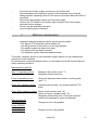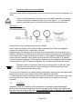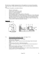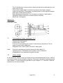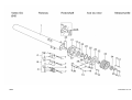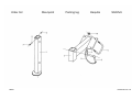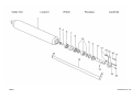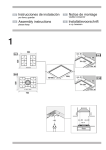
1
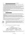
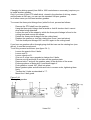
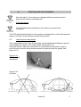
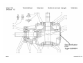
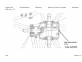
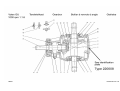
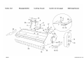
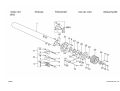
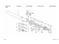
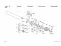
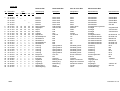
GU
Shredder
EC Declaration of conformity for machines
Manufacturer:
HMF KG d. Richard Frei& Co.
Adresse :
Handwerkerstraße Nr. 23
Code postal +town: I-39057 Eppan (BZ) Italy
declare that the following machines
HMF GU types : 200 225 250 75 and 300 nr…………………….
-
meets the requirements of the directive
Directive 98-37-EC
and the national legislation concerning the execution of this directive
-
meets the requirements of further EEC directives (only fill in if applicable)
and further declare that ;
the following (parts of ) harmonised norms have been applied
-
EN 292-1 1994 / EN 292-2 1996
EN 745 1999
Made in Eppan on : ……………………
……………………………
(signature)
Richard Frei
General Manager.
USER'S MANUAL AND PARTS LIST
VOTEX GU SHREDDER
Applicable to the following types:
GU 200
GU 225
GU 250
GU 275
GU 300
delivered after 01 December 2001
VOTEX B.V.
P.O. Box 30
6666 ZG HETEREN
The Netherlands
tel +31(0)26-4790600
fax +31(0)26-4790599
HK001
Internet : www.votex.nl
E-mail : [email protected]
Votex GU
Index
Page
1.
Introduction
5
2.
Safety
1.
Safety instructions
2.
Pictograms
3.
Type plate
6
6
11
13
3.
Technical specifications
14
4.
Transport and storage of the shredder
14
5.
Putting the shredder into operation
1.
Coupling the shredder to the tractor
2.
Connecting to tractor hydraulic system
3.
Mounting the PTO shaft
4.
Conversion of the shredder (from front to 'pulled')
15
15
16
16
16
6.
Working with the shredder
1.
PTO shaft speed
2.
Adjusting the cutting height
3.
Adjusting the rake teeth
4.
Vibrations in the shredder
5.
Uncoupling the shredder
18
18
18
19
19
19
7.
Maintenance
1.
Hammers, bolts and hammer mountings
2.
Protection
3.
Greasing points
4.
Hydraulic system
5.
Gearbox
6.
V-belt transmission. Removing and mounting the
V-belt guard and V-belts
7.
V-belt tensioning
8.
Winter storage
20
21
21
22
23
23
Votex GU
24
24
25
2
8.
Scrapping the shredder
25
9.
Appendix
A. Ordering parts
B. Liability and warranty
C. Notes
D. Conversion table
E. Tightening moments
25
25
26
26
27
27
Votex GU
3
1.
Introduction
Your have acquired a Votex GU shredder. We wish you much success with this
machine and thank you for your confidence in our organization. This manual is
intended for end users and service engineers. Work that may only be done by
service engineers is indicated as such in this book.
This manual contains complete information about safety, operation and maintenance
of the Votex GU shredders. We urge you to study this manual carefully, and then
keep it in a safe place for future reference.
Following the rules and recommendations herein described will ensure a properly
operating machine and reduce the risk of accidents!
The Votex GU shredder is a machine with which plant growth is struck off by heavy
hammers fixed to a fast-rotating shaft, then reduced and thrown back to the ground
through a hood.
The machine is intended to be used with tractors with a minimum wheel track of 1.50
m. It enables you to mow and shred grass, weeds and wood wildshoots having a
maximum diameter of 8 cm.
The machines have been designed for mowing:
- grass, and shredding wood wildshoots
- fallow grounds
- landscape maintenance
Important!
Any other use is not in accordance with the intended purpose!
The tractor operator must be appropriately qualified and have experience in driving
tractors.
The Votex GU shredder must not be used for mowing operations in the vicinity of
areas presenting fire and/or explosion hazards.
The shredder may be used only when the ground roller rests on the ground with its
full width.
Votex B.V. is constantly working on improving its products. It therefore reserves the
right to make any such changes, modifications and/or improvements as it deems
necessary. However, this does not imply any obligation on its part to make such
changes, modifications and/or improvements to machines previously supplied.
Votex GU
4
2.
2.1.
Safety.
Safety instructions.
This symbol points to acute danger to the life and/or health of human
beings and animals!
This symbol is a warning of possible damage to the mower if the user
does not follow the instructions.
This gives the user suggestions/recommendations for performing
certain tasks safer and easier.
-
-
-
-
-
Study the user's manual thoroughly so that you will be aware of situations
that may cause danger. Make sure you are familiar with the operation of the
tractor, and, in particular, how to stop it in an emergency. Pass all safety
instructions on to other users!
Never let the rotor shaft run when the ground roller is not resting on the
ground with its full length!
The exhaust gases of combustion engines contain carbon monoxide, an
odourless and lethal poison. So, never let the tractor engine run in a
confined space.
In addition to the specific directions contained in this user's manual, also
observe the general regulations in force with regard to safety and the
prevention of accidents!
The pictograms on the machine provide important directions for safe use.
Following these directions will serve your own safety. Replace any
damaged pictograms!
Wear ear protectors at noise levels exceeding 85 dB(A)! Never when using
public roads, however!
When using the machine, wear as much as possible close-fitting clothes!
When using public roads, always observe the road traffic regulations in
force!
Tractors with machines attached to them may be driven only by
appropriately qualified persons with sufficient experience!
Observe the maximum admissible transport dimensions!
If necessary, fit a lighting beam and/or warning signs!
For road transport, put the machine into the appropriate position and lock it
in accordance with directions (see chapter 4)!
When driving on the road with the machine raised, make sure the operating
lever of the lifting device has been secured against unintentional lowering!
Votex GU
5
-
If necessary, fit front weights. Always do so in accordance with the
instructions of the tractor manufacturer. Observe the requirements for the
maximum admissible axle load/total weight and the minimum front axle load
required (road traffic regulations)!
Do not take any passengers to ride along with you on any part, irrespective
of their age!
Hoses and cables for cylinders and lighting are to be disposed in such a
way that they cannot be damaged under any transport and operating
conditions. Be especially mindful of the fact that wrongly placed hoses may
activate unintended movements or impede necessary functions!
When taking bends, always bear in mind the greater width and length of
your tractor and the greater mass (inertia) of the tractor and mower!
Before driving off and putting the shredder into operation, look around the
machine and the tractor, making sure there are no persons within the
working range. Make sure you have an unobstructed view!
It is prohibited to come within the shredder's working and danger range.
-
-
-
Keep your distance! Objects (stones and the like) may be hurled
away.
-
Operate the shredder only when it is complete and all safeguards are intact.
The speed must be adapted to the terrain and working conditions!
It is dangerous to work with the tractor on slopes!
Do not mow with the machine on slopes having a gradient of more than 5%!
Mow only in daylight or good artificial light!
-
1.
2.
3.
-
RESIDUAL RISK! The safety guards on the Votex shredders meet the
relevant requirements as set by the European Commission!
Nonetheless, there will be some residual risk to be taken into account.
Objects in the terrain may be picked up and hurled away by the
hammers! This may cause serious injury or damage up to a distance of
about 50 metres!
In order to minimize this risk, act in accordance with the following safety
recommendations:
Always proceed in accordance with the requirements of the road maintenance
authority and observe the local ordinances and regulations.
If possible, close off roads, cycle paths, footpaths or bridle paths. If this is not
feasible, use a mobile road barrier so that road users will stay at a safe
distance from the machine.
Close off navigable waterways when you have to mow along them. If this is
not feasible, put up warning signs!
After bumping into an obstacle, check the shredder for any damage.
Immediately repair any damage before resuming working with the machine!
Votex GU
6
Stay outside the link-motion range of moving parts!
-
Make sure to avoid toppling over! Work only on sufficiently solid ground!
The following measures must be taken when leaving the tractor and/or
when work is to be done on the machine or PTO shaft:
- Switch off the PTO shaft.
- Put the gear lever of the tractor into neutral.
- Pull the parking brake of the tractor.
- Set the machine entirely down.
- Stop the tractor motor and remove the key from the ignition lock.
- Always wait for the rotor shaft to stop completely before approaching the
machine!
Machine is still coming to a standstill! Stay away from rotating parts until
they have stopped completely!
-
Make sure the supporting leg is in the lower locked position when coupling
or uncoupling the shredder!
Proceed very carefully when coupling and uncoupling the shredder. Be
particularly alert to the danger of getting trapped due to accidental operation
of the lifting device. Secure the machine laterally by sufficiently tightening
the stabilizers.
PTO shaft:
-
-
-
Only use the PTO shaft with freewheel specified by the manufacturer.
Protecting tubes and guards at the PTO shaft and the guards on tractor and
machine must be properly fixed and in good condition!
Ensure the specified overlapping of PTO shaft halves and protecting tubes,
both in the transport and operating position (see user's manual of PTO
shaft manufacturer).
The PTO shaft may be coupled and uncoupled only when the tractor engine
has stopped, the ignition key has been removed, and the machine rests on
the ground.
Always ensure that the PTO shaft is properly mounted and blocked!
Secure the guard of the PTO shaft against turning with the shaft by
fastening both chains to a fixed point on the tractor and machine sides!
Votex GU
7
-
-
Before switching on the PTO shaft, make sure that the speed and direction
of rotation of the PTO shaft correspond to the machine to be driven! The
speed and direction of rotation are indicated on the shredder by a
pictogram!
The rpm indicated must never be exceeded!
Never switch the PTO shaft on when the engine is not running!
Stay away from a rotating PTO shaft!
Always switch the PTO shaft off when the angles of the PTOs threaten to
become too great!
Hang an uncoupled PTO shaft into the bracket provided for this purpose on
the three-point linkage!
Fix the protective bush onto the PTO shaft of the tractor as soon as the
PTO shaft has been uncoupled!
Hydraulic system (if provided)
-
A hydraulic system operates under high pressure!
If a leak occurs in it, depressurize the system immediately, collect oil
leaking away, and replace defective parts!
Never put your finger to a hydraulic leak!
Liquid under high pressure easily penetrates skin and clothes, and
causes serious injury. If this should happen, consult a physician
immediately! Oil leaking away is quite harmful to the environment!
Take measures to prevent oil leakage!
-
-
-
Regularly check hydraulic hoses, lines and all connections. Replace them
when damaged or aged. New hoses must meet the technical requirements
of the manufacturer!
Shut down the tractor engine, remove the ignition key and depressurize the
hydraulic system before coupling or uncoupling the machine or before doing
any work on the hydraulic system.
Immediately fit the dust caps onto disconnected hydraulic hoses.
Lay hoses in such a way as to exclude any soiling and damage!
Votex GU
8
Maintenance and inspections:
Maintenance and inspections on the underside of the machine must
never be carried out when the machine is held only by the tractor
lifting device. Always take special precautions in order to prevent an
unexpected lowering of the machine. Use a tackle or horse whose
minimum carrying capacity exceeds or is equal to the mass of the
machine (See type plate).
Vibrations in the shredder are usually caused by the rotor shaft being
out of balance. These vibrations may cause serious damage to the
shredder. When during mowing operations there is a clearly
noticeable increase in vibrations or change in sound produced by the
shredder, stop operations immediately, locate the cause and eliminate
it before continuing the work!
-
-
Regularly check hammers, bolts and hammer mounting plates on the rotor
shaft for wear. For minimum dimensions required, see chapter 7.1!
Make sure the rotor shaft is provided with all hammers equally worn off!
Damaged or worn hammers and bolts must be replaced immediately!
Immediately replace rotor shafts that are out of balance or rotor shafts with
worn mounting plates!
Regularly check the metal protecting flaps on the front side of the cutting
head. Make sure the flaps can rotate freely at all times. Replace bent or
worn flaps immediately. It is prohibited by law to work with this machine
without protecting flaps/guards or if they are worn!!
Only such persons are allowed to work with and/or on the shredder as are
perfectly familiar with it and well aware of possible dangers!
Any and all work to be done on the shredder is allowed to be carried out
only with solid and proper tools.
Votex GU
9
2.2.
Pictograms (see figure 2.1.):
1.
Caution! Hydraulic system under high pressure. Do not attempt to seal a
leak by hand. Read the user's manual (Votex no.20.10.618)
2.
Direction of rotation and maximum PTO shaft speed 540 rpm (Votex no.
20.10.600)
3.
Direction of rotation and maximum PTO shaft speed 1000 rpm (Votex no.
20.10.602)
4.
Caution! Danger of getting trapped by V-belt transmission (Votex no.
20.10.621)
5.
Before putting the machine into service, read the user's manual and safety
instructions and observe them. (Votex no. 20.10.604)
6.
Before carrying out any maintenance and repairs, shut down the engine
and remove ignition key. (Votex no. 20.10.609)
7.
Do not touch any rotating parts before the machine has come to a standstill.
(Votex no. 20.10.605)
8.
Greasing point
9.
Never come within the link-motion range of moving parts.
(Votex no. 20.10.608)
10.
Lift the machine only at the lifting lug. (Votex no. 20.10.610)
11.
Caution! Rotating shaft! (Votex no. 20.10.620)
12.
When operating the lifting device, stay outside the lifting range of the threepoint linkage. (Votex no. 20.10.611)
13.
Keep your distance! Never put your feet under the cutting cap!
(Votex no. 20.10.612)
14.
Keep your distance when the rotor shaft is rotating. (Votex no. 20.10.606)
Votex GU
10
Figure 2.1 : Pictograms and type plate on the machine
Votex GU
11
2.3.
Type plate.
The type plate is provided on the gearbox support.
The plate contains the following data:
-
Brand name
: VOTEX
Name and address of manufacturer :
-
CE marking
Model
Type
Serial number
Year of construction
Mass
Nominal output
Max. hydraulic operating pressure
Maximum R.P.M. of cutting rotor
: CE
: GU
:
:
:
:
:
: 180 bars
: 2100 rpm
Votex GU
12
3.
Technical specifications
Votex GU
type
200
225
Cutting width in cm
200
225
Cutting height in cm 3-9
3-9
Mass in kg
695
745
Max. side shift in rel. to 140
162
tractor centre in cm
Mounting category
I-II
II-III
Mounting
Rear
Rear
or front or front
PTO shaft rpm
540/100 540/1000
250
250
3-9
795
175
275
275
3-9
840
187
300
300
3-9
885
199
II-III
Rear
or front
540/1000
II-III
Rear
or front
540/1000
II-III
Rear
or front
1000
For all types, the sound pressure produced at normal operating speed amounts to 94
dB(A), measured at a height of 1.60 m and at a distance of 1 m from the shredder.
4.
Transport and storage of the shredder.
Transport of the shredder is to take place with the rotor shaft standing still and the
lateral-movement cylinder (if provided) in the shortest position (shredder as narrow
as possible).
The shredder (when not coupled to a tractor) may be moved only when the following
conditions have been met:
supporting leg in lower position and locked,
cylinder for sideshift in the shortest position (shredder as narrow as
possible),
PTO shaft, if mounted, in the bracket provided for this purpose on the threepoint linkage.
When not coupled to a tractor, the shredder can only be moved by lifting it at a lifting
lug (see pictogram on cutting head). To this end, use a lifting gear having a lifting
capacity exceeding or equal to the mass of the shredder. For this, see the type plate
on the machine.
Place the shredder on horizontal solid ground with a minimum
strength of 400 kPa (approx. 4 kg/cm²).
When the shredder is to be stored, the cylinder must be in its fully slid-in position in
view of the risk of damage or corrosion to the chromium-plated piston rod.
For winter storage, we refer to chapter 7.8.
Votex GU
13
5.
Putting the shredder into operation.
Prior to coupling the shredder, check whether the data (see figure 5.1.) on direction
and speed of rotation as stated on the machine correspond to the direction and
speed of rotation of the tractor PTO shaft.
Figure 5.1
Speed and direction
of rotation of PTO
shaft
5.1.
Coupling the shredder to the tractor.
The Votex GU 200 shredder can be mounted to tractors using a cat. I or II linkage
mechanism. All other models are equipped with a cat. II-III linkage.
To couple the shredder to the tractor, proceed as follows:
-
place the tractor in front of the shredder so that the drawbars can be
coupled to the machine,
pull the parking brake of the tractor and put the gear lever(s) into neutral.
When operating the linkage mechanism, stay outside the lifting range
of the three-point linkage.
-
fix both drawbars to the shredder using the lifting-arm pins and fit the spring
clips,
turn off the tractor engine and remove the ignition key,
mount the PTO shaft and both chains of the guard,
mount the top bar, top-bar pin(s) and secure them,
adjust the machine horizontally by turning the top bar,
reduce the lateral play of the shredder in the three-point linkage to a
minimum.
Votex GU
14
5.2.
Connecting the tractor hydraulic system. (if provided)
Before connecting the hydraulic hoses, turn off the tractor engine, remove ignition
key, and depressurize the tractor hydraulic system!
The hydraulic hoses of the Votex GU are provided with 1/2" BSP (male) connectors.
The female connectors should be on the tractor. A double-acting control valve is
required for the lateral movement of the cutting headhead. Any costs to be incurred
for adapting the tractor hydraulic system will be for account of the user.
After disconnecting the hydraulic hoses, the dust caps included in the delivery must
be pushed on the quick connectors so as to prevent sand and dirt from getting into
the tractor hydraulic system.
Damage to the tractor hydraulic system cannot be charged to the manufacturer.
Normal use of the Votex GU shredder will not lead to the tractor hydraulic system
being loaded heavily.
5.3.
Mounting the PTO shaft.
Before mounting the PTO shaft, turn off tractor engine and remove ignition key!
Use the PTO shaft of the Votex GU shredder in accordance with the manufacturer's
instructions.
The PTO shaft is to be mounted to the side of the machine with the ratched
freewheel. Make sure that PTO shaft connections are well secured to tractor and
shredder. Only use a complete PTO shaft guard provided with securing chains which
must be firmly fastened to the tractor and shredder so that it cannot turn with the
shaft.
Take into account all angles that the PTO shaft can conceivably form.
In addition, both the tractor and the machine must be provided at the shaft ends with
solid guards overlapping the PTO shaft guard by at least 50 mm.
The PTO shaft must not be too long. To determine the proper shaft length,
the upward movements and swinging of the machine and the turning
inwards and outwards of the top bar must be taken into account. For
mounting, shortening and maintenance, see the user's manual of the PTO
shaft!
5.4
'Pulled' to front conversion of the shredder or vice versa.
When converting from 'pulled' to front, the direction and speed of rotation of the PTO
shaft of the tractor are to be taken into account.
Votex GU
15
Changing the driving speed (from 540 to 1000 revolutions or conversely) requires you
to install another gearbox.
Only if you have a front PTO shaft which, viewed in the direction of driving, rotates
anticlockwise at 540 rpm, you can use the standard 540-rpm gearbox.
In all other cases you will need another gearbox.
To convert the three-point linkage from 'pulled' to front, proceed as follows:
-
Remove the PTO shaft from the gearbox.
Hang the three-point linkage from a tackle or fork-lift truck so that it cannot
drop when being detached.
Loosen the nuts of the straps by which the three-point linkage is fixed to the
cutting head and remove the straps.
Detach the three-point linkage from the cutting head.
Replace the gearbox or turn the existing box round. (see text below)
Turn the three-point linkage 180° and fix it again to the cutting head
If you have no gearbox with a through-going shaft but can use the existing box (see
above), it must be turned round.
To do this, proceed as follows: (see figure 5.4.1)
-
Loosen the guard of the V-belts.
Loosen nuts C.
Loosen check nut D.
Give nut G a few turns upwards to slacken the V-belts.
Remove nuts M and bolts R and take off the gearbox plate.
Remove bolts T and pull the gearbox away in the direction of the arrow.
Exchange places of drain plug U and bleed nipple V.
Push gearbox, turned 180°, back into place.
Mount gearbox plate and all bolts and nuts in reverse order, tightening them
firmly.
Tension the V-belts as described in 7.7.
Mount the V-belt guard.
Figure 5.4.1
Turning the gearbox
Votex GU
16
6.
Working with the shredder.
After the initial 1-2 running hours, retighten all bolt connections and in
particular all hammer mounting bolts.
6.1.
PTO shaft speed.
The PTO shaft speed indicated on the machine must never be
exceeded!
The PTO shaft speed indicated on the machine corresponds to a rotor shaft speed of
approx. 2100 rpm, which ensures the best cutting action.
6.2.
Adjusting the cutting height.
The cutting height of the Votex GU shredder can be adjusted by shifting the groundroller supports in relation to the cutting head. (See figure 6.2.1)
Using the top bar, adjust the machine so as to be perfectly horizontal in order to
prevent wood or stones being hurled around from getting under the guard! (See
figure 6.2.2)
Figure 6.2.1
Cutting-height
adjustment
Figure 6.2.2
Levelling
Votex GU
17
WRONG
6.3
RIGHT
Adjusting the rake teeth.
The Votex GU is supplied with the adjustable rake teeth as a standard feature. These
teeth ensure a better pickup of prunings, trimmings and wood wildshoots. Since the
teeth are inclined forwardly, they bring plant growth up which is then hit by the
hammers. (see figure 6.3.1) As a result, the hammers need not be adjusted very low
above the ground, thus extending the life of the hammers. In addition, the rake teeth
prevent prunings that are too big from being hurled out of the shredder.
Adjust the rake teeth so that they almost touch the ground.
When mowing grass with the machine, you must put the teeth upwards or remove
them entirely. You can adjust the height of the rake teeth by placing the split pin into
another hole. (see figure 6.3.1.2)
Figure 6.3.1
Rake-teeth adjustment
6.4.
Figure 6.3.1.2
Vibrations in the machine.
When during operations there is a clearly noticeable increase in vibrations in the
shredder or change in sound produced by the shredder, then stop operations
immediately, locate the cause and eliminate it (see 7.1.) before continuing the work!
6.5
Uncoupling the shredder.
Place the shredder on horizontal solid ground with a minimum
strength of 400 kPa (approx. 4 kg/cm²)
Be alert to residual pressure when uncoupling hydraulic hoses!
-
pull the parking brake of the tractor and put the gear lever(s) into neutral,
place the supporting leg into the lower position and lock it,
lower the machine to the ground,
Votex GU
18
-
-
shut down the tractor engine and remove the ignition key,
then depressurize the hydraulic system of the machine by moving the
sliding-cylinder operating levers on the tractor a few times back and forth (if
provided),
disconnect the hydraulic hoses and fit the dust caps,
remove the PTO shaft on the tractor side and place it into the bracket
provided for this purpose,
remove top-bar and lifting-arm pins,
remove lighting plug if mounted.
7.
Machine maintenance.
Inspection and maintenance may be carried out only when:
- The tractor PTO shaft has been switched off
- The lifting device of the tractor is in its lower position
- The tractor engine has been shut down
- The ignition key has been removed
- The hydraulic system has been depressurized
The safety, reliability and life of your shredder largely depend on the maintenance
carried out on the machine.
By following the recommendations below, you are assured of a well functioning and
safely operating machine.
Maintenance schedule
After 1-2 operating hours:
Retension the V-belts (see 7.7)
Retighten all bolts and nuts
Every 4 operating hours:
Check the hammers and hammer mounting bolts
(see 7.1)
Every 8-10 operating hours:
Lubricate ground roller, any wheels and the PTO
shaft.
Every 30-40 operating hours: Check V-belt tension (see 7.6)
Check oil level in gearbox (see 7.5)
Retighten all bolts and nuts. Check the hydraulic
hoses and couplings for wear and damage.
After the first 50
operating hours:
Change the oil in the gearbox
Every 500-800
operating hours
or once a year:
Change the oil in the gearbox
Votex GU
19
7.1
Hammers, bolts and mounting plates.
Hammers, bolts and mounting plates on the rotor shaft must be checked regularly for
wear.
Never work with hammers, bolts and mounting plates that do not meet the
minimum-dimension requirements! For this, see figure 7.1.1. Immediately
replace any parts that do not meet the minimum dimensions required!
See figure 7.1.1
Minimum dimensions
of hammer mountings
Hammer mounting nut tightening moment: 125Nm
Worn hammers result in poor cutting quality that looks bad. When this happens,
replace all hammers and, if necessary, all bolts.
Replacing only the hammers that are most worn would render the rotor shaft out of
balance, resulting in vibrations which may cause serious damage to your shredder in
a very short time. Vibrations may point to one or more (heavily) damaged hammers
and/or hammer brackets. Also, objects wound around the rotor shaft (e.g. barbed
wire) may cause vibrations. In the event of vibrations and/or changes in the shredder
sound, switch off the PTO shaft immediately, then locate and eliminate the cause!
Excessive wear of hammers, bolts and mounting plates on the rotor shaft
may be caused by too low a rotor shaft speed and/or frequent contact
of the hammers with soil or water.
If one or more hammers have been (heavily) damaged, replace them with specimens
that are worn to the same degree as the other hammers mounted.
If, after taking the above measures, there are still vibrations in the machine, this may
point to a bent rotor shaft. Contact your dealer. Never try to repair a rotor shaft
yourself!
7.2.
Protection.
Regularly check the condition of the protection. Immediately replace damaged,
bent or worn metal protecting flaps on the front side of the cutting head. Make sure
the flaps can turn freely at all times. It is prohibited by law to operate this machine
without protecting flaps/guards or if they are worn!!
Votex GU
20
7.3.
Greasing points.
The following greasing points are to be lubricated with a multipurpose lithium grease.
Greasing points:
A
Rotor shaft bearings (2 nipples)
Every 2 days. Each time not more than 2-3 shots per bearing
with the grease gun since they are closed bearings.
B
Ball bearings of ground roller (2 nipples)
Every day, generously introduce grease until it comes out at the groundroller shaft
The PTO shaft must be lubricated according to the lubrication schedule of the
manufacturer.
7.4.
Hydraulic system. (if provided)
The hydraulic oil in hoses and cylinder is replaced automatically when replacing the
hydraulic oil of the tractor. It is therefore important to follow the pertinent instructions
of the tractor manufacturer.
7.5.
Gearbox.
The oil content required for the gearbox is 2.5 l of Gear Oil SAE 90 API GL4. The oil
in the gearbox is to be changed for the first time after 50 running hours, and
subsequently once in a season. In addition, it is necessary to check the gearbox
regularly for any leakages.
Changing the oil: (see figure 7.5.1)
Votex GU
21
The best way to handle changing the oil in the gearbox is to remove the gearbox.
This may seem a rather laborious method, but it is by far the easiest and quickest
way.
To remove the gearbox, proceed as follows:
-
Remove V-belt guard
Loosen nuts C and check nut D
Give nut G a few turns upwards
Remove nuts M and bolts T
Pull the gearbox away in the direction of the arrow
Remove bleed nipple V and drain plug U and let the oil run into a drain pan.
Place the drain plug back, remove level plug X and fill the gearbox with the
specified amount of oil. Then place bleed nipple V and level plug X back.
Mount the gearbox and all bolts and nuts in reverse order of removal, and
make sure the V-belts are tensioned correctly.
Figure 7.5.1
Changing gearbox oil
7.6
Removing and mounting the V-belts. (see figure 7.6.1)
-
Loosen the fixing bolt of the V-belt guard,
Remove the V-belt guard,
Slightly loosen 2 bolts C by which the drive housing is fixed to the side
plate,
Loosen lock nut D of the V-belt tensioning bolt,
Loosen V-belt tensioning nut G to the extent that you can remove the Vbelts,
Remove the old belts and fit the new belts around the pulleys,
Turn nut G to tension the V-belts,
Pull (for instance using a spring balance) at a belt midway between the two
pulleys with a force F of 5 daN (5.1 kg).
-
Votex GU
22
-
The V-belt tension is correct when in doing so the belt is pulled away by not
more than 5-6 mm.
Check with straight edge K whether the pulleys are properly aligned,
Adjust the alignment, if necessary, by placing one or more rings N between
base plate O and gearbox plate P,
After adjusting the alignment, it is necessary to recheck V-belt tension,
Retighten all bolts and nuts in reverse order of removal,
Mount the V-belt guard.
Figure 7.6.1
Mounting and
removing V-belts
7.7
Tensioning the V-belts. (see figure 7.6.1)
-
Remove the V-belt guard,
Loosen nuts C and D,
Turn nut G until reaching the correct V-belt tension (see above). Do not
forget to check pulley alignment,
Retighten nuts C and D, and mount the V-belt guard.
Note:
First-time retensioning must be carried out after about 1-2
operating hours. The tension and condition of the V-belts are
subsequently to be checked at regular intervals.
7.8.
Winter storage.
In the event the machine is put out of service for an extended period of time, it will be
necessary to carry out an extensive cleaning. Thereupon, lubricate all greasing points
(see chapter 7.3.) and change the gearbox oil (see chapter 7.5.). After this, have the
machine run for a few minutes.
Votex GU
23
8.
Scrapping the machine.
When the machine is to be scrapped, you must take the following measures:
place a drain pan under the gearbox and drain the oil,
remove all hydraulic components and collect the oil,
slide the cylinder a few times in and out, and collect the residual oil,
remove grease from:
bearing housings including bearings,
ground-roller bearings
Remove all rubber and synthetic parts and dispose of them in accordance with the
regulations in force. Dispose of the grease and oil in accordance with the regulations
in force. Dispose of the remaining parts as scrap iron.
Appendix.
A.
B.
C.
D.
E.
Ordering parts.
Liability and warranty.
Notes.
Conversion table.
Tightening moments.
Votex GU
24
A.
Ordering parts.
Your order for parts should contain the following details (see type plate):
Model
Type
Serial number
Part number, part name and quantity
For any part whose number cannot be determined with certainty, you may send the
original in order to avoid delivery of a wrong part. The parts of the figures in this
manual may show differences with the original because due to design adaptations or
improvements a particular part may have been changed prior to the release of a new
edition of this book. It is therefore advisable not to rely only on the illustrations. Use
original Votex parts only so that you will be assured of excellent quality and a good
fit.
B.
Liability and warranty.
Votex B.V. guarantees the proper operation of your machine for a period of 12
months after delivery, provided the instructions contained in this manual are followed
as described.
The machine shall be used only by persons who have thoroughly studied
this manual beforehand, and are well aware of the dangers that may result
from not properly following pertinent instructions. This also applies to the
persons responsible for adjusting and servicing the machine.
The machine shall be used only for the specified purposes.
Always duly observe the safety instructions.
Replacement parts will be compensated within the period of
guarantee only if they have been ordered from Votex b.v.
Use only original Votex parts/components and the specified lubricants.
Always duly observe the local safety regulations as in force with regard to
the prevention of accidents, transport safety and traffic regulations.
Important!
This manual applies to the original Votex technical design and
construction of your machine. Votex B.V. can therefore not be held
responsible and disclaims any liability for any damage resulting from
any technical alteration or change independently made to the machine
and from the use of any parts other than those from Votex. This
provision also applies to the use of any other lubricants, improper or
insufficient maintenance and any repairs carried out improperly,
without prior consultation with Votex B.V.
Please note that:
In case this manual is not correctly complied with, Votex B.V. cannot
be held liable for any warranty claims within the period of guarantee.
The terms of delivery and payment used by Votex B.V. are the terms
and conditions of the Metaalunie. These have been lodged with the
Registry of the Court of Rotterdam. They include the Algemene
Handelsvoorwaarden Landbouwwerktuigen en – uitrustingen (AHL)
Votex GU
25
-
C.
(general terms of business for agricultural machinery and equipment).
If the guarantee card and user declaration have not been correctly and
completely filled in and returned to Votex b.v. within 14 days after
delivery, warranty requests, if any, will not be considered.
Notes.
All rights reserved.
No part of this book may be reproduced and/or made public by means of reprint,
photocopy, microfilm or in any other form whatsoever, without the express prior
permission in writing from Votex B.V. This also applies to the accompanying
drawings and diagrams.
Votex B.V. reserves the right to adapt parts for improvement at any time, without
prior notice to the buyer.
Likewise, the contents of this manual may be changed accordingly without prior
notice. For information about adjustments, maintenance or repairs not covered by
this manual, we recommend that you contact the technical department of your
supplier.
Votex GU
26
D.
Conversion table.
Length
1 m = 100 cm = 1000 mm
Volume
1 m3 = 1000 dm3 = 1000 l
Force and weight
1 N = 0.102 kg (f) = 0.102 kp
Pressure and stress
1 bar = 0.987 atm = 100 kPa = 100 kN/m
Tightening moment
1 Nm = 0.102 kg (f) m
Power
1 kW = 1000 W = 1.36 pk = 1.36 cv =
1.34 hp
Number of revolutions
1 omw./min = 1 rpm = 1 U/min = 1 tr/mn = 1 min-1
Speed
1 km/h = 0.278 m/s
E.
Tightening moments.
All bolt connections must be tightened according to the table below, unless otherwise
stated in the manual or parts list.
Thread
M 8
M 10
M 12
M 14
M 16
M 18
M 20
Tightening moment
(Nm)
24
49
84
133
205
290
410
Votex GU
27
Votex GU
Votex GU
200
no.
onderdeel
nummer
aantal
1-19
1
2
3
4
5
6
7
8
9
10
11
12
13
14
15
16
17
18
19
73.31.522
73.31.477
73.31.480
73.31.483
73.31.486
10.02.092
10.04.209
10.04.215
73.31.495
11.02.008
11.02.016
11.05.016
12.11.008
12.01.008
12.01.016
73.31.507
73.31.510
20.01.029
73.31.516
73.31.519
HK001
1
1
1
3
3
1
2
2
6
1
4
12
1
1
4
2
1
3
3
1
Driepuntsframe
Kat 1-2
Omschrijving
Three points linkage
Cat 1-2
Discription
Attelage 3-points
Cat 1-2
Designation
Dreipunktaufhängung
Kat 1-2
Beschreibung
Driepuntsframe cpl.
Driepuntsframe
Framebuis
Steun
Steun
Zeskanttapbout
Zeskantbout
Zeskantbout
Strop
Zeskantmoer
Zeskantmoer
Borgmoer
Sluitring
Veerring
Veerring
Werktuigpen
Topstangpen
Borgveer dubbel
Ketting cpl.
Kruiskoppelingsas houder
Three points linkage cpl.
Three points linkage
Frame tube
Support
Support
Bolt
Bolt
Bolt
U bolt
Nut
Nut
Lock nut
Washer
Spring washer
Spring washer
Link pin
Top link pin
Gripclip double
Chain cpl.
Drive shaft support
Attelage trois points cpl.
Attelage trois points
Tube de Châssis
Support
Support
Vis
Vis
Vis
Etrier
Écrou
Écrou
Écrou autofreiné
Rondelle
Rondelle grower
Rondelle grower
Broche
Broche troisieme point
Goupille beta double
Chaîne cpl.
Support de cardan
Dreipunkt aufhängung kpl.
Dreipunkt Aufhängung
Ramen rohr
Stütze
Stütze
Sechskantschraube
Sechskantschraube
Sechskantschraube
Klemmbügel
Mutter
Mutter
Sicherungsmutter
Unterlegscheibe
Federring
Federring
Lenker bolzen
Bolzen
Federstecker doppelt
Kette kpl.
Gelenkwellehalter
technische info
GU kat.1-2
GU
GU
R
L
M8x30-8.8
M16x55-8.8
M16x90-8.8
M16-8.8
M8
M16
M16
M8
M8
M16
kat1-2 oud model
kat 1-2
4mm
2.2x290mm
onderdelen GU .xls
HK001
onderdelen GU .xls
Votex GU
225-250-275-300
no.
onderdeel
nummer
aantal
1-19
1
2
3
4
5
6
7
8
9
10
11
12
13
14
15
16
17
18
19
73.32.524
73.32.506
73.32.509
73.32.512
73.32.515
10.02.092
10.02.261
10.04.271
73.31.495
11.02.008
11.02.020
11.05.016
12.11.008
12.01.008
12.01.020
73.31.648
73.31.651
20.01.029
73.31.516
73.31.519
HK001
1
1
1
3
3
1
2
2
6
1
4
12
1
1
4
2
1
3
3
1
Driepuntsframe
Kat 2-3
Omschrijving
Three points linkage
Cat 2-3
Discription
Attelage 3-points
Cat 2-3
Designation
Dreipunktaufhängung
Kat 2-3
Beschreibung
Driepuntsframe
Driepuntsframe
Steun
Steun
Steun
Zeskanttapbout
Zeskanttapbout
Zeskantbout
Strop
Zeskantmoer
Zeskantmoer
Borgmoer
Sluitring
Veerring
Veerring
Werktuigpen
Topstangpen
Borgveer dubbel
Ketting cpl.
Kruiskoppelingsas houder
Three points linkage
Three points linkage
Support
Support
Support
Bolt
Bolt
Bolt
U bolt
Nut
Nut
Lock nut
Washer
Spring washer
Spring washer
Link pin
Top link pin
Gripclip double
Chain cpl.
Drive shaft support
Attelage trois points
Attelage trois points
Support
Support
Support
Vis
Vis
Vis
Etrier
Écrou
Écrou
Écrou autofreiné
Rondelle
Rondelle grower
Rondelle grower
Broche
Broche troisieme point
Goupille beta double
Chaîne cpl.
Support de cardan
Dreipunkt Aufhängung
Dreipunkt Aufhängung
Stütze
Stütze
Stütze
Sechskantschraube
Sechskantschraube
Sechskantschraube
Klemmbügel
Mutter
Mutter
Sicherungsmutter
Unterlegscheibe
Federring
Federring
Lenker bolzen
Bolzen
Federstecker doppelt
Kette kpl.
Gelenkwellehalter
technische info
GU Kat2-3
GU Kat2-3
GU Kat 2-3
R
L
M8x30-8.8
M20x60-8.8
M20x140-8.8
M16-8.8
M8
M20
M16
M8
M8
M20
Kat. 2-3
4mm
2.2x290mm
onderdelen GU .xls
HK001
onderdelen GU .xls
Votex GU
no. onderdeel
nummer
1
2
3
4
5
6
7
8
9
10
11
12
13
14
15
16
17
18
73.31.267
73.31.270
73.31.273
73.31.276
73.31.279
73.31.282
73.37.877
73.37.880
73.37.883
73.37.886
73.37.889
73.37.892
18.05.011
18.05.008
12.31.080
12.31.075
10.02.152
10.01.153
10.28.124
12.01.012
12.01.012
12.11.010
15.08.060
73.32.671
73.32.674
73.32.677
19.02.215
19.06.212
73.32.629
73.32.632
HK001
type
200 225 250 275 300
1
1
1
2
4
1
4
4
1
4
1
1
1
1
1
1
2
4
1
4
4
1
4
1
1
1
1
1
1
1
1
1
1
1
1
2
4
1
4
4
1
4
1
1
1
1
1
2
4
1
4
4
1
4
1
1
1
1
1
2
4
1
4
4
1
4
1
1
1
1
1
1
1
1
1
1
1
1
1
1
Aandrijving
Drive
Transmission
Antrieb
Omschrijving
Discription
Designation
Beschreibung
technische info
Lagerhuis
Lagerhuis
Lagerhuis
Lagerhuis
Lagerhuis
Lagerhuis
Aandrijfas
Aandrijfas
Aandrijfas
Aandrijfas
Aandrijfas
Aandrijfas
Kogellager
Kogellager
Zekeringsring
Zekeringsring
Zeskanttapbout
Zeskanttapbout
Cilinderkopschroef
Veerring
Veerring
Sluitring
Inlegspie
Afstandsbus
V-snaarschijf
V-snaarschijf
V-snaar
V-snaar
Conische klembus
Borgplaat
Bearing house
Bearing house
Bearing house
Bearing house
Bearing house
Bearing house
Drive shaft
Drive shaft
Drive shaft
Drive shaft
Drive shaft
Drive shaft
Ball bearing
Ball bearing
Circlip
Circlip
Bolt
Bolt
Cilinderheadscrew
Spring washer
Spring washer
Washer
Sunk key
Distance bush
V-belt pulley
V-belt pulley
V-belt
V-belt
Conical Bush
Lock plate
Cage de roulements
Cage de roulements
Cage de roulements
Cage de roulements
Cage de roulements
Cage de roulements
Arbre d'entraînement
Arbre d'entraînement
Arbre d'entraînement
Arbre d'entraînement
Arbre d'entraînement
Arbre d'entraînement
Roulement à billes
Roulement à billes
Circlip
Circlip
Vis
Vis
Vis à tête cilindrique
Rondelle grower
Rondelle grower
Rondelle
Clavette
Bague d'entretoise
Poulie à gorges
Poulie à gorges
Courroie
Courroie
Moyeu conique
Plaque de blocage
Lagergehause
Lagergehause
Lagergehause
Lagergehause
Lagergehause
Lagergehause
Antriebachse
Antriebachse
Antriebachse
Antriebachse
Antriebachse
Antriebachse
Kugellager
Kugellager
Sicherungsringe
Sicherungsringe
Sechskantschraube
Sechskantschraube
Zylinderkopfschraube
Federring
Federring
Unterlegscheibe
Paßfeder
Distanzbüchse
Keilriemenscheibe
Keilriemenscheibe
Keilrieme
Keilrieme
Spannbüchse
Sicherungsplatte
L=580mm
L=705mm
L=830mm
L=955mm
L=1045mm
L=1170mm
L=645mm
L=770mm
L=895mm
L=1020mm
L=1110mm
L=1235mm
6208-2RS1
6009-2RS1
80x2.5
75x2.5
M12x30-8.8
M12x35-8.8
M10x45
M12
M12
M10
12x8x60250SPB4
250SPB5
SPB-1500
XPB-1500
onderdelen GU .xls
HK001
onderdelen GU .xls
no.
1-22
1
2
3
4
5
6
7
8
9
10
11
12
13
14
15
16
17
18
19
20
21
22
Votex GU
540 rpm 1:3
type 220001
onderdeel aantal
nummer
73.92.201
73.33.629
73.31.957
73.31.960
73.31.765
13.03.033
12.35.080
73.31.894
18.01.014
73.31.789
18.11.013
11.11.338
18.11.010
73.31.966
17.01.028
73.31.969
12.33.040
10.28.061
73.31.693
26.10.536
73.33.635
17.01.014
10.02.120
HK001
1
1
1
1
2
2
1
1
3
1
2
2
1
1
1
1
4
2
1
1
1
8
Tandwielkast
Gearbox
Boitier à renvoie d'angle
Getriebe
Omschrijving
Discription
Designation
Beschreibung
technische info
Tandwielkast
Tandwielkasthuis
Kegelwiel
Aandrijfas
Typeplaatje
Shim
Zekeringsring
Kap
Kogellager
Shim
Kegellager
Kraagplug
Kegellager
Tandwielkastdeksel
Keerring
Pignonas
Zekeringsring
Cilinderkopschroef
Stop
Ontluchtingsnippel m.klep
Tandwielkastdeksel
Keerring
Zeskanttapbout
Gearbox plate
Gearbox case
Crownwheel
Drive shaft
Name plate
Shim
Circlip
Cap
Ball bearing
Shim
Tapered rolling bearing
Plug
Tapered rolling bearing
Gearbox cover
Seal ring
Pignon shaft
Circlip
Cilinderheadscrew
Plug
Air release nipple w.valve
Gearbox cover
Seal ring
Bolt
Boitier à renvoie d'angle
Boitier
Pignon
Arbre d'entraînement
Plaqque signalétique
Rondelle de réglage
Circlip
Couvercle
Roulement à billes
Rondelle de réglage
Roulement à rouleau conique
Bouchon filetée
Roulement à rouleau conique
Couvercle
Joint d'étanchéité
Axe de pignon
Circlip
Vis à tête cilindrique
Bouchon
Reniflard d'air avec valve
Couvercle
Joint d'étanchéité
Vis
Getriebe
Getriebegehäuse
Kegelzahnrad
Antriebachse
Typenschild
Paßscheibe
Sicherungsringe
Kappe
Kugellager
Paßscheibe
Kegellager
Verschlüßschraube
Kegellager
Getriebedeckel
Simmerring
Ritzel mit welle
Sicherungsringe
Zylinderkopfschraube
Stopfen
Entlüfter m.klappe
Getriebedeckel
Simmerring
Sechskantschraube
540 rpm 1:3
twk 220001
twk 220001
70x80x0.5
JS 80x4
6307
30308-J2
R3/8"
30208-J2
35x56x8
220001/220105/220108
40x2.5
M6x16
3/8"
R3/8
40x80x10
M10x25-8.8
onderdelen GU .xls
HK001
onderdelen GU .xls
no.
1-22
1
2
3
4
5
6
7
8
9
10
11
12
13
14
15
16
17
18
19
20
21
22
Votex GU
540 rpm 1:3
Tandwielkast
type 220005
onderdeel aantal Omschrijving
nummer
73.92.205
73.33.629
73.31.957
73.31.984
73.31.765
13.03.033
12.35.080
17.01.059
18.01.014
73.31.789
18.11.013
11.11.338
18.11.010
73.31.966
17.01.028
73.31.969
12.33.040
10.28.061
73.31.693
26.10.536
73.33.635
17.01.014
10.02.120
HK001
1
1
1
1
2
2
1
1
3
1
2
2
1
1
1
1
4
2
1
1
1
8
Tandwielkast
Tandwielkasthuis
Kegelwiel
Aandrijfas
Typeplaatje
Shim
Zekeringsring
Keerring
Kogellager
Shim
Kegellager
Kraagplug
Kegellager
Tandwielkastdeksel
Keerring
Pignonas
Zekeringsring
Cilinderkopschroef
Stop
Ontluchtingsnippel m.klep
Tandwielkastdeksel
Keerring
Zeskanttapbout
Gearbox
Boitier à renvoie d'angle
Getriebe
Discription
Designation
Beschreibung
technische info
Gearbox plate
Gearbox case
Crownwheel
Drive shaft
Name plate
Shim
Circlip
Seal ring
Ball bearing
Shim
Tapered rolling bearing
Plug
Tapered rolling bearing
Gearbox cover
Seal ring
Pignon shaft
Circlip
Cilinderheadscrew
Plug
Air release nipple w.valve
Gearbox cover
Seal ring
Bolt
Boitier à renvoie d'angle
Boitier
Pignon
Arbre d'entraînement
Plaqque signalétique
Rondelle de réglage
Circlip
Joint d'étanchéité
Roulement à billes
Rondelle de réglage
Roulement à rouleau conique
Bouchon filetée
Roulement à rouleau conique
Couvercle
Joint d'étanchéité
Axe de pignon
Circlip
Vis à tête cilindrique
Bouchon
Reniflard d'air avec valve
Couvercle
Joint d'étanchéité
Vis
Getriebe
Getriebegehäuse
Kegelzahnrad
Antriebachse
Typenschild
Paßscheibe
Sicherungsringe
Simmerring
Kugellager
Paßscheibe
Kegellager
Verschlüßschraube
Kegellager
Getriebedeckel
Simmerring
Ritzel mit welle
Sicherungsringe
Zylinderkopfschraube
Stopfen
Entlüfter m.klappe
Getriebedeckel
Simmerring
Sechskantschraube
540 1:3 DGA
twk 220001
twk 220001
twk 220005
70x80x0.5
JS 80x4
35x80x10 BA
6307
30308-J2
R3/8"
30208-J2
35x56x8
220001/220105/220108
40x2.5
M6x16
3/8"
R3/8
40x80x10
M10x25-8.8
onderdelen GU .xls
HK001
onderdelen GU .xls
no.
1-24
1
2
3
4
5
6
7
8
9
10
11
12
13
14
15
16
17
18
19
20
21
22
23
24
Votex GU
1000 rpm 1:1.6
type 220008
onderdeel aantal
nummer
73.92.208
73.33.629
73.31.993
73.31.984
73.31.765
13.03.033
12.35.080
17.01.059
18.01.014
73.31.789
18.11.013
11.11.338
18.11.010
73.31.966
17.01.028
73.32.002
73.31.999
10.28.061
73.31.693
26.10.536
73.33.635
17.01.014
10.02.120
11.09.530
14.27.050
HK001
1
1
1
1
2
2
1
1
3
1
2
2
1
1
1
1
4
2
1
1
1
8
1
1
Tandwielkast
Gearbox
Boitier à renvoie d'angle
Getriebe
Omschrijving
Discription
Designation
Beschreibung
technische info
Tandwielkast
Tandwielkasthuis
Kegelwiel
Aandrijfas
Typeplaatje
Shim
Zekeringsring
Keerring
Kogellager
Shim
Kegellager
Kraagplug
Kegellager
Tandwielkastdeksel
Keerring
Pignonwiel
Pignonas
Cilinderkopschroef
Stop
Ontluchtingsnippel m.klep
Tandwielkastdeksel
Keerring
Zeskanttapbout
Kroonmoer
Splitpen
Gearbox plate
Gearbox case
Crownwheel
Drive shaft
Name plate
Shim
Circlip
Seal ring
Ball bearing
Shim
Tapered rolling bearing
Plug
Tapered rolling bearing
Gearbox cover
Seal ring
Pignon wheel
Pignon shaft
Cilinderheadscrew
Plug
Air release nipple w.valve
Gearbox cover
Seal ring
Bolt
Castle nut
Split pin
Boitier à renvoie d'angle
Boitier
Pignon
Arbre d'entraînement
Plaqque signalétique
Rondelle de réglage
Circlip
Joint d'étanchéité
Roulement à billes
Rondelle de réglage
Roulement à rouleau conique
Bouchon filetée
Roulement à rouleau conique
Couvercle
Joint d'étanchéité
Pignon
Axe de pignon
Vis à tête cilindrique
Bouchon
Reniflard d'air avec valve
Couvercle
Joint d'étanchéité
Vis
Écrou à crénaux
Goupille fendue
Getriebe
Getriebegehäuse
Kegelzahnrad
Antriebachse
Typenschild
Paßscheibe
Sicherungsringe
Simmerring
Kugellager
Paßscheibe
Kegellager
Verschlüßschraube
Kegellager
Getriebedeckel
Simmerring
Ritzel
Ritzel mit welle
Zylinderkopfschraube
Stopfen
Entlüfter m.klappe
Getriebedeckel
Simmerring
Sechskantschraube
Kronenmutter
Splinte
1000 1:1,625 DGA
twk 220001
twk 220005
twk 220005
70x80x0.5
JS 80x4
35x80x10 BA
6307
30308-J2
R3/8"
30208-J2
35x56x8
twk 220005
twk 220008
M6x16
3/8"
R3/8
40x80x10
M10x25-8.8
M30x1.5
4x56-94
onderdelen GU .xls
HK001
onderdelen GU .xls
Votex GU
no. onderdeel
nummer
1
73.32.530
73.32.533
73.32.536
73.32.539
73.42.026
2
73.31.027
3
73.31.030
4
73.32.542
73.39.107
5
10.02.178
6
10.02.204
7
10.02.206
8
10.02.206
9
10.02.207
10 11.02.016
11 11.13.016
12 12.15.016
13 12.11.016
14 12.11.020
15 12.01.014
16 12.01.016
17 73.31.075
18 73.32.551
19 73.31.081
20 73.31.084
21 73.32.554
22 73.31.105
73.31.108
73.31.111
73.32.557
73.41.198
23 73.31.114
24 14.27.040
25 73.31.120
HK001
type
200 225 250 275 300
1
1
1
1
1
14 16 18 20 22
1
1
1
1
1
1
1
1
1
1
1
1
1
1
1
4
4
4
4
4
4
4
4
4
4
4
4
4
4
4
2
2
2
2
2
3
3
3
3
3
10 10 10 10 10
2
2
2
2
2
7
7
7
7
7
6
6
6
6
6
x
x
x
x
x
4
4
4
4
4
4
4
4
4
4
1
1
1
1
1
1
1
1
1
1
1
1
1
1
1
1
1
1
1
1
1
1
1
1
1
1
1
1
1
1
1
1
1
1
16 18 20 22 24
16 18 20 22 24
2
2
2
2
2
Maaigedeelte
Cutting house
Carter de broyage
Mähergehäuse
Omschrijving
Discription
Designation
Beschreibung
technische info
Maaigedeelte
Maaigedeelte
Maaigedeelte
Maaigedeelte
Maaigedeelte
Harktand
Tandwielkastplaat
Tandwielkastplaat
Tandwielkastplaat
Zeskanttapbout
Zeskanttapbout
Zeskanttapbout
Zeskanttapbout
Zeskanttapbout
Zeskantmoer
Zeskantmoer laag
Carrosseriering
Sluitring
Sluitring
Veerring
Veerring
V-snaarspanbeugel
Plaatje
Leidslof
Leidslof
V-snaar afschermkap
Scharnieras
Scharnieras
Scharnieras
Scharnieras
Scharnieras
Pendelklep
Splitpen
Beschermplaat
Cutting head
Cutting head
Cutting head
Cutting head
Cutting head
Rake tooth
Gearbox plate
Gearbox plate
Gearbox plate
Bolt
Bolt
Bolt
Bolt
Bolt
Nut
Nut thin
Mudwingwasher
Washer
Washer
Spring washer
Spring washer
Tensioner clamp
Plate
Skid
Skid
V-belt guard
Hinge shaft
Hinge shaft
Hinge shaft
Hinge shaft
Hinge shaft
Security flap
Split pin
Protection guard
Carter de broyage
Carter de broyage
Carter de broyage
Carter de broyage
Carter de broyage
Dent
Plaque de Boitier
Plaque de Boitier
Plaque de Boitier
Vis
Vis
Vis
Vis
Vis
Écrou
Écrou
Rondelle de carrosserie
Rondelle
Rondelle
Rondelle grower
Rondelle grower
Dispositive de tension
Plaque
Patin
Patin
Protection de courroie
Axe de charnière
Axe de charnière
Axe de charnière
Axe de charnière
Axe de charnière
Volet de sécurité
Goupille fendue
Protection
Mähergehäuse
Mähergehäuse
Mähergehäuse
Mähergehäuse
Mähergehäuse
Zahn
Getriebe platte
Getriebe platte
Getriebe platte
Sechskantschraube
Sechskantschraube
Sechskantschraube
Sechskantschraube
Sechskantschraube
Mutter
Mutter niedrig
Kotflügelscheibe
Unterlegscheibe
Unterlegscheibe
Federring
Federring
Spannvorrichtung
Zunge
Schleifsohle
Schleifsohle
KeilriemenSchutzblech
Scharnierachse
Scharnierachse
Scharnierachse
Scharnierachse
Scharnierachse
Pendelklappe
Splinte
Schutzblech
GU 200
GU 225
GU 250
GU 275
GU 300
Type 158
Type 220
M14x25-8.8
M16x30-8.8
M16x40-8.8
M16x40-8.8
M16X45-8.8
M16
M16
M16x50x2.5
M16
M20
M14
M16
Re
Li
GU
200
225
250
GU 275
Scharnieras
180x4
4x40-94
onderdelen GU .xls
HK001
onderdelen GU .xls
Votex GU
Rotoras Ø40
Rotorshaft Ø40
Axe du rotor Ø40
Messerwelle Ø40
type
no. onderdeel
nummer 200 225 250 275 300
Omschrijving
Discription
Designation
Beschreibung
technische info
1
Rotoras
Rotoras
Rotoras
Rotoras
Klepel getand
Slagklepel
Klepel
Klepel
Vulplaat
Klepelbout
Zeskanttapbout
Zeskantbout
Zeskantbout
Zeskanttapbout
Zeskantbout
Veerring
Veerring
Veerring
Veerring
Veerring
Borgmoer
Zeskantmoer
Inlegspie
Lagerhuis
Lagerring
Kogellager
Zekeringsring
Afdichtingsring
Rotor shaft
Rotor shaft
Rotor shaft
Rotor shaft
Flail toothed
Hammer flail
Flail
Flail
Disc
Flail bolt
Bolt
Bolt
Bolt
Bolt
Bolt
Spring washer
Spring washer
Spring washer
Spring washer
Spring washer
Lock nut
Nut
Sunk key
Bearing house
Bearing ring
Ball bearing
Circlip
Shaft seal
Rotor
Rotor
Rotor
Rotor
Fléau denté
Marteau
Fléau
Fléau
Disque
Vis de fléau
Vis
Vis
Vis
Vis
Vis
Rondelle grower
Rondelle grower
Rondelle grower
Rondelle grower
Rondelle grower
Écrou autofreiné
Écrou
Clavette
Palier à roulement
Bague de roulement
Roulement à billes
Circlip
Joint
Messerwelle
Messerwelle
Messerwelle
Messerwelle
Schegelmesser gezahnt
Schlegel
Schlegel
Schlegel
Scheibe
Schlegelschraube
Sechskantschraube
Sechskantschraube
Sechskantschraube
Sechskantschraube
Sechskantschraube
Federring
Federring
Federring
Federring
Federring
Sicherungsmutter
Mutter
Paßfeder
Lagergehäuse
Lager ring
Kugellager
Sicherungsringe
Wellendichtring
GU 200
GU 225
GU 250
GU 275
2
3
4
5
6
7
8
9
10
11
12
13
14
15
16
17
18
19
20
21
22
23
24
25
73.32.563
73.32.566
73.32.569
73.32.572
45.03.182
73.31.150
73.31.153
73.31.156
73.31.159
73.31.162
10.02.152
10.04.093
10.04.093
10.02.153
10.04.155
12.01.012
12.01.008
12.01.008
12.01.012
12.01.010
11.05.016
11.02.008
15.08.060
73.32.587
73.32.590
18.06.007
73.32.596
74.06.197
HK001
1
1
1
16
16
32
32
32
16
17
1
6
1
4
17
1
6
1
4
16
1
1
2
2
2
1
1
18
18
36
36
36
18
17
1
6
1
4
17
1
6
1
4
18
1
1
2
2
2
1
1
20
20
40
40
40
20
17
1
6
1
4
17
1
6
1
4
20
1
1
2
2
2
1
1
1
22
22
44
44
44
22
17
1
6
1
4
17
1
6
1
4
22
1
1
2
2
2
1
1
24
24
48
48
48
24
17
1
6
1
4
17
1
6
1
4
24
1
1
2
2
2
1
1
Ongetand NS
40x10 buiten
40x10 binnen
M16x130-25 12.9
M12x30-8.8
M8x35-8.8
M8x35-8.8
M12x35-8.8
M12x45-8.8
M12
M8
M8
M12
M10
M16
M8
12x8x60-
YAR211-2F
SB 125
onderdelen GU .xls
HK001
onderdelen GU .xls
Votex GU
Rotoras Ø40
Rotorshaft Ø40
Axe du rotor Ø40
Messerwelle Ø40
type
no. onderdeel
nummer
200 225 250 275 300
Omschrijving
Discription
Designation
Beschreibung
26
27
28
29
30
31
32
33
Bearing cover
Lubricate plate
Lubricate tube
Copper washer
Banjo bolt
Grease nipple
Distance ring
V-belt pulley
V-belt pulley
Conical Bush
Lock plate
Washer
Couvercle de palier
Plaque de lubrification
Conduite de lubrification
Rondelle en cuivre
Vis creuse
Graisseur
Rondelle d'entretoise
Poulie à gorges
Poulie à gorges
Moyeu conique
Plaque de blocage
Rondelle
Lagerdeckel
Schmierplatte
Schmierleitung
Kupferring
Hohlschraube
Schmiernippel
Distanzring
Keilriemenscheibe
Keilriemenscheibe
Spannbüchse
Sicherungsplatte
Unterlegscheibe
Flail set
Jeu de fléaux
Schlegelsatz
73.32.602
73.32.605
73.32.608
13.02.010
73.32.614
20.03.003
73.32.620
73.32.623
73.32.626
34 73.32.629
35 73.32.632
36 12.11.008
1
1
1
2
1
2
1
1
1
1
1
2
1
2
1
1
1
1
1
1
1
1
1
1
1
1
1
1
1
1
1
1
1
1
Lagerdeksel
Smeerplaatje
Smeerleiding
Koperring
Holbout
Smeernippel
Afstandsring
V-snaarschijf
V-snaarschijf
Conische klembus
Borgplaat
Sluitring
C
16
18
20
22
24
Klepelset
73.31.213
HK001
1
1
1
2
1
2
1
1
1
1
2
1
2
1
1
1
1
2
1
2
1
technische info
10x14x1
M8x1.25-180°
200SPB4
200SPB5
M8
DZ 40x10 -MN
onderdelen GU .xls
HK001
onderdelen GU .xls
Votex GU
Rotoras Ø45
no. onderdeel
nummer
1
2
3
4
5
6
7
8
9
10
11
12
13
14
15
16
17
18
19
20
21
22
23
24
25
73.37.940
73.37.943
73.37.946
73.37.949
73.42.029
45.03.182
73.31.150
73.31.153
73.31.156
73.31.159
73.31.162
10.02.152
10.04.093
10.04.093
10.02.153
10.04.155
12.01.012
12.01.008
12.01.008
12.01.012
12.01.010
11.05.016
11.02.008
15.09.060
73.32.587
73.32.590
18.06.007
73.32.596
74.06.197
HK001
type
Omschrijving
200 225 250 275 300
1
1
1
1
16
16
32
32
32
16
17
1
6
1
4
17
1
6
1
4
16
1
1
2
2
2
1
1
18
18
36
36
36
18
17
1
6
1
4
17
1
6
1
4
18
1
1
2
2
2
1
1
20
20
40
40
40
20
17
1
6
1
4
17
1
6
1
4
20
1
1
2
2
2
1
1
22
22
44
44
44
22
17
1
6
1
4
17
1
6
1
4
22
1
1
2
2
2
1
1
1
24
24
48
48
48
24
17
1
6
1
4
17
1
6
1
4
24
1
1
2
2
2
1
1
Rotoras
Rotoras
Rotoras
Rotoras
Rotoras
Klepel getand
Slagklepel
Klepel
Klepel
Vulplaat
Klepelbout
Zeskanttapbout
Zeskantbout
Zeskantbout
Zeskanttapbout
Zeskantbout
Veerring
Veerring
Veerring
Veerring
Veerring
Borgmoer
Zeskantmoer
Inlegspie
Lagerhuis
Lagerring
Kogellager
Zekeringsring
Afdichtingsring
Rotorshaft Ø45
Axe du rotor Ø45
Messerwelle Ø45
Discription
Designation
Beschreibung
technische info
Rotor shaft
Rotor shaft
Rotor shaft
Rotor shaft
Rotor shaft
Flail toothed
Hammer flail
Flail
Flail
Disc
Flail bolt
Bolt
Bolt
Bolt
Bolt
Bolt
Spring washer
Spring washer
Spring washer
Spring washer
Spring washer
Lock nut
Nut
Sunk key
Bearing house
Bearing ring
Ball bearing
Circlip
Shaft seal
Rotor
Rotor
Rotor
Rotor
Rotor
Fléau denté
Marteau
Fléau
Fléau
Disque
Vis de fléau
Vis
Vis
Vis
Vis
Vis
Rondelle grower
Rondelle grower
Rondelle grower
Rondelle grower
Rondelle grower
Écrou autofreiné
Écrou
Clavette
Palier à roulement
Bague de roulement
Roulement à billes
Circlip
Joint
Messerwelle
Messerwelle
Messerwelle
Messerwelle
Messerwelle
Schegelmesser gezahnt
Schlegel
Schlegel
Schlegel
Scheibe
Schlegelschraube
Sechskantschraube
Sechskantschraube
Sechskantschraube
Sechskantschraube
Sechskantschraube
Federring
Federring
Federring
Federring
Federring
Sicherungsmutter
Mutter
Paßfeder
Lagergehäuse
Lager ring
Kugellager
Sicherungsringe
Wellendichtring
GU200 Ø45
GU225 Ø45
GU250 Ø45
GU275 Ø45
GU 300
Ongetand NS
40x10 buiten
40x10 binnen
M16x130-25 12.9
M12x30-8.8
M8x35-8.8
M8x35-8.8
M12x35-8.8
M12x45-8.8
M12
M8
M8
M12
M10
M16
M8
14x9x60
YAR211-2F
SB 125
onderdelen GU .xls
HK001
onderdelen GU .xls
Votex GU
Rotoras Ø45
no. onderdeel
nummer
26
27
28
29
30
31
32
33
type
Omschrijving
200 225 250 275 300
73.32.602
73.32.605
73.32.608
13.02.010
73.32.614
20.03.003
73.37.952
73.37.955
73.37.958
34 73.37.961
35 73.32.632
36 12.11.008
1
1
1
2
1
2
1
1
1
1
1
2
1
2
1
1
1
1
1
C
16
73.31.213
HK001
1
1
1
2
1
2
1
1
1
1
2
1
2
1
1
1
1
2
1
2
1
1
1
1
1
1
1
1
1
1
1
1
1
1
1
1
Lagerdeksel
Smeerplaatje
Smeerleiding
Koperring
Holbout
Smeernippel
Afstandsbus
V-snaarschijf
V-snaarschijf
Conische klembus
Borgplaat
Sluitring
18
20
22
24
Klepelset
Rotorshaft Ø45
Axe du rotor Ø45
Messerwelle Ø45
Discription
Designation
Beschreibung
Bearing cover
Lubricate plate
Lubricate tube
Copper washer
Banjo bolt
Grease nipple
Distance bush
V-belt pulley
V-belt pulley
Conical Bush
Lock plate
Washer
Couvercle de palier
Plaque de lubrification
Conduite de lubrification
Rondelle en cuivre
Vis creuse
Graisseur
Bague d'entretoise
Poulie à gorges
Poulie à gorges
Moyeu conique
Plaque de blocage
Rondelle
Lagerdeckel
Schmierplatte
Schmierleitung
Kupferring
Hohlschraube
Schmiernippel
Distanzbüchse
Keilriemenscheibe
Keilriemenscheibe
Spannbüchse
Sicherungsplatte
Unterlegscheibe
Flail set
Jeu de fléaux
Schlegelsatz
technische info
10x14x1
M8x1.25-180°
70x45x31
200SPB4 Ø45
200 SPB5Ø45
Ø45
M8
DZ 40x10 -MN
onderdelen GU .xls
HK001
onderdelen GU .xls
Votex GU
Steunpoot
Parking leg
Béquille
Stützfuß
no. onderdeel aantal
nummer
Omschrijving
Discription
Designation
Beschreibung
technische info
1
2
3
4
5
6
7
8
9
10
Steunpoot
Steun
Topstangpen
Borgveer dubbel
Ketting cpl.
Strop
Zeskanttapbout
Veerring
Zeskantmoer
Borgmoer
Parking leg
Support
Top link pin
Gripclip double
Chain cpl.
U bolt
Bolt
Spring washer
Nut
Lock nut
Béquille
Support
Broche troisieme point
Goupille beta double
Chaîne cpl.
Etrier
Vis
Rondelle grower
Écrou
Écrou autofreiné
Stütze
Stütze
Bolzen
Federstecker doppelt
Kette kpl.
Klemmbügel
Sechskantschraube
Federring
Mutter
Sicherungsmutter
Ø40
73.32.659
73.32.662
73.31.669
20.01.029
73.31.516
73.31.495
10.02.087
12.01.008
11.02.008
11.05.016
HK001
1
1
1
1
1
2
1
1
1
4
Kat 1
4mm
2.2x290mm
M16-8.8
M8x16-8.8
M8
M8
M16
onderdelen GU .xls
HK001
onderdelen GU .xls
Votex GU
Looprol
no.
onderdeel
nummer
1-19 73.39.497
73.39.500
73.39.503
73.39.506
73.41.324
1
73.39.461
73.39.464
73.39.467
73.39.470
73.41.300
2
73.31.879
3
12.31.072
4
13.03.014
5
13.03.004
6
18.10.001
7
73.31.399
10 73.31.474
11 73.39.479
12 20.03.001
13 11.02.016
14 12.01.016
15 73.31.414
16 10.04.209
17 10.02.206
18 73.31.420
19 73.31.438
73.31.441
73.31.444
73.32.329
73.41.312
HK001
type
Omschrijving
200 225 250 275 300
1
1
1
1
1
1
1
1
1
2
2
2
X
4
2
2
2
2
4
4
2
2
2
2
1
2
2
2
X
4
2
2
2
2
4
4
2
2
2
2
2
2
2
X
4
2
2
2
2
4
4
2
2
2
2
2
2
2
X
4
2
2
2
2
4
4
2
2
2
2
1
2
2
2
X
4
2
2
2
2
4
4
2
2
2
2
1
1
1
1
Looprolset cpl.
Looprolset cpl.
Looprolset cpl.
Looprolset cpl.
Looprolset cpl.
Looprolbuis
Looprolbuis
Looprolbuis
Looprolbuis
Looprolbuis
Zekeringsring
Zekeringsring
Shim
Shim
Kogellager
Afstandsbus
Looprolas afd.set
Looprolas
Smeernippel
Zeskantmoer
Veerring
Looprolhouder
Zeskantbout
Zeskanttapbout
BZK stelschroef
Schraper
Schraper
Schraper
Schraper
Schraper
Roller
Rouleau palpeur
Laufrolle
Discription
Designation
Beschreibung
technische info
Kit roller cpl.
Kit roller cpl.
Kit roller cpl.
Kit roller cpl.
Kit roller cpl.
Roller tube
Roller tube
Roller tube
Roller tube
Roller tube
Circlip
Circlip
Shim
Shim
Ball bearing
Distance bush
Seal set
Roller shaft
Grease nipple
Nut
Spring washer
Roller support
Bolt
Bolt
Screw
Scraper
Scraper
Scraper
Scraper
Scraper
Ens. rouleau
Ens. rouleau
Ens. rouleau
Ens. rouleau
Ens. rouleau
Tube de rouleau
Tube de rouleau
Tube de rouleau
Tube de rouleau
Tube de rouleau
Circlip
Circlip
Rondelle de réglage
Rondelle de réglage
Roulement à billes
Bague d'entretoise
Jeu de joints p. rouleau
Arbre de rouleau
Graisseur
Écrou
Rondelle grower
Support de rouleau
Vis
Vis
Vis
Racloire
Racloire
Racloire
Racloire
Racloire
Laufwalze kpl.
Laufwalze kpl.
Laufwalze kpl.
Laufwalze kpl.
Laufwalze kpl.
Laufwalze rohr
Laufwalze rohr
Laufwalze rohr
Laufwalze rohr
Laufwalze rohr
Sicherungsring
Sicherungsringe
Paßscheibe
Paßscheibe
Kugellager
Distanzbüchse
Dichtungssatz
Laufwalze welle
Schmiernippel
Mutter
Federring
Laufwalzestutz
Sechskantschraube
Sechskantschraube
Gewindestift
Schürfleiste
Schürfleiste
Schürfleiste
Schürfleiste
Schürfleiste
GU 200
GU 225
GU 250
GU 275
GU 300
Ø170
Ø170
Ø170
Ø170
Ø170
As 35x2.5mm
72x2.5
35x45x1.0
56x72x1.0
3207ATN9
70x30x4
serie2
M6-SH1
M16
M16
M16x55-8.8
M16x40-8.8
M12x16
200
225
250
GU 275
GU 300
onderdelen GU .xls
HK001
onderdelen GU .xls
Opties
HK001
Options
Options
Options
onderdelen GU .xls
HK001
onderdelen GU .xls
Votex GU
200
no.
onderdeel aantal
nummer
1-33
1
2
3
4
5
6
7
8
9
10
73.31.633
73.31.579
73.31.582
73.31.585
73.31.588
73.31.591
73.31.594
73.31.597
73.31.600
73.31.603
73.31.507
73.32.876
11 73.31.510
12 73.31.495
13 20.01.029
14 20.01.029
15 73.31.516
16a 73.31.528
16b 73.31.516
17 10.02.091
18 10.04.164
19 10.02.205
20 10.04.216
21 10.04.268
22 11.01.008
23 11.01.016
24 11.01.020
25 11.05.012
26 12.01.008
27 12.01.016
28 12.01.020
29 12.11.008
30 73.31.621
31 73.31.624
32 73.31.519
33 73.31.627
HK001
1
1
4
4
1
2
1
3
2
2
2
1
6
2
3
3
1
1
1
4
8
2
1
1
14
1
4
1
14
1
1
1
2
1
1
Dubbele lineair
verstelling Kat 1-2
Omschrijving
Double linear
shifting device Cat 1-2
Discription
Deport lineair
double Cat 1-2
Designation
Doppel linear
verschiebung Kat 1-2
Beschreibung
Driepuntsframe kpl.
Driepuntsframe
Driepuntsframe
Kunststofbus
Moer
Framebuis
Geleidebuis
Steun
Steun
Steun
Werktuigpen
Werktuigpen
Topstangpen
Strop
Borgveer dubbel
Borgveer dubbel
Ketting cpl.
Ketting cpl.
Ketting cpl.
Zeskanttapbout
Zeskantbout
Zeskanttapbout
Zeskantbout
Zeskantbout
Zeskantmoer
Zeskantmoer
Zeskantmoer
Borgmoer
Veerring
Veerring
Veerring
Sluitring
Verstelstrip
Steun
Kruiskoppelingsas houder
Afstandsbus
Three points linkage cpl.
Three points linkage
Three points linkage
Bush plastic
Nut
Frame tube
Guiding tube
Support
Support
Support
Link pin
Link pin
Top link pin
U bolt
Gripclip double
Gripclip double
Chain cpl.
Chain cpl.
Chain cpl.
Bolt
Bolt
Bolt
Bolt
Bolt
Nut
Nut
Nut
Lock nut
Spring washer
Spring washer
Spring washer
Washer
Adjustment strip
Support
Drive shaft support
Distance bush
Attelage trois points cpl.
Attelage trois points
Attelage trois points
Bague plastique
Écrou
Tube de Châssis
Tube de guidage
Support
Support
Support
Broche
Broche
Broche troisieme point
Etrier
Goupille beta double
Goupille beta double
Chaîne cpl.
Chaîne cpl.
Chaîne cpl.
Vis
Vis
Vis
Vis
Vis
Écrou
Écrou
Écrou
Écrou autofreiné
Rondelle grower
Rondelle grower
Rondelle grower
Rondelle
Plaque de reglage
Support
Support de cardan
Bague d'entretoise
Dreipunkt aufhängung kpl.
Dreipunkt Aufhängung
Dreipunkt Aufhängung
Büchse kunststof
Mutter
Ramen rohr
Geleite rohr
Stütze
Stütze
Stütze
Lenker bolzen
Lenker bolzen
Bolzen
Klemmbügel
Federstecker doppelt
Federstecker doppelt
Kette kpl.
Kette kpl.
Kette kpl.
Sechskantschraube
Sechskantschraube
Sechskantschraube
Sechskantschraube
Sechskantschraube
Mutter
Mutter
Mutter
Sicherungsmutter
Federring
Federring
Federring
Unterlegscheibe
Einstellstreife
Stütze
Gelenkwellehalter
Distanzbüchse
technische info
GU kat 1-2
GU kat 1-2
GU kat 1-2
M80x100
M80
GU bok kat.1-2
GU bok kat. 1-2
kat1-2 oud model
kat 1-2 nieuw model
kat 1-2
M16-8.8
4mm
4mm
2.2x290mm
2.2x180mm
2.2x290mm
M8x25-8.8
M12x90-8.8
M16x35-8.8
M16x100-8.8
M20x110-8.8
M8
M16
M20
M12
M8
M16
M20
M8
kat 1-2
onderdelen GU .xls
HK001
onderdelen GU .xls
Votex GU
225-300
no.
1-33
1
2
3
4
5
6
7
8
9
10
11
12
13
14
15
16a
16b
17
18
20
21
22
23
24
25
26
27
28
29
30
32
33
Dubbele lineair
verstelling Kat 2-3
onderdeel aantal Omschrijving
nummer
Double linear
shifting device Cat 2-3
Discription
Deport lineair
double Cat 2-3
Designation
Doppel linear
verschiebung Kat 2-3
Beschreibung
73.31.660
73.31.636
73.31.639
73.31.585
73.31.588
73.31.642
73.31.645
73.31.597
73.31.600
73.31.603
73.31.648
73.31.651
73.31.495
20.01.029
20.01.007
73.31.516
73.31.528
73.31.516
10.02.091
10.04.164
10.04.216
10.04.268
11.01.008
11.01.016
11.01.020
11.05.012
12.01.008
12.01.016
12.01.020
12.11.008
73.31.657
73.31.519
73.31.627
Three points linkage cpl.
Three points linkage
Three points linkage
Bush plastic
Nut
Frame tube
Guiding tube
Support
Support
Support
Link pin
Top link pin
U bolt
Gripclip double
Gripclip double
Chain cpl.
Chain cpl.
Chain cpl.
Bolt
Bolt
Bolt
Bolt
Nut
Nut
Nut
Lock nut
Spring washer
Spring washer
Spring washer
Washer
Adjustment strip
Drive shaft support
Distance bush
Attelage trois points cpl.
Attelage trois points
Attelage trois points
Bague plastique
Écrou
Tube de Châssis
Tube de guidage
Support
Support
Support
Broche
Broche troisieme point
Etrier
Goupille beta double
Goupille beta double
Chaîne cpl.
Chaîne cpl.
Chaîne cpl.
Vis
Vis
Vis
Vis
Écrou
Écrou
Écrou
Écrou autofreiné
Rondelle grower
Rondelle grower
Rondelle grower
Rondelle
Plaque de reglage
Support de cardan
Bague d'entretoise
Dreipunkt aufhängung kpl.
Dreipunkt Aufhängung
Dreipunkt Aufhängung
Büchse kunststof
Mutter
Ramen rohr
Geleite rohr
Stütze
Stütze
Stütze
Lenker bolzen
Bolzen
Klemmbügel
Federstecker doppelt
Federstecker doppelt
Kette kpl.
Kette kpl.
Kette kpl.
Sechskantschraube
Sechskantschraube
Sechskantschraube
Sechskantschraube
Mutter
Mutter
Mutter
Sicherungsmutter
Federring
Federring
Federring
Unterlegscheibe
Einstellstreife
Gelenkwellehalter
Distanzbüchse
HK001
1
1
1
4
4
1
2
1
3
2
2
1
6
2
3
3
1
1
1
4
2
1
1
14
1
4
1
14
1
1
1
1
1
Driepuntsframe kpl.
Driepuntsframe
Driepuntsframe
Kunststofbus
Moer
Framebuis
Geleidebuis
Steun
Steun
Steun
Werktuigpen
Topstangpen
Strop
Borgveer dubbel
Borgveer dubbel
Ketting cpl.
Ketting cpl.
Ketting cpl.
Zeskanttapbout
Zeskantbout
Zeskantbout
Zeskantbout
Zeskantmoer
Zeskantmoer
Zeskantmoer
Borgmoer
Veerring
Veerring
Veerring
Sluitring
Verstelstrip
Kruiskoppelingsas houder
Afstandsbus
technische info
GU kat 2-3
M80x100
M80
GU bok kat 2-3
GU bok kat. 2-3
Kat. 2-3
M16-8.8
4mm
5mm
2.2x290mm
2.2x180mm
2.2x290mm
M8x25-8.8
M12x90-8.8
M16x100-8.8
M20x110-8.8
M8
M16
M20
M12
M8
M16
M20
M8
Kat 2-3
onderdelen GU .xls
HK001
onderdelen GU .xls
Votex GU
no.
onderdeel
nummer
1a-14 73.32.209
1b-14 73.32.212
1
73.32.182
73.32.185
2
73.32.188
73.32.191
3
73.32.194
4
73.32.197
5
73.32.200
6
11.06.314
7
73.32.155
8
73.32.158
9
73.32.161
10
73.32.203
11
73.32.206
12
26.10.002
13
26.10.244
14
26.10.010
15
26.10.348
HK001
kat
1-2
kat
2-3
1
1
1
1
1
1
1
1
1
3
2
1
1
1
1
2
2
1
1
1
1
1
1
3
2
1
1
1
1
2
2
1
Hydrauliekcilinder
Hydraulic cilinder
Verin hydraulique
Hydraulikzylinder
Omschrijving
Discription
Designation
Beschreibung
technische info
Schuifcilinderset
Schuifcilinderset
Cilinderbuis
Cilinderbuis
Cilinderstang
Cilinderstang
Moer cilinder
Afdichtingsset
Zuiger
Borgmoer
Koperring
Koperring
Holbout
Hydrauliekslang
Hydrauliekslang
Verloopnippel
Stofkap
Snelkoppeling
Nippel bewerkt
Side shift cilinder set
Side shift cilinder set
Cilinder tube
Cilinder tube
Cilinder rod
Cilinder rod
Nut cilinder
Seal set
Piston
Lock nut
Copper washer
Copper washer
Banjo bolt
Hydraulic hose
Hydraulic hose
Reduction nipple
Dust cap
Hydraulic coupling
Nipple processed
Verin de deport lateral cpl.
Verin de deport lateral cpl.
Tube de verin
Tube de verin
Tige de verin
Tige de verin
Ecrou verin
Jeu de joints
Piston
Écrou autofreiné
Rondelle en cuivre
Rondelle en cuivre
Vis creuse
Tuyau hydraulique
Tuyau hydraulique
Racord de réduction
Capuchon de protection
Raccord rapide hydraulique
Mamelon labourée
Hydraulikzylinder kpl.
Hydraulikzylinder kpl.
Zylinderrohr
Zylinderrohr
Zylinderstange
Zylinderstange
Mutter zylinder
Dichtungssatz
Kolben
Sicherungsmutter
Kupferring
Kupferring
Hohlschraube
Hydraulikschlauch
Hydraulikschlauch
Reduktionsnippel
Staubkappe
Kupplungsstecker
Doppelnippel bearbeitet
GU 175-200 kat 1-2
GU 225-300 kat 2-3
kat 1-2
kat 2-3
kat 1-2
kat 2-3
M14x1.5
1/4 "
1/2"
1/4"
3/8-1/2"BSP"
1/2"rood
1/2BSP
3/8-1/2BSP 2mm
onderdelen GU .xls