1
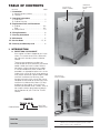
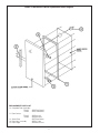
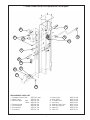
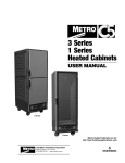
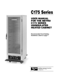
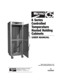
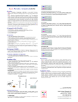
TC90S
TC90B
USER MANUAL
FOR THE METRO
TC90 SERIES
INSULATED
TRANSPORT
CABINET
InterMetro Industries Corporation
Wilkes-Barre, PA 18705
570-825-2741
TABLE OF CONTENTS
SECTION
OPERATING
INSTRUCTIONS
LABEL
LOCATION OF
MODEL NUMBER
PAGE
I. Introduction
A. Identifying Your Cabinet ............................. 1
B. Features ...................................................... 2
▼
II. Operating Instructions
A. Slide Racks ................................................. 2
B. Cabinet Start-Up ......................................... 2
▼
III. Replacement Parts and Procedures
A. Cabinet ....................................................3-6
A . Door .........................................................3-6
B. Control Panel ...........................................7-9
IV. Wiring Schematic ....................................... 10
V. Cleaning Instructions ................................ 11
VI. Maintenance ............................................... 11
VII. Service Notes .......................................15, 16
VIII. Warranty and Warranty Card .................... 12
I. INTRODUCTION
A. IDENTIFYING YOUR CABINET
Your cabinet has been shipped to you in one
carton. The carton contains the cabinet with
the slide racks already in place inside the
cabinet.
There are two component numbers you
should record for future reference: the cabinet
model number and serial number. Refer to
the photos at right to locate these numbers.
It is recommended that these numbers be
recorded in an appropriate place such as the
inside of this manual for easy future reference.
Also, please record the cabinet model number
and serial number on the Warranty Card
found on the back of this manual. Be sure to
complete the remainder of the Warranty Card
and return it to Metro within fifteen (15) days
of delivery of the cabinet. Once you have
located and recorded these numbers, refer to
the sample numbers given below to identify
the components of your TC9OS or TC9OB
cabinet.
LOCATION OF
SERIAL NUMBER
SAMPLE:
Cabinet Series
▼
TC90S OR B
Bun Pans
Steam Pans
Model No.________________________________
NOTE: Please read this manual thoroughly before using your
cabinet. If you should have questions, please contact
Metro customer service department.
Serial No. ________________________________
1
The slide spacing is 25/8" to accommodate lip
loaded pans for TC90S; bottom loaded pans
for TC90B. The following pans may be used:
9 pans — 12" x 20" x 21/4" (TC90S)
9 pans — 12" x 20" x 25/8" (TC90S)
9 pans — 18" x 26" x 1" (TC90B)
B. FEATURES — BOTH MODELS
In order to utilize your cabinet to its full potential, take
a minute to identify the following features which have
been provided for your convenience.
• Cabinet is shipped in one carton.
• Temperature range is 120°F to 180°F.
B. CABINET START-UP
• Analog type thermometer to allow temperature
monitoring when unit is disconnected from power
source.
1. A nine-foot, three-wire grounded lead cord is
supplied fixed to the cabinet. The cord cannot
be separated from the cabinet.
• 15 amp service.
NOTE: Before operating your cabinet be sure to
unwrap the lead cord completely from bracket.
• 3 - 300 watt heating elements.
• Totally insulated with high temp rigid board
fiberglass insulation.
CAUTION: With the POWER switch OFF, plug
the lead cord into a standard grounded 15-amp,
125-VAC receptacle.
• Kick latch for “hands-off” opening.
• Magnetic door latch.
2. Set the thermostat dial to setting 10 = HIGH.
• Adjustable hinges and strike.
3. Snap the POWER switch to ON. The red
POWER light will now glow as will the yellow
indicator light indicating that power is on and
that the heating elements are activated and
heating up.
• Removable slide racks.
• Stainless steel internal liner.
• Closed loop thermal break to reduce heat transfer.
4. Allow the cabinet to PREHEAT FOR
APPROXIMATELY 45 MINUTES. After that time,
the thermostat can be lowered to a setting of
6 or 7. In a room of average temperature
(72°F), this should provide 150°F to 170°F.
Adjustments to the temperature may be made
as necessary.
• Outside shell brushed aluminum.
• Non-marking 5" neoprene casters (two with brakes).
• Side mounted lift handles.
• Adjustable door mounted vent.
NOTE: The POWER (red) light will glow as
soon as the POWER switch is switched ON
and will continue to glow until switched OFF.
The yellow indicator light will go on and off as
the thermostat cycles. If the yellow light is not
illuminated, this indicates that the cabinet has
achieved the preset TEMPERATURE level,
NOT that the unit has been switched OFF.
II. OPERATING INSTRUCTIONS
A. SLIDE RACKS
The slide racks provided with your cabinet
are nickel chrome-plated to insure years of
corrosion-free service. The racks are already
in place when the cabinet is shipped to you.
They can be removed for cleaning by first lifting
up on the rack and then swinging the bottom
towards the center of the cabinet.
It is not necessary at the end of the operating
day to disrupt the temperature setting in order
to turn the unit OFF. By switching the POWER
switch to OFF, the unit is no longer operating.
By switching the POWER switch to ON when
resuming operations, the cabinet will attain the
preset level.
2
III. REPLACEMENT PARTS
AND PROCEDURES
A. CABINET
1. Refer to TC90S/TC90B Series Cabinet Replacement
Parts Diagram to identify the part(s) to be replaced.
2. Refer to TC90S/TC90B Cabinet Replacement
Procedure Chart on pages 5 and 6 for replacement
instructions.
TC90S / TC90B Series Cabinet Replacement Parts Diagram
REPLACEMENT PARTS LIST
1. Heating Element
2. Caster — Without Brake
3. Caster — With Brake
4. Thermometer Bulb Clamp
5. Thermostat Bulb Clamp
6. Vertical Thermal Break
6. Hoz. Thermal Break TC90S
6. Hoz. Thermal Break TC90B
#RPC13-112
#B5DN
#B5DNB
#RPC06-222
#RPC06-221
#RPC06-323
#RPC06-324
#RPC06-324A
7. Slide Rack
7. Slide Rack
8. Star Bushing
9. Cabinet Hinge
9A. Door Hinge Pin
3
TC90S #RPTC90S-RACK
TC90B #RPTC90B-RACK
#RPC06-189
#RPHINGE-4000
#RPF07-050A
TC90S / TC90B Series Cabinet Replacement Parts Diagram
REPLACEMENT PARTS LIST
10. Complete Door Assembly
TC90S
TC90B
11. Door Gasket
TC90S
TC90B
12. Strike Plate
13. Door Vent Assembly
14. Door Hinge
#RPCT90S-300G
#RPCT90B-300G
#RPC06-325
#RPC06-325A
#RPTC90S-3400
#RPC11-206
#RPHINGE-4001
4
TC90S / TC90B SERIES
CABINET REPLACEMENT
PROCEDURE CHART
CAUTION: Before any repair/replacement pf parts, be
certain to disconnect cord from power source.
PARTS TO BE REPLACED
REPLACEMENT PROCEDURE
PARTS TO BE REPLACED
1. Heat Element
1. Remove door and slide racks.
(Refer to Complete Door)
2. Remove control panel. (Refer to
Complete Control Panel)
3. Remove thermostat and
thermometer bulb clamp located
on the inside top front surface.
Remove bushing and then push
both bulbs (long thermostat bulb
first) through the hole located
on the upper left corner of the
cabinet. Be careful not to bend
sharply or kink the capillary tubes.
4. Disconnect the RED & WHITE
wires from the terminal block of
the control panel. (NOTE: Record
the location of the wires so as to
reconnect correctly.)
5. Remove the outer wrapper
fasteners located at the
perimeter of the cabinet and
retain. NOTE: If replacing one or
both of the side elements only, it
is not necessary to remove the
fasteners at the bottom of the
door opening nor the fasteners
located at the underside of the
rear of the cabinet. Remove them
only if the bottom element is to
be replaced.
6. Remove the fasteners holding
the outer wrapper to the chassis
and retain.
7. Carefully lift the outer wrapper
vertically off of the chassis
being careful to feed the RED
& WHITE wires through the
bushing in the wrapper. Note that
the black thermal break strips
located around the perimeter of
the cabinet opening are free to
fall out of position, should this
happen, reposition them when
reinstalling the outer wrapper.
8. Before removing the fasteners
retaining the element covers,
note the position of the RED &
WHITE wires of the element.
Remove the element cover and
damaged element. To replace
the element with part number
RPC13-112, first tape or wire
tie the new element wires to the
existing element wires, then tie a
wire or string to the banded wire
ends and while placing the outer
wrapper over the inner liner,
slowly draw the wires through the
lower starburst bushing located
on the outer wrapper side. Be
certain not to pinch any wires
during assembly of the cabinet.
Once the outer shell is in place,
cut the new wire to the same
length as the existing wires and
then strip the ends of the wires
and attach a UL recognized
spade terminal.
9. Attach the element wires to the
terminal block of the control
panel at the prenoted locations
and reattach the control panel
and door to the cabinet.
2. Caster without
1. Lay cabinet over onto its back
1. Brake
and remove mounting hardware.
2. Replace with part number B5DN.
3. Caster with
1. Lay cabinet over onto its back
1. Brake
and remove mounting hardware.
2. Replace with part number B5DNB.
4. Thermometer
1. Remove clamp and replace with
1. Bulb Clamp
part number RPC06-222.
5. Thermostat
1. Remove clamp and spacer and
1. Bulb Clamp
replace with part number RPC06221 (Clamp), RPC11-129 (Spacer).
6. Thermal Breaks
1. Refer to Heat Element for
procedure. Replace with part
number RPC06-323 for vertical
thermal break. For horizontal
thermal break replace with part
number RPC06-324 for TC90S
RPC06-324A for TC90B.
7. Slide Racks
1. Lift straight up until bottom of
rack clears lower bracket and
swing bottom out. Drop straight
down to clear top brackets.
2. Replace with part number
RPTC90S-RACK (TC90S)
RPTC90B-RACK (TC90B)
8. Star Bushing
1. Remove thermometer and
thermostat bulb clamps and
carefully push the bulbs out
through the grommet being
certain not to bend or kink the
capillary tubes.
2. Pry out the bushing and replace
with part number RPC06-189.
9. Hinges
1. Remove damaged hinge and
replace with part number
RPHINGE-4000. See Complete
Door for adjustment.
9A. Hinge Pin
1. Replace with part number
RPF07-050A.
10. Complete Door
1. Open door and swing open to
180° to clear cabinet hinge pins.
Lift door off hinges.
2. Replace with part number
RPTC90S-300G (TC90S)
RPTC90B-300G (TC90B)
NOTE: Be certain to check door gasket seal is equal all
around door before tightening the hinge screws. When door
is properly adjusted, it will close properly when simply swung
closed. (No hand pressure)
1. Heat Element
1. (continued)
5
REPLACEMENT PROCEDURE
PARTS TO BE REPLACED
REPLACEMENT PROCEDURE
11. Door Gasket
1. Remove door. (Refer to
2.
12. Strike Plate
1.
13. Door Vent
13. Assembly
1.
2.
3.
14. Hinge
1.
2.
3.
Complete Door page 5,
step 10)
Lay complete door on flat
surface (place cardboard or
equivalent down first so as
not to scratch or mark door
surface). Remove fasteners
retaining inner door panel
and vent and retain. Lift
inner panel off and remove
damaged door gasket.
Carefully replace gasket with
part number RPC06-325
for TSC90S; RPC06-325A
for TSC90B. Place inner
panel over new gasket and
fasten. Do not overtighten.
See Complete Door for
adjustment.
Remove damaged strike plate
and replace with part number
RPTC90S-3400.
Remove fasteners retaining
vent.
Remove the wing nut and
vent components.
Replace damaged vent with
part number RPC11-206.
Remove door. (Refer to
Complete Door page 5,
step 10)
Remove damaged hinge and
replace with part number
RPHINGE-4001.
Replace door.
6
1. TC90S / TC90B Control Panel Replacement Parts Diagram
7
6
3
8
9
4
5
2
10
12
13
14
11
15
REPLACEMENT PARTS LIST
1. Complete Control Panel
2. Power Switch
3. Indicator Lights
Red
Yellow
4. Termostat Knob
5. Terminal Block
6. Thermometer
7. Thermostat
8. Power Cord
9. Strain Relief
10. Transport Latch
11. Kick Latch
12. Magnetic Door Latch
13. Kick Latch Spring
14. Cotter Pin
15. Clevis Pin
#RPTC90-4000
#RPC13-375
#RPC13-246
#RPC13-245
#RPC06-313
#RPC13-096
#RPC13-109
#RPC13-113
7
#RPC13-108
#RPC13-110
#RPC09-028
#RPC09-027
#RPC14-041
#RPC10-013
#RPF07-040
#RPF05-017
TC90S / TC90B
CONTROL PANEL
REPLACEMENT
PROCEDURE CHART
CAUTION: Before any repair/replacement pf parts, be
certain to disconnect cord from power source.
PARTS TO BE REPLACED
1. Complete
1. Control Panel
2. Power Switch
PARTS TO BE REPLACED
REPLACEMENT PROCEDURE
1. Open door and remove rack on
control panel side. (Refer to
Heat Element Replacement
page 5, step 7)
2. Place a cardboard sheet down
and lay the cabinet on its back.
Remove the screws holding the
control panel to the chassis.
(On underside of chassis)
3. Stand cabinet up and remove
the two screws holding the
control panel to the cabinet (at
the top of the cabinet).
4. Remove the two clamps
holding the thermostat and the
thermometer to the underside
of the cabinet top and retain.
Uncoil power cord.
5. Carefully lift the control panel
vertically off the outer wrapper
brackets. After the initial
movement, note the notch
in the control panel and the
bracket mounted to the cabinet.
6. With the panel clear of the
brackets, remove the grommet
in the inner wall and push
the two bulbs through the
hole at the cabinet side wall.
(Thermostat bulb first “Longer
Bulb”.)
7. Note and mark RED & WHITE
wire locations and remove the
wires from the terminal block.
8. Disconnect the GREEN ground
wire from the cabinet.
9. It is not necessary to remove any
wires from the new control panel.
10. Replace the complete control
panel with part number
RPTC90-4000.
Refer to Complete Control Panel.
1. Note the location of each wire
connected to the power switch,
marking if necessary. Also note
the orientation of the switch
body of each terminal.
2. Remove wires from switch.
3. Depress tabs on switch body
and push it out through the
control panel.
4. Install new switch part number
RPC13-375.
5. Reconnect wires to correct
terminals.
3. Indicator Lights
3. (Red or Yellow)
4. Thermostat
4. Knob
5. Terminal Block
6. Thermometer
7. Theromstat
8
REPLACEMENT PROCEDURE
Refer to Complete Control Panel.
1. Note the location of each wire
connected to the pilot lights.
Mark them if necessary.
2. Disconnect the pilot wires from
the terminal block.
3. Using a small screwdriver, pry
loose the retaining clip from the
light body. Pull the light and
wires through the control panel.
4. Install new spade terminals part
number RPC13-027 to the wire
ends.
5. Install new pilot light (Red part
number RPC13-246, Yellow part
number RPC13-245).
1. Pull knob from shaft of
thermostat and repIace with
part number RPC06-313.
Refer to Complete Control Panel.
1. Note the location of each wire
connected to the terminal
block and the terminal block
orientation. Mark the wires if
necessary. Disconnect all wires
from the block.
2. Remove damaged block by
removing retaining screws
located at rear of control panel
and retain.
3. Install new speed nuts part
number RPF02-068 into terminal
block and replace block with
part number RPC13-096.
Refer to Complete Control Panel.
1. Remove the screw retaining the
bulb to the inner liner.
2. With control panel disconnected,
remove the grommet on the
upper left inside corner of the
cabinet. Push the thermostat
bulb first, then the thermometer
bulb through the hole in the
cabinet side and out through the
bushing in the outer wrapper.
Replace thermometer with part
number RPC13-109. Carefully
uncoil new tubing and bulb
and feed through the bushing
in the cabinet side. CAUTION:
DO NOT make sharp bends or
kinks in the capillary tubing.
3. Seal the hole around the
capillary tubing in the inside
of the cabinet with a FDA
grade silicone sealant. If inner
grommet is damaged, replace
with part number RPC07-044.
Refer to Complete Control
Panel.
PARTS TO BE REPLACED
8. Power Cord
9. Strain Relief
REPLACEMENT PROCEDURE
1. Remove the screw retaining the
bulb to the inner liner.
2. With control panel
disconnected, remove the
grommet in the cabinet inner
liner and carefully push the
thermostat bulb through
the hole in the cabinet side.
Replace grommet with part
number RPC07-044 and
thermostat with part number
RPC13-113. Attach wires to
correct terminals.
3. Carefully uncoil new tubing
and bulb and feed through the
bushing in the cabinet side.
CAUTION: DO NOT make
sharp bends or kinks in the
capillary tubing.
4. Replace control panel being
careful not to pinch the
capillary. Also, coil the unused
portion of the capillary tube
near the top of the control panel
BEING CAREFUL TO KEEP
THE TUBE CLEAR OF ANY
ELECTRICAL TERMINALS.
5. Seal the hole around the
capillary tubing in the inside of
the cabinet with a FDA grade
silicone sealant.
1. Uncoil cord and remove
complete control panel. Refer
to Complete Control Panel.
2. Remove strain relief.
3. Note and record wire locations
on terminal block and
grounding stud.
4. Remove damaged cord and
replace with part number
RPC13-108.
1. Using pliers, squeeze the strain
relief from the inside and push
it out through the mounting
hole. Replace with part number
RPC13-110.
2. Install new relief onto the
cord, squeeze and insert into
mounting hole. Be certain that
the flats on the relief match the
flats on the hole.
PARTS TO BE REPLACED
REPLACEMENT PROCEDURE
10. Travel Latch
1. Remove control panel. See
Complete Control Panel page
8.
2. Remove hardware retaining
latch and replace with part
number RPC09-028.
1. Remove control panel. Refer to
Complete Control Panel page
8.
2. Remove cotter pin and clevis
pin. Replace kick latch with
part number RPC09-027.
1. Remove control panel. Refer to
Complete Control Panel page 8.
2. Remove old latch by pinching
the top and bottom of the
magnet housing from the inside
of the control panel. Push the
part out through the front.
3. Replace with part number
RPC14-041 by inserting from
front of control panel.
4. Replace control panel.
1. Remove cotter pin.
2. Remove clevis pin.
3. Replace spring with part
number RPC10-013.
1. Replace with part number
RPF07-066.
1. Replace with part number
RPF05-017.
11. Kick Latch
12. Magnetic
13. Door Latch
13. Kick Latch
14. Spring
14. Cotter Pin
15. Clevis Pin
9
10
IV. WIRING SCHEMATIC
2. HEAVIER SOIL
If cleaning has been postponed, solvent
or emulsion type cleaners that can be
applied with bare hands will give excellent
results. Such cleaners are available under
various brand names and detergent
suppliers can recommend materials
appropriate for use on natural and epoxycoated aluminum and stainless steel
interior liner.
V. CLEANING INSTRUCTIONS
ALL MODELS
Your TC90 series cabinet has been listed
by the National Sanitation Foundation (NSF)
which means that it has been designed and
constructed in a way that promotes a sanitary
condition, i.e. sanitary materials and easy
cleanability. To maintain a sanitary condition
and obtain the best cabinet performance, Metro
strongly suggests that the cabinet be thoroughly
cleaned on an adequate regular basis — daily if
necessary.
NOTE: For every cleaning method, best results
are always obtained when the cleaner and
technique are matched to the soil conditions
involved. To ensure using the proper cleaner
for natural and epoxy- coated aluminum
and stainless steel, contact your detergent
representative.
A. REMOVAL OF INTERIOR COMPONENTS
FOR CLEANING
All interior components are removable,
without tools, for thorough, unobstructed
cleaning.
1.
VI. MAINTENANCE
CAUTION
A. CABINET MAINTENANCE—ALL MODELS
AT NO TIME SHOULD THE CABINET
BE WASHED OR FLOODED WITH
WATER OR LIQUID SOLUTION. NEVER
STEAM CLEAN. SEVERE DAMAGE OR
ELECTRICAL HAZARD COULD RESULT.
Your TC90 series cabinet has been designed
to require very little maintenance. With normal
use, cleaning is the only form of maintenance
that need be done on a regular basis.
Keeping the casters free of dirt build-up will
go a long way in prolonging their life.
1. Turn off master switch.
2. Disconnect the unit from its power source.
2.
If your cabinet is rolled over rough surfaces
or transported over-the-road, the various
threaded fasteners, i.e., screws and nuts,
should be periodically inspected and
tightened if necessary, particularly the
transport latch, hinge and caster fasteners.
WARNING
ALLOW THE UNIT TO COOL BEFORE
CLEANING, AS THE INTERIOR OF THE
CABINET MAY BE HOT ENOUGH TO
BURN.
B. CONTROL PANEL MAINTENANCE
3. If necessary, the door may be removed by
simply lifting it from its cabinet-mounted
hinges. Do not place the door against
an object that may scratch the door or
damage the gasket.
The control panel of your cabinet has
also been designed to require very little
maintenance. With normal use, cleaning is
the only form of maintenance that need be
done on a regular basis. No maintenance is
required on the electrical components.
4. The slide racks may be removed by lifting
them from their respective brackets.
5. After cleaning, simply reverse the above
steps to reassemble the cabinet.
B. SPECIFIC CLEANING INSTRUCTIONS
1. Do not immerse the cabinet when
cleaning. Instead, use a damp cloth and a
drying towel. BE SURE TO THOROUGHLY
DRY THE UNIT BEFORE RETURNING IT
TO USE.
C. GENERAL CLEANING INSTRUCTIONS
1. LIGHT SOIL
If routine (daily) cleaning is practiced,
a mild soap and warm water should be
sufficient to keep the unit clean.
11
InterMetro Industries Corporation (hereinafter referred to as “Seller”) warrants to the
12
Thank you for purchasing a Metro Mobile Heated
Cabinet. We are certain you will be more than
satisfied with its quality and performance. Please fill in
the warranty information space below so we may register
your warranty. Also, so that we may learn more
about our customers and hopefully be of continued
service in the future, please take a moment
to fill in the customer information space below.
Thank You
CUT ALONG DOTTED LINE
CUSTOMER INFORMATION
1. Which one of the following best describes your
establishment?
a. ❑ Full Service Restaurant
b. ❑ Fast Food Restaurant
c. ❑ Hotel/Motel
d. ❑ Hospital/Nursing Home
e. ❑ College/University
f. ❑ School
g. ❑ Employee Feeding
h. ❑ Other
WARRANTY INFORMATION:
Cabinet Model No.
Module Serial No.
Slide Rack Model No.
Date Purchased
Customer Name
Address
Phone No.
CUT ALONG DOTTED LINE
For warranty coverage, this card
must be returned to Metro.
FOLD HERE — DO NOT DETACH
2. Please indicate the two product benefits that
were of major interest to you.
a. ❑ Accessibility to controls without opening door.
b. ❑ All components within cabinet removable for
cleaning.
c. ❑ Better control of conditions in cabinet.
d. ❑ Aesthetic quality (styling).
g. ❑ Other (in addition to above two)
13
3. Main factor that led to your decision to
purchase this product?
a. ❑ Product operating and functional features
b. ❑ Overall quality
c. ❑ Price
d. ❑ Availability
e. ❑ Other
4. Three sources that led to the purchase of
this product — in the order of their impact
(1 - being most impact; 3 - being least impact).
a. ❑ Trade Journal Ad
b ❑ Trade Show
c. ❑ Sales Call
d. ❑ Direct Mail
e. ❑ Previous Purchase
f. ❑ Other
STAPLE HERE
STAPLE HERE
STAPLE HERE
FOLD HERE — DO NOT DETACH
NO POSTAGE
NECESSARY
IF MAILED
IN THE
UNITED STATES
BUSINESS REPLY MAIL
FIRST-CLASTAINLESS STEEL
PERMIT NO. 121
WILKES-BARRE, PA
POSTAGE WILL BE PAID BY
INTERMETRO INDUSTRIES CORPORATION
ATTN: CUSTOMER SERVICE
P O BOX A
WILKES-BARRE PA 18705-9968
VII. SERVICE NOTES
15
VII. SERVICE NOTES
16
InterMetro Industries Corporation
North Washington Street, Wilkes-Barre, PA 18705
For Product Information Call: 1-800-992-1776
Visit Our Web Site: www.metro.com
L01-144
Rev. H 10/10
Information and specifications are subject to change
without notice. Please confirm at time of order.