1
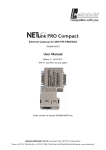
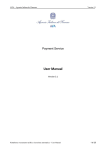
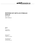
SIGMA ‘INFILINK/DPC’ SCADA SOFTWARE
FOR LIFT STATIONS USER MANUAL
VISIT OUR WEBSITE SIGMACONTROLS.COM
2
INTRODUCTION:
The Sigma Infilink/DPC offers a low-cost graphical interface for lift station SCADA
applications. The software installs on any Windows based PC and communicates with the
pump controller via MODBUS RTU protocol, using hardware, telephone or radio.
.
The Sigma Infilink/DPC Graphical Software provides complete remote monitoring and
control of Sigma Myriad Duplex Pump Controllers.
Graphical Display of: Wet well level
All system alarms
Communication Status
Set Points
Level and pump run trend
Historical trend screens
Speed to VFD’s (if used)
Digital Display of:
Wet well level
Lead/Lag pump order
Alarm history
Communication status
Remote Control of:
Pumps on & off set points
Alarm set points
VFD level set points
VFD speed set points
Level simulation
3
SPECIFICATIONS:
MINIMUM SYSTEM REQUIREMENTS
Pentium 133MHZ CPU
32 MEG RAM
50 MEG free disk space
Display resolution 640 x 480 run mode
FEATURES:
Historical trending, alarming, data logging
E-mail and WEB enabling standard
No maintenance or support fees
All process parameters shown in graphical or numeric format
Full two-way communication with Sigma Myriad device
NSTALLATION:
Both the Infilink and KepServerEx programs must be loaded and registered. The graphics must be
matched to the resolution of the display. A startup sequence must be programmed. Due to this complexity
installation of the software onto the computer is usually done by Sigma Controls.
STARTUP:
Both the Infilink and KepServerEx should be automatically started with windows. If both of these
programs are not running then the graphics will not respond or appear correctly. Reboot or click on these
items on the desktop to restart the graphics. When the software starts it will display the main or
“STATUS” screen KepServerEx runs in the background it may only be visible in the system tray.
COMMUNICATION:
If the computer is not communication with the Myriad controller then the data will not appear in the
appropriate places. Red text will appear indication that the computer is trying to connect and for how
long. When communication is established data will be shown and a graphic of a myriad controller will
appear over the red text.
There are 4 communication methods used to get data from the Myriad.
1) Direct connection is the optimal way but it is only possible when the computer can be put
next to the Myriad at the pump station.
2) Radio is a preferred method because phone line reliability is not an issue.
3) Lease line is good but costly method. This involves a dedicated phone line from the
computer to the Myriad. The phone company controls this line.
4) Dial up is the most readily available. Its biggest drawback is that there is no constant data
stream. Data cannot be logged, nor will alarms be annunciated, unless a phone call is in
session
DIAL UP:
If your system uses dialup, a graphic of a phone will be to the left of the violet ALARM HISTORY button
To make a call, click on this button. A small window will popup. Enter the site’s phone number and click
CALL. Click HANGUP to end the call.
4
Notes on the Main or STATUS screen
• The pump AUTO switches cannot be changed from the computer they only indicate what is in the
field.
• The SPEED TO VFD may show an output when the pump is not running.
• The excel icon only works if Microsoft Excel is loaded on your computer.
• The simulate function will timeout after 30 second of non-use.
• The alternate function only works if alternation is enabled in the Myriad controller.
5
MAIN SCREEN
Indication of field switch in auto
Pump 1 is off
Pump 2 is on
Analog signal being
sent to VFD’s
Link to spreadsheet
application
Links to other screens
Alarm Reset Push
Indicates good
communication with Myriad
Click to override level sensor
with
Indicates pumpLevel
2 is the
lead bar graph
indicating
pump
Indicates pump 1 is the lag
Click to swap lead pumps
Level indication digitally
Alarm
The arrows etc needs to be put back on the status screen. It may be easier to copy it
new from INFILINKINSIDE041405
6
Setpoints Screen
Setpoints Screen
Click on any of the values to bring up a data entry window. Press enter or click OK to accept changes.
The SAVE CHANGES icon must be clicked on after modifying any of the four speed parameters. This
will write the data to a special memory location in the Myriad.
7
Alarms
Upon any alarm, the alarm bell icon will appear, the SILENCE button will appear, the corresponding red
indicator will show which alarm has been tripped, and the ALARM HISTORY feature will display and
record the event. If your computer has speakers, a warning sound will be audible. Click on the SILENCE
button to quiet this sound. The RESET button appears on the status screen, click on the RESET button to
clear alarms in the Myriad. Alarm will only clear if causal condition is no longer in effect.
Alarm History Screen
Alarm History Screen
Details about each alarm and when it occurred is displayed and logged to the hard drive. This info can
only be gathered if the computer is connected to the Myriad at the time of the occurrence. Navigation
buttons are provided to view past events.
8
Trend Screen
Trend Screen
Graphical depiction of the level and VFD speed is recorded. This info can only be gathered if the
computer is connected to the Myriad. It is displayed and logged to the hard drive. Navigation buttons are
provided to view past data.