1
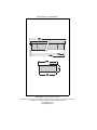
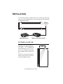
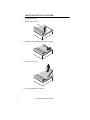
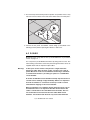
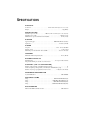
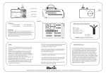
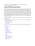
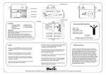
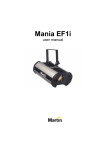
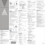
martinarchitectural
user manual
Cyclo 04 Wallwasher
Measurements are in millimeters
1210
1180
1150
290
94
260
© 2003 Martin Professional A/S, Denmark.
All rights reserved. No part of this manual may be reproduced, in any form or by any means, without permission in writing from Martin Professional A/S, Denmark.
Printed in Denmark.
P/N 35000130, Rev A
I NTRODUCTION
Thank you for selecting the Martin Cyclo 04 Wallwasher. The Cyclo Series
is a range of controllable, fluorescent color changers. These fixtures are
designed to be used for cove lighting, perimeter lighting, light walls, behind
semi-transparent materials, or any place where room is restricted.
The Cyclo 04 Wallwasher contains dimmable red, green, blue and white
tubes.
In order to be DMX controlled, the Cyclo 04 Wallwasher fixtures require the
Martin 516 DMX to 0-10 V Converter. The 516 Converter converts DMX to
0-10 V analog output. Additional Cyclos can be daisy-chained for
synchronous dimming. A single 516 Controller can control 4-8 Cyclo groups
individually, each group consisting of one to ten of the same Cyclo model
wired in series (the number of groups depends on the model of Cyclo that is
installed). The member fixtures in each group will react similarly when
controlled.
Cyclo 04 Wallwasher control and power-cables are through-wired for easy
installation.
The Cyclo series offers:
• Controllable RGB color-mixing and/or color temperature
• Bright output
• Precise asymmetrical light distribution
Note:
It is important to read this manual through before you attempt
to install this product.
SAFETY INFORMATION
Warning!
This product is for professional use only. It is not for household
use.
These products present risks of lethal or severe injury due to fire and heat,
electric shock and falls. Read this manual before powering or installing
these fixtures, follow the safety precautions listed below and observe all
warnings in this manual and on the fixtures. If you have questions about how
Cyclo 04 Wallwasher user manual
3
to operate these fixtures safely, please contact your Martin dealer or call the
Martin 24-hour service hotline at +45 70 200 201.
Protect ion from electric shock
• Disconnect the fixtures from AC power before removing or installing a lamp,
fuses, or any part, and when not in use.
• Always ground (earth) the fixtures electrically.
• Use only a source of AC power that complies with local building and
electrical codes and has both overload and ground-fault protection.
• Do not expose the fixtures to rain or moisture.
• Refer all service to a Martin service technician.
Protect ion from burns and f ire
• Provide a minimum clearance of 0.1 meters (4 inches) around the fixture.
• Do not modify the fixture or install other than genuine Martin parts.
• Do not operate the fixture if the ambient temperature (Ta) exceeds 40° C
(104° F).
Protect ion from injury due t o falls
• Verify that all external covers and rigging hardware are securely fastened
• Block access below the work area whenever installing or removing the
fixture.
4
Cyclo 04 Wallwasher user manual
I NSTALLATION
This section describes in general terms how to install the fixture and
connect it to AC and dimmer power. These procedures shall be performed
by qualified professionals.
Mains
200-250V AC
50/60 Hz
516
DMX control device
DMX-to-analog (10V) converter
FIXTURE LOCATION
The fixture can be installed in a
ceiling space of 1200 x 275 mm (+/15
mm).
In
US/Imperial
measurements this is 47 x 11 in. (+/0.5 in.). The installation space should
have a depth of at least 120 mm (4.7
in.)
1/3
The fixture should be installed a
distance away from the wall that is
1/3rd of the height of the wall.
Cyclo 04 Wallwasher user manual
5
INSTALLING THE FIXTURE
To install the fixture:
1 Pull the tube cover off.
2 Slide the reflector towards the tubes to unlock it.
3 Pull the reflector out.
4 Insert the fixture into the ceiling.
6
Cyclo 04 Wallwasher user manual
5 Four metal stays that hold the product in position are provided. Insert a stay
into each of the four holes on the sides of the fixture and screw it into place.:
6 Connect the AC power and dimmer control wiring (as described in the
following sections) before replacing the reflector or tube cover.
AC POWER
Maximum power usage data for the Cyclo 04 Wallwasher is provided in
“Power” on page 12.
You can power Cyclo 04 Wallwasher fixtures by wiring them in series. The
internal wiring of the fixtures carries AC power through the fixture. Holes are
supplied at both ends for input and output cables.
Warning:
In the Cyclo series fixtures incorporate a single electronic
ballast per tube. Each of these “leaks” around 0,2 til 1 mA of
power. Because of this we recommend connecting a maximum
of 30 electronic ballasts (or tubes) per phase on a 30mA HPFI
circuit breaker.
A normal 30 mA HPFI circuit breaker normally trips because of a
current fault or leakage of approximately 20mA. It is important
that the installation is carried out correctly in order to avoid
unintentional tripping of the circuit breaker.
Many installations use common neutral leads in branch circuit
distribution boxes. It is important that the neutral lead in the
cable is connected to the same HPFI circuit breaker, that it is
not connected to the neutral leads from other HPFI circuit
breakers. The neutral lead must be only associated with that
Cyclo 04 Wallwasher user manual
7
specific circuit breaker. Additionally it is important that the
fixtures are connected correctly to the ground (earth) to ensure
that the power leakage is able to run off.
The cable for AC power is passed
through one of the two 5 mm holes
at the end of the fixture. These are
sealed with plastic and you will
need to break a hole in one of the
them.
Use the three terminals not shaded
in grey to connect AC power - L live,
or positive), N (neutral) and ground (or earth).
1
2
3
4
N
L
A clamp connector can be found at
each end of the fixture. One is used
to supply power and dimmer control
to the fixture and the other is used
to send power and dimmer control
onwards to other fixtures in a series.
The number of terminals present on
each clamp connector is dependent
on the Cyclo model.
AC power
connections
Be sure to refer and comply with local standards. Some common AC cable
configurations are:
Wire (EU)
Wire (US)
Pin
Marking
brown
black
live
“L”
blue
white
neutral
“N”
yellow/green
green
ground
If the fixture is being wired in series with other Cyclo 04 Wallwasher fixtures
of the same type, perform these steps at the other end of the fixture to
connect it to the next fixture.
8
Cyclo 04 Wallwasher user manual
DIMMER CONTROL FROM A 516-II DMX
TO 0-10 V CONVERTER
Note:
If you apply power to a Cyclo 04 Wallwasher fixture that is not
connected to a dimmer then it will operate at full power.
The 516-II DMX to 0-10 V Converter has 16 analog outputs for connecting
0-10 V analog devices. For independent control, a Cyclo 04 Wallwasher
requires four outputs.
A maximum of 10 Cyclos (ballasts) of the same model can be wired in
series to the same analog output/s on the 516-II DMX to 0-10 V Converter.
Each Cyclo in the series will mimic the behavior of the others. Do not wire
different Cyclo models in series to the same analog outputs.
This means that a single 516-II DMX to 0-10 V Converter can provide
independent control of up to 4 groups of 10 Cyclo 04 Wallwashers.
Each output on the 516-II DMX to 0-10 V Converter is connected to both a
5-pin DIN socket and the 25-pin D-SUB socket. For the purposes of wiring,
the pin configuration can be found on the rear panel of the 516 controller.
Wiri ng t he 5-pin DIN connector
Use a 5-pin DIN connector to connect the controller to a
series of one of more Cyclo 04 Wallwashers. (The
controller has 4 5-pin DIN outputs enabling control of up
to four parallel series of Cyclo fixtures.)
1
Always connect the ground wire to pin 2, and control 3 5
4
2
leads to the other pins (between 2-4 depending on the
number of tubes in the Cyclo that is being connected). The pin number of
each output is shown on the rear panel. Make a note of which colored leads
are connected to which channels as well as which colored wire is the ground
wire.
Note:
Connections can be tested without a controller by setting all
pins on the converter’s DIP-switch to the off position and then
applying power to the converter and the devices.
Cyclo 04 Wallwasher user manual
9
Connect ing the dimmer cont rol cable to a Cycl o 04
Wall washer f ixt ure
The cable for dimmer control is
passed through one of the two 5
mm holes at the end of the fixture.
These are sealed with plastic and
you will need to break a hole in one
of the them.
3
4
N
L
A clamp connector can be found at
each end of the fixture. One is used
to supply power and dimmer control
to the fixture and the other is used
to send power and dimmer control
onwards to other fixtures in a series.
The number of terminals present on
each clamp connector is dependent
on the Cyclo model.
1
2
Dimmer
connectors
Use the numbered ter minals to
connect dimmer control. (Note that
there are fewer connectors on Cyclo models with fewer than four tubes.)
Connect the ground (earth) lead to the - terminal. Connect the other leads to
the appropriate connectors. Notes that there are two connectors at each
position and that you can use either one of these.
The internal wiring in the fixture carries the dimmer control through the
fixture. Holes are supplied at both ends for input and output cables. If the
fixture is being wired in series with other Cyclo fixtures of the same type,
perform these steps at the other end of the fixture to connect dimmer control
to the next fixture.
Note:
You can simultaneously control dimming on multiple Cyclo
fixtures of the same type by wiring them in series. However,
each analog output from the 516 Converter supplies 20mA. This
means that a maximum of 10 Cyclos (ballasts) in series can be
controlled from each 516 Converter channel. Each ballast
requires 1.5-2 mA.
If you are connecting multiple Cyclo fixtures in series that the
length and diameter of the control (dimmer) cabling must be
dimensioned so that the voltage drop over the cabling is less
than 0.5 volts.
FLUORESCENT TUBES
Removing t ubes
To remove a tube, pull the lamp
cover off, grasp both ends of the
tube and rotate it until it you are
able to lift an end free.
You may need to remove the
outside tubes in order to access
tubes in the middle of the
mount.
It is advisable to replace all the
tubes simultaneously.
Burning in new tubes
In order to obtain the full tube life time, new fluorescent tubes must be
burned in for 100 hundred hours at full power (10 volts).
Identi fying tube posi tions
Tube positions are identified in the Cyclo 04 Wallwasher as follows:
Marking in fixture Marking on tube Color
R
OSRAM 28/60
G
OSRAM 28/66
Green
B
OSRAM 28/67
Blue
Reference illustration
Red
R
None
OSRAM 28/827
OSRAM 28/840
OSRAM 28/860
G
B
2700K white
4000K white
6000K white
CLEANING
We recommend that you clean the fixture with a damp cloth.
SPECIFICATIONS
PHYSICAL
L x W x H. . . . . . . . . . . . . . . . . . . . . . . . . . . . . . 1210 x 290 x 94 mm (47.6 x 11.4 x 3.7 in.)
Weight. . . . . . . . . . . . . . . . . . . . . . . . . . . . . . . . . . . . . . . . . . . . . . . . . . . . . . . . . 9 kg (20 lbs)
INSTALLATION
Installation space (L x W) . . . . . . . . . . . . 1200 x 275 mm +/-15 mm (47 x 11 in. +/-0.5 in.)
Installation space depth . . . . . . . . . . . . . . . . . . . . . . . . . . . . . . . . . . . . . . . . 120 mm (4.7 in.)
Minimum free space around fixture when installed . . . . . . . . . . . . . . . . . . . . 25 mm (1 inch)
SOURCE
Approved lamp type . . . . . . . . . . . . . . . . . . . . . . . . . . . . . . . . OSRAM T5 FH 28 watt tubes
Light source . . . . . . . . . . . . . . . . . . . . . . . . . . . . . . . . . . . . . . . . . . . . . . . .T5 tubes (3x28W)
POWER
AC power . . . . . . . . . . . . . . . . . . . . . . . . . . . . . . . . . . . . . . . . . . . .198 V - 254 V, 50 / 60 Hz
Dimmer control . . . . . . . . . . . . . . . . . . . . . . . . . . . . . . . . . . . . . . . . . . . . . . . , 1-10V control
Maximum power and current @ 230 V / 50 Hz . . . . . . . . . . . . . . . . . . . . .0.56 A / 128 watts
THERMAL
Maximum ambient temperature (Ta) . . . . . . . . . . . . . . . . . . . . . . . . . . . . . . . 40° C (104° F)
DYNAMIC EFFECTS
Dimmable tubes . . . . . . . . . . . . . . . . . . . . . . . . . . . . . . . . . . . . . . Red, green, blue and white
Independent dimming of each tube via 516 Converter
CONTROL (VIA 516 CONVERTER)
Number of independently controllable dimming channels . . . . . . . . . . . . . . . . . . . . . . . . 16
Channels required per independently controlled Cyclo 04 Wallwasher group . . . . . . . . . . 4
Number of Cyclos per group (fixtures wired in series) . . . . . . . . . 1-10 (of the same model)
ORDERING INFORMATION
Cyclo 04 Wallwasher . . . . . . . . . . . . . . . . . . . . . . . . . . . . . . . . . . . . . . . . . . . .P/N 90550030
INCLUDED ITEMS
Lamp. . . . . . . . . . . . . . . . . . . . . . . . . . . . . . . . . . . . . . . . . . . . .OSRAM T5 FH28W/60 (red)
Lamp. . . . . . . . . . . . . . . . . . . . . . . . . . . . . . . . . . . . . . . . . . OSRAM T5 FH 28W/66 (green)
Lamp. . . . . . . . . . . . . . . . . . . . . . . . . . . . . . . . . . . . . . . . . . . .OSRAM T5 FH28W/67 (blue)
Lamp. . . . . . . . . . . . . . . . . . . . . . . . . . . . . . . . . . . . . . . . . .OSRAM T5 FH28W/840 (white)
ACCESSORIES
Martin 516 II DMX to 0-10V Converter . . . . . . . . . . . . . . . . . . . . . . . . . . . . .P/N 90758225
www.martin-architectural.com • Olof Palmes Allé 18 • 8200 Aarhus N • Denmark
Tel: +45 8740 0000 • Fax +45 8740 0010