1
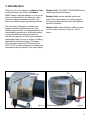
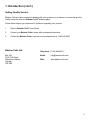
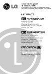
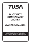
BAIEKUR COILS Ltd.
PRE WELD HEATING COILS
USER MANUAL
110/120 Volt - MODELS 400/1200
220/230 Volt - MODELS 400/1200E
Feb. 15, 2014
Company contact details:
Baiekur Coils Ltd.
Box 264 5312 52nd A Street Wabamun Alberta Canada T0E 2K0
Email: [email protected]
Baieker Coils Ltd. declares that their:
Electrical Resistance Heaters
listed as the following models
400, 600, 800, 1000, 1200,
400E, 600E, 800E, 1000E, 1200E
on behalf of Baiekur Coils Ltd.
Original instructions.
The A weighted emission sound pressure level at work station does not exceed 70
dB(A).
2
INDEX
SECTIONPAGE
1. Introduction
2
2. Limited Warranty
4
3. Quick Reference
5
4. Important Safety Rules
6
5. Operation
9
6. Service
12
7. Replacement Parts
12
8. Specifications
13
1
1. Introduction
Thank you for your purchase of a Baiekur Coils®
Heater. We know you will find the Baiekur
Coils® Heater a valuable addition to your tool kit
and you will benefit from the efficiency, safety
and enviromental advantages that are to be
found over traditional pipe pre-heating methods.
The coil heater is designed to preheat new
piping to specified temperature prior to the
welding sequence (this is usuallyspecified by the
owner/welding procedure/ or the boilers branch,
or any other authority that has jurisdiction).
Also all insitu piping in a H2S service requires a
hydrocarbon bake out prior to cutting or welding
(specified by authority in place). The heater
coil in this case expels the H2S molecules at
600ºF (315ºC) so that cutting and or welding can
commence without fractures to the parent metal.
Baiekur Coils® offer SAFTY ADVANTAGES over
traditional pre-heat techniques.
Baiekur Coils® can be installed quickly and
easily. The coil provides even heat throughout
the weld joint and provides better weld platform
as heat is localized.
Baiekur Coils® offers different models and may
not be exactly as shown in Figures 1 and 2
below.
Pin
Thermostat
Figure 1
Plug Receptical
Figure 2
2
1. Introduction (con’t.)
Getting Quality Service:
Baiekur Coils provide a process for dealing with your questions or problems to ensure that product
quality continues with your Baiekur Coils® dealer support.
Follow these steps to get responses to questions regarding your product:
1.
Refer to Baiekur Coils® User Guide
2.
Contact your Baiekur Coils® dealer with unanswered questions
3.
Contact the Baiekur Coils® customer service department at 1 866 942 6457
Baiekur Coils Ltd.
Telephone: (1 866 942 8657)
Box 264
5312-52 A Street
Wabamum, Alberta
Canada
T0E 2K0
Email:
[email protected]
Web:
www.baiekurcoils.com
3
2. Limited Warranty
EXCLUSION OF REMEDIES
Baiekur Coils® warrants to the original
purchaser that each new Baiekur Coils® is free
from defects in material and workmanship and
agrees to repair or replace, under this warranty,
any defective heater coil for 90 days from the
original date of purchase as the exclusive
remedy. The essential purpose of this warranty
is to provide the purchaser with a properly
functioning coil. Any action for breach of any
terms of this product shall be commenced within
one year from the date of breach. This warranty
is not transferable.
In no event will an authorized dealer,
Baiekur Coils®, or any company affiliated with
Baiekur Coils®, be liable for any consequential
damages or injuries, including but not limited to,
loss of profits, rental or substitute equipment,
other commercial or personal loss, personal
injuries or property damages arising from a result
of a fundamental breach, breach of a
fundamental term, or any use, any handling, or
any maintenance of the Baiekur Coils®.
SECURING WARRANTY
No Dealer Or Agent Warranty
To secure warranty service the purchaser must
(1) report the Equipment defect to an authorized
dealer and request warranty service within the
applicable 90 Day Warranty Period (2) present
evidence of the warranty start date with valid
proof of purchase and (3) make heater coil
available to authorized dealer to repair or replace
for a reasonable amount of time.
The seller has no authority to make any
representation or promise on behalf of
Baiekur Coils® or to modify the terms of
limitations of this warranty in any way.
DISCLAIMER OF ALL IMPLIED WARRANTIES
Baiekur Coils® makes no implied warranties or
statutory condition or warranties of
merchantability or fitness for particular purpose
whether pursuant to the Sale Goods Act, the
Uniform Commercial Code, the commercial code
of any Province, state or territory, or any other
statute of any Province, state or territory.
No Representation or Condition.
To the extent permitted by law, Baiekur Coils®
nor any company affiliated with it makes any
warranty, representation, condition, or promise,
expressed or implied, verbal or otherwise, as to
the quality, performance or freedom from defect
of the coil.
No Warranty Of Title
Baiekur Coils® does not warrant that the
purchaser has any right to convey the title of
purchased coils.
4
3. Quick References
IMPORTANT
This symbol alerts you to potential hazards
that can kill or injure either you or others.
DANGER
Indicates a danger concerning operations
that if not performed properly will lead to
death or injury to persons. In order to use
the equipment safetly always pay attention
to these dangers.
WARNING
Indicates a warning concerning operations
that if not performed correctly could lead to
death or injury to persons. In order to use
the equipment safetly always pay attention
to these warnings.
CAUTION
Indicates a caution concerning operations that
if not performed correctly could lead to
moderate to minor injuries or property
damage. In order to use the equipment
safetly always pay attention to these cautions.
5
4. Important Safety Rules
1.
4.
CAUTION
IMPORTANT
Read ALL instructions in the
user’s manual before using
the heater coil.
2.
Unit will become hot on the outside
(150º F/66º C) when in use. Always wear
proper PPE when handling heater coil.
CAUTION
HOT SURFACE
Burn
Hazard
Do NOT use the coil as a heating
element for anything other than the perscribed
purpose.
5.
CAUTION
Do NOT immerse in water or any other liquid
or operate in wet conditions.
Contact with skin may cause
burns.
DO NOT TOUCH
3.
Do not operate in gaseous or hazardous conditions.
6.
Do not operate in gaseous or hazardous conditions.
DANGER
Fire
Hazard
The coil is not electrically
explosion proof. In gaseous or
hazardous enviroments, use
of electrical equipment could
result in fire or explosion.
CAUTION
Do NOT plug coil in when in
wet conditions.
Shock
Risk
6
7.
CAUTION
The coil plug must be connected to a properly grounded power cord. Ensure that the
power cord is in good condition. When using
a power cord ensure it is heavy enough to
carry the current the coil will draw. An undersized cord will cause a drop in the line
voltage.
A minimum 12 gauge or equivalent
“industrial” power cord with hard plastic
connectors is recommended.
To avoid damage or coil failure the welder
must not arc the electrode on the coil.
An improper or poorly grounded ground cable
connection that is further from the heater than
the length of the power supply cord to the coil
will cause the welder to ground through the
heater coil.
This will cause the coils internal ground wiring to burn out and result in a non warrantable
failure of the heating coil.
POWER CORD RECOMMENDATIONS
Type Of Power Cord
Type Of Cord Plug
Type Of Cord Plugs Material
Minimum Wire Gauge (AWG)
Maximum Cord Length
110 Volt
220 Volt
Industrial*
NEMA 5-15
Hard Plastic
12 Ga.
100 ft. (30 M)
Industrial*
CEE 7/7 EUI-16P
Hard Plastic
12 Ga.
100 ft. (30 M)
Coil Voltage
110/120
220/230
Hertz 50/6050/60
Watts 15001500
Max. Coil Amp.
15
6.5
* Residential cords with soft rubber plugs can overheat and fuse to the coils.
Fig. 3
8.
CAUTION
Always disconnect from power source before
removing coil or setting it in a new
location. Also, disconnect from the power
source prior to cleaning.
CAUTION
To prevent coil damage be sure ground cable
is properly grounded and closer to coil than
length of coil power cord. Do not arc welding
electrode on coil housing.
7
9.
12.
CAUTION
IMPORTANT
Coils are controlled by thermostat only. There
is no ON/OFF switch.
10.
IMPORTANT
When transporting or storing keep unit dry
and safe from damage.
11.
Make sure unit is secured properly on pipe
priot to releasing it. Use care in handling
heater coil at elevation that you don’t drop unit
on someone or on equipment. Do not drop,
hit or abuse the coil. Do not operate coil if it
is damaged or malfunctioning. This includes,
but is not limited to damage or dents to the
outer cover or inner diameter surface of the
ceramics. Report any damage to your safety
representative and/or supervisor for immediate
removal from service. Return the coil to an authorized dealer for inspection prior to reusing.
13.
WARNING
CAUTION
Make sure the power cord does not touch the
heater other than at the plug. Secure power
cord to something other than the coil or pipe
to prevent burning of the cord. Make sure the
cord does not present a tripping
hazard.
Shock
Risk
Damage to internal diameter
ceramics may expose bare
wire and cause an electrical
short.
14.
WARNING
Replace all safety decals that are not in place
and/or damaged. Contact your authorized
dealer for replacement decals.
8
5. Operation
Start Up
1.
4.
Open coil by pulling the latch pin. (see figure 4).
IMPORTANT
Read ALL instructions in the
user’s manual before using
the heater coil.
2.
Inspect heater coil for damage before using.
WARNING
Shock
Risk
3.
Damage to internal diameter
ceramics may expose bare
wire and cause an electrical
short.
Inspect area for combustibles, gaseous or hazardous materials, and ensure the work area is dry.
Latch Pin
5.
Fig. 4
Fit coil over pipe. Place units as shown in fig. 5 with plugs at the 3 o’clock position. (NOTE: use proper heater coil for pipe diameter being worked on).
Pipe
DANGER
Fire
Hazard
The coil is not electrically
explosion proof. In gaseous or
hazardous enviroments, use
of electrical equipment could
result in fire or explosion.
Coils
Fig. 5
9
5A.
or models 800,1000,and 1200 orientate
F
coil so arrow located on outer shell by
handle points towards joint to be heated.
7.Set thermostat setting prior to plugging in
coils. Dial on thermostat is for guidance
only as desired temperature setting will
vary with ambient temperature. Adjust
temperature by using a standard insulated
screw driver. Turn clockwise to increase
temperature, turn counter clockwise to
reduce temperature.
(see fig. 7).
Fig. 5A
6.
Thermostat
ecure unit in place by reattaching pin in S
latch.
CAUTION
DO NOT leave units at elevation until latched,
due to potential of heater being jarred and
falling on someone or equipment. (fig. 6)
Fig. 7
Reattach Pin
8.Install all monitoring devices such as data
loggers, chart recorders, or any other
devices that may be required before
plugging in power source.
9.
CAUTION
Fig. 6
Efficiency Note: Installing coils on
several joints at one time will reduce waiting time
and maximize number of joints welded per day.
Shock
Risk
Use care when installing power
cord. Always install coil end
connection first ensuring it is in
the appropriate condition, the
right size (see figure 3), does
not present a tripping hazard
nor does it touch the pipe being
welded, and is not in contact
with the heater coil other than at
the plug.
10
10.110 Volt When conditions are met and
your safety representative has reviewed all
safety requirements, plug in the power cord
to a properly grounded power source 110
volts, 15 amp service (see fig. 3 for proper
cord sizing).
230 Volt When conditions are met and
your safety representative has reviewed
all safety requirements, plug in the power
cord to a properly grounded power source
220/230 volts, 6.5 amp service (see fig. 3
for proper cord sizing).
CAUTION
12.
After desired temperature is achieved and
has been approved by Quality Assurance,
you can begin to weld. The coil can easily
be slid to give you the required access
room for welding.
Note - use anti splatter spray or paste on
outside shell of coil to avoid splatter sticking
to stainless.
When Required Work Is Complete
1.
Unplug power cord from power source.
2.Allow a cool off period until it is safe to
remone the coil.
CAUTION
The heater is instantly on when plugged into a
power source, as there is no On/Off switch.
Maximum internal temperature is
600ºF/315ºC.
11.
After 15 minutes check the pipe
temperature with temperature sticks or
other devices mentioned in section 8.
Adjust thermostat up (clockwise) or down
(counter clockwise) to achieve desired
temperature using an insulated standard
flat screw driver.
Burn
Hazard
Use proper PPE when
handling the coil.
3.Remove pin from the latch and open the
heater coil (fig.8)
CAUTION
To prevent coil damage be sure ground cable
is properly grounded and closer to coil than
length of coil power cord. Do not arc welding
electrode on coil housing.
Fig. 8
11
4.
Remove unit from pipe.
7. Replacement Parts
5.
arefully relocate heater coil to next
C
desired weld location and repeat the start
up procedure.
Latch pins and decals are available from an
authorized Dealer.
6.
hen finished with the unit store in a dry
W
protected location.
6. Servicing
Clean outside casing with dry cloth.
Note - use anti splatter spray or paste on
outside shell of coil to avoid splatter sticking
to stainless
Clean inside surface with dry cloth.
Inspect for any damage before and after each
use. Report any damage to your safety
representative or supervisor for immediate
removal from service. Coils should be returned to
an authorized servicing dealer
WARNING
Shock
Risk
Damage to internal diameter
ceramics may expose bare
wire and cause an electrical
short.
12
8. Specifications
110/120 Volt Coils
Std. Pipe Dia. Model No. Voltage (1) Hertz Watts Amp. Plug Type
Max. Inside Temp. Time to Max. Temp (1) Adjustable Thermostat Thermostat Accuracy Coil Wall Thickness Outside Dia. Width Weight 4
400 110 / 120 50/60 Cycle 1500 15 NEMA 5-15
600°F (315°C)
20 min. Standard +/- 2.5 F° 1.75’’(45 mm)
7.5”(191 mm)
6” (150 mm)
6lbs (2.7 kg)
6
600 110 / 120 50/60 Cycle 1500 15 NEMA 5-15
600°F (315°C)
20 min. Standard +/- 2.5 F° 1.75’’(45 mm)
9.5’’(241 mm)
6” (150 mm)
6.5lbs (2.9 kg)
8
800 110 / 120 50/60 Cycle 1500 15 NEMA 5-15
600°F (315°C)
20 min. Standard +/- 2.5 F° 1.75’’(45 mm)
11.5’’(292 mm)
6” (150 mm)
7lbs (3.2 kg)
10 1000 110 / 120 50/60 Cycle 1500 15 NEMA 5-15
600°F (315°C)
20 min. Standard +/- 2.5 F° 1.75’’(45 mm)
13.5’’(343 mm)
6” (150 mm)
7.5lbs (3.4 kg)
12
1200 110 / 120
50/60 Cycle
1500
15 NEMA 5-15
600°F (315°C)
20 min.
Standard
+/- 2.5 F° 1.75’’(45 mm)
15.5’’(394mm)
6” (150 mm)
8lbs (3.6 kg) 4
400E
220/230 50/60 Cycle 1500 6.5 6
600E 220/230 50/60 Cycle 1500 6.5 8
800E 220/230 50/60 Cycle 1500 6.5 10 1000E 220/230 50/60 Cycle 1500 6.5 12
1200E 220/230
50/60 Cycle
1500
6.5 220/230 Volt Coils
Std. Pipe Dia. Model No. Voltage (1) Hertz Watts Amp. Plug Type
Max. Inside Temp. Time to Max. Temp (1) Adjustable Thermostat Thermostat Accuracy Coil Wall Thickness Outside Dia. Width Weight CEE 7/7 EUI-16P CEE 7/7 EUI-16P CEE 7/7 EUI-16P CEE 7/7 EUI-16P
600°F (315°C)
20 min. Standard +/- 2.5 F° 1.75’’(45 mm)
7.5”(191 mm)
6” (150 mm)
6lbs (2.7 kg)
600°F (315°C)
20 min. Standard +/- 2.5 F° 1.75’’(45 mm)
9.5’’(241 mm)
6” (150 mm)
6.5lbs (2.9 kg)
600°F (315°C)
20 min. Standard +/- 2.5 F° 1.75’’(45 mm)
11.5’’(292 mm)
6” (150 mm)
7lbs (3.2 kg)
600°F (315°C)
20 min. Standard +/- 2.5 F° 1.75’’(45 mm)
13.5’’(343 mm)
6” (150 mm)
7.5lbs (3.4 kg)
CEE 7/7 EUI-16P
600°F (315°C)
20 min.
Standard
+/- 2.5 F° 1.75’’(45 mm)
15.5’’(394mm)
6” (150 mm)
8lbs (3.6 kg) (1) Based on schedule 40 pipe at an ambient temperature of 70°F (21°C)
13