1
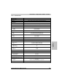
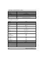
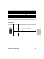
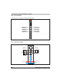
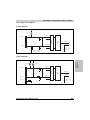
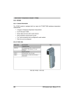
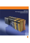
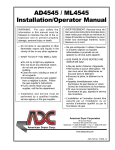
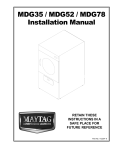
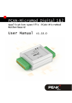
X20 module • Temperature modules • AT2222 22.2 AT2222 22.2.1 General information The AT2222 module is equipped with two inputs for PT100/PT1000 resistance temperature measurement. The AT2222 is designed for the X20 6-pin terminal blocks. If needed (e. g. for logistical reasons), the 12-pin terminal block can also be used. • 2 inputs for resistance temperature measurement • For PT100 and PT1000 • Sensor type can be be set for each channel • Direct resistance measurement as well • 2 or 3 wire connection can be configured for each module • Filter time can be configured 22.2.2 Order data Model number Short description Figure Temperature module X20AT2222 X20 temperature input module, 2 resistance measurement inputs, PT100, PT1000, resolution 0.1 K, 3-wire connections Required accessories X20TB06 X20 terminal block, 6-pin, 24 V coded X20TB12 X20 terminal block, 12-pin, 24 V coded X20BM11 X20 bus module, 24 V coded, internal I/O supply is interconnected Table 525: AT2222 - Order data 848 X20 System User's Manual V 2.10 X20 module • Temperature modules • AT2222 22.2.3 Technical data Product ID AT2222 Short description I/O module 2 inputs for PT100 or PT1000 resistance temperature measurement Temperature inputs - Resistance measurement Input Resistance measurement with constant current supply for 2 or 3-wire connections Digital converter resolution 16-bit Filter time Configurable between 1 ms and 66.7 ms Conversion time 1 channel 2 channels 20 ms at 50 Hz filter 80 ms at 50 Hz filter Output format INT or UINT for resistance measurement Maximum error at 25°C Gain Offset 0.037%, based on the current resistance value 0.0015%, based on the entire resistance range Sensor PT100 PT1000 Can be set per channel -200°C to +850°C -200°C to +850°C 0.1 to 4500 0.05 to 2250 Resistance measurement range General information Status indicators I/O function per channel, operating state, module status Diagnostics Module run/error Inputs Electrical isolation Channel - Bus Channel - Channel Chapter 4 X20 module Yes, with status LED and software status Yes, with status LED and software status Yes No Power consumption Bus I/O internal 0.01 W 1.1 W Certification CE, C-UL-US, GOST-R Operating conditions Operating temperature Horizontal installation Vertical installation 0°C to +55°C 0°C to +50°C Relative humidity 5 to 95%, non-condensing Mounting orientation Horizontal or vertical Installation at altitudes above sea level 0 - 2000 m >2000 m No derating Reduction of ambient temperature by 0.5°C per 100 m Protection type IP20 Table 526: AT2222 - Technical data X20 System User's Manual V 2.10 849 X20 module • Temperature modules • AT2222 Product ID AT2222 Storage and transport conditions Temperature -25°C to +70°C Relative humidity 5 to 95%, non-condensing Mechanical characteristics Spacing 12.5 +0.2 mm Comment Order terminal block 1x X20TB06 or X20TB12 separately Order bus module 1x X20BM11 separately Table 526: AT2222 - Technical data (cont.) 22.2.4 Additional technical data Product ID AT2222 Temperature inputs - Resistance measurement Sensor standard IEC/EN 60751 Temperature sensor resolution PT100 PT1000 1 LSB = 0.1°C 1 LSB = 0.1°C Resistance measurement resolution G=1 G=2 0.1 0.05 Temperature sensor standardization PT100 PT1000 -200.0°C to +850.0°C -200.0°C to +850.0°C Standardized value range for resistance measurement G=1 G=2 0.1 to 4500.0 0.05 to 2250.0 Temperature measurement monitoring Open inputs Wire break Below lower range limit Above upper range limit General error $7FFF $7FFF $8001 $7FFF $8000 Resistance measurement monitoring Open inputs Wire break Above upper range limit General error $FFFF $FFFF $FFFF $FFFF Conversion method Linearization method Reference Measuring current Permitted input signal Input filter Maximum gain drift Sigma Delta Internal 4530 ±0.1% 250 µA ±1.25% Short-term max. ±30 V Low pass 1st order / cut-off frequency 500 Hz 0.004%/°C, based on the current resistance measurement Table 527: AT2222 - Additional technical data 850 X20 System User's Manual V 2.10 X20 module • Temperature modules • AT2222 Product ID AT2222 Maximum offset drift 0.00015%/°C, based on the entire resistance measurement range Common-mode rejection DC 50 Hz >95 dB >80 dB Synchronized zone >0.7 V Cross-talk between channels >93 dB Non-linearity <0.0010%, based on the entire resistance range Isolation voltage betw. channel and bus 500 Veff General information B&R ID code $1BA6 Table 527: AT2222 - Additional technical data (cont.) Figure LED Color Status Description r Green Off Module supply not connected Single flash Reset mode Blinking Preoperational mode On RUN mode e Red Off Module supply not connected or everything is OK On Error or reset state Single flash Warning/error for an I/O channel. Overflow or underflow of the analog inputs. e+r Steady red / single green flash Invalid firmware 1-2 Green Off The input is switched off Blinking Overflow, underflow or broken connection On The analog/digital converter is running, value is OK Table 528: AT2222 - Status indicators X20 System User's Manual V 2.10 851 Chapter 4 X20 module 22.2.5 Status LEDs X20 module • Temperature modules • AT2222 22.2.6 Pin assignments X20 AT 2222 Channels that are not being used should be deactivated. r e 1 2 Sensor + 1 Sensor + 2 Sense - 1 Sense - 2 Sensor - 1 Sensor - 2 Figure 395: AT2222 - Pin assignments 22.2.7 Connection example + _ AT 2-wire connection + _ Sensor 2 Sensor 1 3-wire connection _ +24 VDC GND +24 VDC GND Figure 396: AT2222 - Connection example 852 X20 System User's Manual V 2.10 X20 module • Temperature modules • AT2222 22.2.8 Input circuit diagram 2-line connection 250 µA Channel 1 Sensor + x Multiplexer Channel 2 A/D converter Input value I/O status Channel1 Sense - x Channel 2 LED (green) Switch closed when 2-wire connection Figure 397: AT2222 - Input circuit diagram - 2-wire connection 250 µA Chapter 4 X20 module 3-line connection 250 µA Channel 1 Sensor + x Multiplexer Channel 2 A/D converter Channel 1 Input value I/O status Sense - x Channel 2 PTC LED (green) Sensor - x Figure 398: AT2222 - Input circuit diagram - 3-wire connection X20 System User's Manual V 2.10 853 X20 module • Temperature modules • AT2222 22.2.9 Analog inputs The converted analog values are output by the module in the registers. Different resistance or temperature measurements will result in different value ranges and data types. 22.2.10 Timing setting The timing setting for data acquisition is made using the converter hardware. All switched on inputs are converted during each conversion cycle. 22.2.11 Conversion time The conversion time for the channels depends on their use. For the formulas listed in the table, 'n' corresponds to the number of channels that are switched on. Channel uses Conversion time 1 channel 1 FilterTime n channels with the same sensor type n 20ms + FilterTime n channels with different sensor types n 20ms + 2 FilterTime 22.2.12 Reduced refresh time If an input is not necessary, it can be switched off, thereby reducing the refresh time. Inputs can also be only temporarily switched off. The time saved is equal to: TimeSavings = 2 20ms + FilterTime The filter time is the conversion time for the remaining channels. Examples The inputs are filtered using a 60 Hz filter. Example 1 Switched on inputs Conversion time 854 Example 2 1 1-2 16.7 ms 73.4 ms X20 System User's Manual V 2.10 X20 module • Temperature modules • AT2222 22.2.13 Input filter The filter time for all analog inputs is defined using the input filter parameter. Value Filter Filter time Digital converter resolution 0 15 Hz 66.7 ms 16-bit 1 25 Hz 40 ms 16-bit 2 30 Hz 33.3 ms 16-bit 3 50 Hz 20 ms 16-bit 4 60 Hz 16.7 ms 16-bit 5 100 Hz 10 ms 16-bit 6 500 Hz 2 ms 16-bit 7 1000 Hz 1 ms 16-bit 22.2.14 Sensor type and channel deactivation The module is designed for temperature and resistance measurement. The sensor type must be specified because of the different adjustment values for temperature and resistance. The default setting for all channels is ON. To save time, individual channels can be switched off (see section 22.2.12 "Reduced refresh time" on page 854). Input signal 0 Reserved 1 Reserved 2 Sensor type PT100 3 Sensor type PT1000 4 Reserved 5 Resistance measurement 0.1 to 4500 6 Resistance measurement 0.05 to 2250 7 Channel turned off Chapter 4 X20 module Code 22.2.15 Input status The module's inputs are monitored. A change in the monitoring status generates an error message. Code 0 Channel x No error 1 Below lower limit value 2 Above upper limit value 3 Wire break X20 System User's Manual V 2.10 855 X20 module • Temperature modules • AT2222 22.2.16 "StatusInput01" register Bit Description 0-1 Channel 1: 00 ... No error 01 ... Below lower limit value 10 ... Above upper limit value 11 ... Wire break 2-3 Channel 2: 00 ... No error 01 ... Below lower limit value 10 ... Above upper limit value 11 ... Wire break 4-7 0 In addition to the status info, the error type also sets the analog value to the following values: Error type Temperature measurement Resistance measurement Digital value for error Digital value for error Wire break +32767 ($7FFF) 65535 ($FFFF) Above upper limit value +32767 ($7FFF) 65535 ($FFFF) Below lower limit value -32767 ($8001) 0 ($0000) Invalid value -32768 ($8000) 65535 ($FFFF) 22.2.17 IOCyclicCounter The cyclic counter increases after all input data have been updated. 22.2.18 B&R ID code Code for module identification ($1BA6). 22.2.19 Minimum cycle time The minimum cycle time is the minimum time needed for the bus cycle to be shut down without a communication error or malfunction occurring. It should be noted that very fast cycles reduce the idle time needed for handling monitoring, diagnostics and acyclic commands. Minimum cycle time In each operating mode 856 100 µs X20 System User's Manual V 2.10 X20 module • Temperature modules • AT2222 22.2.20 Minimum I/O update time The minimum I/O update time refers to the minimum time it takes for the bus cycle to shut down, so that in each cycle an I/O update takes place. Minimum I/O update time Equal to the filter time 2 inputs 2 20ms + FilterTime Chapter 4 X20 module 1 input X20 System User's Manual V 2.10 857