1
SAM Technology
Confidential
February 6, 2004
Using the BioCalibration (Signal Check) to Determine Correct
Electrode Placement
At the beginning of each SWMT session, after the SWMT program checks the electrode impedances
and calibrates the channel gains, the EEG traces are displayed, and the technician is instructed to have
the subject blink, look left, look right, then close the eyes. The eye acts like a battery: the cornea is
positive relative to the retina. Changes in the distribution of this charge relative to the EEG electrodes
will result in large, predictable potential differences across the head. Incorrect electrode placement
may produce large eye artifacts in unexpected channels. Such occurrences should alert you to
connection errors in the SWMT jack box.
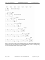
This section first demonstrates the predictable eye blink and eye movement signals you should see
with a relaxed subject, with electrodes properly placed on the head and plugged into the appropriate
jacks in the SWMT jack box. Then some examples of mismappings in the jack box are provided to
show the pattern of activity associated with these errors. Finally, a simple electrode tap test is
described that will allow you to be certain of proper electrode mapping. This test should be performed
for all SWMT electrodes during the first biocal of the day to ensure that all electrodes are placed in
the proper positions. It should be repeated during each subsequent SWMT for the subset electrodes
that have been unplugged from the SWMT jack box since the prior session. This procedure is
explained in more detail in the last section of this document.
Correct Electrode Connections
Step One - Ask the Patient to Blink
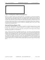
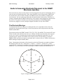
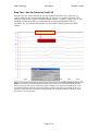
During a blink, the eyeballs roll upward, producing a large positive deflection on electrodes
above the eye, as noted in Figure 2. The amplitude of the blink artifact decreases rapidly with
distance from the eye. Therefore, when you ask the patient to blink, you should see large blink
artifacts on FP1 and FP2. There should be similar, but smaller artifacts on the frontal channels
(F3, FZ, and F4). The blink artifact on CZ should be even smaller. Blink artifacts will be the
smallest and least visible on the parietal channels (P3, P4, POZ). If the blink is small, the blink
artifact may not be visible at all on these channels.
Because blink amplitude decreases with distance from the eyes, the eye blink artifact on
more posterior channels will never be larger than the blink artifact on more anterior
channels, unless the electrodes are mismapped in the jack box. So in this step, make sure that
the amplitude of the blink artifact decreases regularly from frontal to central to parietal. The
magnitude of the blink artifact should be roughly equal on the three frontal channels since they
are located roughly the same distance from the eyes. Similarly, the magnitude of the blink artifact
on P3 and P4 should be roughly equal to each other (and much smaller than the blink on the
frontal channels).
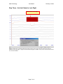
Also note that with correct electrode placement, there should be very little activity on the
horizontal eye channel, BPF9 when the patient blinks. If the horizontal eye electrodes are
placed properly on the face (1 cm lateral and 1 cm below each eye), the blink will produce the
same activity on both channels. Since the left eye electrode is referred to the right eye electrode,
the blink is canceled and will not appear on the BPF9 trace (remember that the traces that appear
on the screen show the difference in electrical potential between the active electrode and the
Page 4 of 16