1
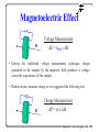
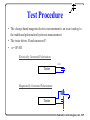
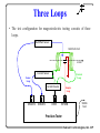
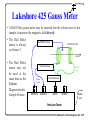
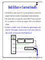
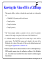
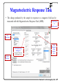
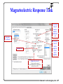
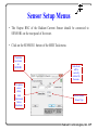
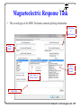
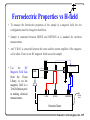
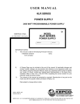
Magnetoelectric Response User Manual Joe T. Evans, Scott Chapman, Jr. Radiant Technologies, Inc. May 20, 2013 Radi ant Techn olo gies, Inc. Summary • Magnetoelectric effect • Test Configuration • Current Loop • Sample Loop • Sensor Loop • Test Execution Radi ant Techn olo gies, Inc. Magnetoelectric Effect V H Voltage Measurement E = ME x H • During the traditional voltage measurement technique, charge generated in the sample by the magnetic field produces a voltage across the capacitance of the sample. • Radiant testers measure charge so we suggested the following test: Q H Charge Measurement P = x H Radi ant Techn olo gies, Inc. Test Procedure • The charge-based magneto-electric measurement is an exact analog to the traditional polarization hysteresis measurement. • The tester drives H and measures P. • = P/H. Electrically Generated Polarization: volts Tester Magnetically Generated Polarization: Tester H Radi ant Techn olo gies, Inc. Magnetoelectric Test Configuration 1. The tester DRIVE output causes a current source to force current through the Helmholtz coil. 2. The Helmholtz coil generates a magnetic field, stimulating the sample. 3. The RETURN input of the Precision tester counts the electrons produced by the sample under magnetic stimulation. 4. The Current Sensor determines the current through the Helmholtz coil from which the magnetic field can be calculated. Helmholtz Coil H-field Current Sensor Current Source SENSOR 1 DRIVE RETURN USB to host Precision Multiferroic Radi ant Techn olo gies, Inc. Helmholtz Coil • A Helmholtz coil consists of two co-axial identical wire coils separated by the radius of the coils. • The magnetic field around the volume occupied by the Helmholtz coil is complex but is easy to calculate in the exact center of the structure. • The equation describing the magnetic field at the center point of the axis between the two coils is B = 0.716o x NI/R where N = the number of turns of each coil I = the current through the coils R = the radius of the coils and the separation between the coils. Radi ant Techn olo gies, Inc. Three Loops • The test configuration for magnetoelectric testing consists of three loops. Hall Effect Sensor Helmholtz Coil H-field Current Sensor Current Loop Sensor Loop Current Source SENSOR 2 SENSOR 1 DRIVE Sample Loop RETURN USB to host Precision Tester Radi ant Techn olo gies, Inc. Current Loop • The current loop consists of A voltage to current converter, called a current source A current sensor A Helmholtz coil In normal Kepco operation, all of three of these switches must be pointing to the right. Tester DRIVE BNC Radi ant Techn olo gies, Inc. Sample Loop 1. When measuring the magnetoelectric response of the sample, one side is connected to ground while the other is connected to the tester RETURN input. 2. The orientation of connection does not matter but reverses the sign of the charge response. 3. One side of the sample is grounded by connecting the short coaxial SMA pigtail included with the ME package. H-field Sample Loop SENSOR 2 SENSOR 1 DRIVE RETURN SMA Pigtail or the shield side of the RETURN coaxial cable. USB to host Precision Tester Radi ant Techn olo gies, Inc. Sensor Loop • The sensor loop can have a current sensor in-line with the current loop, a Hall Effect sensor, both, or neither. Hall Effect Sensor • The Current Sensor is always on Sensor1. • The Hall Effect sensor is always on Sensor 2. Helmholtz Coil H-field Current Sensor Sensor Loop SENSOR 2 SENSOR 1 Current Loop Current Source DRIVE RETURN USB to host Precision Tester Radi ant Techn olo gies, Inc. Current Sensor • The Current Sensor has two BNC connectors on its rear panel. Do not use SYNC. 18V AC Power Helmholtz Coil H-field Output Current Sensor Sync Current Loop Current Source SENSOR 2 SENSOR 1 DRIVE RETURN USB to host Precision Tester Radi ant Techn olo gies, Inc. Current Sensor • There are two versions of the Radiant Current Sensor: The RCSi uses a differential amplifier to measure the current flow between the red and black banana plugs. This system is very accurate and holds off of 250 volts. The RCSh uses a Hall Effect sensor to measure the current flow between the red and black banana plugs. It can hold off 1500 volts. It will be much less sensitive to large external magnetic fields from large Helmholtz or field coils. • With either current sensor, Vision multiplies the current value reported by the sensor times the conversion ratio of the magnetic coil to calculate the magnetic field at the center of the coil. Radi ant Techn olo gies, Inc. Lakeshore 425 Gauss Meter • A Hall Effect gauss meter may be inserted into the volume next to the sample to measure the magnetic field directly. • The Hall Effect Hall Effect Sensor Helmholtz Coil sensor is always on Sensor 2. H-field • The Hall Effect sensor may not be used at the same time as the Radiant Magnetoelectric Sample Fixture. Current Sensor Sensor Loop SENSOR 2 SENSOR 1 Current Loop Current Source DRIVE RETURN USB to host Precision Tester Radi ant Techn olo gies, Inc. Hall Effect vs Current Sensor • The Hall Effect sensor can be 0.5% accurate and directly measures the magnetic field but is sensitive to misalignment in three dimensions. • The current sensor can capture the current within 2% and is used with the coil geometry to calculate the magnetic field in the Helmholtz volume. • If neither is available, Vision will estimate the applied magnetic field using the volts-to-amps conversion ratio of the current source the amps-to-field conversion ratio of the Helmholtz coil. Precision Tester DRIVE Current Amp Current Sensor SENSOR1 SENSOR2 Hall Effect Sensor RETURN Radi ant Techn olo gies, Inc. Knowing the Value of H is a Challenge • The on: o o o o magnetic field at, within, or through the sample under test is dependent Helmholtz Coil geometry and its coil current Sample position Sample orientation Sample geometry • The Vision program includes a geometry term to correct for geometry variances if the sample is not placed in the center of the Helmholtz coil. • A calibrated ammeter can be placed in the current loop in series with the current sensor. The Hall Effect sensor can be placed in the center of the Helmholtz coil in place of the sample. All four can be calibrated against each other using the Magnetoelectric Calibration Task. • Radiant considers the most absolute reference to be the current reported by a NIST-traceable ammeter times the calibration coefficient of the Helmholtz coil. The current sensor and Hall Effect sensor should be calibrated against that reference. Radi ant Techn olo gies, Inc. Nullified Parasitics Since the tester steps and waits at each point, the magnetic field is not changing when each charge value is captured. The virtual ground input of the polarization tester maintains zero volts on one side of the sample. Virtual Ground Input TP1 Twisted Pair Self-Capacitance Sample + ME voltage source - Coax Capacitance The external test circuit adds no parasitics to the test. Only the input parasitics of the tester must be characterized and subtracted. It is roughly equal to -0.2pC/25 Oe. The sample is grounded on the other side. Radi ant Techn olo gies, Inc. Magnetoelectric Response Task • The charge produced by the sample in response to a magnetic field can be measured with the Magnetoelectric Response Task (MER). Test Period in milliseconds Test Waveform DC Field setting during test. Sensor Settings (Requires I2C DAC and second magnetic coil.) Peak Magnetic Field during Test Radi ant Techn olo gies, Inc. Magnetoelectric Response Task Conversion ratio of current to field for Helmholtz coil Geometry Coefficient Conversion ratio of volts to amps for current source amplifier. Information only. Sample Area in cm2. To output results in units of picocoulombs instead of polarization, set this value to 1x10⁻⁶. Radi ant Techn olo gies, Inc. Sensor Setup Menus • The Output BNC of the Radiant Current Sensor should be connected to SENSOR1 on the rear panel of the tester. • Click on the SENSOR 1 button of the MER Task menu. Check this box to turn on SENSOR1 To capture sensor offset, click button and follow directions. Scale factor will be correctly selected by the menu. Select Current Sensor Type Radi ant Techn olo gies, Inc. Sensor Setup Menus • The custom output cable of the Gauss Meter should be connected to SENSOR2 on the rear panel of the tester. • Click on the SENSOR 2 button of the MER Task menu. Check this box to turn on SENSOR2 The Hall Effect Sensor offset can be measured with the sensor shielded to zero or from the front panel display of its control unit. Leave set at zero. Set units label. Hall Effect Sensor scale factors will be labeled on the custom cable connecting the Hall Effect Sensor to the tester. Radi ant Techn olo gies, Inc. Magnetoelectric Response Task • The second page of the MER Task menu contains plotting information Test Period in milliseconds Graph labels Select plotting format. Select source of X-Axis values. Enter notes. Radi ant Techn olo gies, Inc. Magnetoelectric Response Task Average (Sample - Inducted) Charge True Charge Poly. (True Charge) 0.8 0.7 y = 0.001x2 - 0.0032x + 0.0084 R² = 0.9767 picoCoulombs 0.6 -30 0.5 0.4 0.3 0.2 0.1 -20 -10 0 -0.1 0 10 20 30 -0.2 H-field (Oe) Zero Bias Magneto-electric response with 2nd order polynomial fit. • Typical charge response for composite magnetoelectric sample. • Measurement scale is 1 picocoulomb. The sample was fabricated by Mr. Su Chul Yang and Mr. Shashaank Gupta of Virginia Tech’s Center for Energy Harvesting Materials and Systems (CEHMS). It consisted of KNNLS-NZF cut into disks with an area of 0.785 cm2 and a thickness of 0.05 cm. The disks were bonded to a nickel foil. The ME of the sample was measured by Virginia Tech using the traditional voltage technique and a lock-in amplifier. At a field of 25 Oersted, the sample generated an ME of ~1.2 mV/cm/Oe. Radi ant Techn olo gies, Inc. Ferroelectric Properties vs H-field • To measure the ferroelectric properties of the sample in a magnetic field, the test configuration must be changed to that below. • Sample is connected between DRIVE and RETURN as is standard for electrical measurements. • An I2C DAC is connected between the tester and the current amplifier of the magnetic coil to allow Vision to set DC magnetic fields across the sample. Field Coil • Use the DC Magnetic Field Task from the Vision Library to set the magnetic field in a Test Definition prior to making electrical measurements. Field Sensor H Field Axis HVA DAC DRIVE RETURN SENSOR 2 USB to host Precision Tester Radi ant Techn olo gies, Inc. Magnetic Coils • This application note always refers to a Helmholtz coil as part of the test configuration. • Any magnetic coil may be substituted for the Lakeshore MH-6 Helmholtz coil provided with the magnetoelectric measurement package from Radiant. • The only requirement is that the current amplifier for the new coil accept a voltage control input. • Single coils may be used in place of Helmholtz coils but the user must perform the mathematical calculations to determine the magnetic field at the sample and then adjust the Geometry Coefficient to allow Vision to convert the assigned magnetic field at the sample to the proper coil current during the test. • Be aware of the cooling requirements and current limits of any coil connected to a Radiant tester. Radi ant Techn olo gies, Inc.