1
User’s
Manual
YTA Series
Temperature Transmitters
[Style: S3]
Manual Change No. 12-012
Please use the attached sheets for the pages listed below in the following manuals.
IM 01C50B01-01E (13th)
Page and Item
Contents of Correction/Change
P. 2-5 to 2-6
Change the applicable standards for EN60000 series standard.
2.7.2 ATEX Certification
Change the electrical data for supply and sensor circuit.
P. 2-7
Change the image of applicable name plate for ATEX
(6) Name Plate
Certification.
P. 2-11
Change the applicable standards for EN60000 series standard.
2.7.5 IECEx Certification
Change the electrical data for supply and sensor circuit.
P.7-2
Add the notation of IP66.
7.1 Standard Specifications Remove JIS C0920 immersion proof.
P.7-5
7.2 Model and Suffix Codes Add Mounting bracket code J and K.
7.3 Optional Specifications Add option code /HC and /N4.
P. 7-6
Change the notation of the table.
7.3 Optional Specifications
P. 7-7
7.4 Dimensions
Change the dimensions for cover.
June 11, 2012
Yokogawa Electric Corporation
2. NOTES ON HANDLING
2.6.2 Withstand voltage test procedure
䊏 Testing between the output terminal and the
input terminal
1. Lay transition wiring between the + terminal, the –
terminal, and the check terminal of the terminal box.
2. Lay transition wiring between terminals 1, 2, 3, 4
and 5 of the terminal box.
3. Connect the withstand voltage tester (with the power
turned OFF) between the transition wiring shown in
Steps 1 and 2 above.
4. After setting the current limit value of the withstand
voltage tester to 10mA, turn the power ON, and
carefully increase the impressed voltage from 0V to
the specified value.
5. The voltage at the specified value must remain for a
duration of one minute.
6. Upon completion of the test, carefully reduce the
voltage so that no voltage surge occurs.
䊏 Testing between the output terminal and the
grounding terminal
1. Lay the transition wiring between the + terminal, the
- terminal and the check terminal of the terminal
box, and connect the withstand voltage tester (with
the power turned OFF) between the transition wiring
and the grounding terminal. Connect the grounding
side of the withstand voltage tester to the grounding
terminal.
2. After setting the current limit value of the withstand
voltage tester to 10mA, turn the power ON, and
gradually increase the impressed voltage from 0V to
the specified value.
3. The voltage at the specified value must remain for a
duration of one minute.
4. Upon completion of the test, carefully reduce the
voltage so that no voltage surge occurs.
䊏 Testing between the input terminal and the
grounding terminal
1. Lay the transition wiring across terminals 1, 2, 3, 4,
and 5 of the terminal box and connect the withstand
voltage tester (with the power turned OFF) between
the transition wiring and the grounding terminal.
Connect the grounding side of the withstand voltage
tester to the grounding terminal.
2. After setting the current limit value of the withstand
voltage tester to 10mA, turn the power ON, and
gradually increase the impressed voltage from 0V to
the specified value.
3. The voltage at the specified value must remain for a
duration of one minute.
4. Upon completion of the test, carefully reduce the
voltage so that no voltage surge occurs.
2.7 Installation of Explosion
Protected Type Transmitters
In this section, further requirements and differences
and for explosionproof type instrument are described.
For explosionproof type instrument, the description in
this chapter is prior to other description in this users
manual.
CAUTION
To preserve the safety of explosionproof equipment requires great care during mounting,
wiring, and piping. Safety requirements also
place restrictions on maintenance and repair
activities. Please read the following sections very
carefully.
2.7.1 CSA Certification
Model YTA110/CU1, YTA310/CU1 and YTA320/CU1
temperature transmitters can be selected the type of
protection (CSA Intrinsically Safe, Non-incendive, or
Explosionproof) for use in hazardous locations.
Note 1. For the installation of this transmitter,
once a particular type of protection is
selected, any other type of protection
cannot be used. The installation must be
in accordance with the description about
the type of protection in this instruction
manual.
Note 2. In order to avoid confusion, unnecessary
marking is crossed out on the label other
than the selected type of protection when
the transmitter is installed.
a) CSA Intrinsically Safe Type/Non-incendive
Type
Caution for CSA Intrinsically safe type. (Following
contents refers “DOC No. ICS008-A13 P.1-1 and P.12”)
Note 1. Model YTA110/CU1, YTA310/CU1 and
YTA320/CU1 temperature transmitters
are applicable for use in hazardous
locations:
Certificate 172608-0001053837
[For CSA C22.2]
• Applicable Standard: C22.2 No.0, C22.2 No.0.4,
C22.2 No.25, C22.2 No.94, C22.2 No.142, C22.2
No.157, C22.2 No.213
• Intrinsically Safe for Class I, II, III, Division 1,
Groups A, B, C, D, E, F & G.
• Non-incendive for Class I, II, Division 2, Groups A,
B, C, D, F & G, Class III, Division 1.
2-3
IM 01C50B01-01E
2. NOTES ON HANDLING
b) CSA Explosionproof Type
Caution for CSA Explosionproof type
Note 1. Model YTA110/CU1, YTA310/CU1 and
YTA320/CU1 temperature transmitters
are applicable for use in hazardous
locations:
Certificate 1089576
[For CSA C22.2]
• Applicable Standard: C22.2 No.0, C22.2 No.0.4,
C22.2 No.25, C22.2 No.30, C22.2 No.94, C22.2
No.142, C22.2 No.157, C22.2 No.213, C22.2
No.1010.1
• Explosionproof for Class I, Division 1, Groups B,
C and D.
• Dust-ignitionproof for Class II, Groups E, F and G,
Class III.
• Encl “Type 4X”
• Temperature Class: T6
• Ambient Temperature: –40 to 60°C
• Supply Voltage: 42 V dc max.
• Output Signal: 4 to 20 mA
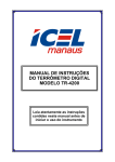
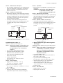
Note 2. Wiring
• All wiring shall comply with Canadian Electrical
Code Part I and Local Electrical Codes.
• In hazardous location, wiring shall be in conduit as
shown in the figure.
WARNING: A SEAL SHALL BE INSTALLED
WITHIN 50 cm OF THE ENCLOSURE. UN SCELLEMENT DOIT
ÊTRE INSTALLÉ À MOINS DE
50 cm DU BOÎTIER.
• When installed in Division 2, “FACTORY
SEALED, CONDUIT SEAL NOT REQUIRED”.
Note 3. Operation
• Keep strictly the “WARNING” on the label
attached on the transmitter.
WARNING: OPEN CIRCUIT BEFORE REMOVING COVER. OUVRIR LE
CIRCUIT AVANT D´ENLEVER LE
COUVERCLE.
• Take care not to generate mechanical spark when
access to the instrument and peripheral devices in
hazardous location.
Note 4. Maintenance and Repair
• The instrument modification or parts replacement
by other than authorized representative of
Yokogawa Electric Corporation is prohibited and
will void Canadian Standards Explosionproof
Certification.
• Encl. “Type 4X”
• Temperature Class: T4
• Ambient temperature: –40 to 60°C
Note 2. Entity Parameters (Electrical/Nonincendive field wiring parameters)
• [Supply Circuit]
Vmax = 30 V, Imax = 165 mA, Pmax = 0.9 W
Ci = 18 nF, Li = 730 µH
• [Associated apparatus]
Voc ≤ 30 V, Isc ≤ 165 mA, Pmax ≤ 0.9 W
• [Sensor Circuit]
Voc = 9 V, Isc = 40 mA, Po = 90 mW,
Ca = 1 µF, La = 10 mH
Note 3. Installation
• All wiring shall comply with Canadian Electrical
Code Part I and Local Electrical Codes.
• For the sensor circuitry, the above parameters for
sensor circuit must be taken into account.
• Dust-tight conduit seal must be used when installed in
class II and III environments.
• In any used safety barrier, output current must be
limited by a resistor 'R' such that Isc=Voc/R.
• The safety barrier must be CSA certified, and the
input voltage of the barrier must be less than
250Vrms/Vdc.
• For non-incendive type, general purpose equipment
must be CSA certified and the equipment which have
non-incendive field wiring parameters.
• The instrument modification or parts replacement by
other than authorized representative of Yokogawa
Electric Corporation is prohibited and will void
Canadian Standards Intrinsically safe and
nonincendive Certification.
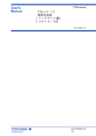
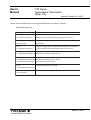
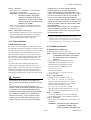
[Intrinsically Safe]
Hazardous
Nonhazardous
Location
Location
YTA Series
Temperature
Transmitter
Safety Barrier
+
1
Supply
2
–
3
4 Sensor
5
General
Purpose
Equipment
+ +
+
–
–
–
[Non-incendive]
Hazardous
Location
Nonhazardous
Location
YTA Series
Temperature
Transmitter
1
+
2
Supply
3
–
4 Sensor
5
General
Purpose
Equipment
+
–
Not Use
Safety Barrier
F0204.EPS
2-4
IM 01C50B01-01E
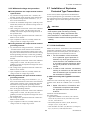
2. NOTES ON HANDLING
HAZARDOUS LOCATIONS DIVISION 1
50 cm Max.
50 cm Max.
YTA Series
NON-HAZARDOUS
LOCATIONS
Non-hazardous
Location
Equipment
Sensor
Conduit
Sealing Fitting
Sealing Fitting
42 V DC Max.
4 to 20 mA DC
Signal
Certified/Listed Temperature Sensor
Explosionproof Class I, Groups C and D
Dustignitionproof Class II, Groups E, F and G, Class III
Wiring method shall be suitable for the specified hazardous locations.
HAZARDOUS LOCATIONS DIVISION 2
NON-HAZARDOUS
LOCATIONS
YTA Series
Non-hazardous
Location
Equipment
Sensor
Conduit
Sealing Fitting
42 V DC Max.
4 to 20 mA DC
Signal
Certified/Listed Temperature Sensor
Explosionproof Class I, Groups C and D
Dustignitionproof Class II, Groups E, F and G, Class III
Wiring method shall be suitable for the specified hazardous locations.
F0203.EPS
2.7.2 ATEX Certification
Model YTA110/KU2, YTA310/KU2 and YTA320/
KU2 temperature transmitters can be selected the type
of protection (ATEX Intrinsically Safe or ATEX
Flameproof or ATEX Type of Protection “n”) for use
in hazardous locations.
Note 1. For the installation of this transmitter,
once a particular type of protection is
selected, any other type of protection
cannot be used. The installation must be
in accordance with the description about
the type of protection in this instruction
manual.
Note 2. In order to avoid confusion, unnecessary
marking is crossed out on the label other
than the selected type of protection when
the transmitter is installed.
(1) Technical Data
a) ATEX Intrinsically Safe Type
Caution for ATEX Intrinsically safe type
Note 1. Model YTA110/KU2, YTA310/KU2 and
YTA320/KU2 temperature transmitters for
potentially explosive atmospheres:
• No. KEMA 02ATEX1026X
• Applicable Standard: EN 60079-0:2009,
EN 60079-11:2007, EN 60079-26:2007,
EN 60529:1991
• Type of Protection and Marking code: II 1G Ex ia
IIC T4...T5
• Temperature Class: T5, T4
• Ambient Temperature: –40 to 70°C for T4,
–40 to 50°C for T5
• Enclosure: IP67
Note 2. Electrical Data
• In type of explosion protection intrinsic safety II 1G
Ex ia IIC only for connection to a certified intrinsically safe circuit with following maximum values:
• [Supply circuit]
Ui = 30 V
Ii = 165 mA
Pi = 900 mW
Effective internal capacitance, Ci = 20 nF
Effective internal inductance, Li = 730 µH
• [Sensor circuit]
Uo = 9 V
Io = 40 mA
Po = 90 mW
Max. allowed external capacitance, Co = 0.7µF
Max. allowed external inductance, Lo = 10 mH
Note 3. Installation
• All wiring shall comply with local installation
requirements. (Refer to the installation diagram)
Note 4. Operation
• Keep strictly the “WARNING” on the label on the
transmitter.
WARNING: POTENTIAL ELECTROSTATIC
CHARGING HAZARD. SEE
USER’S MANUAL BEFORE USE.
2-5
IM 01C50B01-01E
2. NOTES ON HANDLING
Note 5. Maintenance and Repair
• The instrument modification or parts replacement by
other than authorized representative of Yokogawa
Electric Corporation is prohibited and will void
ATEX Intrinsically safe Certification.
Note 6. Special condition for safe use
• Because the enclosure of the Temperature Transmitter is made of aluminium, if it is mounted in an area
where the use of category 1G apparatus is required,
it must be installed such, that, even in the event of
rare incidents, ignition source due to impact and
friction sparks are excluded.
• Avoid any actions that cause the generation of
electrostatic charge on the non-metallic parts, such
as rubbing with a dry cloth on coating face of
product.
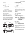
[Installation Diagram]
Hazardous
Location
Transmitter
1
+
2
Supply
3
–
4 Sensor
5
Nonhazardous
Location
Safety Barrier *1
Note 3. Installation
• All wiring shall comply with local installation
requirement.
• The cable entry devices shall be of a certified
flameproof type, suitable for the conditions of use.
Note 4. Operation
• Keep strictly the “WARNING” on the label on the
transmitter.
WARNING: AFTER DE-ENERGIZING, DELAY
5 MINUTES BEFORE OPENING.
WHEN THE AMBIENT TEMP. ⭌
70⬚C, USE THE HEATRESISTING
CABLES OF HIGHER THAN 90⬚C.
• Take care not to generate mechanical spark when
access to the instrument and peripheral devices in
hazardous location.
Note 5. Maintenance and Repair
• The instrument modification or parts replacement by
other than authorized representative of Yokogawa
Electric Corporation is prohibited and will void
ATEX Flameproof Certification.
+
c) ATEX Type of Protection “n”
–
WARNING
F0208.EPS
When using a power supply not having a nonincendive circuit, please pay attention not to
ignite in the surrounding flammable atmosphere.
In such a case, we recommend using wiring
metal conduit in order to prevent the ignition.
*1: In any safety barriers used the output current must be limited by
a resistor “R” such that Imaxout-Uz/R.
b) ATEX Flameproof Type and Dust Ignition
Proof Type
Caution for ATEX Flameproof Type and Dust Ignition
Proof Type
Note 1. Model YTA110/KU2, YTA310/KU2 and
YTA320/KU2 temperature transmitters
are applicable for use in hazardous
locations:
• No. KEMA 07ATEX0130
• Applicable Standard: EN 60079-0:2006,
IEC 60079-1:2007, EN 61241-0:2006,
EN 61241-1:2004
• Type of Protection and Marking Code: II 2G Ex d
IIC T6/T5, II 2D Ex tD A21 IP67 T70°C, T90°C
• Ambient Temperature for Gas Atmospheres:
–40 to 75°C (T6), –40 to 80°C (T5)
• Ambient Temperature for Dust Atmospheres:
–40 to 65°C (T70°C), –40 to 80°C (T90°C)
• Enclosure: IP67
Note 2. Electrical Data
• Supply voltage: 42 V dc max.
• Output signal: 4 to 20 mA
Caution for ATEX Type of Protection “n”
Note 1. Model YTA110/KU2, YTA310/KU2 and
YTA320/KU2 temperature transmitters for
potentially explosive atmospheres:
• Applicable standard: EN60079-15:2005,
EN60079-0:2009
• Type of Protection and Marking Code: II 3G Ex nL
IIC T4...T5 Gc
• Temperature Class: T5, T4
• Ambient Temperature: –30 to 50°C for T5, –30 to
70°C for T4
• Enclosure: IP67
Note 2. Electrical Data
[Supply circuit]
Ui = 30 V
Effective internal capacitance, Ci = 20 nF
Effective internal inductance, Li = 730 µH
[Sensor circuit]
Uo = 9 V Io = 40 mA Po = 90 mW
Max. allowed external capacitance, Co = 0.7µF
Max. allowed external inductance, Lo = 10 mH
2-6
IM 01C50B01-01E
2. NOTES ON HANDLING
Note 3. Installation
• All wiring shall comply with local installation
requirements. (refer to the installation diagram)
Note 4. Operation
• Keep strictly the “WARNING” on the label on the
transmitter.
WARNING: POTENTIAL ELECTROSTATIC
CHARGING HAZARD. SEE
USER’S MANUAL BEFORE USE.
Note 5. Maintenance and Repair
• The instrument modification or parts replacement by
other than authorized representative of Yokogawa
Electric Corporation is prohibited and will void
Type of Protection “n” Certification.
(3) Installation
WARNING
All wiring shall comply with local installation
requirement and local electrical code.
(4) Operation
WARNING
• OPEN CIRCUIT BEFORE REMOVING
COVER. INSTALL IN ACCORDANCE WITH
THIS USER’S MANUAL
• Take care not to generate mechanical sparking
when access to the instrument and peripheral
devices in hazardous locations.
[Installation Diagram]
Hazardous
Location
(Zone 2 only)
Temperature
Transmitter
+
Suppry
–
Nonhazardous
Location
Power Supply
(5) Maintenance and Repair
+
WARNING
–
The instrument modification or parts replacement
by other than authorized Representative of
Yokogawa Electric Corporation is prohibited and
will void the certification.
F0212.EPS
Ratings of the Power Supply are as follows:
Maximum Voltage: 30 V
Note 6. Special condition for safe use
• Avoid any actions that cause the generation of
electrostatic charge on the non-metallic parts, such
as rubbing with a dry cloth on coating face of
product.
(2) Electrical Connection
The type of electrical connection is stamped near
the electrical connection port according to the
following marking.
Location of the marking
F0200.EPS
2-7
IM 01C50B01-01E
2. NOTES ON HANDLING
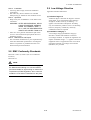
(6) Name Plate
2.7.3 FM Certification
Name plate for KU2
F0298.EPS
MODEL: Specified model code.
SUFFIX: Specified suffix code.
STYLE: Style code.
SUPPLY: Supply voltage.
NO.: Serial number and year of production*1.
OUTPUT: Output signal.
FACTORY CAL: Specified calibration range.
TOKYO 180-8750 JAPAN:
The manufacturer name and the
address*2.
*1: The third figure from the left shows the production
year. The relationship between the production year
and the third figure is shown below.
The third figure F
G
H
J
K
L
M
The year of
2006 2007 2008 2009 2010 2011 2012
Production
T0202.EPS
For example, the production year of the product
engraved in “NO.” column on the name plate as
follows is 2006.
C2F616294
The year 2006
*2: “180-8750” is a postal code which represents the
following address.
2-9-32 Nakacho, Musashino-shi, Tokyo Japan
a) FM Intrinsically Safe Type
Caution for FM Intrinsically safe type.
Note 1. Model YTA /FU1 temperature transmitter
is applicable for use in hazardous
locations
• Applicable Standard: FM 3600, FM 3610, FM 3611,
FM 3810, NEMA-250
• Intrinsically Safe for Class I, Division 1, Groups A,
B, C & D.
Class II, Division 1, Groups E, F & G and Class III,
Division 1 Hazardous Locations.
• Outdoor hazardous locations, NEMA 4X.
• Temperature Class: T4
• Ambient temperature: –40 to 60°C
Note 2. Entity Parameters of the temperature
transmitter:
• Supply Circuit (+ and –) • Sensor Circuit ( 1 to 5 )
Vmax : 30 V
Voc/Vt : 9 V
Imax : 165 mA
Isc/It : 40 mA
Pmax : 0.9 W
Po : 0.09 W
Ci : 18 nF
Ca : 1 µF
Li : 730 µH
La : 10 mH
• For the sensor input circuitry, these entity parameters
must be taken into account when installed.
• Installation Requirements between temperature
transmitter and safety barrier:
Voc ≤ Vmax, Isc ≤ Imax, Ca ≥ Ci + Ccable, La ≥
Li + Lcable
Voc, Isc, Ca and La are parameters of the safety
barrier.
Note 3. Installation
• The safety barrier must be FM approved.
• Input voltage of the safety barrier must be less than
250 Vrms/Vdc.
• Installation should be in accordance with ANSI/ISA
RP12.6 “Installation of Intrinsically Safe Systems
for Hazardous (Classified) Locations” and the
National Electric Code (ANSI/NFPA 70).
• Intrinsically safe sensor must be FMRC Approved or
be simple apparatus (a device which will neither
generate nor store more than 1.2 V, 0.1 A, 25 mW
or 20 µJ, ex. switches, thermocouples, LED’s or
RTD’s).
• Dust-tight conduit seal must be used when installed
in a Class II and III environments.
Note 4. Maintenance and Repair
• The instrument modification or parts replacement by
other than authorized representative of Yokogawa
Electric Corporation is prohibited and will void
Factory Mutual Intrinsically safe and Nonincendive
Approval.
2-8
IM 01C50B01-01E
2. NOTES ON HANDLING
[Intrinsically Safe]
Hazardous
Location
Class I, II, III, Division 1,
Groups A, B, C, D, E, F and G
Nonhazardous
Location
General
Purpose
Equipment
+
Intrinsically
Safe Sensor
or Simple
Apparatus
Temperature
Transmitter
1
+
2
Supply
3
–
4 Sensor
C
5
–
Safety Barrier
+ +
–
–
F0210.EPS
b) FM Non-incendive Type
Caution for FM Non-incendive type.
Note 1. Model YTA /FU1 temperature transmitter
is applicable for use in hazardous
locations
• Applicable Standard: FM 3600, FM 3610, FM 3611,
FM 3810, NEMA-250
• Non-incendive for Class I, Division 2, Groups A, B,
C & D.
Class II, Division 2, Groups F & G and Class III,
Division 1 Hazardous Locations.
• Outdoor hazardous locations, NEMA 4X.
• Temperature Class: T4
• Ambient temperature: –40 to 60°C
Note 2. Non-incendive field wiring Parameters of
the temperature transmitter:
• Supply Circuit (+ and -) • Sensor Circuit ( 1 to 5 )
Vmax : 30 V
Voc/Vt : 9 V
Imax : 165 mA
Isc/It : 40 mA
Pmax : 0.9 W
Po : 0.09 W
Ci : 18 nF
Ca : 1 µF
Li : 730 µH
La : 10 mH
• For the sensor input circuitry, these non-incendive
parameters must be taken into account when
installed.
• Installation Requirements between temperature
transmitter and general purpose equipment:
Voc ≤ Vmax, Isc ≤ Imax, Ca ≥ Ci + Ccable, La ≥
Li + Lcable
Voc , Isc, Ca and La are non-incendive field wiring
parameters of general purpose equipment.
Note 3. Installation
• The general purpose equipment must be FM approved which have non-incendive field wiring
parameters.
• Installation should be in accordance with ANSI/ISA
RP12.6 “Installation of Intrinsically Safe Systems
for Hazardous (Classified) Locations” and the
National Electric Code (ANSI/NFPA 70).
• non-incendive sensor must be FMRC Approved or
be simple apparatus (a device which will neither
generate nor store more than 1.2 V, 0.1 A, 25 mW
or 20 µJ, ex. switches, thermocouples, LED’s or
RTD’s).
• Dust-tight conduit seal must be used when installed
in a Class II and III environments.
Note 4. Maintenance and Repair
• The instrument modification or parts replacement by
other than authorized representative of Yokogawa
Electric Corporation is prohibited and will void
Factory Mutual Intrinsically safe and Nonincendive
Approval.
[Nonincendive]
Hazardous
Location
Nonhazardous
Location
Class I, II, Division 2,
Groups A, B, C, D, E, F and G
Class III, Division 1.
Non-incendive
Sensor
or Simple
Apparatus
Temperature
Transmitter
1
+
2
Supply
3
–
4 Sensor
C
5
General
Purpose
Equipment
+
–
F0211.EPS
c) FM Explosionproof Type
Caution for FM Explosionproof type
Note 1. Model YTA /FU1 and YTA /FF1 temperature transmitters are applicable for use in
hazardous locations:
• Applicable Standard: FM 3600, FM 3615, FM 3810,
NEMA 250
• Explosionproof for Class I, Division 1, Groups A, B,
C, and D.
• Dust-ignitionproof for Class II/III, Division 1,
Groups E, F and G.
• Enclosure rating: NEMA 4X.
• Temperature Class: T6
• Ambient Temperature: –40 to 60°C
• Supply Voltage: 42 V dc max.
• Output signal: 4 to 20 mA
Note 2. Wiring
• All wiring shall comply with National Electrical
Code ANSI/NEPA70 and Local Electrical Codes.
• “FACTORY SEALED, CONDUIT SEAL NOT
REQUIRED”.
2-9
IM 01C50B01-01E
2. NOTES ON HANDLING
Note 3. Operation
• Keep strictly the “WARNING” on the nameplate
attached on the transmitter.
WARNING: OPEN CIRCUIT BEFORE REMOVING COVER. “FACTORY
SEALED, CONDUIT SEAL NOT
REQUIRED”. INSTALL IN ACCORDANCE WITH THE INSTRUCTION
MANUAL IM 1C50B1.
• Take care not to generate mechanical spark when
access to the instrument and peripheral devices in
hazardous location.
Note 4. Maintenance and Repair
• The instrument modification or parts replacement by
other than authorized representative of Yokogawa
Electric Corporation is prohibited and will void
Factory Mutual Explosionproof Approval.
2.7.4 TIIS Certification
a) TIIS Flameproof Type
The model YTA /JF3 temperature transmitter, which
has obtained certification according to technical criteria
for explosion-protected construction of electric machinery and equipment (Standards Notification No.556
from the Japanese Ministry of Labor) conforming to
IEC standards, is designed for hazardous areas where
explosive gases and/or inflammable vapors may be
present. (This allows installation in Division 1 and 2
areas)
To preserve the safety of flameproof equipment
requires great care during mounting, wiring, and
piping. Safety requirements also place restrictions on
maintenance and repair activities. Users absolutely
must read “Installation and Operating Precautions for
TIIS Flameproof Equipment” at the end of this manual.
WARNING
The terminal cover should not be opened at
least for three minutes after the power is turned
off.
The terminal section of the flameproof YTA
series is made of resin-filled, explosion-protected
construction. The technical standards for this
flameproof construction require that the possibility of explosion resulting from a prospective
short-circuit current*1 of up to 4000 A be prevented even for cases when external power
supply circuits are short-circuited accidentally.
Install a fuse or a circuit breaker having a
breaking capacity of at least 4000 A in the
higher-order power line connected to the YTA
series. The breaking capacity refers to the upper
limit of current that can be cut off. Normally, a
fuse or a circuit breaker having a breaking
capacity of greater than 5000 A is used in power
supply circuits. Confirm that this is true with your
factory. No extra measures need be taken after
the confirmation.
Note that the rated current of the YTA series in
terms of explosion protection is 4 to 20 mA;
keep the input current of the YTA series within
the appropriate range.
*1: Refers to a current that flows when a fuse in a circuit is
substituted with a connecting metal piece having virtually no
impedance and the circuit is then shorted. For AC circuits, this
current is represented by a root-mean-square value (JIS C6575).
2.7.5 IECEx Certification
a) IECEx Intrinsic safety “ia”
Caution for IECEx Intrinsic safety “ia”.
Note 1. Model YTA110/SU2, YTA310/SU2, and
YTA320/SU2 temperature transmitters
are applicable for use in hazardous
locations:
• No. Certificate: IECEx KEM 09.0032X
• Applicable standard: IEC60079-11:2011,
IEC60079-0:2011, IEC60079-26:2006
• Type of Protection and Marking Code:
Ex ia IIC T4...T5 Ga
• Ambient Temperature:
-40 to 70°C for T4, -40 to 50°C for T5
• Enclosure: IP67
Note 2. Electrical Data
• [Supply circuit (Terminals: + and –)]
Ui = 30 V Ii = 165 mA Pi = 900 mW
Effective internal capacitance, Ci = 20 nF
Effective internal inductance, Li = 730 µH
• [Sensor circuit (Terminals: 1 to 5)]
Uo = 9 V Io = 40 mA Po = 90 mW
Max. allowed external capacitance, Co = 0.7 µF
Max. allowed external inductance, Lo = 10 mH
Note 3. Installation
• All wiring shall comply with local installation
requirements. (Refer to the installation diagram)
Note 4. Operation
• Keep strictly the “WARNING” on the label on the
transmitter.
WARNING: POTENTIAL ELECTROSTATIC
CHARGING HAZARD. SEE
USER’S MANUAL BEFORE USE.
2-10
IM 01C50B01-01E
2. NOTES ON HANDLING
Note 5. Maintenance and Repair
• The instrument modification or parts replacement by
other than authorized representative of Yokogawa
Electric Corporation is prohibited and will void
IECEx Certification.
Note 6. Conditions of Certification
• Because the enclosure of the Temperature Transmitter is made of aluminium, if it is mounted in zone 0,
it must be installed such, that, even in the event of
rare incidents, ignition sources due to impact and
friction sparks are excluded.
• Avoid any actions that cause the generation of
electrostatic charge on the non-metallic parts, such
as rubbing with a dry cloth on coating face of
product.
[Installation Diagram]
Hazardous
Location
Transmitter
1
+
2
Supply
3
–
4 Sensor
5
Note 4. Operation
• Keep strictly the “WARNING” on the label on the
transmitter.
WARNING: POTENTIAL ELECTROSTATIC
CHARGING HAZARD. SEE
USER’S MANUAL BEFORE USE.
Note 5. Maintenance and Repair
• The instrument modification or parts replacement by
other than authorized representative of Yokogawa
Electric Corporation is prohibited and will void
IECEx Certification.
Note 6. Special condition for safe use
• Avoid any actions that cause the generation of
electrostatic charge on the non-metallic parts, such
as rubbing with a dry cloth on coating face of
product.
Nonhazardous
Location
[Installation Diagram]
Hazardous
Location
(Zone 2 only)
Safety Barrier *1
+
Temperature
Transmitter
–
+
Suppry
–
Nonhazardous
Location
Power Supply
+
–
F0214.EPS
F0215.EPS
*1: In any safety barriers used the output current must be limited by
a resistor “R” such that Imaxout-Uz/R.
b) IECEx Intrinsic safety “ic”
Caution for IECEx Intrinsic safety “ic”.
Note 1. Model YTA110/SU2, YTA310/SU2, and
YTA320/SU2 temperature transmitters
are applicable for use in hazardous
locations:
• No. Certificate: IECEx KEM 09.0032X
• Applicable standard: IEC60079-11:2011,
IEC60079-0:2011, IEC60079-26:2006
• Type of Protection and Marking Code:
Ex ic IIC T4...T5 Gc
• Ambient Temperature:
-40 to 70°C for T4, -40 to 50°C for T5
• Enclosure: IP67
Note 2. Electrical Data
• [Supply circuit (Terminals: + and –)]
Ui = 30 V, Ci = 20 nF, Li = 730 µH
• [Sensor circuit (Terminals: 1 to 5)]
Uo = 9 V, Io = 40 mA, Po = 90 mW, Co = 0.7 µF,
Lo = 10 mH
Note 3. Installation
• All wiring shall comply with local installation
requirements. (Refer to the installation diagram)
Ratings of the Power Supply are as follows:
Maximum Voltage: 30 V
c) IECEx Flameproof Type and Dust Ignition
Proof Type
Caution for IECEx flameproof type and Dust Ignition
Proof Type
Note 1. Model YTA110/SF2, YTA310/SF2, and
YTA320/SF2, YTA110/SU2, YTA310/
SU2, and YTA320/SU2 temperature
transmitters are applicable for use in
hazardous locations:
• No. IECEx KEM 07.0044
• Applicable Standard: IEC 60079-0, IEC 60079-1,
IEC 61241-0, IEC 61241-1
• Type of Protection and Marking Code:
Ex d IIC T6/T5, Ex tD A21 IP67 T70°C, T90°C
• Ambient Temperature for Gas Atmospheres:
–40 to 75°C (T6), –40 to 80°C (T5)
• Ambient Temperature for Dust Atmospheres:
–40 to 65°C (T70°C), –40 to 80°C (T90°C)
• Enclosure: IP67
Note 2. Electrical Data
• Supply voltage: 42 V dc max.
• Output signal: 4 to 20 mA
2-11
IM 01C50B01-01E
2. NOTES ON HANDLING
Note 3. Installation
• All wiring shall comply with local installation
requirement.
• The cable entry devices shall be of a certified
flameproof type, suitable for the conditions of use.
Note 4. Operation
• Keep strictly the “WARNING” on the label on the
transmitter.
WARNING: AFTER DE-ENERGIZING, DELAY
5 MINUTES BEFORE OPENING.
WHEN THE AMBIENT TEMP. ⭌
70°C, USE THE HEATRESISTING
CABLES OF HIGHER THAN 90°C.
• Take care not to generate mechanical spark when
access to the instrument and peripheral devices in
hazardous location.
Note 5. Maintenance and Repair
• The instrument modification or parts replacement by
other than authorized representative of Yokogawa
Electric Corporation is prohibited and will void
IECEx Flameproof Certification.
2.9 Low Voltage Directive
Applicable standard: EN61010-1
(1) Pollution Degree 2
“Pollution degree” describes the degree to which a
soild, liquid, or gas which deteriorates dielectric
strength or surface resistivity is adhering. “ 2 ”
applies to normal indoor atmosphere. Normally,
only non-conductive pollution occurs. Occasionally,
however, temporary conductivity caused by
condenstaion must be expected.
(2) Installation Category I
“Overvoltage category(Installation category)”
describes a number which defines a transient
overvoltage condition. It implies the regulattion for
impulse withstand voltage. “ I ” applies to electrical
equipment which is supplied from the circuit when
appropriate transient overvoltage control means
(interfaces) are provided.
2.8 EMC Conformity Standards
EN61326-1 Class A, Table 2 (For use in industrial
locations)
EN61326-2-3
NOTE
YOKOGAWA recommends customer to apply
the Metal Conduit Wiring or to use the twisted
pair Shield Cable for signal wiring to conform the
requirement of EMC Regulation, when customer
installs the YTA Series Transmitters to the plant.
2-12
IM 01C50B01-01E
7. GENERAL SPECIFICATIONS
Ambient humidity:
5 to 100%RH at 40°C (104°F)
Effect of supply voltage fluctuation:
±0.005%/V
Insulation:
Input/output insulated at 500 V DC
Mounting:
Mounted on 2B pipes and wall
Degrees of Protection:
IP66/IP67, NEMA 4X
Electrical connection:
Refer to “Model and Specification Codes”.
Case and cover:
Aluminum alloy casting
Painting:
Polyurethane resin baked finish
Deep sea moss green (equivalent of Munsell
0.6GY3.1/2.0)
Integral indicator (option):
LCD digital indicator (5-digit display)
Output bar graph; 0 to 100% display
Damping constant:
0 to 99 seconds (integer range that can be set)
Sensor burnout (Output Signal Code D&E) :
High (110%, 21.6 mA DC) or Low (–2.5%, 3.6
mA DC)
Weight:
1.2 kg; without built-in indicator (without mounting bracket)
1.4 kg; with Integral indicator (without mounting
bracket)
EMC compliant standard:
,
EN61326, AS/NZS CISPR11
Material Cross Reference Table
SUS304
AISI 304
SUS316
AISI 316
T0707.EPS
7-2
IM 01C50B01-01E
7. GENERAL SPECIFICATIONS
Table 7.1
Sensor Type
Input Type, Measurement Range and Accuracy
Measurement Range
Reference
Standard
B
C
Minimum Span
(Recommended)
F
100 to 1820
212 to 3308
Accuracy
Input range
C
100 to
300 to
-200 to 1000
-200 to 1200
J
572
±
3.0
±
5.4
572 to
752
±
1.0
±
1.8
752 to 3308
±
0.75
± 1.35
-58
±
0.35
± 0.63
-58 to 1832
±
0.16
± 0.29
-58
±
0.40
± 0.72
-58 to 2192
±
0.20
± 0.36
-58
±
0.50
-200 to 1372
K
± 0.90
-58 to 2502
±
0.25
± 0.45
-58
±
0.80
N
IEC584
-200 to 1300
± 1.44
-50 to 1300
-58 to 2372
±
0.35
± 0.63
-50 to
0
-58 to
32
±
1.0
-50 to 1768
0 to
100
32 to
212
±
0.80
± 1.44
R
100 to
600
212 to 1112
±
0.60
± 1.08
600 to 1768
1112 to 3214
±
0.40
± 0.72
-200 to
-200 to
-328 to 2502
-200 to
-328 to 2372
-58 to 3214
(45 F)
T
-200 to
W3
400
0 to 2300
-58 to 3214
-328 to
752
32 to 4172
ASTM
E988
0 to 2300
L
-200 to
900
32 to 4172
-328 to 1652
DIN43710
RTD
-50
-328 to
-328 to
-328 to
-328 to
±
±
1.8
-50 to
0
-58 to
32
±
1.0
0 to
100
32 to
212
±
0.80
± 1.44
100 to
600
212 to 1112
±
0.60
± 1.08
600 to 1768
1112 to 3214
±
0.40
± 0.72
1.8
-200 to
-50
-328 to
-58
±
0.25
± 0.45
-50 to
400
-58 to
752
±
0.14
± 0.25
0 to
400
32 to
752
±
0.80
± 1.44
400 to 1400
752 to 2552
±
0.50
± 0.90
1400 to 2000
2552 to 3632
±
0.60
± 1.08
2000 to 2300
3632 to 4172
±
0.90
± 1.62
752
±
0.70
± 1.26
400 to 1400
752 to 2552
±
0.50
± 0.90
1400 to 2000
2552 to 3632
±
0.70
± 1.26
2000 to 2300
3632 to 4172
±
0.90
± 1.62
-200 to
-50
-328 to
-58
±
0.30
± 0.54
-50 to
900
-58 to 1652
±
0.20
± 0.36
-200 to
-50
-58
±
0.50
± 0.90
-50 to
600
-58 to 1112
±
0.25
± 0.45
0 to
W5
-50
-50 to 1372
25 C
S
-50
-50 to 1200
T/C
-50 to 1768
-50
-50 to 1000
-328 to 2192
D/A
Accuracy
F
400
-200 to
-328 to 1832
C
300
400 to 1820
E
A/D Accuracy
F
212 to
400
32 to
-328 to
U
-200 to
600
-328 to 1112
Pt100
Pt200
-200 to
850
-328 to 1562
-200 to
850
-328 to 1562
±
0.14
± 0.25
-200 to
850
-328 to 1562
-200 to
850
-328 to 1562
±
0.30
± 0.54
Pt500
-200 to
850
-328 to 1562
10 C
-200 to
850
-328 to 1562
±
0.20
± 0.36
JPt100 JIS C1604
-200 to
500
-328 to
(18 F)
-200 to
500
-328 to
932
±
0.16
± 0.29
-70 to
-40
-94 to
-40
±
1.35
-40 to
150
-40 to
302
±
1.0
-70 to
320
-94 to
608
±
0.11
Cu
IEC751
SAMA
RC21-4
Ni120
932
-70 to
150
-94 to
302
-70 to
320
-94 to
608
± 0.02%
of span
± 2.43
±
1.8
± 0.19
mV
-10 to 100 [mV]
3 [mV]
± 12 [µ V]
ohm
0 to 2000 [Ω]
20 [Ω]
± 0.35 [Ω]
T0701.EPS
Table 7.2
YTA110 Effect of Ambient Temperature
Sensor Type
Temperature Coefficient
Thermocouples E, J, K, N, T, L, U
0.08C + 0.02% of abs.reading
Thermocouples R, S, W3, W5
0.25C + 0.02% of abs.reading
T/C B
RTD
mV
ohm
100C " Reading < 300C
300C " Reading
1C + 0.02% of abs.reading
0.5C + 0.02% of abs.reading
0.08C + 0.02% of abs.reading
0.002 mV + 0.02% of abs.reading
0.1 + 0.02% of abs.reading
T07021.EPS
Note1: Ambient Temperature Effect per 10°C change is !0.1% or
!(temperature coefficient/span), whichever is greater.
Note2: The “abs.reading” on Table7.2 means the absolute value of
the reading in °C.
Example of abs reading;
When the temperature value is 250 Kelvin, abs reading is
23.15, absolute (250273.15).
Example of Ambient Temperature Effect;
Conditions;
1) Input Sensor:Pt100 2) Calibration Range:100 to 100°C
3) Reading value: 50°C
Ambient Temperature Effect per 10°C;
Temperature Coefficient/Span
=(0.08°C#0.02/100$|50°C|)/{100°C(100°C)}= 0.00045
→ 0.045%
Therefore, Ambient Temperature Effect is !0.1%/10°C
7-3
IM 01C50B01-01E
7. GENERAL SPECIFICATIONS
Table 7.3
YTA310, YTA320 Effect of Ambient Temperature
Input Range
Sensor Type
B
E
J
K
N
R
T/C
S
T
W3
W5
L
U
Pt100
Pt200
Pt500
RTD
JPt100
Cu
Ni120
mV
ohm
100
300
1000
-200
-200
0
-200
0
-200
0
-50
200
-50
200
-200
0
0
1400
0
1400
-200
0
-200
0
-200
-200
-200
-200
-70
-70
C
to
to
to
to
to
to
to
to
to
to
to
to
to
to
to
to
to
to
to
to
to
to
to
to
to
to
to
to
to
to
300
1000
1820
1000
0
1200
0
1372
0
1300
200
1768
200
1768
0
400
1400
2300
1400
2300
0
900
0
600
850
850
850
500
150
320
212
572
1832
-328
-328
32
-328
32
-328
32
-58
392
-58
392
-328
32
32
2552
32
2552
-328
32
-328
32
-328
-328
-328
-328
-94
-94
F
to
to
to
to
to
to
to
to
to
to
to
to
to
to
to
to
to
to
to
to
to
to
to
to
to
to
to
to
to
to
A/D Coefficient
572
1832
3308
1832
32
2192
32
2502
32
2372
392
3214
392
3214
32
752
2552
4172
2552
4172
32
1652
32
1112
1562
1562
1562
932
302
608
D/A Coeffieicient
± (0.530 C0.080 % of reading)
± (0.350 C0.021 % of reading )
± (0.140 C)
± (0.035 C#0.042 % of abs.reading)
± (0.039 C#0.020 % of abs.reading)
± (0.039 C#0.0029 % of reading)
± (0.046 C#0.020 % of abs.reading)
± (0.046 C#0.0054 % of reading)
± (0.054 C#0.010 % of abs.reading)
± (0.054 C#0.0036 % of reading)
± (0.210 C0.032 % of abs.reading)
± (0.150 C)
± (0.210 C0.032 % of abs.reading)
± (0.150 C)
± (0.046 C0.036 % of abs.reading) ± {0.0088% of span#0.007% of (readingLRV)}
± (0.046 C)
± (0.100 C#0.0040 % of reading)
± ( -0.130C#0.020 % of reading)
± (0.100 C#0.0040 % of reading)
± ( -0.120C#0.020 % of reading)
± (0.039 C#0.020 % of abs.reading)
± (0.039 C#0.0029 % of reading)
± (0.046 C#0.036 % of abs.reading)
± (0.046 C)
± ( 0.047 C#0.009 % of reading)
± ( 0.065 C#0.012 % of reading)
± ( 0.047 C#0.009 % of reading)
± ( 0.047 C#0.009 % of reading)
± ( 0.320 C#0.120 % of reading)
± ( 0.016 C#0.007 % of reading)
± (0.001mV#0.0043 % of abs.reading)
± (0.040 #0.0088 % of reading)
T07022.EPS
Note: Temperature Effect = A/D coeffieicnt + D/A coefficient (The data in the table is the coeffcient per 10C change.)
Example 1; Pt100, 0 to 200C calibration range, 50C reading
(0.047C # 50C $ 0.009%) # [200C $ 0.0088% # (50 0) $ 0.007%]
= (0.047C # 0.0045C) # (0.0176C # 0.0035C )
= ± 0.0726C [ per 10C change ]
Example 2; T T/C, 100 to 100C calibration range, 250C reading
(0.046C # | 250C | $ 0.036%) # {200C $ 0.0088% # [250 (100)] $ 0.007%}
= (0.046C # 0.018C) # (0.0176C # 0.0035C )
= ± 0.0851C [ per 10C change ]
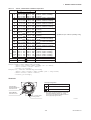
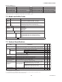
Terminals
Terminal Configuration
Power Supply and output terminal
Communication
Terminals (BT200 etc.)
Connection hook
External Indicator (ammeter) terminal *2
Ground terminal
CHECK METER
Connection hook *2
M10$1.5 12-deep female
for mounting bracket
*2: When using an external indicator or check meter,
the internal resistance must be 10Ω or less.
The hook is not available for Fieldbus communication type(output signal code F).
F0702.EPS
7-4
IM 01C50B01-01E
7. GENERAL SPECIFICATIONS
Factory setting ()
Tag No.
Left blank if not specified in order
Unit of calibration range
“°C” if not specified in order
Input sensor type
“Pt100, 3-wire” if not specified in order
Damping constant
2 seconds
Lower calibration range
“0” if not specified in order
Sensor burnout
High side (110%, 21.6 mA DC) *1
Upper calibration range
“100” if not specified in order
Output when transmitter fails
High side (110%, 21.6 mA DC) *2
T0705.EPS
*1: When option code C1 is specified, Low takes effect (–2.5%, 3.6mADC).
*2: When option code C1 is specified, Low takes effect (–5%, 3.2mADC or less).
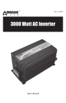
7.2 Model and Suffix Codes
Model
Basic Specification Codes
Description
. . . . . . . . . . . . . . . . . . . . . . Temperature transmitter (1 input type)
. . . . . . . . . . . . . . . . . . . . . . High precision temperature transmitter (1 input type)
. . . . . . . . . . . . . . . . . . . . . . High precision temperature transmitter (2 input type)
YTA110
YTA310
YTA320
Output
signal
–D . . . . . . . . . . . . . . . . . . . . 4 to 20mA DC output, BRAIN communication type
–E . . . . . . . . . . . . . . . . . . . . 4 to 20mA DC output, HART communication type
–F . . . . . . . . . . . . . . . . . . . . FOUNDATION Fieldbus communication type (YTA320 only)
A.................
—
Electrical
connection
Built-in indicator
0...............
2...............
3...............
4...............
D............
N............
Mounting bracket
B.........
D.........
J.........
K.........
N.........
/
Additional specifications
Always A
G1/2 female
1/2 NPT female
Pg13.5 female
M20 female
Digital indicator
None
SUS304 Stainless steel 2-inch horizontal pipe mounting *1
SUS304 Stainless steel 2-inch vertical pipe mounting *1
SUS316 Stainless steel 2-inch horizontal pipe mounting *1
SUS316 Stainless steel 2-inch vertical pipe mounting *1
None
Additional specifications
T0703.EPS
*1: Use bolts for wall mounting.
Lightning protector
Descriptions
Power supply voltage: 10.5 to 32 V DC
Allowable current: Max. 6000A(140s), repeating 1000A(140s) 100 times
Coating change Epoxy resin coating
Painting
Color change
Munsell renotation code: NI1.5 Black
Amplifier cover only
Munsell renotation code: 7.5BG4/1.5, Jade green
Metallic silver
Amplifier and Terminal covers Munsell renotation code: 7.5R4/14 Red
YTA110
Item
YTA310
YTA320
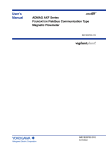
7.3 Optional Specifications
A
X1
P1
P2
P7
Code
PR
SUS316 exterior parts
Exterior parts on the amplifier housing (name plates, tag plate, screws)
will become SUS316 stainless steel *3
HC
Stainless Steel Housing*1
Wired tag plate
Calibration Unit
Housing Material: SCS14A Stainless steel
SUS304 stainless steel tag plate wired onto transmitter *4
Addition of Degree F and Degree R unit
E1
N4
D2
Output signal low-side in
Transmitter failure*2
Output signal low-side: –5 %, 3.2 mA DC or less.
Sensor burnout is also set to ‘Low’: –2.5 %, 3.6 mA DC
C1
Failure alarm down-scale: output status at CPU failure
and hardware error is –5%, 3.2 mA or less.
Sensor burnout is also set to ‘Low’: –2.5%, 3.6 mA
C2
Failure alarm up-scale: output status at CPU failure and
hardware error is 110%, 21.6 mA or more.
Sensor burnout is also set to ‘High’: 110%, 21.6 mA
C3
CA
CM1
NAMUR NE43
compliant*2
Output signal limits:
3.8 mA to 20.5 mA
Data Configuration*2
Description into “Descriptor” parameter of HART protocol. (max. 16 characters)
Sensor matching function*2
RTD Sensor matching function
*1 : Not applicable with other option codes, except for A, C1, D2 and CM1.
*2 : Not applicable for output signal code F.
*3 : This specification is not included in option code E1. Select HC for SUS316 exterior parts regardless of E1.
*4 : When HC is selected, the material is SUS316 stainless steel.
7-5
T0704.EPS
IM 01C50B01-01E
7. GENERAL SPECIFICATIONS
[For Explosion Protected Types]
For FOUNDATION Fieldbus explosion protected type, see IM 01C50T02-01E.
Code
Descriptions
Item
ATEX
ATEX Intrinsically safe, Flameproof approval and Type n combination
Electrical Connection: 1/2 NPT female and M20 female*1
KU2
Canadian Standards
Association (CSA)
CSA Intrinsically safe, non-incendive and Explosionproof approval combination*3
Electrical Connection: 1/2 NPT female*1
CU1
FM Explosionproof approval
Electrical Connection: 1/2 NPT female*2
FF1
FM Intrinsically safe, non-incendive and Explosionproof approval combination*3
Electrical Connection: 1/2NPT female*2
FU1
Factory Mutual (FM)
Japanese Industrial
Standards (TIIS)
TIIS Flameproof approval
Attached flameproof
packing adapter*4
Electrical connection: G1/2 female
Applicable cable: O.D. 8.5 to 11 mm
IECEx
IECEx Intrinsically safe, Flameproof and Dust ignition proof Approval
Enclosure: IP67 Electrical Connection: 1/2 NPT female and M20 female*5
JF3
2 pc.
G12
SU2
*1 : Applicable for Electrical Connection Code 2 and 4.
*2 : Applicable for Electrical Connection Code 2.
*3 : Not applicable for Output Signal Code F.
*4 : If cable wiring is to be used to a TIIS flameproof type transmitter, do not fail to add the YOKOGAWA-assured flameproof packing adapter.
*5 : Applicable for Electrical connection code 2 and 4.
T0706.EPS
7-6
IM 01C50B01-01E
7. GENERAL SPECIFICATIONS
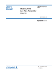
7.4 Dimensions
Unit: mm (Approx. inch)
2-inch horizontal pipe mounting
65.4(2.57)
111(4.37)
47(1.85)
66(2.60)
Electrical Connection
(Input signal)
Electrical Connection
(Output signal)
18.5
(0.73)
Terminal Cover
With Indicator
(Optional)
102
(4.02)
ø93
(3.66)
164
(6.46)
Shrouding Bolt
(For Explosionproof type)
Ground Terminal
40
(1.57) 25
(0.98)
Tag Plate
Horizontal Pipe Mounting Bracket
(Optional)
2-inch pipe, ø60.5(ø2.38)
56(2.21)
70(2.76)
90(3.54)
2-inch vertical pipe mounting
65.4(2.57)
47(1.85)
111(4.37)
Electrical Connection
(Input signal)
Electrical Connection
(Output signal)
66(2.60)
18.5
(0.73)
Terminal Cover
With Indicator
(Optional)
ø93
(3.66)
Shrouding Bolt
(For Explosionproof type)
209.5
(8.25)
191.5
(7.54)
Ground Terminal
Tag Plate
Vertical Pipe Mounting Bracket
(Optional)
46(1.81)
2-inch pipe, ø60.5(ø2.38)
64(2.52)
101(3.98)
98(3.86)
7-7
F0701.EPS
IM 01C50B01-01E


![j:j_"Xt$l"j:]:":,lg]:"r/Human Resources have been duty - e](http://vs1.manualzilla.com/store/data/005657435_1-26d97049bf04f0fd92265d73e45a9ab3-150x150.png)