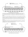
1
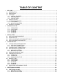
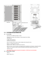
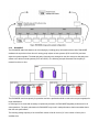
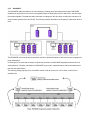
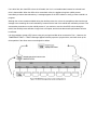
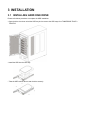
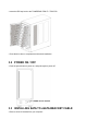
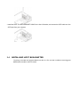
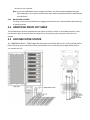
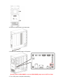
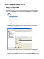
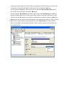
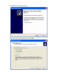
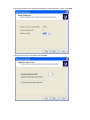
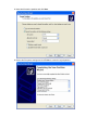
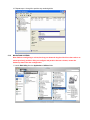
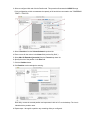
TOWERRAID TR8UT+(B)
DETAILED USER’S MANUAL v1.0
TABLE OF CONTENT
1
WELCOME ......................................................................................................................................................... 2
1.1 INTRODUCTION .......................................................................................................................................... 2
1.2 PRECAUTION .............................................................................................................................................. 3
1.3 FEATURES................................................................................................................................................... 3
1.3.1 OVERALL FEATURES .......................................................................................................................... 3
1.3.2 SATA FEATURES.................................................................................................................................. 4
1.3.3 USB FEATURES.................................................................................................................................... 4
1.4 SPECIFICATIONS........................................................................................................................................ 4
1.5 SYSTEM REQUIREMENTS ......................................................................................................................... 5
1.5.1 PC SYSTEMS ........................................................................................................................................ 5
1.5.2 MACINTOSH SYSTEMS ....................................................................................................................... 5
1.6 PRODUCT CONTENTS ............................................................................................................................... 6
2
STORAGE POLICIES......................................................................................................................................... 7
2.1.1
2.1.2
2.1.3
2.1.4
2.1.5
3
INSTALLATION................................................................................................................................................ 13
3.1
3.2
3.3
3.4
4
CLEAN MODE ....................................................................................................................................... 7
LARGE MODE ....................................................................................................................................... 7
R00 MODE............................................................................................................................................. 8
R30 MODE............................................................................................................................................. 9
R50 MODE........................................................................................................................................... 11
INSTALLING HARD DISK DRIVE .............................................................................................................. 13
POWER ON / OFF ...................................................................................................................................... 14
INSTALLING SATA TO ESATA BRACKET CABLE.................................................................................... 14
INSTALLING HOST BUS ADAPTER.......................................................................................................... 15
CONFIGURATION............................................................................................................................................ 16
4.1 CONFIGURATION PREREQUISITES ....................................................................................................... 16
4.1.1 SATA HOST CONNECTIONS ............................................................................................................. 16
4.1.2 USB HOST CONNECTIONS ............................................................................................................... 16
4.2 CHANGING HOST CONNECTIONS.......................................................................................................... 16
4.3 DISCONNECTING A USB DEVICE............................................................................................................ 16
4.3.1 WINDOWS SYSTEMS......................................................................................................................... 16
4.3.2 MACINTOSH SYSTEMS ..................................................................................................................... 17
4.4 HARD DISK DRIVE HOT SWAP ................................................................................................................ 17
4.5 LED INDICATIVE STATUS......................................................................................................................... 17
4.5.1 POWER LED........................................................................................................................................ 18
4.5.2 SYSTEM LED ...................................................................................................................................... 18
4.5.3 HRAD DISK DRIVE LED ..................................................................................................................... 18
4.6 MODE SETTING ........................................................................................................................................ 18
4.6.1 CLEAN MODE ..................................................................................................................................... 19
4.6.2 LARGE MODE ..................................................................................................................................... 21
4.6.3 R00 MODE........................................................................................................................................... 22
4.6.4 R30 MODE........................................................................................................................................... 23
4.6.5 R50 MODE........................................................................................................................................... 25
4.7 REBUILDING A REDUNDANCY DRIVE .................................................................................................... 26
5
PARTITIONING VOLUMES ............................................................................................................................. 29
5.1 PARTITION A VOLUME ............................................................................................................................. 29
5.1.1 WINDOWS SYSTEMS......................................................................................................................... 29
5.1.2 MACINTOSH SYSTEMS ..................................................................................................................... 34
1 WELCOME
1.1 INTRODUCTION
Thank you for choosing TOWERRAID TR8UT+ / TR8UT+B storage appliance. It is a low-cost solution for digital
home and small office storage appliances. Features of the TOWERRAID TR8UT+ / TR8UT+B include advanced
RAID modes. It’s available from leading storage partners in pre-configured set-ups with USB or eSATA host
connections. Simply connect the appliance with an appropriate USB or eSATA cable to the USB host or eSATA
bracket cable (must be connected to your mainboard SATA port) or HBA.
The TOWERRAID TR8UT+ / TR8UT+B storage appliance are available in 5 different configurations (Clean, Large,
R00, R30, and R50), each offering a different application of features and capabilities.
The TOWERRAID TR8UT+ / TR8UT+B Storage Processors are powered by hardware RAID chipset. It is
designed to provide data protection and performance aggregation at various applications. It is a self-contained
storage processor chip which completely frees up the main CPU loading and the SATA ports comply with eSATA
specification, the USB ports comply with Super Speed USB specification, making it suitable for use in external
storage applications.
The TOWERRAID TR8UT+ / TR8UT+B storage appliance uses multi-port Serial ATA PHY technology and
storage processor to provide very high efficient SATA RAID operation.
With an easy configuration, the device can be a pure port-multiplier which provides SATA port expansion just like
a SATA Hub, or hard-drive performance booster which provides a high performance device seen by host
controller or hard-drive data protector which automatically backup data to prevent data loss from hard-drive
damage. TOWERRAID TR8UT+ / TR8UT+B storage appliance also has advance mode to provide both benefit of
performance boost and data protection.
The TOWERRAID TR8UT+ / TR8UT+B storage appliance architecture which provides:
• Fully hardware-accelerated RAID Engine.
• No driver, BIOS or software required for RAID operation.
• Independent of device SATA port connection sequence.
• Rebuild proceeds continuously between power cycling.
• Supports on-line read data integrity check.
• Supports on-line command based bad sector recovery.
• Supports disk modes: Clean, Large.
• Supports RAID levels: R0, 30, and 50 modes.
• RAID 30 / 50 write-back cache to enhance performance.
• Supports Auto-Rebuild on R30, and R50 modes.
• Rebuild speed: 200GB/hour.
• Supports various RAID configuration methods.
1.2 PRECAUTION
Please read the safe precautions carefully before you using TOWERRAID TR8UT+ / TR8UT+B storage
appliance. Ensure that you use the product correctly according to the procedure described in this guide.
The following safety precautions are intended to remind you to operate the product safely and correctly. Please
read and ensure that you understand them before you proceed to the other sections of this guide.
z
Do not attempt to disassemble or alter any part of the product that is not describe in this guide.
z
Do not allow the product to come into contact with water or other liquids. In the event that water or other
liquids enter the interior, immediately unplug the product from the computer. Continued use of the product
may result in fire or electrical shock. Please consult your product distributor or the closest support center.
z
Do not handle the product near a heat source or expose them to direct flame or heat.
z
Never place the product in close to equipment generating storage electromagnetic fields. Exposure to strong
magnetic fields may cause malfunctions or corrupt data.
z
Can’t operate properly under Windows 3.x/ 95 / 98SE/ ME/ NT.
z
Hard disk drive is not including, unless specify.
z
Please be noted the following product may run irregularly which are not under warranty.
9
Toshiba DynaBook, Satellite series (All K6 CPU models).
9
IBM Aptiva E series (All K6 CPU models).
9
Sotec E-note M260 series.
9
All AMD K6 system.
9
PC with sis7000/ 7001/ 7002 PCI to USB host controller.
1.3 FEATURES
1.3.1
z
OVERALL FEATURES
Provides Clean (USB 3.0 only, eSATA required 8 drives PM support), Large, R00, R30, and R50 modes for
effective storage management.
z
Easy configuration of RAID modes, no IT expertise required.
z
Easy monitoring of system status via LED indicators.
z
Ensures data integrity with redundant backup capability.
z
Achieves fastest performance via R00 mode.
z
Supports automatic rebuild in R30, and R50 mode.
z
Supports current SATA II compliant HDDs, backward compatible with most SATA I compliant HDDs.
z
Simplifies HDD installation; user friendly design enables effortless HDD swapping.
z
Flexible connection via eSATA or USB host port.
z
Eliminates potential downtime, repair costs, and lost sales due to disk failure.
z
Dissipates heat efficiently with metal housing.
z
Maximizes airflow with silent, high quality fan.
z
1 host port (eSATA, 8 drives PM supported required or USB) to 8 Serial ATA hard disk drives.
z
Compatible with SATA Gen1 and Gen2 host controllers.
z
Compatible USB2.0 and 3.0 specifications.
z
Embedded fast Storage Processor.
z
Ultra-fast 3Gbps host and device port capability.
z
Greater than 200MBps sustained reads in R00 mode (limited by drives and host controller).
1.3.2
SATA FEATURES
The TOWERRAID TR8UT+ / TR8UT+B provides the following Serial Advanced Technology Attachment features:
z
1 eSATA host port to 8 SATA devices (Port Multiplier Functionality).
z
Auto-negotiation between SATA I (1.5Gpbs) and SATA II (3Gpbs).
z
Supports SATA II Gen2i and Gen2m (External SATA Connection, eSATA).
z
Supports Hot-Plug on CLEAN MODE.
z
Supports PM aware and non-PM aware host on RAID mode.
z
Supports asynchronous signal recovery.
z
Supports spread spectrum clocking.
z
Supports BIST and loopback mode.
z
Supports 48-bit LBA addressing.
z
Supports ATAPI drives.
z
Supports host control of hard disk drive staggered spin-up.
z
Supports Asynchronous Notification.
z
Output swing control and automatic impedance calibration for SATA II PHY.
1.3.3
USB FEATURES
The TOWERRAID TR8UT+ / TR8UT+B provides the following Universal Serial Bus (USB) features:
z
1 USB3.0 host port to 8 SATA devices.
z
Operates at USB low speed and super speed rates (1.5Mb ~ 5GB/s).
z
OS independent, Driverless, Auto Configuration.
z
Support USB Super Speed, High Speed and Full Speed Operations.
z
Supports and compatible with OHCI/UHCI/EHCI hosts.
z
Support Mass Storage Class.
z
Support on line USB firmware update.
z
Compliance with USB3.0 electrical specification.
z
Compliance with USB Mass Storage Class, Bulk-Only Transport Specification.
1.4 SPECIFICATIONS
z
Hardware RAID enclosure, i.e. RAID controller is inside of the unit.
z
Support Clean, Large, R00, R30, and R50 modes.
z
Power, SYS1, SYS2, and 8 HDD status and activity LEDs.
z
Eight 3.5-inch SATA HDDs to a standard B type USB or eSATA interface with HDD trays & door cover.
z
300 watts switching power, 90 to 264Vac / 47~63Hz with CE/ FCC/ VCCI/ UL/ C-UL/ TUV/ CB/ BSMI/ CCC
requirement. Physical Dimensions: 100 mm (L) x 125 mm (W) x 63.5 mm (H).
1.5 SYSTEM REQUIREMENTS
1.5.1
PC SYSTEMS
• Intel Pentium-III 500MHz equivalent or faster
• Windows XP, Windows Vista, Windows 7 with the latest Service Packs
• CD-ROM drive
• 64 MB of RAM (minimum)
• 250 MB of free disk space
• Super VGA (800 x 600) or higher resolution display with at least 256 colors
• Mouse or compatible pointing device
• USB connection: USB2.0 or 3.0 direct host connection
• SATA connection: Intel ICH (Refer to the Mother Board Compatibility List Charpter) or optional Host Bus
Adapter card (controller number Sii3132/uPD720200) and associated software drivers with Port
Multiplier support
Note: Some of the on board controller has limitation on 2TB. Please use the bundled .
1.5.2
MACINTOSH SYSTEMS
• Mac Pro
• Mac OS Tiger 10.4.x
• Mac OS Leopard 10.5.x
• Mac OS Snow Leopard 10.6.x
• CD-ROM drive
• Mouse or compatible pointing device
• SATA connection: Optional Host Bus Adapter card (controller number Sii3132) and associated software
drivers with Port Multiplier support
• USB connection: USB2.0 or 3.0 direct host connection
1.6 PRODUCT CONTENTS
The following parts are content.
z
TOWERRAID TR8UT+ / TR8UT+B x 1.
z
HDD Screw x 32.
z
HDD Tray x 8.
z
Manual / CD x 1.
z
Power Cable x 1.
z
SATA to eSATA Bracket Cable x 1.
z
USB Cable x 1.
z
RR622 PCI-Express HBA x 1.
z
eSATA Cable x 1.
2 STORAGE POLICIES
You can configure the TOWERRAID TR8UT+ / TR8UT+B storage appliance to use any of the following storage
policies to map the appliance’s physical hard drives to virtual drives that are visible to the host computer. The
virtual drives are called volumes. The host operating system treats each volume as if it were a single physical
drive. This virtualization allows you to overcome restrictions that are imposed by physical hard drives, such as
speed, storage capacity or data storage reliability.
2.1.1
CLEAN MODE
The CLEAN MODE storage policy enables each hard drive to be seen separately as one drive. When using a
SATA host controller, CLEAN MODE should only be used if the SATA host controller provides Port Multiplier (PM)
support. If a host is not PM-aware, only a single drive is presented (drive 1). No such limitation if using a USB
host connection.
The CLEAN MODE storage policy is available for a standalone (non-cascaded) storage or the top-level node of a
cascaded configuration, but not for subordinate nodes. Even though you can use the MODE SWITCH to select
CLEAN MODE for any node in a cascaded configuration, only the first CLEAN MODE volume of any subordinate
node is detected by your host. Therefore, selecting CLEAN MODE for any subordinate node is not recommended.
In a CLEAN MODE configuration, the TOWERRAID TR8UT+ / TR8UT+B storage appliance directly exposes
each physical drive.
The CLEAN MODE will not clean up the drives partition if the drives were use as single drive before.
2.1.2
LARGE MODE
The LARGE MODE storage policy concatenates a series of physical hard drives as a single large volume;
resulting in a seamless expansion of virtual volumes beyond the physical limitations of singularly connected hard
drives. TOWERRAID TR8UT+ / TR8UT+B storage policy delivers maximum storage space without a single large
capacity and costly hard drive.
Any node within a cascaded configuration can be set to LARGE MODE.
Hard drives 1 to 8 are concatenated into a single virtual volume in the Figure below with a storage capacity that is
equal to the sum of each of the physical hard drives 1 to 8.
It is also possible to create a LARGE volume using only a single hard disk drive connected to Port 1. However, it
is not possible to expand an existing LARGE volume by adding another hard disk drive and still preserve any
existing data on that volume.
2.1.3
R00 MODE
The R00 MODE storage policy distributes access across all hard disks by three RAID systems. R00 MODE
presents the best data speed but no data redundancy. R00 MODE storage policy accelerates hard disk drive
operating speed by using many disks in parallel. Hard disk drive data segments are written to different disks
simultaneously which increases performance while sacrificing data redundancy.
To implement the R00 MODE storage policy, the TOWERRAID TR8UT+ / TR8UT+B Storage first creates 2 single
virtual volumes that are striped across hard drive(s) on SYS1 and SYS2 individually, and then striped across both
virtual volumes again.
It is also possible to create a R00 volume using only a single hard disk drive connected to Port 1. However, the
TOWERRAID TR8UT+ / TR8UT+B storage appliance directly exposes 1 physical drive, and it will clean up the
drives partition even if the drives were use as single drive before.
2.1.4
R30 MODE
The R30 MODE adds fault tolerance to drive striping by including parity information with the data. R30 MODE
dedicates the equivalent of two drives for storing parity stripes on both systems (SYS1 and SYS2), and then
stripe the systems together. The data and parity information are arranged on the drive arrays so that paritys are
written to two drives on both systems (SYS1 and SYS2). The following example illustrates how the parity is
rotated from drive to drive.
The R30 MODE uses less capacity for protection and is the preferred method to reduce the cost per megabyte for
larger installations.
In exchange for low overhead necessary to implement protection, the R30 MODE degrades performance for all
write operations. The parity calculations for R30 MODE may result in read performance that is somewhat slower
than the write performance.
The resulting storage capacity of the virtual R30 volume will be N-2 times (“N” is the number of drive) of the
smallest drive.
If one drive fails, the virtual R30 volume is still usable, but it is in a vulnerable state because its mirrored hard
drive is inaccessible. When the offline drive comes back online, the appliance begins a rebuild process
immediately to restore data redundancy. A message appears in the LED indicator to notify you that a rebuild is in
progress.
Although the volume remains available during the rebuild process, the volume is susceptible to data loss through
damage to the remaining drive until redundancy is restored at the end of the rebuild and verification process. Host
access takes precedence over the rebuild process. If you continue to use the virtual R30 volume during the
rebuild, the rebuild process will take a longer time to complete, and the host data transfer performance will also
be affected.
It is also possible to create a R30 volume using only a single hard disk drive connected to Port 1. However, the
TOWERRAID TR8UT+ / TR8UT+B storage appliance directly exposes 1 physical drive, and it will clean up the
drives partition even if the drives were use as single drive before.
2.1.5
R50 MODE
The R50 MODE adds fault tolerance to drive striping by including parity information with the data. R50 MODE
dedicates the equivalent of one drive for storing parity stripes on both systems (SYS1 and SYS2), and then stripe
the systems together. The data and parity information is arranged on the drive array so that parity is written to all
drives on both systems (SYS1 and SYS2). The following example illustrates how the parity is rotated from drive to
drive.
The R50 MODE uses less capacity for protection and is the preferred method to reduce the cost per megabyte for
larger installations.
In exchange for low overhead necessary to implement protection, the R50 MODE degrades performance for all
write operations. The parity calculations for R50 MODE may result in read performance that is somewhat slower
than the write performance.
The resulting storage capacity of the virtual R50 volume will be N-2 times (“N” is the number of drive) of the
smallest drive.
If one drive fails, the virtual R50 volume is still usable, but it is in a vulnerable state because its mirrored hard
drive is inaccessible. When the offline drive comes back online, the appliance begins a rebuild process
immediately to restore data redundancy. A message appears in the LED indicator to notify you that a rebuild is in
progress.
Although the volume remains available during the rebuild process, the volume is susceptible to data loss through
damage to the remaining drive until redundancy is restored at the end of the rebuild and verification process. Host
access takes precedence over the rebuild process. If you continue to use the virtual R50 volume during the
rebuild, the rebuild process will take a longer time to complete, and the host data transfer performance will also
be affected.
It is also possible to create a R50 volume using only a single hard disk drive connected to Port 1. However, the
TOWERRAID TR8UT+ / TR8UT+B storage appliance directly exposes 1 physical drive, and it will clean up the
drives partition if the drives were use as single drive before.
3 INSTALLATION
3.1 INSTALLING HARD DISK DRIVE
Please refer below procedure to complete the HDD installation.
• Open the drive door than unlock the HDD tray lock to remove the HDD trays from TOWERRAID TR8UT+ /
TR8UT+B.
• Install the HDD into the HDD tray.
• Twist the HDD screws shut to seat the drive securely.
• Insert the HDD tray back to the TOWERRAID TR8UT+ / TR8UT+B.
• Close the drive door to complete hard drive disk installation.
3.2 POWER ON / OFF
• Push the power button to power on, and push again to power off.
3.3 INSTALLING SATA TO eSATA BRACKET CABLE
• Remove a free I/O bracket from your computer.
• Install the SATA TO eSATA BRACKET CABLE to the free I/O bracket, and connect the SATA cable to a free
SATA port from your computer.
3.4
INSTALLING HOST BUS ADAPTER
The package is bundled with Highpoint RR622 controller card. The controller card Please review Highpoint
RR6XX Quick Installation Guide for details.
4 CONFIGURATION
4.1 CONFIGURATION PREREQUISITES
4.1.1
SATA HOST CONNECTIONS
This guide assumes that you have already attached the TOWERRAID TR8UT+ / TR8UT+B to a host
computer that has been installed with Host Bus Adapter (HBA).
If you use a host controller that does not provide Port Multiplier support (Such as Intel ICH):
• The CLEAN MODE storage policy is unavailable when configuring the TOWERRAID TR8UT+ /
TR8UT+B. Only one disk is available on the host computer.
• Virtual volumes that you create in the Advanced Configuration Wizard must use at least 8 gigabytes (GB)
of available system capacity.
4.1.2
USB HOST CONNECTIONS
If you are connecting your TOWERRAID TR8UT+ / TR8UT+B using a USB connection to your host, the
USB port should be compliant with USB2.0 or 3.0.
4.2 CHANGING HOST CONNECTIONS
The TOWERRAID TR8UT+ / TR8UT+B supports both USB and eSATA host connections, although only one
connection can be attached at any given time. For the best data transfer performance, you should always use the
eSATA host connection.
If it becomes necessary to change the host connection between eSATA and USB, the host computer system and
the TOWERRAID TR8UT+ / TR8UT+B should both be powered down prior to making the host connection change
to avoid any potential data loss or corruption. After changing the host connection, all items can be powered-up to
resume operation with the new host connection.
4.3 DISCONNECTING A USB DEVICE
USB3.0 external devices provide support for “plug & play” connection, so that your USB storage device can be
connected and disconnected while the computer is running. To prevent data loss or other failures, you must
follow these steps when disconnecting your USB3.0 storage device from your host computer system. Once the
physical USB device is disconnected, any volumes that are associated with that device will become unavailable.
On O/S (Opration Systems), the TOWERRAID TR8UT+ / TR8UT+B must be stopped from O/S before any
devices can be disconnected.
4.3.1
WINDOWS SYSTEMS
1. Click on the Eject icon (a small green arrow over a hardware image) in the System Tray located in the
lower right-hand side of your screen.
2. A message will appear listing all of the devices that the Eject icon controls. Click on the “Safely remove
USB Mass Storage Device” item.
3. The following message then appears: “Safe to Remove Hardware”. You can now safely disconnect the
device from your computer.
Note: If your host USB adapter does not support this feature, the device should be disabled using the
Device Manager or your system should be shut down cleanly and powered off before disconnecting
the USB device.
4.3.2
MACINTOSH SYSTEMS
You must un-mount the hard disk drive by dragging the hard drive icon to the trash before disconnecting it
or powering it down.
4.4 HARD DISK DRIVE HOT SWAP
The hard disk drives can be hot swaped while the system is running. However, to avoid data corruption or loss,
care should be taken to ensure that the host system is not currently using any drive that is about to be hot
swaped.
4.5 LED INDICATIVE STATUS
The TOWERRAID TR8UT+ / TR8UT+B provides information on the SATA HDDs, SYS1, SYS2, and Power LEDs.
Each LED activity will turn On/Off the LED for approximately 70 ms. the blinking rate is approximately 400 ms
“On” and 400 ms “Off”.
4.5.1
POWER LED
The TOWERRAID TR8UT+ / TR8UT+B has one Amber color Power LED. The table shows Power LED function
and operation.
DESCRIPTION
Power On
Amber LED
On
Power Off
4.5.2
Off
SYSTEM LED
The TOWERRAID TR8UT+ / TR8UT+B has Green color SYS1 and SYS2 LEDs. The table shows he system
LEDs function and operation.
DESCRIPTION
SYS1 or SYS2 Not Ready / No Power
GREEN LED
Off
SYS1 or SYS2 Ready (Idle)
On
SYS1 or SYS2 Ready (Active)
On
4.5.3
HRAD DISK DRIVE LED
The TOWERRAID TR8UT+ / TR8UT+B has 8 HDD LEDs (Green and Red) on the front panel, and 2 green LEDs
on each HDD tray. The table shows HDD LED function and operation. These front panel LEDs behave as follows:
DESCRIPTION
HDD Unplugged / No Power
GREEN LED
Off
RED LED
Off
On
Off
Blink (On)
Off
Error State (One or More Bad Partial Volumes)
Off
On
HDD Rebuild (A Physical Partition is being Rebuild; i.e. Mirroring Mode)
Off
Blink (On)
HDD plugged (Idle)
HDD plugged (Active)
4.6 MODE SETTING
The TOWERRAID TR8UT+ / TR8UT+B with the device’s LEDs to indicate status. To select a storage policy in
this mode the first time that a new factory-shipped product is used, ensure that the hard disk drives are installed;
turn off the power before set the MODE SWITCH on the back of the TOWERRAID TR8UT+ / TR8UT+B to the
desired Storage Policy. To change the storage policy thereafter, set the MODE SWITCH to the desired position
and press and hold the recessed SETUP BUTTON, than power on to create the new virtual volume(s). Creating
new virtual volumes will destroy any existing data that existed on the previous volume.
Note: Before reconfiguring a volume, back up your data and delete previously defined partitions.
4.6.1
CLEAN MODE
1. Turn off the power.
2. Set the MODE SWITCH position to CLEAN MODE.
3. Unfasten the Tool-less screws on the back panel.
4. Remove the side chassis cover backwards.
5. Set the CLEAN MODE jumper to ON position.
Warning: Unless CLEAN MODE in use, the CLEAN MODE jumper must be OFF at all time.
6. Turn on the power to complete mode setting.
4.6.2
LARGE MODE
1. Turn off the power.
2. Set the MODE SWITCH position to LARGE MODE.
3. Press and hold the recessed SETUP BUTTON.
4. Turn on the power, and then release the SETUP BUTTON to complete mode setting.
4.6.3
R00 MODE
1. Turn off the power.
2. Set the MODE SWITCH position to R00 MODE.
3. Press and hold the recessed SETUP BUTTON.
4. Turn on the power, and then release the SETUP BUTTON to complete mode setting.
4.6.4
R30 MODE
1. Turn off the power.
2. Set the MODE SWITCH position to R30 MODE.
3. Press and hold the recessed SETUP BUTTON.
4. Turn on the power, and then release the SETUP BUTTON to complete mode setting.
4.6.5
R50 MODE
1. Turn off the power.
2. Set the MODE SWITCH position to R50 MODE.
3. Press and hold the recessed SETUP BUTTON.
4. Turn on the power, and then release the SETUP BUTTON to complete mode setting.
4.7 REBUILDING A REDUNDANCY DRIVE
The TOWERRAID TR8UT+ / TR8UT+B storage appliance stores all data in duplicate on separate drives to
protect against data loss due to drive failure on R30, and R50 MODE. The following example illustrates how the
procedure to rebuilding a redundancy or hot spare drive.
1. If the drive 2 has breakdown, please remove the breakdown drive 2.
2. Turn off the power.
3. Replace a same or larger size of hard disk drive.
4. Turn on the power.
5. The TOWERRAID TR8UT+ / TR8UT+B storage appliance will rebuild the virtual volume from degrade
mode to normal automatically (Approximately 200GB/hour).
5 PARTITIONING VOLUMES
5.1 PARTITION A VOLUME
5.1.1
WINDOWS SYSTEMS
Note: Before repartition a volume, back up your data and delete previously defined partitions.
1. Right-click the My Computer icon on your desktop and select Manage from the pop-up window.
2. Select Disk Management under Storage to open the Windows Disk Manager. This example illustrates
the LARGE storage policy, which concatenates the capacity of all hard drives connected to the
TOWERRAID TR8UT+ / TR8UT+B.
Every disk should appear with the word “Basic”, a size value that shows the available storage
capacity, and a status of “Online”. Instead of Basic, a disk could appear Unknown, Dynamic, or Not
Initialized.
If the disk appears as “Unknown”, right-click the disk icon and select Write Signature. A window
opens with the selected disk (all Unknown disks may appear in this window). Make sure the box next
to each disk is checked and click OK. The disk should now be marked as a Basic disk.
If a disk appears as “Dynamic”, right-click the disk icon, and select Revert to Basic Disk. Within a
few seconds, the disk should be marked as a Basic disk.
If a disk is marked “Not Initialized”, right-click the disk icon and select Initialize Disk. An additional
dialog box appears allowing you to select which disks to initialize. Uncheck the SteelVine Processor
Disk item and click OK. Within a few seconds, the selected disk(s) should be marked as a Basic disk.
Note: Be sure that you select the correct disk based on the expected disk capacity to create a partition.
3. Right-click the configured disk’s unallocated space and select New Partition. If the New Partition
option is not available, select the disk and initialize it first. To do this, right-click on the disk item and
select "Initialize Disk".
4. Click Next to start the Partition Wizard.
5. Select the Primary or Extended option and click Next.
6. Specify the partition size. By default, the partition occupies the entire volume. Click Next.
7. Assign a drive letter or mount path and click Next.
8. Name and format the partition and click Next.
9. Review the file system settings and click Finish to create the logical partition.
10. Repeat steps 1 through 9 to partition any remaining disks.
5.1.2
MACINTOSH SYSTEMS
Note: Before reconfiguring a volume, back up your data and drag the old drive to the trash to unmount previously partition. After you configure and partition the new volumes, restore the
backed-up data to the new configuration.
1. Launch Disk Utility from the Application > Utilities folder.
2. Select a configured disk and click the Partition tab. This procedure illustrates the LARGE Storage
Policy configuration, which concatenates the capacity of all hard drives connected to the TOWERRAID
TR8UT+ / TR8UT+B.
3. Select 1 Partition from the Volume Scheme drop-down list.
4. Enter a name for the volume in the Name field (such as “My Disk”.)
5. Select Mac OS Extended (journaled) from the Format drop-down list.
6. Specify the size of the partition in the Size field.
7. Click the Partition button.
8. Click Partition to acknowledge the warning.
Disk Utility mounts the created partition and represents it with an icon on the desktop. The icon is
labeled with the partition name.
9. Repeat steps 1 through 8 to partition any remaining disks you configured.