1
www.swagelok.com O R B I T A L USER’S MANUAL W E L D I N USER’S MANUAL G www.swagelok.com R E G U L A T O R Y USER’S MANUAL Regulatory REGULATORY This module contains the following information: • Warranty Information Form • Declaration of Conformity • Registration Information • Safety Summary • Power Supply Warning Label • Referenced Specifications. The Warranty Information Form must be completed and returned to your Swagelok Representative to activate the warranty. The Registration Information page provides a convenient place to record pertinent Power Supply and Weld Head information. © 2005 Swagelok Company, all rights reserved September 2005 1 Regulatory 2 © 2005 Swagelok Company, all rights reserved September 2005 Regulatory Swagelok Welding System Warranty Information Form IMPORTANT Please complete and return this form to your Swagelok Representative for warranty activation. Date of Delivery: Power Supply Model Number: Serial Number: Weld Head Model Number: Serial Number: Company Name: Local Swagelok Distributorship: Market Area (check all that apply) Semiconductor Oil & Gas Power Bioprocess / Pharmaceutical Other (Please describe) Analytical Instrumentation Process Instrumentation Steam / Utilities User Type (check all that apply) O.E.M. Fabricator Contractor Other (Please describe) Maintenance Department University or Research and Development Lab Operator Training Program Intended Use (check all that apply) Maintenance New Construction Research and Development Distributor Use (Rental, Demonstration, Service) Cleanroom Class: _____ Training Other (Please describe) © 2005 Swagelok Company, all rights reserved September 2005 3 Regulatory 4 © 2005 Swagelok Company, all rights reserved September 2005 Regulatory © 2005 Swagelok Company, all rights reserved September 2005 5 Regulatory 6 © 2005 Swagelok Company, all rights reserved September 2005 Regulatory Registration Information Your Swagelok representative provides support and service for your Swagelok Welding System (SWS) and maintains a local stock of precision fittings and valves. Please take a moment to fill out the information listed below. Keep this information available in case you need to contact your Swagelok representative. Power Supply: Model Number: Serial Number: Delivery Date: See rating label on the rear of the unit, shown in Figure 1. Weld Head(s): Weld Head: Model Number: Serial Number: Delivery Date: Model Number: Serial Number: Delivery Date: Figure 1 Rating Label Model Number: Serial Number: Delivery Date: © 2005 Swagelok Company, all rights reserved September 2005 7 Regulatory 8 © 2005 Swagelok Company, all rights reserved September 2005 Regulatory Safety Summary The safety information presented here pertains to both the Swagelok Welding System (SWS) and the process of Gas Tungsten Arc Welding (GTAW). Read Operating Instructions Read all of the instructions in this manual prior to operating the SWS. Statements Caution! Statements identify conditions or practices that could result in damage to the equipment or other property. WARNING! Statements identify conditions or practices that could result in personal injuries or loss of life. Symbols The following symbols are used in this manual and on the equipment to visually identify where warning or caution information is found. Consult symbols and related instructions below for necessary actions to avoid the hazards. WARNING or Caution This symbol identifies the location of all other types of warning or caution information which don’t have specific symbols. Accompanying text will identify the specific nature of the condition and if the condition is a warning or caution. © 2005 Swagelok Company, all rights reserved September 2005 9 Regulatory ELECTRIC SHOCK can kill. Touching live electrical parts can cause fatal shocks and severe burns. Incorrectly installed or improperly grounded equipment is a hazard. • Do not touch live electrical parts. • No user serviceable parts in the power supply other than a fuse. Refer all other power supply servicing to your Authorized Swagelok representative. • Keep all panels and covers securely in place. Do not touch electrode connector, electrode, or rotor after pressing start. The electrode is live during the weld cycle. • Verify that the power supply is properly grounded before use. Make sure the power cord is plugged into a properly wired and grounded receptacle. • Follow local electrical codes and the guidelines in the manual when installing the SWS. Failure to do so may create an electrical shock hazard. Shock hazards can exist even when equipment is properly installed, so it is important that the operator be trained in the proper use of the equipment and follow established safety practices. • Frequently inspect input power cord for damage or bare wiring – replace immediately if damaged. • Properly unplug the power cord. Grasp the plug to remove it from the receptacle. • Do not use extension cords that are in poor physical condition or have insufficient current capacity. Failure to do so can pose fire and shock hazards. 10 © 2005 Swagelok Company, all rights reserved September 2005 Regulatory FUMES AND GASES can be hazardous. Welding produces fumes and gases. Breathing these fumes and gases can be hazardous to your health. Build-up of gases can displace oxygen and cause injury or death. • Do not breathe fumes or gases. • If inside, ventilate the area and/or use exhaust at the arc to remove welding fumes and gases. • If ventilation is poor, use an approved air-supplied respirator. • Read the Material Safety Data Sheets (MSDSs) and the manufacturer’s instructions for metals, consumables, coatings, cleaners, and degreasers. • Work in a confined space only if it is well ventilated or while wearing an air-supplied respirator. Always have a trained watchperson nearby. Welding fumes and gases can displace air and lower the oxygen level causing injury or death. Be sure the breathing air is safe. • Do not weld in locations near degreasing, cleaning, or spraying operations. The heat and rays of the arc can react with vapors to form highly toxic and irritating gases. • Do not weld on coated metals, such as galvanized, lead, or cadmium plated steel, unless the coating is removed from the weld area, the area is well ventilated, and if necessary, while wearing an air-supplied respirator. The coatings and any metals containing these elements can give off toxic fumes if welded. • The ultraviolet light emitted by the welding arc acts on the oxygen in the surrounding atmosphere to produce ozone. Test results①, based upon present sampling methods, indicate the average concentration of ozone generated in GTAW process does not constitute a hazard under conditions of good ventilation and welding practice. ① WELDING HANDBOOK, VOLUME 2, 8TH EDITION, AMERICAN WELDING SOCIETY. • Shut off shielding gas supply when not in use. © 2005 Swagelok Company, all rights reserved September 2005 11 Regulatory ARC RAYS can burn eyes. NOISE can damage hearing. Arc rays from the welding process produce intense visible and invisible (ultraviolet and infrared) rays that can burn eyes. The SWS is meant for use only with enclosed weld heads which minimize exposure to these harmful rays. • Do not look at welding arc. • Use protective screens or barriers to protect others from flash and glare; warn others not to watch the arc. • Wear approved ear protection if noise level is high. WELDING can cause fire or explosion. Welding on closed containers, such as tanks, drums, or pipes, can cause them to blow up. The hot work piece and hot equipment can cause fires and burns. Check and be sure the area is safe before doing any welding. • Protect yourself and others from the hot work piece. • Watch for fire, and keep a fire extinguisher nearby. • Do not weld on closed containers such as tanks, drums, or pipes, unless they are properly prepared according to AWS F4.1. • Do not use welder to thaw frozen pipes. • Do not use extension cords that are in poor physical condition or have insufficient current capacity. Failure to do so can pose fire and shock hazards. 12 © 2005 Swagelok Company, all rights reserved September 2005 Regulatory Safe Practices and Safety Precautions Read ANSI Z49.1 Safety and safe practices in welding, cutting and allied processes are covered in ANSI Z49.1, Safety in Welding and Cutting. When using the SWS, follow all basic safety practices. CYLINDERS can explode if damaged. Shielding gas cylinders contain gas under high pressure. If damaged, a cylinder can explode. Since gas cylinders are normally part of the welding process, be sure to treat them carefully. • • • • • • • • WARNING! SHIELDING GAS CYLINDERS CAN EXPLODE IF DAMAGED OR IMPROPERLY TREATED. Protect compressed gas cylinders from excessive heat, mechanical shocks, slag, open flames, sparks, and arcs. Install cylinders in an upright position by securing to a stationary support or cylinder rack to prevent falling or tipping. Keep cylinders away from any welding or other electrical circuits. Never weld on a pressurized cylinder – explosion will result. Use only correct shielding gas cylinders, regulators, hoses, and fittings designed for the specific application; maintain them and associated parts in good condition. Turn face away from valve outlet when opening cylinder valve. Keep protective cap in place over valve except when cylinder is in use or connected for use. Read and follow instructions on compressed gas cylinders, associated equipment, and CGA publication P-1 listed in Safety Standards. © 2005 Swagelok Company, all rights reserved September 2005 13 Regulatory HOT PARTS can cause severe burns. After welding, the work piece, weld head, and electrode can be extremely hot and may cause burns. MAGNETIC FIELDS can affect pacemakers. • • 14 Pacemaker wearers keep away. Wearers should consult their doctor before going near arc welding operations. WARNING! HOT PARTS ARE PRESENT AFTER WELDING AND MAY CAUSE BURNS. WARNING! PACEMAKER WEARERS KEEP AWAY. © 2005 Swagelok Company, all rights reserved September 2005 Regulatory User Precautions • Power Supply Grounding The power supply is grounded through the ground connector of the power cord. Avoid electrical shock by making sure the power cord is plugged into a properly wired and grounded receptacle before turning on the unit. • Water and Moisture Do not expose the SWS equipment to water or visible moisture. • Proper Use and Storage Do not store or use near hazardous materials. Store indoors and cover the system when not in use. • Weld Heads Disconnect the weld head completely from the power supply prior to servicing. WARNING! VERIFY THE SYSTEM IS PROPERLY GROUNDED BEFORE USE. User service, including cleaning or component replacement, is limited to those operations identified in this manual. • Fixture Blocks Disconnect the fixture block from the weld head prior to servicing. User service, including cleaning or component replacement, is limited to those operations identified in this manual. • Power Supply Service There are no user serviceable parts in the power supply other than a fuse. Refer all other servicing to your Authorized Swagelok sales and service representative. © 2005 Swagelok Company, all rights reserved September 2005 WARNING! USERS SHOULD NOT SERVICE THE POWER SUPPLY. 15 Regulatory Power Supply Warning Label This warning label is affixed to the power supply. 16 © 2005 Swagelok Company, all rights reserved September 2005 Regulatory Referenced Specifications 1. AWS F4.1, Recommended Safe Practices for the Preparation for Welding and Cutting of Containers and Piping. American Welding Society, 550 N.W. LeJeune Rd, Miami, FL 33126 (www.aws.org). 2. ANSI Z49.1, Safety in Welding Cutting, and Allied Processes. American Welding Society, 550 N.W. LeJeune Rd, Miami, FL 33126 (www.aws.org). 3. CGA Publication P-1, Safe Handling of Compressed Gases in Cylinders. Compressed Gas Association, 4221 Walney Road, 5th Floor, Chantilly VA 20151-2923, (www.cganet.com). 4. OSHA 29CFR 1910 Subpart Q, Welding Cutting, and Brazing. Aquire from U.S. Government Printing Office, Superintendent of Documents, P.O. Box 371954, Pittsburgh, PA 15250 (www.osha.gov). 5. OSHA 29CFR 1926 Subpart J, Welding and Cutting. Aquire from U.S. Government Printing Office, Superintendent of Documents, P.O. Box 371954, Pittsburgh, PA 15250 (www.osha.gov). © 2005 Swagelok Company, all rights reserved September 2005 17 Regulatory 18 © 2005 Swagelok Company, all rights reserved September 2005 Swagelok, VCR, VCO, Ultra-Torr, Micro-Fit—TM Swagelok Company © 2005 Swagelok Company Printed in U.S.A., PPI September 2005, R1 MS-13-202 www.swagelok.com M100 P O W E R S U P P L Y USER’S MANUAL Installation......................................................................... 2 Installing the Power Supply............................................... 6 Installing the Weld Head ................................................... 7 Installing the Gas Delivery System ................................... 9 Operation .......................................................................... 14 Front Panel Controls ......................................................... 15 Effect of Weld Parameters ................................................ 73 Setting the Shield Gas Flow.............................................. 74 Starting and Completing the Weld .................................... 76 Operation Summary.......................................................... 77 Data Recording Printer ..................................................... 78 Optional Equipment .......................................................... 85 Weld Parameter Development.......................................... 91 Developing a Weld Procedure Guideline ......................... 91 Step Programs Multi-Level................................................ 100 Evaluating the Weld .......................................................... 115 Maintenance ..................................................................... 122 Specifications.................................................................... 126 M100 Power Supply M100 P O1W0E R0 S PU POP W L Y ECRO MSPU ON M P EPNLT YS The M100 power supply features microcontroller electronics and closed-loop circuitry to precisely control output current. The software is accessible using the M100 operator display and keypad or the remote keypad. The data recording printer prints program information as well as welded outputs. The PC card may be used to store weld data and transfer data to a PC for QA/QC records. The M100-HP model also features a HEPA 0.3 micron filter on the exhaust fan, non-shedding clean room paper in the internal thermal printer, non-marking acetal feet, and a smooth, white powder-coated finish for clean rooms. Figure 1 Power Supply The M100 power supply uses screen-prompted software for weld parameter control. See Figure 2. The appropriate settings are generally defined by the work pieces to be welded and are refined using test welds. The correct settings used for a specific job are developed into a weld procedure guideline. The guideline is used to maintain repeatability and quality control for subsequent jobs of the same type. Figure 2 © 2005 Swagelok Company, all rights reserved September 2005 Power Supply Operator Display and Keypad 1 M100 Power Supply Installation Tools and Accessory Requirements You need the following tools and accessories to install and operate your SWS. Tool/Accessory Hex Wrenches (0.050 in. to 5/32 in.) Electrode Package Yes① Provided with Weld Head Weld Head Arc Gap Gauge Yes① Weld Head Flat Blade Screw Driver Centering Gauge Yes Yes① Weld Head Fixture Block Shielding/Purge Gas Lines ② Yes Yes No No No Power Supply Power Supply - Shielding/Purge gas Source ③ No - Pressure Regulator Internal Purge Gas Flow Meter Shielding Gas Flow Meter Internal Pressure Gauge No No No No - Quick-Connect Stem Secondary Solenoid Bypass Plug Dial/Digital Calipers or Micrometer Purge Connector(s) Included? Yes ① The Series 40 weld head does not include an arc gap gauge, centering gauge, or electrode package. ② All lines used for shielding/purge gas should be the low moisture absorption type. ③ A compressed gas bottle or liquid Dewar source can be used. Argon is the gas most frequently used. 2 © 2005 Swagelok Company, all rights reserved September 2005 M100 Power Supply Electrical Requirements Table 1 Power Supply Electrical Requirements Power Supply Model SWS-M100-1 SWS-M100-HP-1 SWS-M100-2 SWS-M100-HP-2 Voltage Requirement Service Current 115 V*(ac) 20 A 230 V (ac) 15 A * If the input voltage is 100 V or less, the output power capabilities may be reduced. Follow the electrical system guidelines below for power supply installation. • All wiring and related components must be installed according to local code and National Electrical Code. • A dedicated electrical circuit may be desired due to current need. © 2005 Swagelok Company, all rights reserved September 2005 WARNING! THE POWER SUPPLY MUST BE GROUNDED. IF IT IS NOT GROUNDED, ELECTRICAL SHOCK CAN OCCUR. 3 M100 Power Supply Using an Extension Cord If it is necessary to use an extension cord, follow the guidelines below. • • Caution! Use only extension cords that meet the specifications indicated in Table 31. The voltage drop in an extension cord 100 ft long may affect the output performance of the SWS M100. Extension cords longer than 100 ft (30 m) are not recommended. Unpacking the Power Supply The SWS M100 power supply is packaged in a plastic shipping container. The power supply part number and serial number are located on a label on the outside of the container. Note: Keep the shipping container for storing and/or shipping. Table 2 Shipping Container Contents Part Description Welder Power Supply Power Cord 1/4 in. Male Quick-Connect Secondary Solenoid Bypass Plug Swagelok Welding System User’s Manual PC Memory Card PC Interface Cable Part No. SWS-M100-* SWS-M100-HP-* (Examples: SWS-M100-1 or SWS-M100-HP-2) CWS-CORD-* (Examples: CWS-CORD-1 or CWS-CORD-9) SS-QC4-S-400 - Qty. 1 SWS-MANUAL-M100-** (Examples SWS-MANUAL-M100-E or SWS-MANUAL-M100-J) SWS-PCCARD-1MB SWS-PC-CABLE 1 1 1 1 1 1 * Denotes Model ** Denotes Language 4 © 2005 Swagelok Company, all rights reserved September 2005 M100 Power Supply Remove the contents of the shipping container by performing the following steps: 1. Remove the following items: • Swagelok Welding System user’s manual • Swagelok Quick-Connect stem • Secondary solenoid bypass plug • Power cord • PC memory card • PC interface cable 2. Remove the power supply by lifting it by the handle. Place the power supply on a stable cart, platform, or table. 3. Check the power supply and accessories for damage. Check that a roll of thermal printing paper is installed in the data-recording printer. 4. Check that the serial number on the rear panel of the power supply matches the serial number on the shipping container label. 5. Record the model number, serial number, and the delivery date on the Registration Information page in the Regulatory Module. © 2005 Swagelok Company, all rights reserved September 2005 5 M100 Power Supply Installing the Power Supply To get the maximum performance and reliability from your SWS, it must be set up and installed properly. To install the power supply, follow these steps: 1. Position the power supply so that the front and rear panel controls are easily accessible. 2. Insert the power cord into the polarized receptacle on the rear of the power supply. See Figure 3. 3. Tighten the connector lock at the base of the receptacle to secure the cord in the receptacle. 4. Ensure that the power cord reaches an electrical outlet. Figure 3 Insert the Power Cord Here WARNING! DO NOT CONNECT THE POWER CORD TO THE OUTLET AT THIS TIME. 6 © 2005 Swagelok Company, all rights reserved September 2005 M100 Power Supply 5. Turn off the power supply circuit breaker on the rear panel of the unit. See Figure 4. Figure 4 Turn Off Circuit Breaker Installing the Weld Head The weld head assembly has four connectors that plug into the power supply. See Figure 5. Threaded Multi-Pin Connector Electrode Work The four connectors on the cable are: • • • • Threaded multi-pin connector Electrode (red) Work (green) Weld head shielding gas. Weld Head Shielding Gas Figure 5 © 2005 Swagelok Company, all rights reserved September 2005 Weld Head Assembly 7 M100 Power Supply Connect the four connectors to the rear panel of the power supply by performing the following steps (see Figure 6): 1. Align the notch on the multi-pin connector with the small tab in the mating socket on the rear panel labeled FIXTURE. Insert the connector in the socket. Turn the connector sleeve clockwise by hand until it is tight. This connection provides the control signals to drive the weld head. 2. Insert and fully seat the red connector into the socket on the rear panel labeled ELECTRODE. Twist the connector one quarter-turn clockwise to lock it into place. This connection is the negative (-) terminal of the weld head. 3. Insert the green connector into the socket on the rear panel labeled WORK. Twist the connector one quarter-turn clockwise to lock it into place. This connection is the positive (+) terminal of the weld head. 4. Insert the weld head shielding gas connector into the Swagelok Quick-Connect stem labeled TO WELD HEAD. Figure 6 Weld Head Connectors Caution! Ensure that the threaded multi-pin connector is fully seated in the mating socket and the threaded sleeve is tight. Note: The weld head shielding gas connector must be a single-end shutoff (SESO) Swagelok Quick-Connect stem (SS-QC4-S-400). Caution! Ensure that the weld head shielding gas connector is firmly attached. This connection provides shielding gas to the weld head through a solenoid valve in the power supply. 8 © 2005 Swagelok Company, all rights reserved September 2005 M100 Power Supply Installing the Gas Delivery System The gas delivery system provides shielding gas to the weld head to reduce oxidation or contamination of the weld puddle, tungsten electrode, and Heat Affected Zone (HAZ). There are two types of gas delivery systems commonly used. For a typical gas delivery system, refer to the installation procedure below. For a gas delivery system using a secondary shielding gas solenoid valve, see Optional Gas Delivery System beginning on page 11. Typical Shielding/Purge Gas Delivery System Figure 7 shows a typical system. Be sure to adhere to the following precautions: • Ensure that the gas storage container(s) are secured before using them. • Ensure all connections are tight and do not leak. • Use only a Swagelok single-ended shut-off Quick-Connect stem on the shield/purge line for the shielding gas connector. • Adjust the low-pressure regulator gauge to reduce the gas storage container source pressure to 25 to 50 psig (1.9 to 3.5 bar). When complete, continue to the Preliminary Check procedure beginning on page 13. © 2005 Swagelok Company, all rights reserved September 2005 9 M100 Power Supply 2-Stage Regulator High Pressure Gauge (0 to 3000 psig) (0 to 206.8 Bar) Low Pressure Gauge (0 to150 psig) (0 to 10.3 Bar) Flow Meter for Internal Purge Gas 3 (Range 0 to 30 ft /h) (Range 0 to 1.02 m3/h) Flow Meter for Shielding Gas 3 (Range 0 to 50 ft /lh) 3 (Range 0 to 1.70 m /h) Supply Manifold Internal Purge Gas Shut-Off Valve Inert Gas Cylinder Tubing to be Welded Shielding Gas Supply Inlet Purge Fitting (Swagelok Union or Reducing Union with Nylon Ferrules or Ultra Purge Fitting (Swagelok Union or Reducing Union with Nylon Ferrules or Ultra-Torr® for Purge Gas Restriction) SWS Fixture Block Figure 7 10 SWS M100 Power Supply Typical Gas Delivery System © 2005 Swagelok Company, all rights reserved September 2005 M100 Power Supply Optional Gas Delivery System The optional gas delivery system is generally used in Ultra High Purity (UHP) gas sytems where quick connects are not permitted. This type of system uses an external 12 V (dc) secondary solenoid valve instead of using the solenoid valve located inside the power supply. If necessary, the secondary solenoid valve may be the high purity type. A secondary solenoid bypass plug is inserted in the EXT GAS CONTROL connector on the rear panel to disable the solenoid inside the power supply and provide +12 V to control the secondary solenoid. For the gas delivery system using a secondary shielding gas solenoid valve, locate the: • Secondary solenoid bypass plug Caution! Do not insert the secondary solenoid bypass plug into the connector unless you are using a secondary solenoid. Inserting the plug disables the power supply solenoid. • Secondary shielding gas solenoid valve • 1/4-turn internal purge gas shut-off valve. Referring to Figure 8, install the optional gas delivery system. Be sure to adhere to the following precautions: • Ensure that the gas storage container(s) are secured before using them. • Ensure all connections are tight and do not leak. • Observe correct polarity on the secondary solenoid bypass plug. • Adjust the low pressure regulator gauge to reduce the gas storage container source pressure to 25 to 50 psig (1.9 to 3.5 bar). © 2005 Swagelok Company, all rights reserved September 2005 11 M100 Power Supply SWS M100 Power Supply Shielding Gas Flow Meter 2-Stage Regulator Supply Manifold Secondary Shielding Gas Solenoid Valve Inert Gas Cylinder Internal Purge Gas Flow Meter Secondary Solenoid Bypass Plug Weld Head + – SWS Fixture Block Internal Purge Gas Shut-Off Valve + – Secondary Solenoid Bypass Plug Figure 8 12 Optional Gas Delivery System © 2005 Swagelok Company, all rights reserved September 2005 M100 Power Supply Preliminary Check Before placing the SWS into operation, you should make some preliminary checks to verify the power supply is operating correctly. To check the system, follow these steps: 1. Connect the power supply power cord to an appropriate electrical outlet. 2. Turn on the power supply circuit breaker. 3. At this point, an owner password, which can be up to 11 characters in length, is requested. You must enter a password to continue. • The programmer or the welding user does not need the owner password. Discrete passwords are available for these users. • The owner of the welding system should consider the owner password a “master key” and protect it as such. Figure 9 Password Requested 4. Position the weld head so that the rotor can be easily seen. See Figure 10. Do not attach the fixture block to the weld head. Rotor Figure 10 Postitioning the Weld Head to View the Rotor Rotation © 2005 Swagelok Company, all rights reserved September 2005 13 M100 Power Supply 5. Press WELD, then JOG on the operator keypad to return the rotor to its home position. 6. Turn off the power supply. 7. If problems occur, refer to the Troubleshooting manual for a list of possible causes and corrective actions. Figure 11 Checking the Rotor Rotation Operation This section describes the basic operation of the Swagelok Welding System (SWS). This section covers: • Front panel controls • M100 modes of operation and functions • Entering the weld parameters • Setting the shield gas flow • Starting and completing the weld • Using the data recording printer • Using the PC memory card The welding process described in this section uses a weld procedure guideline for tubing with a 1/2 in. OD and 0.049 in. wall thickness. A weld procedure guideline is a list of weld parameter settings for a particular job. Keep in mind that the weld parameters listed in this section are for demonstration purposes and may not produce an optimum weld. Weld Parameter Development describes how to optimize welding parameters. 14 © 2005 Swagelok Company, all rights reserved September 2005 M100 Power Supply Front Panel Controls Remote Display Remote Keypad Display REMOTE PENDANT Remote Plug PC Memory Card Slot Keypad Data Recording Printer POWER SUPPLY Figure 12 Front Panel Controls The operator interface on the front panel of the power supply includes a keypad and the display. The keypad provides a means of entering information needed to operate the M100. The display allows you to monitor the welding process and to perform programming and file operations. A remote pendant can also be used to operate the unit. It has a keypad and a display. © 2005 Swagelok Company, all rights reserved September 2005 15 M100 Power Supply A Swagelok PC memory card is a flash memory device designed for use with the M100 power supply. No other memory card may be used in its place. The PC memory card has a Write Protect Switch. When the switch is on, the card will read only. The M100 power supply will prompt you if the switch is on and you attempt to write or delete. The PC memory card has three (3) basic functions: 1. Weld procedures may be stored outside the internal memory of the unit on the PC memory card. The procedures may be re-installed into the internal memory of any M100 power supply or used directly from the card. 2. Weld data logs may be stored on the PC memory card as they are made or downloaded from the internal memory to the card for transfer to a PC. 3. Front panel application software may be loaded into the M100 power supply using the PC memory card. 16 © 2005 Swagelok Company, all rights reserved September 2005 M100 Power Supply Operator Display POWER SUPPLY Wall Thickness Tube or Pipe OD Submode Menu WELD Active Procedure JOINT PARAMETERS JOINT TYPE: MATERIAL: TUBE DIAMETER: WALL THICKNESS: Active Parameters 1 TB SS 316L 0.500 0.049 ARC GAP:0.035 GAGE:0.907 HEAD/ELECTRODE 5H-B C.040-.605 Warnings/Errors INFO TEST 00 04 S 2 TB SS 316L 0.500 0.049 SIDE 000 START PURGE JOG Mode Step, Invalid, or ATW Procedure ID GAS ARGON 1.3 OD GAS ARGON 12 READY W: Active Key Indicators/ Prompt Line Number of Tacks WELD WELD PROCEDURE: TEST1 SS316L DESCRIPTION: .500/0.049 PROGRAMMER:JOHNS WELDER:JSMITH Generated Description Status Indicators VIEW ADJUST Number of Levels Material Weld Counter PRINT HOME REMOTE PENDANT Submode Menu (capital letters indicate active submode) Active Procedure Warning/Errors Status Indicators WLD adj view inf tst TEST1 W: READY 000 Weld Counter Figure 13 Operator Display © 2005 Swagelok Company, all rights reserved September 2005 17 M100 Power Supply The operator display shows information about the current mode of operation. It also displays indicators, warnings, pop-up menus, and prompts when appropriate. The remote pendant displays a limited range of information. In each mode, a series of submodes are displayed across the top of the screen. When a submode that has several functions is selected, those functions are listed in a pop-up menu below the heading. In the WELD and PROG modes, the second line on the display shows the name of the active procedure and the current mode of operation. Below the name of the active procedure is a brief description of the procedure. On the next line, the welders and programmers names are listed. The first page of parameters for the active procedure is also displayed. In all modes, the M100 power supply will display brief directions on how to make selections or continue a function in the bottom line of the display (Prompt Line). 18 © 2005 Swagelok Company, all rights reserved September 2005 M100 Power Supply Operator Keypad The operator keypad has four types of keys: • Mode keys • Navigation and selection keys • Weld function keys • Alphanumeric keys REMOTE PENDANT POWER SUPPLY Figure 14 Operator Keypad MODE KEYS The four mode keys are located in the top row of the keypad. These keys are “hot,” meaning you can press them at any time, except when a weld is being executed, to change the operation mode. Whenever a mode key is pressed, the available series of submodes is displayed with the left most submode and the first active parameter of the submode highlighted (selected). Figure 15 Mode Keys © 2005 Swagelok Company, all rights reserved September 2005 19 M100 Power Supply Accesses the WELD mode. WELD In the WELD mode, you can execute a weld using the active procedure, make minor adjustments (ADJUST) to the procedure, or review the parameters of the procedure using the VIEW submode. In the WELD mode, the weld function keys are active. Pressing START, for example, would start a weld using the active weld procedure. INFO Submode – Additional information may be added to data output by operator. TEST Submode – Test of the active procedure is accomplished here. POWER SUPPLY WELD INFO VIEW PROCEDURE: TEST1 SS316L DESCRIPTION: .500/0.049 PROGRAMMER:JOHNS WELDER:JSMITH JOINT PARAMETERS JOINT TYPE: MATERIAL: TUBE DIAMETER: WALL THICKNESS: 1 TB SS 316L 0.500 0.049 ARC GAP:0.035 GAGE:0.907 SIDE OD GAS ARGON 12 TEST WELD WELD 00 04 PURGE JOG HOME S 2 TB SS 316L 0.500 0.049 WLD adj 500/049 READY view SS inf tst 316 04 000 ID GAS ARGON 1.3 READY D: START Note: Though minor modifications to the active procedure are possible, most parameters must be set in the PROG (programming) mode. REMOTE PENDANT ADJUST HEAD/ELECTRODE 5H-B C.040-.605 WELD Adjust View Info Test PRINT 000 Figure 16 Weld Mode Display 20 © 2005 Swagelok Company, all rights reserved September 2005 M100 Power Supply FILE Accesses the FILE mode. FILE Load Save Delete Copy In FILE mode, a saved weld procedure can be selected from memory, the active procedure can be saved, or stored procedures can be deleted or copied. Procedure files can be saved in either the internal memory or the PC memory card. Weld data log records are not accessed in the FILE mode. The records are located in SETUP/DATALOG. POWER SUPPLY LOAD SAVE DELETE COPY FILE LOAD PROCEDURE PRINT PROCEDURE PRINT DIRECTORY REMOTE PENDANT LOAD save del copy print directory >> LOAD PROCEDURE print procedure Chevrons and Capital Letters Indicate Cursor Position Figure 17 File Mode Display © 2005 Swagelok Company, all rights reserved September 2005 21 M100 Power Supply File access can be limited by installing a programmer password. FILE Mode – Limited Access: When a programmer password has been set, the user has limited access to the LOAD PROCEDURE functions. The procedure is read only which means no changes can be made. The user may also access PRINT COUPON and PRINT DIRECTORY. If any other function is requested, the unit will ask for the programmer password. The user cannot save weld changes, delete weld procedures, or transfer data to the PC memory card for weld procedures. FILE Mode – Unlimited Access: When a programmer password has not been set, or it was entered at initial start up, the user has access to all the functions described later in this section under “File Mode.” 22 © 2005 Swagelok Company, all rights reserved September 2005 M100 Power Supply PROG Accesses the PROG (programming) mode. In the PROG mode, active procedures can be modified and new procedures can be developed. This mode can be password protected. Any information entered in PROG/CREATE or MODIFY is saved with the procedure. PROG Modify Create PROG Mode – Access: Access to the programming mode is limited to users with programming privileges or higher. Programming privileges are obtained by entering the programmer password (if one has been set) at initial start up. POWER SUPPLY MODIFY CREATE EDIT ITEM INSERT LEVEL DELETE LEVEL INSERT TACK DELETE TACK CURRENT LIMIT: PURGE LIMIT: CURRENT TOLER: SPEED TOLER: REQUIRED FIELDS 4 0 100 100 2.5 2.5 REMOTE PENDANT MODIFY create required fields >> EDIT ITEM insert level 4 Figure 18 Programming Mode Display © 2005 Swagelok Company, all rights reserved September 2005 23 M100 Power Supply SETUP Accesses the SETUP mode. SETUP Datalog Config Password Utility This is a multi-purpose mode in which user preferences, options for data logging, and other parameters can be set. Any modifications made in SETUP mode are saved on the system and not in a specific procedure. SETUP Mode – Access: Access to the setup mode is limited to users with programming privileges or higher. Programming privileges are obtained by entering the programmer password at initial start up (if one has been set). POWER SUPPLY DATALOG CONFIG PASSWORD UTILITY SETUP PRINT COUPON PRINT ALL COUPONS XFER MEM TO SERIAL XFER MEM TO CARD PRINT FORMAT: LONG AUTO PRINT #: 0 # OF COUPONS: NONE ENABLE CARD: OFF ENABLE SERIAL: OFF ERASE DATALOG MEM ERASE DATALOG CARD REMOTE PENDANT DATA conf pass util erase datalog card >> PRINT COUPON print all coupons Figure 19 Setup Mode Display 24 © 2005 Swagelok Company, all rights reserved September 2005 M100 Power Supply Navigation and Selection Keys Two navigation keys are used to move through the menu of submodes in each mode. These keys are also “Hot” and will take you immediately to the next menu selection of the current mode, unless a weld is being executed. Moves you forward in the submodes Moves you backward in the submodes The vertical arrow keys move you up and down through the pop-up lists or are used in the WELD/ADJUST submode to change the values. The UP/DOWN keys can be used to select a function from the pop-up lists that appear below the menu of submodes. Move up or down to highlight the function you wish to use, and press ENTER to select the highlighted option. Sometimes, when you are modifying or selecting a value, there will be a list of options. The vertical arrow keys can also be used to select from these pick-lists. Highlight the option you want, and press ENTER to select it. Highlighted values can also be changed by entering a number on the alphanumeric keypad. Figure 20 Navigation and Selection Keys The FWD and BACK keys can be used to scroll through screens of information. In WELD/VIEW mode or in PROGRAM/MODIFY/EDIT ITEM mode, use FWD and BACK to scroll through the screens of procedure values. Pressing these keys moves the cursor through one group of values. For example, if you have a value in the joint parameters highlighted, pressing FWD once will move the cursor to highlight the weld head type, which is the first value in the next group. Pressing FWD again will move the cursor to the next screen of data. © 2005 Swagelok Company, all rights reserved September 2005 25 M100 Power Supply FWD and BACK can also be used to scroll through pop-up menus and pick-lists that are more than one screen long. When entering a value using the alphanumeric keys, BACK can be used as a “backspace” key and FWD will move the cursor forward one space. and BACK appear on the same keys as and HOME, respectively. The PRINT and HOME functions are only available when the M100 power supply is in the WELD/WELD mode. FWD and BACK are available in other modes. FWD PRINT 26 © 2005 Swagelok Company, all rights reserved September 2005 M100 Power Supply Weld Function Keys The yellow, green, and red weld operation keys are used to control the welder. The keys are only active in the WELD/WELD mode. START PURGE Pressing this key will start the weld with the active weld procedure. Pressing this key will toggle the weld head purge gas on and off. When the purge gas is on the word “PURGE” will flash on the screen and the remote to indicate the continuous purging. When “PURGE” is not flashing, the active weld procedure controls the flow of purge gas. Figure 21 Weld Operation Keys JOG STOP Pressing this key will jog the rotor at the speed set in the SETUP/CONFIGURATION submode (see page 67). Press JOG and hold for rotor motion. The rotor will stop when JOG is released. An indicator in the bottom right corner of the screen gives the location of the rotor (in degrees) in relation to the home position (see Figure 22). Pressing STOP will stop the: ADJUST WELD VIEW INFO TEST WELD START PURGE JOG 100 PRINT • Weld in progress immediately. • Rotor homing in process. 100° Figure 22 Rotor Position © 2005 Swagelok Company, all rights reserved September 2005 27 M100 Power Supply Pressing this key will print the information for the most recent weld performed. To obtain a printout of a weld prior to the most recent weld performed; you must go to SETUP/DATALOG (see page 62). The type of printout to be produced can be selected in the SETUP/DATALOG submode. Pressing this key will move the rotor to the home position. The rotor will always move at full speed when HOME is pressed. Figure 23 Rotor Home Position 28 © 2005 Swagelok Company, all rights reserved September 2005 M100 Power Supply Alphanumeric Keys The white alphanumeric keys are used to enter information into a field, where direct field entry is possible. Each key has up to four characters. To select the desired symbol, do the following: • • • • • • • Press the key once to select the large bottom symbol, which is a number or a commonly used character such as a space or a period. Press the key twice quickly to select the first character on the top line of the key. Press the number three times quickly to select the second character on the top line of the key. Press the number four times quickly to select the third character on the top line of the key. Press a different key or wait approximately half of a second without pressing the same key to enter the selected symbol. Use the ← → arrows to scroll to any errors that may have been made. After the desired string or value has been completed, press ENTER to confirm the selection. 6 U 8 9 Figure 24 Alphanumeric Keys CANCEL Key Pressing CANCEL will cancel the last entry and revert to the previous submode selected. If you press CANCEL while in a direct data entry field, it will revert to the previous value. Contrast Keys Use these keys to adjust the display contrast. To change the screen color from white background with black letters to black background with white letters, press the Contrast Keys several times. Data Recording Printer Feed Key Press this key to advance the paper through the data recording printer. Figure 25 Contrast Keys and Data Recording Printer Feed Key © 2005 Swagelok Company, all rights reserved September 2005 29 M100 Power Supply M100 Modes of Operation The M100 has four modes to perform different types of functions: • • • • WELD FILE PROG SETUP Page 30 Page 45 Page 52 Page 61 WELD Mode The WELD mode includes most of the functions needed to execute a weld. Pressing WELD in the top left corner of the keypad at any time accesses this mode. Quick adjustments to the current setting can be made in this mode, in addition to performing welding operations. WELD ADJUST VIEW INFO TEST WELD START PURGE JOG HOME PRINT Figure 26 Menu Access to WELD Mode 30 © 2005 Swagelok Company, all rights reserved September 2005 M100 Power Supply Weld Mode Directory Submode WELD ADJUST VIEW INFO TEST Activity Ready state Executing a weld Error indicators Clear adjustments Average current per level Prepurge, postpurge View settings in active weld procedure Select welder name Weld head serial number Set heat number Set certification number or Dewar serial number Open 1 and 2 available for additional information up to 10 characters Set project name or drawing name Check or demonstrate weld program © 2005 Swagelok Company, all rights reserved September 2005 Onscreen Display READY Current, voltage, level number currently executing, and time remaining in each step is displayed DISABLED CLEAR ADJUSTMENTS LEV 1 CURR 36.0 PREPURGE, POSTPURGE Joint parameters, start parameters, tacks, levels, and other settings are displayed Page 33 33 WELDER HEAD SN: HEAT 1:, HEAT 2 OD GAS:, ID GAS: 41 42 43 43 OPEN 1:, OPEN 2: 43 PROJECT:, DRAWING: 44 TEST 44 35 38 38 39 40 31 M100 Power Supply POWER SUPPLY Submode Menu Active Procedure Generated Description Tube or Pipe OD WELD ADJUST HEAD/ELECTRODE 5H-B C.040-.605 Warnings/Errors 1 TB SS 316L 0.500 0.049 ARC GAP:0.035 GAGE:0.907 WELD 04 SIDE 00 OD GAS ARGON 12 ID GAS ARGON 1.3 000 START PURGE JOG Mode S Step, Invalid, or ATW Procedure 2 TB SS 316L 0.500 0.049 READY W: Active Key Indicators/ Prompt Line Number of Tacks TEST INFO PROCEDURE: TEST1 DESCRIPTION .500/0.049 SS316L WELDER:JSMITH PROGRAMMER:JOHNS Active Parameter Status Indicators VIEW JOINT PARAMETERS JOINT TYPE: MATERIAL: TUBE DIAMETER: WALL THICKNESS: Number of Levels Wall Material Thickness HOME Weld Counter PRINT REMOTE PENDANT Submode Menu (capital letters indicate active submode) Active Procedure Warnings/Errors Status Indicators WLD adj view inf tst TEST1 W: READY 000 Weld Counter Figure 27 WELD Mode Display 32 © 2005 Swagelok Company, all rights reserved September 2005 M100 Power Supply WELD – READY When the M100 power supply is in the WELD/WELD mode, it indicates that it is ready to weld by “READY” on the screen and “READY” on the remote. This means that if START is pressed, the weld cycle will begin as programmed in the active weld procedure. In this submode, PURGE, JOG, HOME, PRINT and STOP are active. WELD ADJUST TEST INFO VIEW WELD READY HOME JOG PURGE START WLD adj view TEST1 .500/049 SS inf 316 PRINT tst 04 000 READY Figure 28 READY Display If the M100 power supply is not ready to weld, the word “DISABLED” will be displayed and an error indicator will call attention to an error in the active procedure. Correct the error, or select a different program file, and the unit will be able to proceed with the weld. See page 35 for more information on error indicators. WELD ADJUST VIEW INFO TEST WELD DISABLED START PURGE WLD adj JOG view HOME inf PRINT tst D:INVALID PROCEDURE DISABLED Figure 29 DISABLED Display WELD – Executing a Weld When START is pressed, the M100 power supply begins executing a weld according to the active weld procedure. During the weld, the status line on the display and the remote will indicate the current, voltage, level number being executed and time remaining in each step. If tacks are part of the selected weld procedure they are executed before the level(s). As the tacks and levels are executed the data for each is highlighted. © 2005 Swagelok Company, all rights reserved September 2005 33 M100 Power Supply REMOTE PENDANT POWER SUPPLY WELD ADJUST INFO VIEW PROCEDURE: TEST1 SS316L DESCRIPTION: .500/0.049 PROGRAMMER:JOHNS WELDER:JSMITH JOINT PARAMETERS JOINT TYPE: MATERIAL: TUBE DIAMETER: WALL THICKNESS: HEAD/ELECTRODE 5H-B C.040-.605 1 TB SS 316L 0.500 0.049 ARC GAP:0.035 GAGE:0.907 SIDE OD GAS ARGON 12 TEST 00 04 WLD adj view inf tst TEST1 .500/049 2 TB SS 316L 0.500 0.049 READY SS 316 04 000 ID GAS ARGON 1.3 READY D: READY START WELD WELD S 000 000 PURGE JOG HOME PRINT Figure 30 WELD Mode Display After the weld is completed properly, the unit returns to the “READY” state. If error conditions occurred during the weld, the error will be displayed and ENTER will have to be pressed for confirmation. For more information on error indicators see page 35. 34 © 2005 Swagelok Company, all rights reserved September 2005 M100 Power Supply WELD – Disable, Warnings, and Weld Errors Disable When the word “DISABLED” is on the status line, a condition exists that must be corrected before a weld can be executed. The line below DISABLED describes the condition. Disabling conditions are preceded by D:. Warning conditions are preceded by W:. These both may be displayed but only the disabling (D:) conditions must be cleared before welding. Warning A warning (W:) condition should be noted by the operator but welding may proceed with discretion. WELD ERRORS The M100 has been programmed to monitor conditions during the weld cycle. If the M100 detects an error, the status line will indicate Weld Completed or Weld Not Completed, the line below will describe the error, and the audio alarm will sound if SETUP/CONFIGURATION/ALARM is on. The condition must be acknowledged by pressing ENTER before the next weld may be accomplished. All weld errors are recorded in the weld data. Information Message Box Caution! The Information Message Box may appear in any mode or submode. The box may require a corrective action by the operator or may contain information only. Information message boxes may contain actions that should not be taken by the operator. © 2005 Swagelok Company, all rights reserved September 2005 35 M100 Power Supply Table 3 Status Conditions Disable Description High-Temperature The power supply is over its rated temperature. This condition will automatically reset when the power supply has cooled to within its limits. No Weld Head There is no weld head attached to the power supply. No Proc. Selected There is no procedure selected. You must select a program from FILE or create one from PROGRAM/CREATE. Invalid Procedure The procedure selected is not executable. The program weld field must be reset within tolerance using PROGRAM/MODIFY/ EDIT ITEM. Update Weld Info A field that has been designated as requiring data and the information has not been entered in the WELD/INFO mode. Req. Memory Card When SETUP/DATALOG/CARD ENABLE/ON is active a PC memory card must be installed to receive data. The card write protect must be off. Memory Card Full The PC memory card installed does not have memory space available. System Memory Full The number of saved procedures has exceeded the amount of available memory. You must delete unused programs or delete data log records. You may want to SAVE the procedure to a PC memory card. High Rotor Speed The weld head connected to the power supply cannot provide the rotor speed programmed in the active procedure. You must adjust the program rotor speed or change to the correct weld head. Card Write Protect When SETUP/DATALOG/CARD ENABLED/ON is active, the PC memory card is inserted but the write protect is on. Card Uninitialized When SETUP/DATALOG/CARD ENABLED/ON is active, the PC memory card is inserted, and the write protect is on but the card is not initialized and data cannot be written to the card. To initialize card go to SETUP/UTILITY/INITIALIZE CARD. 36 © 2005 Swagelok Company, all rights reserved September 2005 M100 Power Supply Warnings Description Wrong Weld Head The active procedure calls for a different weld head than the weld head connected to the power supply. Printer Paper Out The printer is out of paper. Printer Head Up The printer head is up for loading. Printer Overtemp The printer temperature is over its rated temperature. You will not be able to print until the warning is removed. Short Prepurge The prepurge time is set for less than 5 seconds. If the parameters of the weld include continuous purge, this warning will not be displayed. Test Mode The M100 power supply is in test mode and will not execute a weld. Weld Errors Description Rotor Jammed The rotor has stopped turning during the weld program. Misfire The arc was not established. Arc Failed The arc failed during the weld. Tack Not Complete The tack failed to be completed as programmed. High-Temperature The power supply has exceeded its rated temperature. Low Arc Voltage The electrode has touched the weld puddle. Stop Pressed The operator has pressed the Stop Key to abort the weld in progress. Speed Tolerance The weld did not perform within the specified speed tolerance. The tolerance is set in PROGRAM/MODIFY/SPEED TOLERANCE. Current Tolerance The weld did not perform within the specified tolerance. The tolerance is set in PROGRAM/MODIFY/CURRENT TOLERANCE. Information Box System Clean-Up Description System Clean-up is an automatic Clean-up function that the M100 power supply will perform when internal memory is nearing capacity. The M100 power supply rearranges files to open up additional internal memory. If the System Clean-up Information box occurs often or takes excessive time to perform, weld data logs may need to be deleted in SETUP/DATALOG/ERASE DATALOG MEMORY OR CARD. © 2005 Swagelok Company, all rights reserved September 2005 37 M100 Power Supply ADJUST – CLEAR ADJUSTMENTS When a procedure has been adjusted by one of the displayed selections it is noted by adding “-ADJUSTED” to the procedure name displayed on the screen. Selecting CLEAR ADJUSTMENTS returns to the initial procedure values, and the appended notation is removed. Saving the Adjusted Active Procedure will also clear the appended notation. WELD ADJUST INFO VIEW TEST WELD CLEAR ADJUSTMENTS LEV 1 CURR LEV 2 CURR LEV 3 CURR LEV 4 CURR PREPURGE POSTPURGE PURGE WLD 35.0 33.9 32.9 31.9 20 20 JOG adj view HOME PRINT inf tst postpurge 20 >> CLEAR ADJUSTMENT lev 1 curr 35.0 Figure 31 Clear Adjustments ADJUST – AVERAGE CURRENT PER LEVEL This selection allows you to make a quick adjustment to the current for a level. The value that can be adjusted is the average current, which is the average of the impulse, maintenance, and impulse width values for the level. You are allowed an adjustment range within the limits set in PROGRAM/MODIFY/CURRENT LIMIT (see page 56). The limit is usually about 10 % of the initial average for that level. The M100 power supply adjusts the average current by following the appropriate weld procedure guideline. 1. Select the level – Use the UP/DOWN keys to highlight the level you wish to adjust on the selection list then press ENTER. For example, to adjust the current for level 1, select and press ENTER on LEV 1 CURR line. 2. Adjust the current setting – The average current value for the selected level is then highlighted and can be adjusted using the UP/DOWN keys. The adjusted value will be automatically constrained by the current limits. Figure 32 Current Level Adjustment The M100 power supply can be returned to the Ready state by pressing WELD or highlighting the WELD submode with the menu arrows. 38 © 2005 Swagelok Company, all rights reserved September 2005 M100 Power Supply ADJUST – Prepurge and Postpurge The prepurge and postpurge times of the weld procedure selected can be adjusted the same way as the average current settings. Select PREPURGE or POSTPURGE on the selection list and change the time. The range of adjustment can be set in PROGRAM/MODIFY/PURGE LIMIT. WELD ADJUST VIEW INFO TEST WELD CLEAR ADJUSTMENTS 35.0 LEV 1 CURR 33.9 LEV 2 CURR 22.9 LEV 3 CURR 31.9 LEV 4 CURR 20 PREPURGE 20 POSTPURGE wld ADJ view curr 4 lev >> PREPURGE postpurge inf tst 31.9 20 20 Figure 33 Prepurge and Postpurge Adjustment © 2005 Swagelok Company, all rights reserved September 2005 39 M100 Power Supply VIEW This submode allows you to review the settings in the active weld procedure. Joint parameters, start parameters, tacks, and levels as well as other settings are displayed. You cannot change any information in the VIEW submode. POWER SUPPLY ADJUST WELD VIEW INFO PROCEDURE: TEST1 SS316L DESCRIPTION: .500x0.049 PROGRAMMER:JOHNS WELDER:JSMITH 1:4 WELD LEVEL PAR 2:4 4:4 3:4ADJUST TEST WELD WELD S 00 04 VIEW VIEW INFO TEST IMPULSE: 65.2 61.7 68.6 TEST1 58.3 PROCEDURE: 20.6 20.6 20.6 20.6 MAINTENANCE:DESCRIPTION: 00 04 SS316L .500x0.049 4.6 4.6 4.6 4.6 PROGRAMMER:JOHNS WELD TIME: WELDER:JSMITH RAMP: 0.0 0.0 0.0 0.0 VIEW 4 4 4PARAMETERS PULSE RATE: 4 START ADJUST WELD 30 30 30 PULSE WIDTH: START30POWER: 3.50 3.50 TEST1 3.50PROCEDURE: 3.50 CUR: SPEED HI: START SS316L 3.50 3.50.500x0.049 3.50DESCRIPTION: 3.50 DELAY: SPEED LO: ROTOR PROGRAMMER:JOHNS WELDER:JSMITH JOINT PARAMETERS JOINT TYPE: MATERIAL: TUBE DIAMETER: WALL THICKNESS: TACKS POSITION: CURRENT: TACK TIME SIDE 1 TB SS 316L 0.500 0.049 WELD WELD S INFO TEST WELD WELD 04 00 S 2 TB SS 316 0.500 0.049 USE ARROWS, FWD/BACK TO POSITION CURSOR ARC GAP:0.035 GAGE:0.907 HEAD/ELECTRODE 5H-B C.040-.605 ID GAS ARGON 1.3 OD GAS ARGON 12 USE ARROWS, FWD/BACK TO POSITION CURSOR USE ARROWS, FWD/BACK TO POSITION CURSOR REMOTE PENDANT wld adj VIEW inf tst use arrows, fwd/back Figure 34 Review Active Weld Settings 40 © 2005 Swagelok Company, all rights reserved September 2005 M100 Power Supply INFO This submode allows the equipment operator to enter data to the DATALOG record output. Data must be entered in a field displaying an asterisk (*required field) prefix. Information entered here will be displayed on the printout and in the Weld Datalog Record. POWER SUPPLY INFO VIEW ADJUST WELD WELDER: TEST WELD HEAD SN: HEAT 1: HEAT 2: OD GAS#: ID GAS#: OPEN 1: OPEN 2: PROJECT: DRAWING: REMOTE PENDANT wld adj view INF tst drawing: >> WELDER: head sm: Figure 35 INFO Submode Display INFO The selection is cleared when the unit is powered down. © 2005 Swagelok Company, all rights reserved September 2005 41 M100 Power Supply INFO – WELDERS WELD The welder name or ID may be entered here by using the alphanumeric keypad. This entry field is cleared on unit power down. ADJUST VIEW INFO TEST WELD WELDER: HEAD SN: HEAT 1: HEAT 2: OD GAS#: ID GAS#: OPEN 1: OPEN 2: PROJECT: DRAWING: wld adj view INF tst WELDER:>> Figure 36 Welder Name Selection INFO – HEAD SN The serial number of the weld head being used may be entered here. The model number of the weld head is entered during creating of the procedure. This entry field is cleared on unit power down. WELD ADJUST VIEW INFO TEST WELD WELDER: HEAD SN: HEAT 1: HEAT 2: OD GAS#: ID GAS#: OPEN 1: OPEN 2: PROJECT: DRAWING: wld adj view INF tst welder: >> HEAD SN: heat 1: Figure 37 Weld Head Serial Number 42 © 2005 Swagelok Company, all rights reserved September 2005 M100 Power Supply INFO – HEAT 1 and HEAT 2 The heat number or lot number of the materials being welded may be entered in these locations. The entry field will clear on unit power down. WELD ADJUST INFO VIEW TEST WELD WELDER: HEAD SN: HEAT 1: HEAT 2: OD GAS#: ID GAS#: OPEN 1: OPEN 2: PROJECT: DRAWING: wld adj view INF tst head sn: >> HEAT1: heat 2: Figure 38 Heat or Lot Number INFO – Shield Gas and Purge Gas Certification Numbers The certification number or Dewar serial number may be entered in these locations. These entry fields will clear on unit power down. WELD ADJUST VIEW INFO TEST WELD WELDER: HEAD SN: HEAT 1: HEAT 2: OD GAS#: ID GAS#: OPEN 1: OPEN 2: PROJECT: DRAWING: wld adj view INF tst heat 1: >> OD GAS#: id gas#: Figure 39 Shield Gas and Purge Gas Certification Numbers INFO – Open 1 and Open 2 These two lines are available for any additional information up to 10 characters. These entry fields will clear on unit power down. © 2005 Swagelok Company, all rights reserved September 2005 43 M100 Power Supply INFO – PROJECT The project name and the drawing name or number may be entered in these locations. These entry fields will clear on unit power down. WELD ADJUST VIEW INFO TEST WELD WELDER: HEAD SN: HEAT 1: HEAT 2: OD GAS#: ID GAS#: OPEN 1: OPEN 2: PROJECT: DRAWING: wld adj view INF tst open 2: >> PROJECT drawing: Figure 40 Project Name/Drawing Name Entry Fields TEST The TEST submode of the WELD mode is used to check or demonstrate a weld procedure. WELD/TEST is similar to WELD/WELD except that no current is applied to the electrode and the weld head does not have to be installed into the fixture block. The weld count will not advance in the TEST submode. To use the TEST submode: Select and install a weld procedure; press START. The M100 power supply will ask you to check that the rotor is clear to rotate; press ENTER to begin the TEST. 44 © 2005 Swagelok Company, all rights reserved September 2005 M100 Power Supply FILE MODE FILE mode is used to access and edit weld procedure files in memory and on the PC memory card. File Mode Directory Submode LOAD Activity Load procedure Print procedure SAVE Print directory Store to memory DELETE Store to card Delete procedure COPY Erase memory Erase card One procedure from card to memory One procedure from memory to card All procedures from card to memory All procedures from memory to card Onscreen Display LOAD PROC followed by a list of procedures PRINT PROCEDURE followed by a list of procedures PRINT DIRECTORY STORE TO MEMORY STORE TO CARD DELETE PROCEDURE ERASE MEMORY ERASE CARD 1 CARD TO MEM Page 46 1 MEM TO CARD 51 ALL CARD TO MEM 51 ALL MEM TO CARD 51 LOAD SAVE COPY DELETE FILE 48 49 49 50 50 50 51 Figure 41 File Mode REMOTE PENDANT POWER SUPPLY LOAD SAVE 47 DELETE COPY FILE LOAD PROCEDURE PRINT PROCEDURE PRINT DIRECTORY LOAD save del copy print directory >> LOAD PROCEDURE print procedure Figure 42 File Mode Display © 2005 Swagelok Company, all rights reserved September 2005 45 M100 Power Supply LOAD – LOAD PROCEDURE This function allows you to select a procedure stored in memory or the PC memory card. Select LOAD PROCEDURE and press ENTER to bring up the list of stored procedures. Scroll through the list to highlight the procedure you would like to load, then press ENTER. The selected procedure is copied from memory to the work area as the active procedure and the M100 changes to the Weld mode. If no weld procedure files are stored in memory, a “NO PROCEDURES FOUND” message is displayed. Load Procedure also allows you to load procedures from the PC memory card. Install a PC memory card with weld procedures. The weld procedures from the memory card will be displayed first, with the letter C preceding the file name. Weld procedures from internal memory will have the letter S preceding the name. LOAD DELETE SAVE COPY FILE LOAD PROCEDURE PRINT PROCEDURE PRINT DIRECTORY LOAD PROC SAVE DELETE COPY UP/DN/ARROW>>HIGHLIGHT FIELD, THEN ENTER C C S S S S S S S TEST1 TEST2 TEST3 TEST4 TEST5 TEST6 TEST7 TEST8 TEST9 500/0.014 0620/014 125/0.28 250/0.28 500/0.014 750/014 8258/0.28 250/0.28 250/0.28 SS SS SS SS SS SS SS SS SS 316L 316L 316L 316L 316L 316L 316L 316L 316L 00 07 00 00 05 00 00 00 00 00 03 03 04 00 00 03 04 04 Arrows The arrows indicate more procedures above or below in the display. The procedures may be reached by scrolling with the UP/DOWN or FWD/BACK keys. LOAD PROCEDURE C test1 >> C TEST2 S test3 Figure 43 Load a Procedure Display 46 © 2005 Swagelok Company, all rights reserved September 2005 M100 Power Supply LOAD – PRINT PROCEDURE This function allows you to print a weld procedure. No datalog information is available here. To print procedure: 1. Select Print Procedure, then press ENTER. LOAD DELETE SAVE COPY FILE LOAD PROCEDURE PRINT PROCEDURE PRINT DIRECTORY 2. Highlight the desired weld procedure using the UP/DOWN keys. The FWD/BACK keys move the highlighted area 1/2 page at a time making scrolling easier. Press ENTER. PRINT PROCEDURE UP/DN/ARROW>>HIGHLIGHT FIELD, THEN ENTER C C S S TEST1 TEST2 TEST3 TEST4 500/0.014 0620.014 125/0.28 250/0.28 SS SS SS SS 316L 316L 316L 316L 00 00 00 00 01 02 03 04 PRINT PROCEDURE C test4 >> C TEST1 S test2 Figure 44 Print a Procedure Display Note: Card files will be listed first preceded by the letter C. System memory files will be preceded by the letter S. © 2005 Swagelok Company, all rights reserved September 2005 47 M100 Power Supply LOAD – PRINT DIRECTORY To print a directory of the weld procedures select PRINT DIRECTORY, then press ENTER. LOAD SAVE DELETE LOAD PROCEDURE PRINT PROCEDURE PRINT DIRECTORY COPY FILE PRINT DIRECTORY UP/DN/ARROW>>HIGHLIGHT FIELD, THEN ENTER PRINTING DIRECTORY PRINT DIRECTORY print procedure >> PRINT DIRECTORY load procedure Figure 45 Print the Directory Display Note: Card files will be listed first preceded by the letter C. System memory files will be preceded by the letter S. 48 © 2005 Swagelok Company, all rights reserved September 2005 M100 Power Supply SAVE – STORE TO MEMORY This function stores the active procedure in memory. If a procedure has been edited or adjusted, you may overwrite the procedure or create a new procedure with a new name. LOAD SAVE DELETE STORE TO MEMORY STORE TO CARD COPY FILE SAVE – STORE TO CARD This function stores the active procedure on the PC memory card. UP/DN/ARROW>>HIGHLIGHT FIELD, THEN ENTER SAVE TO MEMORY FILE ENTER PROCEDURE NAME TO SAVE AS: TEST1 ENTER PROCEDURE NAME TO SAVE. SAVE TO MEMORY enter procedure name >> TEST1 Figure 46 Store Procedure to Memory Display © 2005 Swagelok Company, all rights reserved September 2005 49 M100 Power Supply DELETE – DELETE PROCEDURE This function allows you to delete an unwanted weld procedure file from memory or card. Select the procedure from the list presented and press ENTER. SAVE LOAD DELETE DELETE PROCEDURE ERASE MEMORY ERASE CARD COPY FILE DELETE – ERASE MEMORY The erase memory selection will erase all procedures from memory but will not delete the datalog records. DELETE – ERASE CARD The erase card selection will erase all procedures from the PC memory card but will not delete the datalog records. The M100 will ask for confirmation that you want to erase the card. Using the UP/DOWN keys to highlight your selection, ENTER “yes” to proceed or “no” to cancel. save DEL copy erase card >> DELETE PROCEDURE erase memory load Figure 47 Delete Procedure from Memory Display 50 © 2005 Swagelok Company, all rights reserved September 2005 M100 Power Supply COPY – Copy Procedure Files 1 MEM TO CARD ALL CARD TO MEM DELETE SAVE LOAD 1 COPY CARD TO MEM FILE 1 MEM TO CARD ALL CARD TO MEM ALL MEM TO CARD These functions allow you to download one file or all files in memory to a PC memory card for storage or subsequent upload to another M100 power supply. The unit will ask if you want to overwrite PC memory card files with memory files of the same name. Select “yes” or “no” using the UP/DOWN keys. The default answer is “no.” When storing is done, press a mode key to continue. UP/DN, ENTER>SEL MODE COPY CARD TO MEMORY C C S S TEST1 TEST2 TEST3 TEST4 0.500/0.014 0.0620.014 0.125/0.28 0.250/0.28 SS SS SS SS 316L 316L 316L 316L 00 00 00 00 01 02 03 04 COPY CARD TO MEMORY c test4 >> C TEST1 s test2 Figure 48 Copy Procedure Display 1 CARD TO MEM ALL CARD TO MEM These functions allow you to download one file or all files from a PC memory card to memory. The M100 power supply will ask you if you wish to overwrite files with the same name in memory. Select “yes” or “no” using the UP/DOWN keys. The default answer is “no.” When storing is done, press a mode key to continue. © 2005 Swagelok Company, all rights reserved September 2005 51 M100 Power Supply PROG MODE The PROG mode allows a programmer to modify and create weld procedures. To ensure that only authorized programmers create procedures, a password can be required to enter this mode. Program Mode Directory Submode MODIFY Procedure Activity Edit item Insert level Delete level Insert tack Delete tack Change current limits Purge time limits CREATE Procedure Current performance tolerance Rotor speed performance tolerance Designate required fields Auto entry Manual entry Load and edit Onscreen Display EDIT ITEM INSERT LEVEL DELETE LEVEL INSERT TACK DELETE TACK CURRENT LIMIT: 100 PURGE LIMIT: 100 CURRENT TOLER: 2.5 SPEED TOLER: 2.5 REQUIRED FIELDS AUTO ENTRY MANUAL ENTRY LOAD AND EDIT Page 53 55 55 55 56 56 56 MODIFY CREATE PROG EDIT ITEM INSERT LEVEL DELETE LEVEL INSERT TACK DELETE TACK CURRENT LIMIT: PURGE LIMIT: CURRENT TOLER: SPEED TOLER: REQUIRED FIELDS 0 0 100 100 2.5 2.5 56 Figure 49 Program Mode 56 57 57 60 60 POWER SUPPLY REMOTE PENDANT MODIFY CREATE PROG EDIT ITEM INSERT LEVEL DELETE LEVEL INSERT TACK DELETE TACK CURRENT LIMIT: PURGE LIMIT: CURRENT TOLER: SPEED TOLER: REQUIRED FIELDS Number of Levels MODIFY 4 0 Number of Tacks create required fields >> EDIT ITEM insert level 0 100 100 2.5 2.5 Figure 50 Program Mode Display 52 © 2005 Swagelok Company, all rights reserved September 2005 M100 Power Supply MODIFY PROCEDURE – EDIT ITEM This function allows you to edit the active weld procedure. Use the FWD/BACK keys to move between fields of information and the UP/DOWN keys to highlight information to be changed. Page one: This page is primarily composed of textual information, which is important for identifying the procedure, and is displayed in the WELD/WELD mode. All fields of a procedure are directly modifiable in the EDIT mode except for three: Procedure Name, Welder Name, and Description. Procedure name: This can only be modified in the FILE mode. Welder Name: This can only be changed in WELD/INFO mode. Description: Is automatically generated and updated by the M100 power supply. It cannot be directly modified. It is composed of 6 individual fields that help identify the procedure. These fields are: DDDDD/WWW MMMMMM LL TTC D: 5 characters for Side 1 Tube Outside diameter. W: 3 characters for Side 1 Tube Wall thickness. M: First 6 characters of Side 1 Material. L: Number of Levels in procedure. T: Number of Tacks in procedure. C: Is blank for most procedures. An “S” indicates a step procedure; an “I” indicates an invalid procedure, and an “A” indicates an ATW procedure. MODIFY CREATE EDIT ITEM INSERT LEVEL DELETE LEVEL INSERT TACK DELETE TACK CURRENT LIMIT: PURGE LIMIT: CURRENT TOLER: TOLER: SPEED EDIT PROCEDURE PROG 0 0 100 100 100 100 CREATE UP/DN/ARROW>>HIGHLIGHT FIELD, THEN ENTER PROG PROCEDURE: TEST1 04 00 DESCRIPTION: 0.500/0.049 SS 316L PROGRAMMER:ME WELDER:ME 4:4 3:4 2:4 1:4 LEVEL PAR 28.0 58.3 61.7 65.2 IMPULSE: 28.0 20.6 20.6 20.6 MAINTENANCE: 20.6 4.6 4.6 4.6 4.6 WELD TIME: 0.0 0.0 0.0 0.0 RAMP: 4 4 4 4 PULSE RATE: 30 30 30 PULSE WIDTH: 30 35.0 35.0 35.0 35.0 SPEED HI: 35.0 35.0 35.0 35.0 SPEED LO: UNITS:AMPS ENTER VALUE BETWEEN 2.0 AND 100 EDIT PROCEDURE PR: TEST1 L:01:04 IMP>>28.0 VALUES 2.0 - 100 AMPS Figure 51 Adjusting the Floating-point Numbers Page two: This page contains the Start Parameters and Tacks sections. The Start Parameters are values that are executed once in the procedure (as opposed to level type information which is repeated for every level). The tacks section can display 4 tacks at a time. The M100 power supply allows up to 10 tacks/procedure. If more then 4 tacks are present, they can be displayed by using the FWD/BACK keys that will scroll a tack at a time. © 2005 Swagelok Company, all rights reserved September 2005 53 M100 Power Supply Page Three: This page contains the level sections. The M100 power supply allows from 1 – 99 levels but only 4 levels may be displayed at one time. If a procedure has more than 4 levels, the remaining levels can be displayed by using the FWD/BACK keys that will scroll a level at a time. To use EDIT ITEM: 1. Select MODIFY/EDIT ITEM, press ENTER. 2. Using the alphanumeric keys, make the desired changes on all three pages of the weld procedure. If the value entered is outside the limits allowed for that parameter, a warning will appear. If you elect to leave an invalid entry, the program will not run. 3. Press any mode key to exit. If any of the procedure fields are invalid, you will be prompted with the number of errors and ask to save or correct errors. Correct Errors – If Correct Errors is chosen, the cursor will be located on the first error. Save – If Save with Errors is chosen the procedure will be invalid. 4. You will be asked if you wish to rename the procedure. If you don’t rename the M100 power supply will default to the original file name. If you then enter ENTER with the original file name it will be overwritten without a warning message. If you enter a new name, both files will be saved. To delete one of the files, go to FILE/DELETE. 54 © 2005 Swagelok Company, all rights reserved September 2005 M100 Power Supply MODIFY PROCEDURE – INSERT LEVEL The number of levels in a procedure is displayed next to the INSERT LEVEL function on the menu list. The programmer can create up to 99 levels in a weld procedure. When INSERT LEVEL is selected, the levels are displayed and you can use FWD/BACK to select the point of insertion in the procedure. The new level will be added immediately before the selected level. The new level will make a copy of the selected level. You must then go to EDIT ITEM to modify the values. MODIFY CREATE PROG EDIT ITEM INSERT LEVEL DELETE LEVEL INSERT TACK DELETE TACK CURRENT LIMIT: PURGE LIMIT: CURRENT TOLER: SPEED TOLER: REQUIRED FIELDS 4 0 100 100 100 100 EDIT PROCEDURE FIELD, UP/DN/ARROW>>HIGHLIGHT CREATETHEN ENTER UP/DN/ARROW>>HIGHLIGHT FIELD, THEN ENT PROGPROG PROG PROCEDURE: TEST1 PROG DESCRIPTION: 0.500/0.049 SS 316L 04 00 PROGRAMMER:ME WELDER:ME LEVEL PAR IMPULSE MAINTENANCE: WELD TIME: RAMP: PULSE RATE: PULSE WIDTH: SPEED HI: SPEED LO: 1:4 28.0 20.6 4.6 0.0 4 30 35.0 35.0 2:4 65.2 20.6 4.6 0.0 4 30 35.0 35.0 3:4 61.7 20.6 4.6 0.0 4 30 35.0 35.0 4:4 58.3 20.6 4.6 0.0 4 30 35.0 35.0 UNITS:AMPS ENTER VALUE BETWEEN 2.0 AND 100 INSERT LEVEL L:04:04 IMP 58.3 >> L:01:04 IMP 28.0 L:02:04 IMP 65.2 Figure 52 Inserting a Level MODIFY PROCEDURE – DELETE LEVEL The DELETE LEVEL function is used to remove a level from the procedure. Highlight the level to be deleted, and then press ENTER. The M100 power supply will ask for confirmation before deleting a level. MODIFY PROCEDURE – INSERT TACK The number of tacks in a procedure is displayed next to the INSERT TACK function on the menu list. The maximum number of tacks that can be used in a procedure is 10. When INSERT TACK is selected, the tacks are displayed and you can use FWD/BACK to select the point of insertion in the procedure. The new tack will be added immediately before the selected tack. The new tack will be a copy of the selected tack. You must go to EDIT ITEM to modify the values. © 2005 Swagelok Company, all rights reserved September 2005 55 M100 Power Supply MODIFY PROCEDURE – DELETE TACK The DELETE TACK function is used to remove a tack from the procedure. Highlight the tack to be deleted and then press ENTER. The M100 power supply will ask for confirmation before deleting the tack. MODIFY PROCEDURE – CURRENT LIMIT If you wish to limit the amount of average current adjustment allowed in the Adjust/Average Current Per Level function on page 38, this setting allows such modification. The value is expressed as a percentage and can be set to any value between +/- 0 and 100 %. The default value is 100 %. You must have programmer privilege to access this function. MODIFY PROCEDURE – PURGE LIMIT If you wish to limit the amount of purge time adjustment allowed in the ADJUST/PREPURGE, POSTPURGE function on page 39, this setting allows such modification. The value is expressed as a percentage and can be set to any value between +/- 0 and 100 %. The default value is 100 %. You must have programmer privilege to access this function. MODIFY PROCEDURE – CURRENT TOLER MODIFY CREATE EDIT ITEM INSERT LEVEL DELETE LEVEL INSERT TACK DELETE TACK CURRENT LIMIT: PURGE LIMIT: CURRENT TOLER: SPEED TOLER: REQUIRED FIELDS PROG 0 0 100 100 2.5 2.5 MODIFY current limit >> PURGE LIMIT current toler create 100 4 Figure 53 Adjust Limits If you wish to adjust the tolerance for the acceptable performance or check calculations for average current, this setting allows selection of a new tolerance. It can be set to any value between +/- 0.0 and 9.9 %. The default value is +/- 2.5 %. MODIFY PROCEDURE – SPEED TOLER If you wish to adjust the tolerance for the acceptable rotor speed performance, this setting allows selection of a new tolerance. It can be set to any value between 0.0 and 9.9 %. The default value is +/- 2.5 %. 56 © 2005 Swagelok Company, all rights reserved September 2005 M100 Power Supply MODIFY PROCEDURE – REQUIRED FIELDS If you wish to require some or all the fields in WELD/INFO to be filled in by the welder before welding, this setting is available. Three configurations are available. • NO (the field is not required) • REQ (the field must be entered before welding begins and will be cleared with power off) • CHG (the field must be entered before welding begins and must be re-entered for every weld). An asterisk (*) will appear before each field requiring data in the WELD/INFO mode. CREATE PROCEDURE – AUTO ENTRY MODIFY CREATE WELDER NAME HEAD SERIAL# HEAT #1 HEAT #2 OD GAS# ID GAS OPEN FIELD 1 OPEN FIELD 2 PROJECT NAME DRAWING NAME NO NO NO NO NO NO NO NO NO NO PROG NO REQ CHG Figure 54 Designating the Required Fields CREATE MODIFY The AUTO ENTRY is a quick and easy way to create a weld procedure. You are prompted to select the weld parameters from a series of pick-lists and the M100 power supply calculates the initial values for tacks, levels, and other data. You must complete all the steps listed below, or your work will not be saved. AUTO ENTRY MANUAL ENTRY LOAD AND EDIT PROG 1. Select Programmer – Enter your name or ID with the alphanumeric keypad. 2. Select joint type – Select the joint type. The list presented gives the type of tube for each side of the joint. Some of the options include: • TB-TB (side 1 Tube Butt Weld to side 2 Tube Butt Weld) • TB-ATW (side 1 Tube Butt Weld to side 2 Auto Tube Weld) The side 2 ATW defaults to a normal cuff thickness. However, if desired, you may adjust thickness setting. © 2005 Swagelok Company, all rights reserved September 2005 MODIFY create load and edit >> AUTO ENTRY manual entry Figure 55 Creating an Auto Entry Procedure 57 M100 Power Supply 3. Select side 1 material – Select the material for side 1 from the pick-list. The M100 power supply assumes that both sides of the weld are the same material and duplicates side 1 information in side 2. If necessary, changes can be made in MODIFY/EDIT ITEM. 4. Select units – Select the dimensional units desired for the weld procedure. Options include inches, millimeters, and OD in inches/wall thickness in mm. 5. Select side 1 diameter – Select the OD for the tube for side 1. The M100 power supply assumes that both sides of the weld are the same material and duplicates side 1 information in side 2. If necessary, changes can be made in MODIFY/EDIT ITEM. MODIFY CREATE PROG AUTO ENTRY THEN ENTER FIELD, UP/DN/ARROW>>HIGHLIGHT ENTRY MANUAL LOAD AND EDIT AUTO-ENTRY MODIFY PROG PROCEDURE: TEST1 DESCRIPTION: 0.050/0.63 0.062 WELDER:ME ENTER THEN UP/DN ARROW>>HIGHLIGHT FIELD> PROGRAMMER:ME 0.125 JOINT PARAMETERS 0.182 0.250 > TB S 316l 0.312 0.375 0.000.500 0.000 0.6250.00 JOINT-TYPE: MATERIAL: TUBE DIAMETER: WALL THICKNESS 0.750 A-SID GAS 0.875 ARGON GAP: 0.000 1.000 1.375 0.0 1.2 gage: 0.000 1.500 unit: inches ARC HEAD/ELECTRD 6. Select wall thickness – Select the wall thickness for side 1. The M100 power supply assumes that both sides of the weld are the same material and duplicates side 1 information in side 2. If necessary, changes can be made in MODIFY/EDIT ITEM. Enter side 1 Diameter AUTO ENTRY 7. Select weld head – Select the weld head to be used. Since each weld head series is compatible with specific ranges of OD, only the compatible weld heads are presented for selection. TUBE OD>> 2.000 0.062 0.125 Figure 56 OD Pick List 8. Select number of passes – If the tube diameter is 1/4 in. or less, the M100 power supply prompts you to select whether a single-level multiple-pass procedure or multiple-level single-pass procedure is to be calculated. 9. Select tacks, levels, or both – After the weld head and number of passes are selected, the M100 power supply presents a list for you to select tacks, levels, or both for the unit to calculate. AUTO-ENTRY MODIFY PROCD TEST PROCD PROG PROCEDURE: TEST! DESCRIPTION: WELDER:ME PROGRAMMER:ME JOINT PARAMETERS > JOINT-TYPE: MATERIAL: TUBE DIAMETER: WALL THICKNESS HEAD/ELECTRD 4MRH-A TB S 316l ARC 0.000 0.00 0.00 OD GAS ID GAS ARGON GAP: 0.000 1 PASS MULTI-LEVEL 1.2 gage:/ 0.000 0.0 1-level / multi-pass 10. Select tacks – M100 power supply prompts for the number of tacks desired. AUTO ENTRY WELD TYPE:>> 1 level MULTI-LEVEL 1 level Figure 57 Number of Passes List 58 © 2005 Swagelok Company, all rights reserved September 2005 M100 Power Supply 11. Select levels – M100 power supply prompts for the number of levels desired. At this point, the M100 power supply calculates the remainder of the data for the weld procedure. • The electrode is selected based on the weld head and tube diameter entered. • The arc gap is selected based on the weld head wall thickness and OD. • The start power is selected based on wall thickness. • The tube purge pressure is selected based on the diameter. • The shield purge rate is selected based on the weld head type. • The prepurge and postpurge times are selected based on the weld head. • The level data is calculated based on a set of factors (“A,” “B,” “C,” “thickness speed,” and “OD speed”) taken from the latest table developed for Weld Guideline Preparation. • If tacks were selected, the tack current is calculated from the first level data. All tacks are evenly spaced starting at 10 degrees. • The start current is calculated from first level data. • The downslope time is calculated as a percentage of the total weld time. • The arc gap gauge setting is calculated based on weld head, diameter, and arc gap value. • After all work specifications are entered, the M100 power supply will create the description. If tacks or levels are added or deleted, the description will be updated. 12. Store/Save – You have the option of saving the newly created procedure to memory or to the PC memory card. The other option is Active (No Save), which allows the weld procedure to be the active procedure, but it is not saved. 13. Name Procedure – If you chose to save, you will be prompted to enter the procedure name. 14. Screen Revert to PROGRAM/CREATE – The M100 power supply defaults back to the auto entry screen ready to program another weld procedure. © 2005 Swagelok Company, all rights reserved September 2005 59 M100 Power Supply CREATE PROCEDURE – MANUAL ENTRY This submode is used when the programmer wishes to enter all values. The M100 power supply will only check if the values are valid not if they are appropriate for the weld procedure desired. MODIFY CREATE AUTO ENTRY MANUAL ENTRY LOAD AND EDIT PROG To use manual entry: 1. Select MANUAL ENTRY, then press ENTER. 2. Enter the number of tacks desired (0 – 10) and press ENTER. 3. Enter the number of levels desired (0 – 99) and press ENTER. 4. A zero or a minimum value is placed by the M100 power supply in all fields and places you in PROGRAM/EDIT ITEM. 5. Enter appropriate values in all available fields. The M100 will generate the description from the entered information. 6. To exit, press any Mode key. MODIFY UP/DN/ARROW>>HIGHLIGHT FIELD, THEN ENTER PROG Levels Only Levels and Tacks Tacks Only UP/DN ARROW>>HIGHLIGHT FIELD> THEN ENTER MANUAL ENTRY auto entry >> MANUAL ENTRY load and edit 7. M100 power supply will recognize any invalid fields. See Step 3 on page 54. 8. Save to one of the following: Figure 58 Manual Create Input • Save to memory • Save to PC memory card • Active (no save) 9. Press ENTER. 10. Enter a procedure name and press ENTER. The procedure is complete. CREATE PROCEDURE – LOAD AND EDIT This submode is used to copy a weld procedure that is similar to the one you want to create and it places you directly into EDIT ITEM so you can make changes. The default name will be untitled to remind you a new name is needed. You cannot overwrite an existing procedure from this function. 60 © 2005 Swagelok Company, all rights reserved September 2005 M100 Power Supply SETUP MODE The SETUP Mode handles a number of auxiliary functions of the M100 power supply. User preferences can also be changed in this mode (See page 24). Setup Mode Directory Submode DATALOG Activity Print coupons Transfer memory Modify print format Auto print option Number of coupons Enable card or serial port Erase datalog memory or card CONFIGURE Jog speed Dimensional units Purge rate units Set date format Remote backlight Remote keyclick Panel light Panel keyclick Monitor polarity Alarm Modify minimum volts Count Misfires PASSWORD UTILITY Change owner password Change programmer password Change security Reset weld counter Set date and time Initialize card Clear application Executor Version F. Panel Version Loader Lo Version Loader Hi Version © 2005 Swagelok Company, all rights reserved September 2005 Onscreen Display PRINT COUPON XFER MEM TO SERIAL, XFER MEM TO CARD PRINT FORMAT: AUTO PRINT #: # OF COUPONS: ENABLE CARD:, ENABLE SERIAL: ERASE DATALOG MEM, ERASE DATALOG CARD JOG SPEED: DIM UNITS: PURGE UNITS: DATE FMT: REMOTE LIGHT: REMOTE KEYCLICK: PANEL LIGHT: PANEL KEYCLICK: MON POLARITY: ALARM: MINIMUM VOLT: Page 62 62 COUNT MISFIRES: CHANGE OWNER 69 CHANGE PROGRAMMER CHANGE SECURITY RESET WELD COUNTER SET DATE/TIME INITIALIZE CARD CLEAR APPLICATION EXECUTOR VER: F. PANEL VER: LOADER LO VER:, LOADER HI VER: DATALOG CONFIG PASSWORD UTILITY SETUP 62 66 66 66 66 67 67 68 68 68 68 68 68 68 68 68 Figure 59 Setup Mode DATALOG CONFIG PASSWORD UTILITY SETUP PRINT COUPON PRINT ALL COUPONS XFER MEM TO SERIAL XFER MEM TO CARD PRINT FORMAT: LONG AUTO PRINT #: 0 # OF COUPONS: NONE ENABLE CARD: OFF ENABLE SERIAL: OFF ERASE DATALOG MEM ERASE DATALOG CARD 69 69 69 DATA 71 71 71 72 conf pass util erase datalog card >> PRINT COUPON print all coupons Figure 60 Setup Mode Display 72 72 72 61 M100 Power Supply DATALOG – PRINT COUPON When this function is selected: the M100 power supply lists all Data records from memory or an installed PC memory card. Select the desired file using the UP/DOWN and FWD/BACK keys. The highlighted record will be printed when ENTER is pressed. DATALOG – PRINT ALL COUPONS When this submode is selected and the ENTER key is pressed, the M100 power supply will print all the data records in memory. DATALOG – XFER MEM TO SERIAL This submode allows you to transfer all the system datalog records to the serial port. This function does not transfer weld procedures. The port is active in this function even if the DATALOG/ENABLE SERIAL is in the OFF position. DATALOG – XFER MEM TO CARD This submode allows you to transfer the system datalog records to the PC memory card. This function does not transfer weld procedures. The port is active in this function even if the DATALOG/ENABLE CARD is in the OFF position. DATALOG – PRINT FORMAT This function allows you to specify a preferred format for printed output from three choices. The choices are: long, short, and medium and each provides more or less information. See Figure 62 through Figure 64. DATALOG CONFIG PASSWORD UTILITY SETUP PRINT COUPON PRINT ALL COUPONS XFER MEM TO SERIAL XFER MEM TO CARD PRINT FORMAT: LONG AUTO PRINT #: 0 # OF COUPONS: NONE ENABLE CARD: OFF ENABLE SERIAL: OFF ERASE DATALOG MEM ERASE DATALOG CARD DATA conf pass xfer mem to card >> PRINT FORMAT: LONG auto print# util Figure 61 Print Format 62 © 2005 Swagelok Company, all rights reserved September 2005 M100 Power Supply Weld Data Record Examples The Short printout shown in Figure 62 contains only the header information, description, outputs, and performance confirmation. Figure 62 Short Printout © 2005 Swagelok Company, all rights reserved September 2005 63 M100 Power Supply The Medium printout shown in Figure 63 contains the output information most commonly requested. This printout gives header information, description, inputs, outputs, and performance confirmation. Figure 63 Medium Printout 64 © 2005 Swagelok Company, all rights reserved September 2005 M100 Power Supply The Long printout shown in Figure 64 contains all information on inputs and outputs. This printout lists the entire weld procedure as well as the results. Figure 64 Long Printout © 2005 Swagelok Company, all rights reserved September 2005 65 M100 Power Supply DATALOG – AUTO PRINT # This function allows you to specify whether the print is to be output only when requested or automatically every “nth” weld. DATALOG – # OF COUPONS This function allows you to specify how many weld data logs the unit will store in internal memory. Selection of (NONE) will command the unit to store no weld data logs. Selection of a number will command the unit to store that number of logs then roll off the oldest log as new logs are added. Selection of (ALL) will command the unit to store all logs until the files are erased or the memory is full. DATALOG – ENABLE CARD When this function is turned ON, the unit will transmit the weld data, as welds are made, to the data card port. The Weld Mode Error function MEMORY CARD FULL or REQ. MEMORY CARD will be active. DATALOG CONFIG PASSWORD UTILITY SETUP PRINT COUPON PRINT ALL COUPONS XFER MEM TO SERIAL XFER MEM TO CARD PRINT FORMAT: LONG AUTO PRINT #: 0 # OF COUPONS: NONE ENABLE CARD: OFF ENABLE SERIAL :OFF ERASE DATALOG MEM ERASE DATALOG CARD NONE 25 50 100 150 200 300 400 ALL Figure 65 Number of Coupons DATALOG – ENABLE SERIAL When this function is turned ON, the unit will transmit the datalog records as welds are made to the serial port in comma delimited format. DATALOG – ERASE DATALOG MEM Erases all datalog records from memory. DATALOG – ERASE DATALOG CARD Erases all datalog records from PC memory card. 66 © 2005 Swagelok Company, all rights reserved September 2005 M100 Power Supply CONFIG – JOG SPEED This function allows you to specify manual jog speed as a percentage of the maximum rotor RPM. DATALOG CONFIG PASSWORD JOG SPEED: 50% DIM UNITS: INCHES PURGE UNITS: CFH DATE FMT: MM/DD/YY REMOTE LIGHT: ON REMOTE KEYCLICK: ON PANEL LIGHT: ON PANEL KEYCLICK: ON MON POLARITY: HIGH ALARM: ON MINIMUM VOLT: 4.0 COUNT MISFIRES: UTILITY SETUP util data CONF pass data fmt: mm/dd/yy >> JOG SPEED: 6.0 dim units: inches Figure 66 Jog Speed CONFIG – DIM UNITS This function allows you to change the linear measurement units between Metric and English measurement systems. Select inches, millimeters, or inches for OD and inches or millimeters for wall thickness. The dimensional units displayed are defaulted from the last auto-generated program. Figure 67 Dimensional Units © 2005 Swagelok Company, all rights reserved September 2005 67 M100 Power Supply CONFIG – PURGE UNITS This preference allows you to either measure purge gas flows in std ft3/hr or std L/min. CONFIG – DATE FMT This submode allows you to set the date format to: • Month/Day/Year • Day/Month/Year • Year/Month/Day CONFIG – REMOTE LIGHT Allows you to turn ON/OFF the remote pendant backlight. Backlighting makes the remote pendant display readable in low ambient lighting. CONFIG – REMOTE KEYCLICK Allows you to turn ON/OFF the remote pendant key panel audible tone. CONFIG – PANEL LIGHT Allows you to turn ON/OFF the main screen backlight. This is desirable when the ambient temperature is at or above 40°C (104°F) (normal operating range of the screen). The main screen backlight should be on except when operating above 40°C. CONFIG – PANEL KEYCLICK Allows you to turn ON/OFF the main key panel audible tone when pressing keys. CONFIG – MON POLARITY Allows you to change the output polarity of the recorded output enable port (located on the rear panel) + on to - on. CONFIG – ALARM If this function is on and a weld error occurs the audio alarm is activated. The status line displays the error. Reset by pressing ENTER. CONFIG – MINIMUM VOLT Allows you to change the voltage that the M100 power supply senses for low arc voltage error. The voltage will default to 4 volts. The value may have to be adjusted up when using a weld head extension cable. Refer to Weld Errors on page 35. 68 © 2005 Swagelok Company, all rights reserved September 2005 M100 Power Supply CONFIG – COUNT MISFIRES Allows you to specify whether misfires will be counted on the reset table weld counter. PASSWORD – CHANGE SECURITY, PROGRAMMER, OWNER Allows an authorized user to change or set passwords for a particular privilege level. If the password field for that privilege level is left blank, no password is required to access those functions. There are three password privilege levels available with the M100 power supply. In ascending order of privilege: • • • Security Password The security password is used to secure the M100 power supply during periods that it is unattended. If a Security password is entered, it must be entered to access any function of the equipment. Owner password and Programmer password can override. Programmer Password Programmer privilege allows you to change the programmer password and is required for full use of the equipment. This privilege level has full WELD mode and FILE mode privileges. If a Programmer password has been set, users without it will only have WELD mode and limited FILE mode privileges. Owner password can override. Owner Password A privileged password is one that only the person responsible for the welder should know. This level accesses all privileges and can override the programmer and security level passwords if necessary. Think of this password as a master key and protect it as such. Figure 68 Change Password Note: If the owner password does not work, contact your Swagelok representative for instructions. Note: If no programmer password is used, all users will have programmer priveleges with full File mode activities. Note: The M100 power supply must be turned off to activate security. © 2005 Swagelok Company, all rights reserved September 2005 69 M100 Power Supply To change a Password 1. Select the function – Select the password level you want to change (Security, Programmer, Owner). a. Security – The programmer password or the owner password must be entered. Enter the new security password, and verify the new password by retyping it in the confirmation field. b. Programmer – The old programmer password or the owner password must be entered. Enter the new programmer password, and verify the new password by retyping it in the confirmation field. c. Owner – The existing owner password must be entered. Enter the new password, and verify the new password by retyping it in the confirmation field. OWNER Clear Application PROGRAM SECURITY WELD Unlimited PROGRAM SET-UP FILE *WELD Limited FILE * If a Program password is not entered the security will allow the user to access all Programmer functions. Figure 69 Password 70 © 2005 Swagelok Company, all rights reserved September 2005 M100 Power Supply UTILITY – RESET WELD COUNTER The Weld Counter that appears on the main or remote screen and in data log, can be reset or changed. Key in the new counter number and press ENTER. Note: The M100 advances the Weld Count each time a new weld is started. DATALOG CONFIG PASSWORD UTILITY RESET WELD COUNTER SETUP SET DATE / TIME INITIALIZE CARD CLEAR APPLICATION EXECUTOR VER: 505 Fo PANEL VER: 101 LOADER LO VER: 800 LOADER HI VER: 800 UTIL conf pass load hi ver: >> RESET WELD COUNTER set date / time data Figure 70 Reset Weld Counter UTILITY – SET DATE\TIME If the date or time displayed is incorrect you can enter a new date and time. SAVE TIME NOW option must be pressed after changes are made. UTILITY – INITIALIZE CARD If the PC memory card data or formatting becomes corrupt, the card can be cleared and initialized. © 2005 Swagelok Company, all rights reserved September 2005 Caution! All data will be cleared from the PC memory card when the PC memory card is initialized. 71 M100 Power Supply UTILITY – CLEAR APPLICATION This is an owner-password-protected function used when updating the application software installed in the unit. The new application software on a PC memory card should be on hand before the current software is cleared. SEE EXTREME CAUTION! Extreme Caution! If the unit software is cleared without the new software update the unit will be DISABLED. Procedure to clear and load update software: 1. Select CLEAR APPLICATION and press ENTER. 2. Key in Owner Password and select ENTER. 3. Verify/Confirmation to Continue (YES/NO). 4. SEE EXTREME CAUTION! 5. Press ENTER. 6. Turn Power OFF upon prompt. 7. Insert the PC memory card with the new software into the card port. 8. Turn power ON. 9. Remove the PC memory card upon prompt. 10. Turn power OFF upon prompt. 11. Turn power ON and the installation is complete. UTILITY – EXECUTOR VER: XXX The Executor Software interfaces the Application or Front Panel Software with the welding section of the power supply. Note: The only software version that is updateable in the field is the Front Panel Version. UTILITY – F. PANEL VER: XXX F. Panel software, often called the application software, controls the user’s communication with the M100 power supply. UTILITY – LOADER LO VER: XXX UTILITY – LOADER HI VER: XXX Loader software controls the loading of Front Panel software. 72 © 2005 Swagelok Company, all rights reserved September 2005 M100 Power Supply Effect of Weld Parameters WELD CURRENT PARAMETERS The following text briefly discusses how the weld parameters relate to the current waveform and the effects of any parameter changes. The shape and duration of the output current waveform created during the weld cycle is determined by the weld parameter settings entered on the M100 front panel. The values from the weld procedure guideline in Section 5 create a current waveform as shown in Figure 71 and Figure 72. 60 50 40 30 56.4 A Level 1 53.6 A Level 2 50.9 A Level 3 48.4 A Level 4 10 1 sec Figure 71 Single Level Weld Current Waveform WELD CURRENT PARAMETERS Impulse 56.4 30 % MAINTENANCE 15.8 A 60 IMPULSE RATE 3 pulses per second 50 IMPULSE WIDTH 30 % In this case, the current pulses between the high and the low levels 3 times per second. The current is at the high level 30 % of the time and at the low level 70 % of the time. Effects of Weld Parameter Changes Impulse current and rotor speed affect the depth of penetration of the weld. Downslope 20 During a typical weld, the power supply pulses between high amp current (Impulse) and low amp current (Maintenance). In Figure 72, the current control settings are: IMPULSE 32A (Avg) Weld Parameters Affect the Output Waveform Maintenance Pulse Rate Impulse 15.8 10 30 % Weld Time 30 % 70 % Impulse 56.4 Maintenance Pulse Rate Impulse 15.8 3 30 % Weld Time 70 % Downslope 40 30 20 10 1 sec 1 sec 1sec Time Figure 72 Multiple Level Weld Current Waveform Impulse width also affects weld penetration. The control allows fine-tuning of the weld penetration level. Pulse rate is typically set so that each weld spot overlaps the previous one by at least 70 %. © 2005 Swagelok Company, all rights reserved September 2005 73 M100 Power Supply Setting the Shield Gas Flow 1. Verify the shielding and purge gas connections to the work pieces. 2. Set the shielding gas flow meter to the proper setting. Refer to Table 4. Caution! Excessive or insufficient flow rates may affect arc start and arc stability. Table 4 Shield Gas Flow Rates (Argon) Weld Head Series std ft3/h 5H 10 to 15 L/min 4.7 to 7.1 10H 10 to 20① 4.7 to 9.4 20H-A 10 to 20① 4.7 to 9.4 9.4 to 18.8 20H-B/C 20 to 40H 12 to 24 4MH 25 to 50① 8 to 10 8MH 15 to 20 7.1 to 9.4 ① Set 40① 4 to 4.7 the flow to the higher rates when welding at high current levels. 3. Press PURGE to operate the shielding gas solenoid valve and to start the shielding gas flow. Allow the system to purge for several minutes on initial setup to clear the shielding gas system of oxygen. Refer to Table 5. 4. Press PURGE again to close the shield gas solenoid valve. 74 © 2005 Swagelok Company, all rights reserved September 2005 M100 Power Supply Table 5 Purge Rate and Pressure Tables Tube Size Wall Thickness Minimum ID Purge Rate 1/16 in. n/a 0.015 in. n/a 0.2 std ft3/hr 0.1 L/min 1/8 in. 3 mm 0.028 in. 0.8 mm 1 std ft3/hr 0.5 L/min 1/4 in. 6 mm 0.035 in. 1 mm 6 std ft3/hr 3 std L/min 3/8 in. 10 mm 0.035 in. 1 mm 10 std ft3/hr 5 L/min 1/2 in. 12 mm 0.049 in. 1 mm 15 std ft3/hr 7 std L/min 3/4 in. 20 mm 0.065 in. 1.5 mm 20 std ft3/hr 10 std L/min 1 in. 25 mm 0.065 in. 1.5 mm 40 std ft3/hr 20 std L/min 1 1/2 in. 38 mm 0.065 in. 1.5 mm 90 std ft3/hr 43 L/min 2 in. 50 mm 0.065 in. 1.5 mm 170 std ft3/hr 80 L/min 3 in. 75 mm 0.065 in. 1.5 mm 400 std ft3/hr 190 L/min 4 in. 100 mm 0.083 in. 2 mm 720 std ft3/hr 340 L/min 6 in 150 mm 0.083 in. 2 mm 1670 std ft3/hr 790 L/min Pressure①② 13 to 16.8 torr 7 to 9 iwc 175 to 230 mmwc 17.4 to 22.4 mb 9.3 to 16.8 torr 5 to 9 iwc 130 to 230 mmwc 12.4 to 22.4 mb 5.2 to 6.3 torr 2.8 to 3.4 iwc 71 to 86 mmwc 7.0 to 8.5 mb 2.8 to 4.7 torr 1.5 to 2.5 iwc 38 to 64 mmwc 3.7 to 6.2 mb 1.9 to 2.8 torr 1.0 to 1.5 iwc 25 to 38 mmwc 2.5 to 3.7 mb 1 to 2 torr 0.5 to 1.1 iwc 13 to 28 mmwc 1.2 to 2.7 mb 1 to 1.3 torr 0.5 to 0.7 iwc 13 to 18 mmwc 1.2 to 2.5 mb 1 to 1.3 torr 0.5 to 0.7 iwc 13 to 18 mmwc 1.2 to 1.7 mb 0.7 to 1.3 torr 0.4 to 0.7 iwc 13 to 18 mmwc 1.0 to 1.7 mb 0.4 to 0.9 torr 0.2 to 0.5 iwc 5 to 13 mmwc 0.5 to 1.2 mb 0.4 to 0.7 torr 0.2 to 0.4 iwc 5 to 13 mmwc 0.5 to 1.0 mb 0.4 to 0.9 torr 0.2 to 0.5 iwc 5 to 13 mmwc 0.5 to 1.2 mb Swagelok Weld Head Purge Rates③④ Restrictor Size⑤ 10 to 20 std ft3/hr 5 to 10 std L/min n/a 10 to 20 std ft3/hr 5 to 10 std L/min 1/16 in. 10 to 20 std ft3/hr 5 to 10 std L/min 1/8 in. 3 mm 10 to 20 std ft3/hr 5 to 10 std L/min 1/8 in. 3 mm 10 to 40 std ft3/hr 5 to 12 std L/min 1/4 in. 6 mm 15 to 40 std ft3/hr 7 to 14 std L/min 1/4 in. 6 mm 15 to 40 std ft3/hr 7 to 14 std L/min 1/4 in. 6 mm 15 to 50 std ft3/hr 7 to 12 std L/min 1/4 in. 6 mm 15 to 50 std ft3/hr 7 to 12 std L/min 3/8 in. 10 mm 30 to 50 std ft3/hr 1/2 in. 12 mm 30 to 50 std ft3/hr 3/4 in. 20 mm 1 in. 25 mm Note: These weld tables are for use on butt welds only. If Weld Head Purge Rates exceed Swagelok recommendations, be cautious of arc wander. For best results, use constant weld head purge between welding cycles. ① ATW welds and Weld Ring welds typically will require approximately 15 % more purge pressure. ② Pressures must be adjusted for ID encroachment of 0 to +10 % of wall thickness at the bottom of the weld. ③ Indicated purge rates are for minimum color line. ④ ID purge rates shall be adjusted to the desired ID color line. ⑤ Restrictor sizes are approximate; purge rate and pressure are critical parameters. © 2005 Swagelok Company, all rights reserved September 2005 75 M100 Power Supply Starting and Completing the Weld 1. Check the following before starting the weld • • All rear panel connections are complete. Shielding and purge gas lines are properly connected. • The inert gas source is on. • Correct gas flow rates are set. • Weld pieces are properly aligned and clamped in the fixture block. • The proper arc gap is set. • The weld head is connected to the fixture block. • The proper weld procedure program has been selected and entered. • WELD mode display shows READY. • The internal purge gas is flowing. 2. Press START. Total time for the process is the sum of the following times: • • • • • Prepurge Rotor delay Weld time (all levels) Downslope Postpurge Note: Although the power supply welds in any orientation, it is recommended that it be placed in the upright position before welding. WARNING! DO NOT TOUCH THE CABLE CONNECTORS DURING ARC START. IF THE CABLES HAVE BEEN DAMAGED, THE POTENTIAL FOR AN ELECTRICAL SHOCK EXISTS. Display Indications During Welding During welding, the status messages are displayed on the screen in the following sequence: • • • • • • • • • 76 Loading Prepurge Arc Start Tacks Rotor DLY (delay) Ramp Levels (time remaining) Downslope (time remaining) Postpurge. Note: If the arc fails to start, the power supply status becomes MISFIRE. See the Troubleshooting section for possible causes and corrective actions. © 2005 Swagelok Company, all rights reserved September 2005 M100 Power Supply After the Weld is Complete 1. Wait for the M100 power supply to return to “Ready” state. If a weld error occurs refer to page 35. 2. Check if the fixture block has cooled enough to be safely handled. Allow additional cooling time if necessary before handling. If necessary, increase postpurge time to aid cooling. 3. Release the locking lever on the weld head housing. 4. Remove the weld head from the fixture block. If it is difficult to remove the weld head, release one of the side plate levers. 5. Remove the internal purge gas lines from the welded assembly. 6. Release the levers on the fixture block. 7. Open the side plates of the fixture block. WARNING! USE GLOVES OR OTHER PROTECTIVE DEVICES IF YOU MUST HANDLE PARTS IMMEDIATELY AFTER WELDING. THE PARTS CAN BE EXTREMELY HOT AND MAY CAUSE BURNS. Caution! Do not immerse the hot fixture block in water after welding. If using only one fixture block, allow it to cool before performing the next weld. More than one fixture block can be used for repetitive welding. 8. Remove the welded assembly. Note: Inspect the electrode after each weld. Look for oxidation, wear, or weld material on the tip. Operation Summary 1. Install the electrode. 2. Set the arc gap using the arc gap gauge. 3. Prepare the work pieces. 4. Select the correct fixture block and collets. 5. Install the collets in the fixture block. 6. Align the work pieces in the fixture block. 7. Connect the internal purge gas line to the work piece to be welded, and set the flow meter. 8. Press PURGE, and set the shield gas flow. 9. Press PURGE to stop the shielding gas flow prior to starting the weld. 10. Connect the weld head to the fixture block. 11. Program the welder. 12. Press START and complete the weld. 13. Remove the weld head from the tube fixture block. © 2005 Swagelok Company, all rights reserved September 2005 77 M100 Power Supply Data Recording Printer The SWS Data Recording Printer is a small size thermal printer housed inside the M100 power supply case. See Figure 73. The data recording printer is covered under the same warranty as the M100 power supply. Figure 73 Data Recording Printer Load the Paper 1. Turn the latch counter-clockwise to release the printer body from the case. Remove the printer body from the case by pulling it forward. See Figure 74. Latch Figure 74 Opening the Data Recording Printer Drawer 78 © 2005 Swagelok Company, all rights reserved September 2005 M100 Power Supply 2. Lift the printer head fully by raising the lift arm located with the manual paper feed wheel next to the printer cover panel. Lift Arm Manual Feed Wheel Figure 75 Lift the Printer Head 3. Press the ends of the spindle and lift to remove the paper roll spindle pin and used paper spindle. Figure 76 Press the Ends of the Spindle and Lift © 2005 Swagelok Company, all rights reserved September 2005 79 M100 Power Supply 4. Install the new roll of thermal paper and load the paper into the feed mechanism. See Figure 77. a. Lift the printer head fully by raising the lift arm located with the manual paper feed wheel next to the printer cover panel. The lift arm has three positions. Full down for printing and full up to load the paper. The center position is not used. b. Before you place the paper into the support bracket, feed the paper through the printer. The paper enters the printer between the support brackets above the white plastic bar. Feed the paper completely through the printer until it comes out the front panel slot. The paper feeds from the top of the roll. Spindle Figure 77 Install Paper c. Insert the spindle through the paper roll. Press both ends of the spindle and insert into the slots. Release ends and check spindle seating. Figure 78 Advancing the Paper 80 © 2005 Swagelok Company, all rights reserved September 2005 M100 Power Supply d. Lower the printer head fully by lowering the lift arm. Figure 79 Lower the Printer Head 5. Slide the data recording printer back into the unit case. Caution! 6. Turn the latch clockwise to secure the data recording printer to the case. Once the paper enters the feed mechanism, do not pull it back in the direction of the paper roll. Feed the paper with the Advance Paper Button. © 2005 Swagelok Company, all rights reserved September 2005 81 M100 Power Supply Operating the Data Recording Printer The controls used to operate the data recording printer have been kept to a minimum. Using the Data Recording Printer Activate the data recording printer from the power supply by one of the following methods. Caution! Do not operate the data recording printer without paper. (Refer to section on paper loading.) • Press PRINT on the power supply front panel. • Establish an automatic print cycle by setting the automatic print counter from the SETUP/ DATALOG function. • Press to advance the paper. Figure 80 Print Key and Data Recording Printer Feed Key The data recording printer will always print the last valid weld data record. If no valid data exists, no data record will be printed. Data Recording Printer Options • Select FILE/LOAD/PRINT PROCEDURE. This function is printed on the data recording printer. (See FILE/LOAD/PRINT PROCEDURE on page 47.) • Select FILE/LOAD/PRINT DIRECTORY. This function is printed on the data recording printer. (See FILE/LOAD/PRINT DIRECTORY on page 48.) • Select the Print Format (short, medium or long) from the SETUP/DATALOG/PRINT FORMAT. (See SETUP/DATALOG/PRINT FORMAT on page 62.) • Select SETUP/DATALOG/PRINT COUPON. This function is printed on the data recording printer. (See SETUP/DATALOG/PRINT COUPON on page 62.) • Select SETUP/DATALOG/PRINT ALL COUPONS. This function is printed on the data recording printer. (See SETUP/DATALOG/PRINT ALL COUPONS on page 62.) 82 © 2005 Swagelok Company, all rights reserved September 2005 M100 Power Supply Maintenance The SWS data recording printer is designed to require a minimum of maintenance and service. Contact your Swagelok representative for any electrical or mechanical repairs that must be performed. Clearing Paper Jams In the event of a paper jam do not force paper into the unit or try to pry the paper out of the unit. This may damage the thermal print mechanism. Instead: 1. Turn off the power supply. 2. Turn the latch counter-clockwise to release the data recording printer body from the case. Extend the data recording printer body from the power supply by pulling it forward. See Figure 81. Figure 81 Opening the Data Recording Printer Drawer 3. Lift the printer head fully by raising the lift arm located with the manual paper feed wheel next to the printer cover panel. See Figure 82. Figure 82 Lift the Printer Head © 2005 Swagelok Company, all rights reserved September 2005 83 M100 Power Supply 4. Cut the paper off at the roll. Carefully remove the paper in the data recording printer mechanism by advancing the Manual Feed Wheel or using tweezers or small needle nose pliers. Remove the paper through the front panel. See Figure 83. Caution! Do not pull the paper backwards toward the paper roll. This can damage the print head mechanism. 5. If the paper cannot be cleared, the front panel cover may be removed by removing two screws located on the underside of the front panel cover. Clear the paper jam and replace the front panel cover. 6. Reload the paper after the jam has been cleared. 7. Slide the data recording printer back into the power supply and tighten the latch. Front Panel Slot Figure 83 Clearing a Paper Jam 84 © 2005 Swagelok Company, all rights reserved September 2005 M100 Power Supply Optional Equipment The optional equipment available for your Swagelok Welding System (SWS) is listed below. Contact your Swagelok representative for additional information on any listed option. Optional equipment includes: • SWS remote pendant • remote pendant extension cables • weld head extension cables • data logging/monitoring • PC interface cable. SWS Remote Pendant See Figure 84. The remote pendant allows you to access all the controls and functions of the M100 power supply. The screen on the remote pendant is not as large as on the main screen. Therefore only data highlighted on the main screen will be displayed on the remote screen. The unit is attached to the power supply via a cable and the connector labeled Remote on the front panel. See Figure 85. Remote Pendant Extension Cable The remote pendant extension cable is 35 feet long. This allows the remote pendant to reach the weld head when the weld head extension cable is used. Figure 84 Remote Pendant Note: The SWS remote pendant for the D-Series power supply will not work on the M-Series power supply. Figure 85 Remote Pendant Connector © 2005 Swagelok Company, all rights reserved September 2005 85 M100 Power Supply Weld Head Extension Cables The weld head extension cables allow the user to position the weld head up to 50 feet away from the power supply. The extension cable is placed between the power supply and weld head. Note: When using an extension cable, increase the prepurge time by 1 second for each foot of extension cable. Install the extension cable as follows: 1. Turn off the power supply circuit breaker. 2. Disconnect the weld head from the power supply. Plug the appropriate weld head connectors into the end of the extension cable. 3. Insert the connectors at the other end of the extension cable into the appropriate sockets on the power supply rear panel. 4. Turn on the power supply. 5. Locate the HOME and PURGE pushbuttons on the front panel. See Figure 86. 6. Press HOME and check for rotor rotation. Press HOME again if the rotor is not at the home position. 7. Press PURGE and check for gas flow through the weld head. Allow the shielding gas to flow for at least 60 seconds to clear the gas lines of oxygen. Press PURGE again to stop the gas flow. PURGE Figure 86 Pushbutton Locations 86 © 2005 Swagelok Company, all rights reserved September 2005 M100 Power Supply Analog Data Logging/Monitoring The power supply has four Bayonetted-N Style connectors (BNC) on the lower portion of the rear panel to provide analog data outputs. The data outputs have a signal range from 0 V (dc) to 4 V (dc). See Table 6. Connect a chart recorder or other recording device to these outputs to monitor the SWS during welding. The data outputs include: • current • voltage • rotor travel speed • enable. The current, voltage, and rotor speed outputs are used to monitor the performance of the SWS. Table 6 Data Output References Output Function Current Voltage Travel Speed 0 V Reference 0A 0V 0 % of max RPM 4 V Reference 100 A 20 V 100 % of max RPM Enable is a control signal for the external recorder. Equipment with the capability to start and stop data recording can use this signal as the trigger to control the recording function. The polarity of the enable signal is selectable. Refer to SETUP/CONF/MON POLARITY on page 68. The data from these outputs does not indicate whether the weld is acceptable, but instead provides a record of the equipment performance during the welding process. The data can be compared to the weld procedure guideline as a method of quality control. Figure 87 Data Logging Outputs Note: The data recorder must have high impedance inputs (greater than 1 MΩ). Note: Variables such as material chemistry, weld end preparation, electrode condition, and shielding gas may also affect the weld quality. The user must decide how to use the information provided by this feature. Visual, mechanical, and other testing must also be done to verify the weld integrity. As with any connection, proper leak testing should be performed once the weld is completed. © 2005 Swagelok Company, all rights reserved September 2005 87 M100 Power Supply Swagelok neither sells nor recommends a specific type or brand of recording equipment. However, when selecting data recording equipment remember that the frequency response (sampling rate) of the equipment will determine how accurately a data printout will reflect the actual welding process. A data-collecting device should have a sampling rate at least ten times faster than the maximum weld impulse rate (99 pulses per second). Thus a sampling rate of 1000 samples per second will help ensure accurate recording of the data. The equipment should also be capable of gathering data over the longest programmed weld time. When an analog strip chart recorder is used, the 0 V (dc) to 4 V (dc) signals drive the strip chart pens. This type of recorder generally has limited memory and does not store data for future retrieval. When the data must be captured and stored for future reference, digital recording equipment is used. This equipment converts the analog signals to data patterns that are stored to some device, such as a memory unit or a hard disk. The data can be recalled as needed and can be used for later analysis of the welding process. Remember that data recording is just a method used to monitor the welding process and does not guarantee the quality of the weld. 88 © 2005 Swagelok Company, all rights reserved September 2005 M100 Power Supply PC Memory Card A Swagelok PC memory card is a flash memory device designed for use with the M100 power supply. No other memory card may be used in its place. The PC memory card has a Write Protect Switch. When the switch is on, the card will read only. The M100 power supply will prompt you if the switch is on and you attempt to write or delete. The PC memory card has three (3) basic functions: 1. Weld procedures may be stored outside the internal memory of the unit on the PC memory card. The procedures may be re-installed into the internal memory of any M100 or used directly from the card. • File/SAVE – STORE TO CARD (page 49) • File/COPY – Copy Procedures Files (page 51) 2. Weld data logs may be stored on the PC memory card as they are made or downloaded from the internal memory to the card for transfer to a PC. • Setup Mode/DATALOG – ENABLE CARD (page 66) • Setup Mode/DATALOG – XFER MEM TO CARD (page 62) 3. Front Panel application software may be loaded into the M100 power supply using the PC memory card. • Setup Mode/ UTILITY – CLEAR APPLICATION (Page 72) © 2005 Swagelok Company, all rights reserved September 2005 89 M100 Power Supply PC Interface Cable The M100 power supply may be connected directly to your personal computer. The data sent to the computer is in comma delimited format. The computer needs communications software included with Windows 3.1 or above, but not normally with DOS operating systems. DOS systems must have communications software installed such as Telex or Procom. Please check with your computer supplier. The communication set up is: • baud 9600 • parity none • 1 stop bit • 8 bit. The storage requirements will be approximately 1.5 K per each data log file (weld file). Please check that you have adequate memory space available. This is a very small usage of memory and should not be a problem. Your application requirements for handling the information after your computer receives the data should be considered when purchasing a software program. Therefore, consult your software supplier before purchasing a program. A PC Interface Cable (SWS-PC-CABLE) is shipped with each M100 power supply. One end of the cable is connected to the printer port on the back of the M100 power supply. See Figure 88. Table 7 M100 Printer Port Pin Outputs Pin No. 2 3 5 7 9 20 24 Signal Name from SWS M100 Power Supply Transmit Receive Clear to Send (CTS) Signal Ground +15 V (dc) Data Transmit Ready (DTR) Ground Printer Port Figure 88 PC Interface Cable 90 © 2005 Swagelok Company, all rights reserved September 2005 M100 Power Supply Weld Parameter Development This section describes the procedures necessary for developing weld parameters to create welds that meet required specifications. This section includes • developing a weld procedure guideline • evaluating the weld • adjusting software settings for weld quality. Developing a Weld Procedure Guideline Note: This procedure assumes you are fusion butt welding austenitic stainless steel tubing. In order to create a weld that meets the required specifications, you may need to adjust the welding parameters. You start with the Example Weld Procedure Guideline Worksheet on page 107. Each of the following steps on pages 92 through 106 correspond to the steps on the example worksheet. After completing each step, verify the recorded value on the example worksheet. Note: This procedure is only a guideline. The final weld quality depends on the operator’s welding experience and on the proper use of welding techniques. The “Worksheet entry” values in the procedure correspond to the steps in the Example Weld Procedure Guideline Worksheet found. The example is based on 1/2 in. OD, 0.049 in. wall thickness 316L stainless steel tubing using the Series 5 Weld Head. However, the procedure applies for all weld heads. A blank worksheet is included on page 109 for you to use when creating your own weld procedure guidelines. The steps in the worksheet show you how to develop the speed, current, and timing for the SWS. © 2005 Swagelok Company, all rights reserved September 2005 91 M100 Power Supply Determining the Work Specifications 1. Record the programmer’s name. 2. Record the joint type. TB – TB Tube Butt Weld to Tube Butt Weld TB – ATW Tube Butt Weld to Auto Tube Weld Worksheet entry: TB – TB 3. Record the material being welded for each side. 316L 316LV 304L 316 SS Low Carbon 316 SS Low Carbon Controlled Sulfur 304 SS Low Carbon Worksheet entry: 316LV-316LV 4. Record the tube or pipe outside diameter. Worksheet Entry: 0.5 in. 5. Record the wall thickness. Worksheet Entry: 0.049 in. 6. Record the weld head model. See weld head manuals for selection. Worksheet Entry: CWS-5H-B 7. Record the proper electrode. Refer to the Electrode Selection Table in the appropriate weld head manual. Worksheet Entry: C.040-.605 8. Record the arc gap for the weld head being used. Refer to the Arc Gap Gauge Setting Table in the appropriate weld head manual. Worksheet Entry: 0.035 in. 9. Record the ID purge gas flow rate and the type of purge gas. Refer to Table 4 Shield Gas Flow Rates (Argon) on Page 74. Worksheet Entry: 15 SCFH Argon 10. Record the shield gas flow rate and the type of shielding purge gas. Refer to Table 4 Shield Gas Flow Rates (Argon) on Page 74. Worksheet Entry: 13 SCFH Argon 11. Record the purge gas pressure from the ID purge pressure. Refer to Table 5 Purge Rate and Pressure Tables on Page 75. Worksheet Entry: 1.2 iwc 92 © 2005 Swagelok Company, all rights reserved September 2005 M100 Power Supply Setting Single or Multi-Level Program Parameters 1. Calculate the Travel Speed: a. Determine the travel speeds by locating the wall thickness (0.049) and the OD size (1/2 in.) in the appropriate table (Table 8 or Table 9) then reading the corresponding travel speeds. Table 8 Travel Speed Setting Chart – Fractional Wall Thickness (in.) 0.010 to 0.020 0.021 to 0.034 0.035 to 0.046 0.047 to 0.055 0.056 to 0.065 0.066 to 0.070 0.071 to 0.075 0.076 to 0.080 0.081 to 0.085 0.086 to 0.090 0.091 to 0.095 0.096 to 0.109 0.110 to 0.154 OD Size (in.) Tube Pipe 1/16 1/8 1/4 3/8 1/8 1/2 1/4 5/8 3/8 3/4 7/8 1/2 1 3/4 1 1/4 1 1 1/2 1 1/4 1 3/4 1 1/2 2-4 Travel Speed (in. per min) 10 8 7 6 5 4.5 4 3.6 3.3 3 2.6 2.3 2 Table 9 Travel Speed Setting Chart – Metric Wall Thickness (mm) 0.20 to 0.50 0.51 to 0.86 0.87 to 1.17 1.18 to 1.40 1.41 to 1.65 1.66 to 1.78 1.79 to 1.90 1.91 to 2.03 2.04 to 2.16 2.17 to 2.29 2.30 to 2.41 2.42 to 2.77 2.78 to 4.0 OD Size Japan Europe (in.) (mm) 1/16 2 1/8 3 1/4 6 3/8 10 1/2 12 5/8 16 3/4 20 7/8 22 1 25 1 1/4 32 1 1/2 38 1 3/4 46 2–4 50 © 2005 Swagelok Company, all rights reserved September 2005 Travel Speed (mm per min) 4.2 3.4 3.0 2.5 2.1 1.9 1.7 1.5 1.4 1.3 1.1 1.0 0.8 93 M100 Power Supply b. Calculate and record the corrected travel speed using the following formula: Average Travel Speeds: [(OD Speed + Wall Thickness Speed) ÷ 2] = Corrected Travel Speed For example: for a 1/2 in. x 0.049 in. wall thickness ( 6 + 5 ) ÷ 2 = 11 ÷ 2 = 5.5 Worksheet Entry: 5.5 Note: A travel speed of 3 in./min to 15 in./min is a general range for GTAW welding. 2. Calculate the Rotor Speed in rpm: a. Calculate the circumference using the formula: Tube OD x π = Circumference For example: 0.5 x 3.1416 = 1.5708 inches circumference b. Use the travel speed from step 1.b. and the circumference from step 2.a. to calculate and record the rpm: (Travel Speed ÷ Circumference) = rpm For example: 5.5 ÷ 1.5708 = 3.5014 = 3.5 rpm Worksheet Entry: 3.5 3. Calculate the Impulse Level 1: a. Determine the wall thickness (0.049 in.) ATW Fitting To determine the wall thickness used for an ATW fitting, add 40 % of the ATW cuff thickness to the fitting wall thickness. ATW Cuff Thickness Fitting Wall Thickness Figure 89 ATW Fitting wall Thickness The new ATW wall is then used in Table 10 for the “A” factor. 94 © 2005 Swagelok Company, all rights reserved September 2005 M100 Power Supply b. Locate the wall thickness (0.049 in.) and then read the corresponding “A” factor in Table 10. Table 10 Wall Thickness and “A” Factor Wall Thickness Range In. mm 0.020 0.5 0.021 to 0.034 0.51 to 0.86 0.035 to 0.046 0.87 to 1.17 0.047 to 0.055 1.18 to 1.40 0.056 to 0.065 1.41 to 1.65 0.066 to 0.070 1.66 to 1.78 0.071 to 0.075 1.79 to 1.90 0.076 to 0.080 1.91 to 2.03 0.081 to 0.085 2.04 to 2.16 0.086 to 0.090 2.17 to 2.28 0.091 to 0.095 2.29 to 2.41 0.096 to 0.109 2.42 to 2.77 0.110 to 0.118 2.78 to 3.0 0.119 to 0.154 3.1 to 4.0 “A” Factor 0.75 1.1 1.4 1.4 1.4 1.41 1.33 1.25 1.17 1.11 1.05 0.90 0.84 0.65 c. Calculate and record the Impulse Level 1 using the following formula: “A” x Wall Thickness x 1000 = Impulse Value Level 1 Note: Because the IMPULSE setting accepts values to only one decimal place, you may need to round off the number. For example, for a wall thickness of 0.049 in.: 1.4 x 0.049 in. x 1000 = 68.6 A Worksheet entry: 68.6 4. Calculate the Maintenance Amps: a. Locate the wall thickness (0.049 in.) and then read the corresponding “B” factor in Table 11. Table 11 Wall Thickness and “B” Factor Wall Thickness Range In. mm 0.010 to 0.020 0.2 to 0.5 0.021 to 0.034 0.51 to 0.86 0.035 to 0.046 0.87 to 1.17 0.047 to 0.055 1.18 to 1.40 0.056 to 0.065 1.41 to 1.65 0.066 to 0.070 1.66 to 1.78 0.071 to 0.075 1.79 to 1.90 0.076 to 0.080 1.91 to 2.03 0.081 to 0.085 2.04 to 2.16 0.086 to 0.090 2.17 to 2.29 0.091 to 0.095 2.30 to 2.41 0.096 to 0.109 2.42 to 2.77 0.110 to 0.154 2.78 to 4.0 © 2005 Swagelok Company, all rights reserved September 2005 “B” Factor 0.15 0.20 0.30 0.30 0.30 0.31 0.32 0.33 0.36 0.39 0.40 0.43 0.45 95 M100 Power Supply b. Calculate and record the Maintenance Amps using the following formula: Impulse Current level 1 x “B” = Maintenance Value all levels Note: Because the MAINTENANCE setting accepts values to only one decimal place, you may need to round off the number. For example, 16.92 is rounded off to 16.9. For example, for a wall thickness of 0.049 in.: 68.6 A x 0.30 = 20.58 = 20.6 A Worksheet entry: 20.6 5. Determine and record the Start Power (U-Low/Low/Norm) for the weld head and wall thickness being used. Refer to the appropriate weld head manual. Worksheet entry: norm Note: Impulse Width is determined and recorded in step 13 on page 98 and entered as percentage in the formula. 6. Calculate and record the Start Current using the following formula: (Impulse x % Impulse Width) + [Maint x (1 - % Impulse Width)] = Arc Start For example: (68.6 x 0.30) + [20.6 x (1-0.30)] = 35.00 = 35 A Worksheet Entry: 35 7. Calculate the Total Weld Time Single Pass in seconds using the following formulas: a. First, calculate the Seconds per Revolution 60 ÷ rpm = Seconds per Revolution For example: 60 ÷ 3.5 = 17.1429 seconds = 17.1 seconds b. Next, calculate the weld overlap time using the following formula: (Wall Thickness x 2) ÷ Travel Speed In seconds = Weld Overlap Time For example: (0.049 x 2) ÷ (5.5 ÷ 60) = 0.098 ÷ 0.0917 = 1.1 seconds 96 © 2005 Swagelok Company, all rights reserved September 2005 M100 Power Supply c. Next, calculate and record the Total Weld Time Single Pass using the following formula: Seconds per Revolution + Weld Overlap = Total Weld Time Single Pass For example: 17.1 + 1.1 = Total Weld Time Single Pass 18.2 = Total Weld Time Single Pass Worksheet entry: 18.2 d. Determine the total WELD TIME setting. The total Weld Time setting depends on the number of passes needed to complete the weld diameter. If the outside diameter is: • • less than 1/4 in. (multiple pass technique)*, multiply the total weld time for a single pass by two and set WELD TIME according to that result. 1/4 in. or greater (single pass technique) use the total weld time for a single pass. *Note: Experience suggests that tubing with an outside diameter of less than or equal to 1/2 in. typically requires two revolutions (two passes). Tubing with a larger outside diameter requires one revolution (one pass). Caution! When welding 1/2 in. or 12 mm outside diameter with the 8 MRH Weld Head, use a single pass (one revolution) weld procedure only. Note: The suggested minimum Prepurge time is 10 seconds for all weld heads. Higher Prepurge times may be necessary for certain applications. For example, since the tubing in this example has an outside diameter of 1/2 in., the Weld Time is 18.2 sec. 8. Determine and record the Rotor Delay by calculating the weld overlap time in 7.b on page 96. Worksheet entry: 1.1 9. Record a Prepurge Time of 20 seconds. Use a continuous purge when using the micro weld head by pressing the PURGE pushbutton. Worksheet entry: 20 © 2005 Swagelok Company, all rights reserved September 2005 97 M100 Power Supply 10. Record a Postpurge Time of 20 seconds. Worksheet entry: 20 11. Calculate and record the Downslope using the following formula: Weld Time x 0.2 = Downslope setting For example, using the Weld Time of 18.2 seconds from step 7.d.: 18.2 x 0.2 = 3.64 Note: The suggested minimum Postpurge Time is 20 seconds. This time allows for sufficient cooling of the electrode and weld zone. Note: Additional Postpurge time may be necessary for a weld made with a high average current setting. Worksheet entry: 3.6 12. Calculate and record the Pulse Rate for 80% overlap using the following formula: Travel speed ÷ (30 x wall thickness) = Pulse Rate For example, for a wall thickness of 0.049 in.: 5.5 ÷ (30 x .049) = 5.5 ÷ 1.47 = 3.74 = 4 Worksheet entry: 4 13. Determine and record the Impulse Width by locating the wall thickness and then reading the corresponding “C” factor in Table 12. Table 12 Wall Thickness and “C” Factor Wall Thickness Range in. mm 0.010 to 0.020 0.20 to 0.50 0.021 to 0.034 0.51 to 0.86 0.035 to 0.046 0.87 to 1.17 0.047 to 0.055 1.18 to 1.40 0.056 to 0.065 1.41 to 1.65 0.066 to 0.070 1.66 to 1.78 0.071 to 0.075 1.79 to 1.90 0.076 to 0.080 1.91 to 2.03 0.081 to 0.085 2.04 to 2.16 0.086 to 0.090 2.17 to 2.29 0.091 to 0.095 2.30 to 2.41 0.096 to 0.109 2.42 to 2.77 0.110 to 0.154 2.78 to 4.0 “C” Factor 15 15 25 30 33 35 36 37 38 40 45 50 50 For example, a wall thickness of 0.049 in. has a “C” factor of 30. Worksheet entry: 30 98 © 2005 Swagelok Company, all rights reserved September 2005 M100 Power Supply 14. When developing a multi-level program, the level times are calculated using the following formulas: a. Calculate and record the Weld Time for Each Level by choosing the number of levels desired and using the following formula: Total Weld Time ÷ Number of Levels = Weld Time for Each Level For example: 18.2 ÷ 4 = 4.55 = 4.6 Seconds per Level Note: Always round the weld time for each level up to the next tenth of a second. Note: The Level Factor is used to calculate the Impulse Amps for all three levels after level one. Worksheet entry: 4.6 b. Calculate and record the Level Factor using the following formula: (Impulse Amps Level 1 x .15) ÷ (Number of Levels - 1) = Level Factor For example: (68.6 x .15) ÷ (4-1) = 10.29 ÷ 3 = 3.43 = 3.4 Amps Worksheet entry: 3.4 c. Calculate and record the Impulse Amps for all levels after level one using the following formula: Impulse Amps for the Previous Level – Level Factor = Impulse Amps for this Level For example: For level 2: 68.6 – 3.4 = 65.2 Amps Worksheet entry: 65.2 For level 3: 65.2 – 3.4 = 61.8 Amps Worksheet entry: 61.8 For level 4: 61.8 – 3.4 = 58.4 Amps Worksheet entry: 58.4 © 2005 Swagelok Company, all rights reserved September 2005 99 M100 Power Supply Step Programs Multi-Level A Step Program should be used when the rotor speed differs between the Impulse (high) pulse period and the Maintenance (low) pulse period. The rotor speed may vary from zero to maximum rotor rpm of the weld head being used. Decreasing rotor rpm will increase heat input and increasing rotor rpm will decrease heat input. 1. Calculate the average seconds per revolution before the weld overlap and total weld time. (Impulse rpm x Impulse Width) + [Maintenance rpm x (1 - Impulse Width)] = Average rpm Example: We want to stop the rotor (0 rpm) during the impulse period. Note: The Impulse Rate must be less than or equal to 10 cycles per second for step programs. Note: Do not use the Impulse Width for heat (penetration) adjustments in a step program. Program timing problems may result. Make heat adjustments with the Impulse Amps or the Maintenance Amps. (0 x 0.30) + [3.5 x (1 - 0.30)] = 0 + [3.5 x 0.70] = 2.45 average rpm Caution! 2. Calculate the seconds per revolution using this rpm. Step Programs are not used with Series 4 or Series 8 Micro Weld Heads. 60 ÷ Average rpm = Seconds per Revolution For example: 60 ÷ 2.45 = 24.49 = 24.5 seconds Note: Step Programs do not produce speed data for the data log record. 3. Calculate the average travel speed to find the weld overlap time. a. Calculate the circumference. Tube OD x π = Circumference For example: 0.5 x 3.1416 = 1.5708 b. Calculate the average travel speed using the average rpm and the circumference. Average rpm x Circumference = Average Travel Speed For example, using the average rpm from step 2 and the circumference from step 3.3: 2.45 x 1.5708 = 3.84846 = 3.8 IPM 100 © 2005 Swagelok Company, all rights reserved September 2005 M100 Power Supply c. Calculate the weld overlap using the wall thickness and the average travel speed. (Wall Thickness x 2) ¸ (Average IPM ÷ 60) = Weld Overlap Time For example, using 0.049 wall thickness and the average travel speed from step 3.b: (0.049 x 2) ÷ (3.8 ÷ 60) = 0.098 ÷ 0.063 = 1.555 = 1.6 seconds 4. Calculate the total weld time. Weld Time per Revolution + Weld Overlap Time = Total Weld Time For example, using the weld time per revolution from step 2. and the weld overlap time from 3.c.: 24.5 + 1.6 = 26.1 seconds 5. Calculate the weld time per level. Total Weld Time ÷ Number of Levels = Weld Time per Level For example, using the weld time from step 4 and 4 levels: 26.1÷ 4 = 6.525 = 6.5 seconds per level © 2005 Swagelok Company, all rights reserved September 2005 101 M100 Power Supply Socket Welds Because socket welds are not full penetration welds, a modified concept is used to calculate the weld procedure guideline. Refer to the Automatic Socket Weld Procedure Guideline Worksheet located on page 113. The modification is to the High/Low current value and the % Impulse value. Adjusting the electrode offset will change the profile of the weld. Adjusting the weld level heat will change the profile of individual levels. All socket welds use a single pass technique. The arc gap will be 0.010 in. (0.25 mm) for all sizes and offset 0.015 in. (0.35 mm) as shown in Figure 90. The welding diameter is based on the socket OD. Note: Start all socket welds between 11 and 12 o’clock positions to assist the formation of a weld pool. Socket Wall Thickness Arc Gap = 0.010 in. (0.25 mm) Socket OD 1/16 in. (1.5 mm) Minimum Pull Back Electrode Offset 0.010 to 0.020 in. (0.2 to 0.5 mm) Figure 90 Socket Weld Arc Gap 102 © 2005 Swagelok Company, all rights reserved September 2005 M100 Power Supply Tacks Tacks are used for various reasons. They are used by themselves and the weld is made at a later time or tacks are used with the weld following immediately. The M100 power supply will automatically generate up to 10 tacks during Programming/Auto Generate or you may add tacks to any program in PROG/MODIFY/INSERT TACK. Choose the location of the tack in degrees, use the Start Current of the program, and start with 80 % of the Rotor Delay time for each tack to be added. If the tacks break during welding, increase the time by 1/2 (0.5) seconds for each tack. If the tacks are not fully consumed by the weld, decrease the time by 1/2 (0.5) seconds for each tack. Several cautions are important when using tacks: • • • Caution! Tack programs or programs that include tack should not be used with the micro weld heads. If the tacks are to be welded at a later time, they must be brushed before they are welded. The oxidation will cause weld meander if it is not removed. This is not necessary if the weld follows immediately. All tacks should be consumed completely by the weld. (Decrease tack size or the number of tacks.) Tacks should not break during the welding. (Increase tack size or the number of tacks.) © 2005 Swagelok Company, all rights reserved September 2005 103 M100 Power Supply Weld Program with Ramp Time Ramping is used in two applications. The first and most commonly used is ramping between levels. Its main purpose is to spread over a set period of time the change of amperage between levels. The second is to Ramp-up slowly when starting a weld. Its main purpose is to apply heat to the material in a controlled manner, which is necessary with some materials. The ramp time is applied to the beginning of the level it is entered. Note: Ramp Time will affect the collection of data logs if the weld time is not at least one second longer than the Ramp Time. Ramping between levels – If you desire to ramp the heat down from level one to level two, you apply the desired ramp time to level two, see Figure 91. Ramp Time Level 2 Ramp Time Level 3 Start Rotor Delay Time Level 1 Weld Time Level 2 Weld Time Ramp Time Level 4 Downslope Level 3 Weld Time Figure 91 Ramp Between Levels 104 © 2005 Swagelok Company, all rights reserved September 2005 M100 Power Supply Ramping up in level one – If you desire to ramp the heat up from a minimum value to welding temperature over a set period of time, two procedures may be used: 1. The weld does not penetrate immediately, see Figure 92. The following is accomplished in PROG/MODIFY/ EDIT ITEM: a. Set the Start Current to an acceptable level minimum (5 Amps) or greater. b. Set the Start time to 0.1 seconds. c. Enter the ramp-up time in level one Ramp (time). d. Add the ramp-up time to level one Weld (time). e. Adjust the procedure weld time to overlap the start of the weld for an even ID bead width. Ramp Time Level 1 Downslope Start Current 5 Amps Rotor Delay 0.1 Sec Level 1 Weld Time Level 2 Weld Time Level 3 Weld Time Level 4 Weld Time Figure 92 Ramp Time: Weld Does Not Penetrate Immediately © 2005 Swagelok Company, all rights reserved September 2005 105 M100 Power Supply 2. The weld must penetrate completely before the rotor begins to move, see Figure 93. After the basic weld program is developed, duplicate level one by using PROG/MODIFY/INSERT LEVEL. The following is accomplished in PROG/MODIFY/EDIT ITEM: a. Set the Start Current to an acceptable level minimum (5 Amps) or greater. b. Set the Start time to 0.1 seconds. c. Change the Weld (time) of level one to the desired ramp-up time plus any rotor delay time needed for penetration. d. Enter the ramp-up time in level one Ramp (time). e. Change the Speed High RPM and the Speed Low RPM to Zero RPM. f. Increase the start penetration by increasing the weld time of level one or by increasing the weld input amperage. g. Decrease the start penetration by decreasing the weld input amperage. h. Level one is now a Ramp-up time and Rotor Delay Level. The first weld level will be level two. Make heat changes to weld accordingly using either WELD/ADJUST or PROG/MODIFY/ EDIT ITEM. Downslope Start Current 5 Amps Rotor Delay 0.1 Sec Level 1 No Rotor Movement Level for Initial Penetration Level 2 Weld Time Level 3 Weld Time Level 4 Weld Time Level 5 Weld Time Welding Levels Figure 93 Ramp Time: Weld Penetrates Completely Before Rotor Moves 106 © 2005 Swagelok Company, all rights reserved September 2005 M100 Power Supply Example Weld Procedure Guideline Worksheet Determine the Work Specifications Step 1 2 3 4 5 6 7 8 Parameter Setting Programmer’s Name John J Jones Joint Type TB – TB Material Type (Side 1 – Side 2) 316LV - 316LV Weld Diameter in Inches 0.5 Inches Wall Thickness in Inches (Side 1 – Side 2) 0.049 – 0.049 Weld Head Model No. CWS-5H-B Electrode Part No. C.040 –.605 Arc Gap in Inches 0.035 Inches Arc Gap Gauge Setting 0.907 Inches 9 ID Purge Gas Flow in SCFH 15 SCFH Gas Type Ar 10 Shielding Gas Flow in SCFH 13 SCFH Gas Type Ar 11 ID Purge Gas Pressure in IWC 1.2 IWC *For ATW fittings, use the corrected wall thickness. To determine the wall thickness for an ATW fitting, add 40 % of the ATW cuff thickness to the fitting wall thickness. Refer to Figure 89 on page 94. Calculating Weld Parameters – Example Step 1 2 Parameter Travel speed (in. per min.) (Table 8) Rotor speed in rpm for all levels 3 Travel Speed ÷ Circumference = rpm Tube OD x π = Circumference .5 x 3.1416 = 1.5708 5.5 ÷ 1.5708 = 3.5014 = 3.5 Impulse amps for level 1 (Table 10) “A” x Wall Thickness (in thousands of an inch) x 1000 = Impulse Amps 4 5 6 7 1.4 x .049 x 1000 = 68.6 Maintenance amps for all levels (Table 11) “B” x Impulse Level 1 = Maintenance Amps 0.30 x 68.6 = 20.58 = 20.6 Start power (u-low/low/norm) Impulse width (“C” Table 12) Start current (Imp. Level 1 x % Imp. Width) + [Maint. X (1-% Imp. Width)] = Arc Start (68.6 x .30) + [20.6 x (1 – 0.30)] = 20.58 + [20.6 x 0.70] = 20.58 + 14.42 = 35.00 © 2005 Swagelok Company, all rights reserved September 2005 Setting 5.5 in. per min. 3.5 rpm 68.6 Amps 20.6 Amps Norm 30 % 35 Amps 107 M100 Power Supply Calculating Weld Parameters – Example Continued Step 8 Parameter Total weld time single pass in seconds Setting 18.2 Seconds Seconds per Revolution + Weld Overlap = Total Time Single Pass 60 ÷ rpm = Seconds per Revolution 60 ÷ 3.5 = 17.1429 = 17.1 (Wall Thickness x 2) ÷ (Travel Speed ÷ 60) = Weld Overlap (.049 x 2) ÷ (5.5 ÷ 60) = 0.098 ÷ 0.0917 = 1.1 Seconds per Revolution + Weld Overlap = Total Time Single Pass 17.1 + 1.1 = 18.2 9 10 11 12 13 14 Rotor delay time use the weld overlap time from step 7. Prepurge time in seconds Postpurge time in seconds Downslope Total Weld Time x 0.2 = Downslope 18.2 x 0.2 = 3.64 = 3.6 Pulse rate Travel Speed ÷ (30 x Wall Thickness) = Impulse Rate 5.5 ÷ (30 x 0.049) = 5.5 ÷ 1.47 = 3.74 = 4 Weld time for each level 1.1 Seconds 20 Seconds 20 Seconds 3.6 Seconds 4 cycles per sec. 4.6 Seconds Total Weld Time ÷ Number of Levels = Weld Time for each Level 15 18.2 ÷ 4 = 4.55 = 4.6 Level factor 3.4 Amps (Impulse Amps Level 1 x .15)÷ (Number of Levels – 1) = Level Factor 16 (68.6 x 0.15) ÷ (4-1) = 10.29 ÷ 3 = 3.43 = 3.4 Impulse amps for level 2 65.2 Amps Impulse Amps Level 1 – Level Factor = Impulse Amps for Level 2 17 68.6 - 3.4 = 65.2 Impulse amps for level 3 61.8 Amps Impulse Amps Level 2 – Level Factor = Impulse Amps for Level 3 18 65.2 - 3.4 = 61.8 Impulse amps for level 4 58.4 Amps Impulse Amps Level 3 – Level Factor = Impulse Amps for Level 4 19 61.8 - 3.4 = 58.4 Impulse amps for level 5 Impulse Amps Level 4 – Level Factor = Impulse Amps for Level 5 ___ - _____ = 20 Impulse amps for level 6 Impulse Amps Level 5 – Level Factor = Impulse Amps for Level 6 21 __ - ____ = Impulse amps for level 7 Impulse Amps Level 6 – Level F=actor = Impulse Amps for Level 7 22 __ - ____ = Impulse amps for level 8 Impulse Amps Level 7 – Level Factor = Impulse Amps for Level 8 __ - ____ = 108 © 2005 Swagelok Company, all rights reserved September 2005 M100 Power Supply Weld Procedure Guideline Worksheet US Customary Standard (inches) Determine the Work Specifications Step 1 2 3 4 5 6 7 8 9 10 11 Parameter Programmer’s Name Joint Type Material Type Weld Diameter in Inches Wall Thickness in Inches Weld Head Model No. Electrode Part No. Arc Gap in Inches Arc Gap Gauge Setting ID Purge Gas Flow in SCFH Gas Type Shielding Gas Flow in SCFH Gas Type ID Purge Gas Pressure in IWC Setting Calculating Weld Parameters Step 1 2 3 Parameter Travel speed (in. per min.) (Table 8) Rotor speed in rpm for all levels Setting (Travel Speed ÷ Circumference) x 60 = rpm Tube OD x π = Circumference ____ x 3.1416 = ______ Impulse amps for level 1 (Table 10) “A” x Wall Thickness (in thousands of an inch) x 1000 = Impulse Amps 4 5 6 7 ____ x ____ x 1000 = ____ Maintenance amps for all levels (Table 11) “B” x Impulse Level 1 = Maintenance Amps ____ x ____ x = ____ Start power (u-low/low/norm) Impulse width (“C” Table 12) Start current (Imp. Level 1 x % Imp. Width**) + [Maint. x (1 - % Imp. Width)] = Arc Start (_____ x _____) + [_____ x (1- ____)] = _____ + [_____ x _____] = _____ + _____ = _____ © 2005 Swagelok Company, all rights reserved September 2005 109 M100 Power Supply Calculating Weld Parameters (Inches) Continued Step 8 Parameter Total weld time single pass in seconds Setting Seconds per Revolution + Weld Overlap = Total Time Single Pass 60 ÷ rpm = Seconds per Revolution 60 ÷ ___= _____ (Wall Thickness x 2) ÷ (Travel Speed ÷ 60) = Weld Overlap (___ x 2) ÷ (___ ÷ 60) = ____ Seconds per Revolution + Weld Overlap = Total Time Single Pass 9 10 11 12 13 14 _______ + ______ = ______ Rotor delay time use the weld overlap time from step 7. Prepurge time in seconds Postpurge time in seconds Downslope Total Weld Time x 0.2 = Downslope ___ x 0.2 = ____ Pulse rate x 2.364 Travel Speed ÷ (30 x Wall Thickness) = Impulse Rate ____ ÷ (1.182 x ____) = ____ ÷ ____ = ____ Weld time for each level Total Weld Time ÷ Number of Levels = Weld Time for each Level _____ ÷ ____ = ____ 15 Level factor (Impulse Amps Level 1 x .15)÷ (Number of Levels – 1) = Level Factor 16 (___ x 0.15) ÷ (__-1) = ____ ÷ ____ = ____ Impulse amps for level 2 Impulse Amps Level 1 – Level Factor = Impulse Amps for Level 2 17 _____ - _____ = _____ Impulse amps for level 3 Impulse Amps Level 2 – Level Factor = Impulse Amps for Level 3 18 ______ - _____ = _____ Impulse amps for level 4 Impulse Amps Level 3 – Level Factor = Impulse Amps for Level 4 19 _____ - ______ = ______ Impulse amps for level 5 Impulse Amps Level 4 – Level Factor = Impulse Amps for Level 5 ___ - _____ = 20 Impulse amps for level 6 Impulse Amps Level 5 – Level Factor = Impulse Amps for Level 6 21 __ - ____ = Impulse amps for level 7 Impulse Amps Level 6 – Level F=actor = Impulse Amps for Level 7 22 __ - ____ = Impulse amps for level 8 Impulse Amps Level 7 – Level Factor = Impulse Amps for Level 8 __ - ____ = 110 © 2005 Swagelok Company, all rights reserved September 2005 M100 Power Supply Weld Procedure Guideline Worksheet – Metric Standard Determine the Work Specifications Step 1 2 3 4 5 6 7 8 9 10 11 Parameter Programmer’s Name Joint Type Material Type Weld Diameter in Millimeters Wall Thickness in Millimeters Weld Head Model No. Electrode Part No. Arc Gap in Millimeters Arc Gap Gauge Setting ID Purge Gas Flow in L/min Gas Type Shielding Gas Flow in L/min Gas Type ID Purge Gas Pressure in mm/wc Setting Calculating Weld Parameters Step 1 2 Parameter Travel speed (mm. per sec.) (Table 8) Rotor speed in rpm for all levels 3 (Travel Speed ÷ Circumference) x 60 = rpm Tube OD x π = Circumference ____ x 3.1416 = ______ (_______ ÷ ______) x 60 = _______ Impulse amps for level 1 (Table 10) Setting “A” x Wall Thickness (in mm) x 39.4 = Impulse Amps 4 5 6 7 ____ x ____ x 39.4 = ____ Maintenance amps for all levels (Table 11) “B” x Impulse Level 1 = Maintenance Amps ____ x ____ x = ____ Start power (u-low/low/norm) Impulse width (“C” Table 12) Start current (Imp. Level 1 x % Imp. Width**) + [Maint. x (1 – % Imp. Width)] = Arc Start (_____ x _____) + [_____ x (1- ____)] = _____ + [_____ x _____] = _____ + _____ = _____ © 2005 Swagelok Company, all rights reserved September 2005 111 M100 Power Supply Calculating Weld Parameters (Metric) Continued Step 8 Parameter Total weld time single pass in seconds Setting Seconds per Revolution + Weld Overlap = Total Time Single Pass 60 ÷ rpm = Seconds per Revolution 60 ÷ ___= _____ (Wall Thickness x 2) ÷ Travel Speed = Weld Overlap (___ x 2) ÷ ___ = ____ Seconds per Revolution + Weld Overlap = Total Time Single Pass 9 10 11 12 13 14 _______ + ______ = ______ Rotor delay time use the weld overlap time from step 7. Prepurge time in seconds Postpurge time in seconds Downslope Total Weld Time x 0.2 = Downslope ___ x 0.2 = ____ Pulse rate (Travel Speed x 2.364) ÷ (1.182 x Wall Thickness) = Impulse Rate (____ x 2.364) ÷ (1.182 x ____) = ____ ÷ ____ = _____ Weld time for each level Total Weld Time ÷ Number of Levels = Weld Time for each Level _____ ÷ ____ = ____ 15 Level factor (Impulse Amps Level 1 x 0.15)÷ (Number of Levels – 1) = Level Factor 16 (___ x 0.15) ÷ (__-1) = ____ ÷ ____ = ____ Impulse amps for level 2 Impulse Amps Level 1 – Level Factor = Impulse Amps for Level 2 17 _____ - _____ = _____ Impulse amps for level 3 Impulse Amps Level 2 – Level Factor = Impulse Amps for Level 3 18 ______ - _____ = _____ Impulse amps for level 4 Impulse Amps Level 3 – Level Factor = Impulse Amps for Level 4 19 _____ - ______ = ______ Impulse amps for level 5 Impulse Amps Level 4 – Level Factor = Impulse Amps for Level 5 ___ - _____ = 20 Impulse amps for level 6 Impulse Amps Level 5 – Level Factor = Impulse Amps for Level 6 21 __ - ____ = Impulse amps for level 7 Impulse Amps Level 6 – Level F=actor = Impulse Amps for Level 7 22 __ - ____ = Impulse amps for level 8 Impulse Amps Level 7 – Level Factor = Impulse Amps for Level 8 __ - ____ = 112 © 2005 Swagelok Company, all rights reserved September 2005 M100 Power Supply Automatic Socket Weld Procedure Guideline Worksheet US Customary Standard (Inches) Determine the Work Specifications Step 1 2 3 4 5 6 7 8 9 10 Parameter Programmer’s Name Joint Type Material Type Weld Diameter in Inches Wall Thickness in Inches Weld Head Model No. Electrode Part No. Arc Gap in Inches Arc Gap Gauge Setting ID Purge Gas Flow in SCFH Shielding Gas Flow in SCFH Setting Calculating Weld Parameters Step 1 2 Parameter Travel speed (in. per min.) Use 5 in. per min. Rotor speed in rpm for all levels 3 Travel Speed ÷ Circumference = rpm Socket OD x π = Circumference ____ x 3.1416 = ______ Travel Speed ÷ Circumference = rpm _____ ÷ _____ = _____ Impulse amps for level 1 (Table 10) Setting 1.2 x Socket Wall Thickness (in thousands of an inch) x 100 = Amps 4 5 6 7 1.2 x ____ x 1000 = ____ Maintenance amps for all levels (Table 11) .33 x Impulse Amps = Maintenance Amps .33 x ____ = ____ Start power (u-low/low/norm) Impulse width = 50 % Start current Norm (Imp. Level 1 x % Imp. Width**) + [Maint. x (1 - % Imp. Width)] = Arc Start (_____ x _____) + [_____ x (1- ____)] = _____ + [_____ x _____] = _____ + _____ = _____ © 2005 Swagelok Company, all rights reserved September 2005 113 M100 Power Supply Calculating Socket Weld Parameters (Inches) Continued Step 8 Parameter Total weld time single pass in seconds Setting Seconds per Revolution + Weld Overlap = Total Time Single Pass 60 ÷ rpm = Seconds per Revolution 60 ÷ ___= _____ (Wall Thickness x 2) ÷ (Travel Speed ÷ 60) = Weld Overlap (___ x 2) ÷ (___ ÷ 60) = ____ Seconds per Revolution + Weld Overlap = Total Time Single Pass 9 10 11 12 13 14 _______ + ______ = ______ Rotor delay time use the weld overlap time from step 7. Prepurge time in seconds Postpurge time in seconds Downslope Total Weld Time x 0.2 = Downslope ___ x 0.2 = ____ Pulse rate Travel Speed ÷ (30 x Wall Thickness) = Impulse Rate ____ ÷ (30 x_____) = ____ ÷ ____ = _____ Weld time for each level Total Weld Time ÷ Number of Levels = Weld Time for each Level _____ ÷ ____ = ____ 15 Level factor (Impulse Amps Level 1 x 0.15)÷ (Number of Levels – 1) = Level Factor 16 (___ x 0.15) ÷ (__-1) = ____ ÷ ____ = ____ Impulse amps for level 2 Impulse Amps Level 1 – Level Factor = Impulse Amps for Level 2 17 _____ - _____ = _____ Impulse amps for level 3 Impulse Amps Level 2 – Level Factor = Impulse Amps for Level 3 18 ______ - _____ = _____ Impulse amps for level 4 Impulse Amps Level 3 – Level Factor = Impulse Amps for Level 4 _____ - ______ = ______ 114 © 2005 Swagelok Company, all rights reserved September 2005 M100 Power Supply Evaluating the Weld A completed weld must meet structural and metallurgical requirements. The weld must be uniform, and free of cracks, porosity, and undercuts. It must not have excessive oxidation. And, if it is a butt weld, it must have full penetration from the outside diameter to the inside diameter. See Figure 94. Figure 94 Acceptable Weld Identifying Typical Weld Discontinuities Figure 95 shows typical weld discontinuities. TYPICAL WELD DISCONTINUITIES Incomplete Penetration Convexity Partial Penetration Meander Concavity Axial Misalignment Angular Misalignment Figure 95 Typical Weld Discontinuities © 2005 Swagelok Company, all rights reserved September 2005 115 M100 Power Supply Identifying Proper Welds The cross-sectional welds in Figure 96 through Figure 107 on pages 116 through 121 show how changing various parameters affects the shape of the weld. To check the weld, follow these steps: 1. Inspect the weld on the outside of the tube. Check for: • • • • uniformity cracks undercuts excessive oxide. 2. Inspect the weld on the inside of the tube. Check for: • • • • uniformity, cracks, undercuts, and excessive oxidation full penetration excessive weld bead width variations excessive weld-spot overlap. Reference Weld Note: The welds are made with a 316L stainless steel tube with the following dimensions: 1/2 in. OD, 0.049 in. wall thickness. Figure 96 shows a cross-section of a proper weld. The weld shows full penetration from the outside diameter to the inside diameter, a crown on the outside diameter, and minimal weld bead convexity on the inside diameter. Table 13 lists the parameters used to create the weld. Compare welds with Figure 96. Table 13 Reference Weld Parameters Parameter Impulse (Amperes) Maintenance (Amperes) Pulse Rate (cycles/s) Impulse Width (%) Speed (rpm) Arc Gap (in.) Avg. Current Display (Amperes) Setting 58.8 17.6 10 35 3 0.035 32 The following examples show how changes in various parameters can affect the weld shape. 116 OD Weld Bead Width OD Weld Zone ID ID Weld Bead Width Convexity Figure 96 Reference Weld Illustration © 2005 Swagelok Company, all rights reserved September 2005 M100 Power Supply Weld Example No. 1 Table 14 lists the parameter change used to create the weld shown in Figure 97. Table 14 Weld Example No. 1 Parameter Impulse (Amperes) Average Current (Amperes) Reference Setting 58.8 This Setting 49.8 32 28.87 Lowering the Impulse current lowers the average current. This decreases the heat input per unit of electrode travel resulting in no inside diameter penetration. Figure 97 Improper Weld Example No. 1 Weld Example No. 2 Table 15 lists the parameter change used to create the weld shown in Figure 98. Table 15 Weld Example No. 2 Parameter Impulse (Amperes) Average Current (Amperes) Reference Setting 58.8 This Setting 67.9 32 35.2 Raising the Impulse current raises the average current. This increases the heat input per unit of electrode travel resulting in increased inside diameter convexity and weld bead width. Figure 98 Improper Weld Example No. 2 Reference Illustration of Proper Weld © 2005 Swagelok Company, all rights reserved September 2005 117 M100 Power Supply Weld Example No. 3 Table 16 lists the parameter change used to create the weld shown in Figure 99. Table 16 Weld Example No. 3 Parameter Maintenance (Amperes) Average Current (Amperes) Reference Setting This Setting 17.8 14.8 32 30.2 Lowering the Maintenance current lowers the average current. This decreases the heat input per unit of electrode travel resulting in no inside diameter penetration. Figure 99 Improper Weld Example No. 3 Weld Example No. 4 Table 17 lists the parameter change used to create the weld shown in Figure 100. Table 17 Weld Example No. 4 Parameter Maintenance (Amperes) Average Current (Amperes) Reference Setting This Setting 17.8 20.8 32 34.12 Raising the Maintenance current raises the average current. This increases the heat input per unit of electrode travel resulting in increased inside diameter convexity and weld bead width. Figure 100 Improper Weld Example No. 4 Reference Illustration of Proper Weld 118 © 2005 Swagelok Company, all rights reserved September 2005 M100 Power Supply Weld Example No. 5 Table 18 lists the parameter change used to create the weld shown in Figure 101. Table 18 Weld Example No. 5 Parameter Impulse Width (%) Average Current (Amperes) Reference Setting 35 This Setting 30 32 30 Figure 101 Improper Weld Example No.5 Shortening the Impulse Width lowers the average current. This decreases the heat input per unit of electrode travel resulting in no inside diameter penetration. Weld Example No. 6 Table 19 lists the parameter change used to create the weld shown in Figure 102. Table 19 Weld Example No. 6 Parameter Impulse Width (%) Average Current (Amperes) Reference Setting 35 This Setting 40 32 34 Figure 102 Improper Weld Example No. 6 Lengthening the Impulse Width raises the average current. This increases the heat input per unit of electrode travel resulting in increased inside diameter convexity and weld bead width. Reference Illustration of Proper Weld © 2005 Swagelok Company, all rights reserved September 2005 119 M100 Power Supply Weld Example No. 7 Table 20 lists the parameter change used to create the weld shown in Figure 103. Table 20 Weld Example No. 7 Parameter Speed (rpm) Reference Setting 3 (19) This Setting 4 (15) Figure 103 Improper Weld Example No. 7 Raising the Rotor Speed decreases the heat input per unit of electrode travel resulting in no inside diameter penetration. Weld Example No. 8 Table 21 lists the parameter change used to create the weld shown in Figure 104. Table 21 Weld Example No. 8 Parameter Speed (rpm) Reference Setting 3 (19) This Setting 2 (26) Figure 104 Improper Weld Example No. 8 Lowering the Rotor Speed increases the heat input per unit of electrode travel resulting in increased inside diameter convexity and weld bead width. Reference Illustration of Proper Weld 120 © 2005 Swagelok Company, all rights reserved September 2005 M100 Power Supply Pulse Rate Reference Weld Table 22 lists the parameter used to create the reference weld shown in Figure 105. Table 22 Pulse Rate Reference Weld Parameter Pulse Rate (cycles/s) Reference Setting 10 This Setting 10 Figure 105 Pulse Rate Reference Weld Pulse Rate Weld Example No. 1 Table 23 lists the parameter change used to create the weld shown in Figure 106. Table 23 Weld Example No. 1 Parameter Pulse Rate (cycles/s) Reference Setting 10 This Setting 5 Lowering the pulse rate reduces weld-spot overlap. Figure 106 Pulse Rate Weld Example No.1 Pulse Rate Weld Example No. 2 Table 24 lists the parameter change used to create the weld shown in Figure 107. Table 24 Weld Example No. 2 Parameter Pulse Rate (cycles/s) Reference Setting 10 This Setting 25 Raising the pulse rate increases weld-spot overlap. At times, the welding parameters (as described on page 107) must be adjusted to create an acceptable weld. © 2005 Swagelok Company, all rights reserved September 2005 Figure 107 Pulse Rate Weld Example No. 2 121 M100 Power Supply Maintenance The power supply has no internal serviceable parts and should not be disassembled. Fuse Inspection and Replacement WARNING! THE USER SHOULD NOT SERVICE THE POWER SUPPLY. A 20 A (110 V (ac) system) or a 10 A (220 V (ac) system) ceramic fuse is on the rear panel of the power supply. If the power is on but the arc fails to start, you may have a blown fuse. To inspect the fuse: 1. Turn off the power supply. See Figure 108. 2. Unplug the power cord. Figure 108 Power Supply Circuit Breaker in the OFF Position 122 © 2005 Swagelok Company, all rights reserved September 2005 M100 Power Supply 3. Inspect the fuse and fuse cap: a. Unscrew the fuse cap using a flat blade screwdriver. See Figure 109. b. Inspect the fuse cap for damage (overheating, burning, etc.). Replace the cap if necessary. c. Using an ohmmeter, check the continuity of the fuse. If it is blown, replace it with a fuse of the same type and rating. Note: The fuse can be checked with an ohmmeter. Caution! Use only insulated pliers to remove fuse. 4. Turn on the power supply. Figure 109 Ceramic Fuse Location © 2005 Swagelok Company, all rights reserved September 2005 123 M100 Power Supply Use the following instructions to change the HEPA filter as necessary. HEPA Filter Replacement 1. Turn off the power to the power supply unit prior to replacing the HEPA filter. Latch Latch 2. Place handle in position shown to open HEPA filter cover. 3. Using a small pointed tool, push the two latches to fully disengage them and release the HEPA filter cover. See Figure 110. 4. Push latches to disengage the filter. HEPA Filter Cover Figure 110 HEPA Filter Cover 5. Swing the HEPA filter cover open to reveal the HEPA filter. See Figure 111. HEPA Filter HEPA Filter Cover Figure 111 HEPA Filter Location 124 © 2005 Swagelok Company, all rights reserved September 2005 M100 Power Supply 6. 7. Remove the HEPA filter. Ensure the fan is not spinning. Clean the fan guard with an absorbent, nonabrasive, low-lint wipe and isopropyl alcohol prior to installing new filter. See Figure 112. Fan Guard Install the new HEPA filter with gasket side towards fan guard. 8. Swing the HEPA filter cover closed. Use the tool from step 2 to press and engage the latches. The latches will lock into place when the HEPA filter cover is completely closed. See Figure 112. HEPA Filter Cover Figure 112 Fan Guard 9. The cabinet of the M100-HP power supply can be cleaned with a low-lint non-abrasive wipe and isopropyl alcohol. © 2005 Swagelok Company, all rights reserved September 2005 125 M100 Power Supply Specifications Table 25 Power Supply Model SWS-M100-1 SWS-M100-HP-1 SWS-M100-1 SWS-M100-HP-1 SWS-M100-2 SWS-M100-HP-2 ① 10% Supply Voltage ① 115 V (ac) Service Amps 20 Output Current (dc) 2 to 100 A 115 V (ac) 15 2 to 70 A 230 V (ac) 15 2 to 100 A input voltage tolerance, frequency range 50 to 60 Hz Table 26 M100 Duty Cycle Model SWS-M100-1 SWS-M100-2 6.25 % 100 A 14 V 100 A 14 V 60 % 32.3 A 11.3 V 32.3 A 11.3 V 100 % 25 A 11 V 25 A 11 V Table 27 M100-HP Duty Cycle Model SWS-M100-HP-1 SWS-M100-HP-2 126 20 % 100 A 7V 100 A 7V 60 % 35 A 9V 30 A 9V 100 % 15 A 9V 15 A 9V © 2005 Swagelok Company, all rights reserved September 2005 M100 Power Supply Welding systems may be operated at different power-output settings, prescribed by the appropriate Duty Cycle Rating (Table 26). The Duty Cycle Rating (expressed as %) refers to the maximum weld time allowed during a given period of time, with the balance of the cycle being required for cooling. The industry uses a 10-minute Duty Cycle as a standard. Using the 10-minute Duty Cycle, the weld times and idle times for several Duty Cycle Ratings are presented in the following tables. Table 28 M100 10 Minute Cycle Times Duty Cycle Rating 30 % 60 % 100 % Maximum Weld Time (minutes) 3 6 10 Required Idle Time (minutes) 7 4 0 Table 29 M100-HP 10 Minute Cycle Times Duty Cycle Rating 20 % 60 % 100 % Maximum Weld Time (minutes) 2 6 10 Required Idle Time (minutes) 8 4 0 Continually exceeding the duty cycle may activate an internal thermal protector that will disable the power supply and display a critical error message code on the operator interface screen. © 2005 Swagelok Company, all rights reserved September 2005 127 M100 Power Supply Table 30 M100 Power Supply Dimensions and Weight Model SWS-M100-1 SWS-M100-2 Dimensions (overall) 15.5 in. (39 cm wide) 19.4 in. (49 cm) deep 9 in. (23 cm) high (without handle) 15.5 in. (39 cm wide) 19.4 in. (49 cm) deep 9 in. (23 cm) high (without handle) Weight 42.5 lb (16.8 kg) 45.5 lb (20.6 kg) Table 31 M100-HP Power Supply Dimensions and Weight Model SWS-M100-HP-1 SWS-M100-HP-2 Dimensions (overall) 16.375 in. (41.6 cm) wide 19.4 in. (49 cm) deep 9 in. (23 cm) high (without handle) 16.375 in. (41.6 cm) wide 19.4 in. (49 cm) deep 9 in. (23 cm) high (without handle) Weight 44.2 lb (20.1 kg) WARNING! DO NOT USE EXTENSION CORDS THAT ARE IN POOR PHYSICAL CONDITION OR HAVE INSUFFICIENT CURRENT CAPACITY. 47.6 lb (21.6 kg) Extension Cords Model Wire gauge Wire gauge 0 to 50 ft 50 to 100 ft (0 to 15 m) (15 to 30 m) SWS-M100-1 115 V (ac) #12 AWG #10 AWG SWS-M100-HP-1 (2.5 mm) (4.0 mm) SWS-M100-2 230 V (ac) #12 AWG #10 AWG SWS-M100-HP-2 (2.5 mm) (4.0 mm) Some power loss will occur, depending on the length of the extension cord. See table to determine the minimum wire size to use. 128 Supply Voltage © 2005 Swagelok Company, all rights reserved September 2005 Swagelok, VCR, VCO, Ultra-Torr, Micro-Fit—TM Swagelok Company © 2005 Swagelok Company Printed in U.S.A., PPI September 2005, R1 MS-13-202 www.swagelok.com T R O U B L E S H O O T I N G USER’S MANUAL Troubleshooting TROUBLESHOOTING This section contains troubleshooting charts to assist you with problems. It contains troubleshooting guidelines for both hardware and weld process problems, including: • power supply • weld head • electrode • fixture block • welding process. Swagelok Welding System (SWS) Repair Procedure In some cases, the stated remedy to a problem listed in the charts may be “Call for service.” If so, contact your Swagelok representative for over-the-phone troubleshooting. Be prepared to give the following information to the Swagelok representative: • serial and model number of the equipment • complete description of the application • detailed description of the symptom. Provide complete details of any problem encountered to your Swagelok representative. Good information helps identify the exact problem and expedite the solution. This applies to problems that can be handled over the phone or those that require the unit to be returned for repair. The result is faster repair times and more assurance that the repair meets with your approval. Make the Swagelok representative aware if backup equipment is needed to temporarily replace the equipment being returned for repair. © 2005 Swagelok Company, all rights reserved September 2005 1 Troubleshooting Repair/Replacement Instructions Certain remedies require a component, such as a weld head, to be disassembled, cleaned, or replaced. For user maintenance procedures, refer to the Maintenance section of the appropriate manual. If in doubt about a procedure, call your Swagelok representative. Power Supply Symptom Front panel screen blank. The replaced or new ceramic fuse fails immediately when power is turned on. Power supply fan does not operate. Cannot store procedures or weld data on the PC Memory Card. 2 Cause The circuit breaker is off. The power supply line cord is not plugged in. Internal component failure. Remedy Turn on circuit breaker. Plug power cord into the wall outlet. Call for service. Internal component failure. PC Memory Card write protect switch is on. Call for service. Note: The circuit breaker is of the type that must be reset if it trips. Reset the breaker by setting it to the OFF position before turning it on. Slide the write protect switch on the PC Memory Card to the OFF position. © 2005 Swagelok Company, all rights reserved September 2005 Troubleshooting Weld Head Symptom Rotor does not return to the home position. Cause Fixture connector is not fully engaged. Remedy Check that the fixture connector is seated and its collar is tight. Rotor is not at the home position when the power supply is turned on. Dirty home sensor. Use ROTOR JOG to move the rotor to the home position, then cycle power off and on. Disassemble the weld head and check the home sensor for dirt. See the appropriate motor and power block assembly drawing in the Power Supply manual. Use compressed air to blow off debris. Realign the rotor with the weld head opening. Refer to the Maintenance section of the appropriate weld head user manual. Call for service. Rotor gear ring is misaligned with secondary gears. Rotor squeaks when turning. Fixture connector has broken or damaged pins/wires. Home sensor is damaged or misaligned. Dirty or worn weld head body halves. Gear bearings worn or dirty. Dirty ball bearings in rotor. Rotor does not move or makes a clicking noise when turning. Debris on gears. Loose drive clip in the micro weld head. Brush spring is installed incorrectly in micro weld head. Bent motor shaft. © 2005 Swagelok Company, all rights reserved September 2005 Call for service. Disassemble the weld head and clean or replace components. Clean or replace bearing assemblies as needed. Disassemble rotor and clean or replace ball bearings as needed. Check for weld spatter or debris on gears. Check and replace drive clip if needed. See the appropriate micro weld head assembly drawing in the appropriate weld head user manual. Install the brush spring in the correct orientation. Refer to the Maintenance section of the appropriate weld head user manual. Call for service. 3 Troubleshooting Symptom Erratic rotor rotation/speed control. Arc damage on rotor gear. Damage to weld head body halves. Cause Weld spatter on gears. Arcing damage on rotor gear teeth. Dirty weld head, debris on encoder sensor or encoder wheel. Encoder wheel slips on motor shaft. Fixture connector has broken wire. Arcing from rotor. Arcing Excessive heat from welding. Weld head was dropped 4 Remedy Inspect the rotor primary, secondary, and drive gear(s) for damage. Replace damaged gears. Inspect rotor and replace if damaged. Disassemble the weld head and clean thoroughly. Call for service. Call for service. Clean gear, or replace if necessary. Disassemble the weld head. Clean or replace parts as needed. Follow the recommended maintenance schedule outlined in the Maintenance section of the appropriate weld head user manual. Check weld procedure guideline. Use a larger weld head, allow a cooling period between welds, or allow continuous shielding gas flow when welding. Check for damage and replace parts as necessary. Check rotor for smooth operation. Call for service if damage is severe. © 2005 Swagelok Company, all rights reserved September 2005 Troubleshooting Electrode Symptom Material found on the electrode tip. Oxidation film on the electrode. Bent or broken electrode. Melted electrode. Cause Electrode touched the weld puddle. Weld puddle protrusion. Weld head is not properly attached to the fixture block. Insufficient shielding gas. Insufficient post purge time. Partially blocked or cut shielding gas line. O-ring missing between the weld head and motor module. Micro Weld Head Only. Shielding gas line disconnected inside weld head. Electrode was not secured in the rotor. Weld head not correctly attached to the fixture block. Incorrect arc gap setting. No shielding gas. Remedy Replace electrode and check arc gap setting. Check work pieces for out of roundness. Check internal purge gas flow rate for excessive back pressure. Reattach the weld head to fixture block. Engage the weld head locking lever. Increase shielding gas flow rate. Increase post purge time. Check for leaks and/or blockages. Replace purge lines if needed. Check and install O-ring if necessary. Disassemble weld head and reconnect the line. Replace the electrode. Tighten electrode clamping screws. Replace the electrode. Reattach the weld head to the fixture block. Engage the weld head locking lever. Check the length of the electrode and replace it. Reset arc gap. Check for shielding gas flow and set the proper flow rate. © 2005 Swagelok Company, all rights reserved September 2005 5 Troubleshooting Fixture Block Symptom When closing the fixture block side plate, the latch does not lock. Cause The latch is not inserted into the fixture block side plate completely. Remedy Reinsert the latch into the side plate until it rests against the latch pin. Bent latch. Oversized tubing. Replace latch. Replace fitting/tubing with the correct size. Replace with the correct size collet. Replace the hinge and dowel pins. Replace the latch cam. Use a fine file to remove burrs. Wrong size collets. Hinge worn out. The latch does not fit into the bottom part of the fixture block side plate. Worn out latch cam. A burr is in the slot or on the latch. The latch is bent or damaged. The fixture block does not fit onto the weld head. The arc gap is incorrect. The locking ring tab is broken or damaged. The weld head is incorrectly assembled. Arc damage on fixture. 6 Remove the hinge and replace all damaged parts. Reset arc gap according to the Weld Procedure Guideline. Replace the locking ring tab. Reassemble using the instructions found in Maintenance. Clean fixture. Remove and replace any damaged parts. © 2005 Swagelok Company, all rights reserved September 2005 Troubleshooting Welding Process Symptom Arc fails to start. Cause Blown ceramic power supply fuse. Fuse not seated in fuse holder properly or fuse spring is missing. Incorrect arc gap setting. Excessive purge gas flow. Insufficient shielding gas flow or contaminated shielding gas. Electrode in poor condition. Damaged electrical connections in the weld head. Poor contact between locking ring tab and ground extension. Poor contact between rotor and brush. Poor contact between tubing, collet, and fixture block. Start power set to low. Remedy Replace the ceramic power supply fuse with one of the same type and rating. Insert fuse properly. Replace fuse spring if necessary. Reset the arc gap with the arc gap gage. Reduce flow to the value shown on the weld procedure guideline. Check the shielding gas source for low pressure. Check gas lines for leaks. Change to a different gas source or change oxygen removal filter. Replace electrode. Note: All fuses should be rated at 250 V (ac). 110 V (ac) power supplies use a 20 A fuse (1/4 x 1 1/4 in.), 220 V units use a 10 A fuse (5 x 20 mm). Note: The ceramic fuse is located on the rear panel of the power supply. See Figure 1. Weld head needs repair. Call for service. Inspect and clean all contact surfaces. Inspect and clean all contact surfaces. Inspect and clean all contact surfaces. Set start power to normal. Figure 1 © 2005 Swagelok Company, all rights reserved September 2005 Ceramic Fuse Location 7 Troubleshooting Symptom Voltage fluctuations during the weld cycle exceeding 2 V. Cause Weld head not seated properly into the fixture block. Remedy Reattach the weld head to the fixture block. Engage the weld head locking lever. Work pieces are out of round. Replace work pieces if out of standard specifications. Check the shielding gas source for low pressure. Check gas lines for leaks. Change to a different gas source or change oxygen removal filter. Increase shielding gas flow rate and prepurge time. Check gas lines for leaks. Change to a different gas source or change oxygen removal filter. Change to correct type of purge gas. Clean the work pieces before welding. Increase prepurge time. Check the gas source for low pressure. Reconnect gas line. Insufficient shielding gas flow or contaminated shielding gas. Outside diameter discoloration. Insufficient shielding gas flow. Impurities in the gas supply. Wrong type of purge gas used. Contamination on work pieces. Contaminants in the weld head and purge lines. Inside diameter discoloration. Shielding gas line disconnected from the power supply. Insufficient internal purge gas. Contaminants in the purge line. Migration of oxygen from the internal purge gas exit port of the work pieces to the weld joint. Wrong type of purge gas used. Contamination on work pieces. Nicks/cuts in the internal purge gas line. 8 Increase internal purge gas flow rate and prepurge time. Increase prepurge time. Check the gas source for low pressure. Reduce exit port size with a purge restrictor. See Note. Note: The purge restrictor must be of adequate size to prevent excessive inside diameter back pressure. Change to correct type of purge gas. Clean the work pieces before welding. Replace gas line. © 2005 Swagelok Company, all rights reserved September 2005 Troubleshooting Symptom Hole in the weld bead. Cause Incorrect arc gap. Excessive internal purge gas back pressure or surge. Improper tube preparation. Incorrect weld parameter setting (impulse). Loss of shield gas flow. Concave weld puddle. Excessive heat input. Insufficient inside diameter purge gas pressure. Electrode touches the work. Incorrect arc gap. Insufficient arc gap for the material or the heat input. Work pieces are out of round. © 2005 Swagelok Company, all rights reserved September 2005 Remedy Reset the arc gap with the arc gap gage. Remove any obstruction of the internal purge gas flow or reduce the pressure. Inspect and reface tubing. Check and adjust the weld parameter settings. Check the shielding gas source for low pressure. Check gas lines for leaks. Change to a different gas source or change oxygen removal filter. Compare the material, wall thickness and outside diameter size of the components you are welding to the weld procedure guideline being used. Verify settings match the guideline and adjust if necessary. Compare flow meter settings to the weld procedure guideline being used. Adjust if necessary. Reset the arc gap to the table setting in the appropriate weld head user manual. Increase the arc gap by 0.005 in. (0, 13 mm) above the table settings. Increase the arc gap or replace the work piece. 9 Troubleshooting Symptom Incomplete inside diameter penetration. Cause Insufficient heat input. Incorrect weld procedure guideline. Incorrect arc gap. Tip of electrode is worn or ground improperly. Inconsistent heats of materials or changes in material chemistry. Weld joint is off-center or misaligned. After welding, the tubing/fitting assembly is not straight. After welding, the fitting/tubing joint is still visible. The end surfaces of the work pieces being welded are not perpendicular to their center axis. The fixture block side plate screws are not tight. The fitting/tubing was not centered properly. The electrode is bent or was not properly installed. 10 Remedy Compare the power supply setting to the weld procedure guideline being used. Adjust weld parameters as necessary. Compare the material wall thickness and outside diameter size of the work pieces being welded to the weld procedure guideline being used. Adjust weld parameters as necessary. Reset the arc gap with the arc gap gage. Change the electrode. Verify consistency of material with material supplier. Adjust weld parameters as necessary. Inspect the entire weld joint n the fixture block prior to welding. Prepare the work piece weld ends properly. Refer to the appropriate weld head user manual. Tighten screws as needed. Center fitting/tubing. Inspect the electrode and replace if necessary. Reset the arc gap with the arc gap gage. © 2005 Swagelok Company, all rights reserved September 2005 Swagelok, VCR, VCO, Ultra-Torr, Micro-Fit—TM Swagelok Company © 2005 Swagelok Company Printed in U.S.A., PPI September 2005, R1 MS-13-202 www.swagelok.com G L O S S A R Y USER’S MANUAL Glossary GLOSSARY Active Procedure The procedure (sometimes referred to as Weld Program or Weld Schedule) that is loaded for use in the M100. This is the program that will be used in WELD mode functions. Arc The flow of electrical current between an anode and cathode. In welding, the flow of current between an electrode and the work. Arc Gap The distance between the electrode and the work. Arc Gap Gage The gage used to set the arc gap in the weld head rotor. Arc Radiant Energy The ultra-violet light emitted from the welding arc. Arc Start The period of the welding cycle following prepurge. During this short period of time, approximately 0.01 second, high voltage is applied between the electrode and work piece, initiating the arc. The only control of this period is with start power. Arc Welding A type of welding process that uses an electrical arc as a source of heat to melt and join metals. Arcing A condition in welding where the arc follows a path other than from the electrode to the work. This can cause damage to the weld head and fixturing components. Argon An inert monatomic gas used as a shielding and purge gas for gas tungsten arc welding. © 2005 Swagelok Company, all rights reserved September 2005 1 Glossary ATW (Automatic Tube Weld) A type of weld that uses a cuff at the joint of the weld fitting to aid in alignment and supply extra material to the weld joint. This weld will require more Arc Gap and more heat than a comparable Butt Weld. Autogenous In orbital welding, autogenous describes the process of welding two parts together using the fusion process without the use of filler material. Automatic Welding A welding process in which all of the parameters are controlled by the welding machine during the weld cycle. The process may or may not perform the loading and unloading of the work pieces. Average Current In pulse welding, high current is maintained for some fraction of each output cycle and low current is maintained for the remainder of the cycle. The average current is the sum of these fractional components that occur during each cycle. Backing Gas The gas used at the back of a weld joint or within a tube or vessel to prevent oxidation and undercut. Butt Weld A weld joint where two work pieces are welded together with their long axes concentric and in-line. The joint can have various configurations, such as square groove, v-groove, j-groove, double v-groove, etc. Centering Gage Gage used to center the work pieces in the fixture block. Ceramic Insert A ceramic insulator used in the rotor to isolate the electrode from the weld head. The insert helps prevent arcing. Collet A device used to hold the work pieces in the fixture. Collets are made in different sizes and shapes to accommodate different size and shapes of work pieces. 2 © 2005 Swagelok Company, all rights reserved September 2005 Glossary Concavity In welding, the condition where the weld profile extends below the outside surface of the work. Data Log Record This is the record of weld data such as the weld procedure used, the real time data output collected, information entered in WELD/INFO, and the acceptability performance of the weld. Data Logging Collecting welding parameter data regardless of faults or alarms. Data Monitoring Collecting data and comparing it to preset conditions. If the data is found to be outside normal limits, audio alarms may be triggered and a weld error message will be displayed. See the Power Supply module. Dedicated Line An electrical service line used for only one device. The device is isolated from interference created by other equipment and can utilize the full current capacity of the line breaker. GTAW An acronym for Gas Tungsten Arc Welding, the process used in the Swagelok Welding System (SWS). Heat Input The heat conducted into the weld during the weld cycle. It is generally expressed in joules or kilojoules (see Datalog Printout). Impulse (High Amps) The maximum current level generated during the weld cycle. Also referred to as high amps. Inches of Water Column (IWC) Unit of pressure measurement. 1 PSI= 2.31 ft. of water column= 27.72 in. of water column Inclusion A defect or discontinuity in the work material or weld that could become a site for stress or corrosion. © 1999, 2005 Swagelok Company, all rights reserved September 2005 3 Glossary Internal Purge Gas The backing gas used at the back of a weld joint or within a tube or vessel to prevent oxidation and encroachment. Jog The term used when positioning the rotor with the rotor JOG key before or after the weld cycle. Joule A unit of energy used to express heat input. One joule is equal to one ampere times one volt for one second. Also termed a watt-second. Level Factor A percentage of the level 1 impulse current used to calculate the impulse current drop in subsequent levels (Refer to Setting Single or Multi-Level Program Parameters in the Power Supply module). Maintenance (Low Amps) The minimum current level generated during the weld cycle. Also referred to as background current or low amps. Meander A welding condition in which the weld puddle is displaced to one side of the weld joint from the center line. Misfire An action that occurs when the arc fails to start or sustain itself. mm of Water Column Unit of pressure measurement. Multiple Level A welding technique in which more than one average current level is used during the weld time. Multiple Pass A welding technique in which the rotor moves more than one revolution during the weld time. The technique is most helpful when fusion welding small diameter parts. 4 © 2005 Swagelok Company, all rights reserved September 2005 Glossary Orbital Welding A welding technique used for tubing, pipes, etc. in which the arc rotates around the weld joint circumference. Oxidation Heat discoloration or heat tint that occurs in the weld area caused by the presence of oxygen. It can vary in color and intensity based on the weld temperature and the amount of oxygen present. Oxidation can be detrimental to high purity systems and increase the chances of weld joint corrosion. Ozone A gas produced when the ultraviolet light emitted by the welding arc reacts with the oxygen in the surrounding atmosphere. Penetration The term used to describe the depth of the weld. The common usage to describe the correct level of penetration for tube and pipe welds is “full penetration weld.” This means the weld has penetrated completely from the outside diameter to the inside diameter of the weld joint. There are no portions of the weld joint that are visibly unfused. Plenum A fixture block component that separates the side plates, providing space for the weld head and forming a chamber for the shielding gas. Postpurge The amount of time that the O.D. shielding gas is on after the welding is complete to cool the work pieces. Power Supply The device that produces the electrical power for the welding process. The SWS power supply is a constant current power supply. Prepurge The amount of time that the O.D. shielding gas is applied before the arc start. Pulse Rate The rate at which the output current level is changed between the high (Impulse) and low (Maintenance) settings. The rate is expressed as pulses per second. © 1999, 2005 Swagelok Company, all rights reserved September 2005 5 Glossary Pulse Weld A weld current that varies between a high level and a low level at a specific rate. The technique reduces the heat input to the weld. Pulse Width (% Impulse) The percentage of time during one cycle that the weld current is at the Impulse (High Amps) level. Purge Gas The gas (backing or shielding) used at the weld joint or within a tube or vessel to prevent oxidation. Ramp Ramp is a time entered into a weld level that allows a gradual amperage change from the previous level or Arc start current. (Refer to Weld Program with Ramp Time in the Power Supply module). Re-enforcement The excess metal on the outside of the weld extending above the surface of the work. Sometimes referred to as the “crown.” Remote Pendant A hand-held control device that allows remote operation of the SWS power supply. Rotor The device that holds the tungsten electrode and moves around the weld joint during orbital welding. Rotor Delay A time delay that is programmed into the weld procedure after arc start to allow the weld to penetrate the material by delaying the rotor movement. This should be carefully controlled in single pass welds. SCFH The acronym for standard cubic feet per hour. The unit used to measure the flow rate of shielding and purge gases. Shielding Gas The gas used to shield the tungsten electrode and work pieces during the welding cycle and cool the weld head. 6 © 2005 Swagelok Company, all rights reserved September 2005 Glossary Single Level A welding technique in which a single average value of current is used during the weld cycle. Single Pass A welding technique in which the rotor moves one revolution during the weld time. Socket A basic lap type of weld joint. Refer to Socket Welds in the Power Supply module. Solenoid Bypass An option that bypasses the internal gas solenoid in favor of a secondary valve and is controlled by the power supply. Speed Lo This is the rotor speed in RPM during the Maintenance portion of the weld cycle. (Refer to Step Programs Multi-Level in the Power Supply module). Speed Hi This is the rotor speed in RPM during the Impulse portion of the weld cycle. (Refer to Step Programs Multi-Level in the Power Supply module). Start Current The DC current used during the rotor delay. Normally the average current of level one of the weld procedure. Start Power The high voltage that starts the weld arc. The M100 has three settings, U-LOW for use with wall thickness of 0.010 in. (0,25 mm) or less, LOW for use with thin materials and the series 5 and 8 weld heads, and NORMAL for all other applications. Step Program A type of weld program in which the rotor speed is different between the impulse (high) pulse time and the maintenance (low) pulse time. The rotor speed may vary from zero to the weld heads maximum rpm. (Refer to Step Programs Multi-Level in the Power Supply module). Straight Polarity The electrical configuration that makes the electrode the negative lead and the work the positive lead. © 1999, 2005 Swagelok Company, all rights reserved September 2005 7 Glossary Tacks Small points of weld that do not penetrate the wall completely. Usually spaced at three or four places around the tube diameter. Used to hold the joint alignment and joint gap during welding. Travel Speed The speed of the electrode as it passes over the weld joint, usually expressed in inches per minute or millimeters per second. Travel speed is normally entered into the machine as RPM. Tungsten The material used to make the electrode. Tungsten is typically alloyed with rare earth metals to enhance its current-carrying capacity. UCI An acronym used for universal collet insert, the exchangeable component used in the fixture block to hold work pieces. The patented inserts come in various sizes to match the outside diameter of the work pieces. Warning (W:) A status line displayed on the M100 under the READY status line during the WELD/WELD mode. They do not disable the machine but are warnings to the M100 operator to an equipment condition that may affect the weld. (Refer to Weld- Disable, Warnings, and Weld Errors in the Power Supply module). Watt A unit of electrical power measurement. One ampere times one volt equals one watt. Weld Coupon A sample weld made for evaluation purposes. The weld is used for both visual and physical testing. Weld Pool Shift See meander. Weld Procedure The term used to describe a custom set of weld parameter values used to program the SWS for a particular welding job. The parameter settings are based on the characteristics of the work and the SWS configuration. It is sometimes called the “weld schedule.” 8 © 2005 Swagelok Company, all rights reserved September 2005 Glossary Weld Puddle The portion of the weld that is molten. Weld Time The portion of the weld cycle in which the current is at the level needed to fully penetrate the weld joint. The current will pulse between Impulse and Maintenance levels. © 1999, 2005 Swagelok Company, all rights reserved September 2005 9 Glossary 10 © 2005 Swagelok Company, all rights reserved September 2005 Swagelok, VCR, VCO, Ultra-Torr, Micro-Fit—TM Swagelok Company © 2005 Swagelok Company Printed in U.S.A., PPI September 2005, R1 MS-13-202


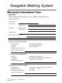


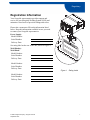


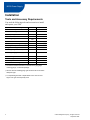
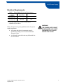

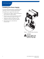


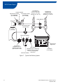

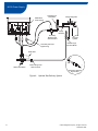
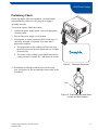
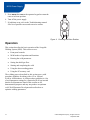
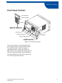


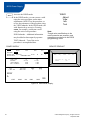
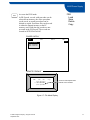


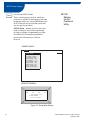

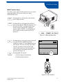
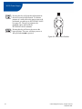
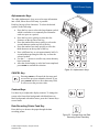
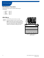


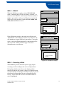
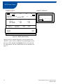


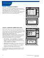
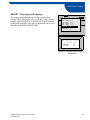
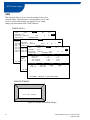

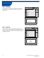


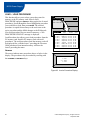
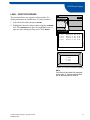
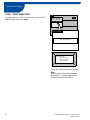
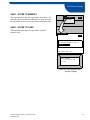

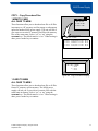
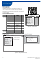
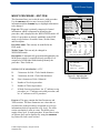


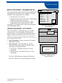
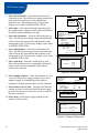

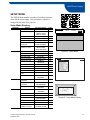
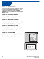

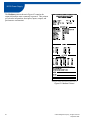


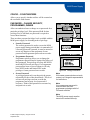
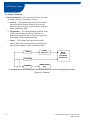
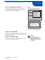


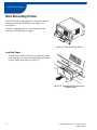
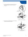

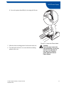
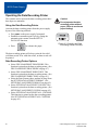
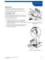

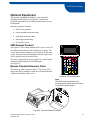


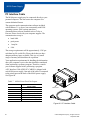
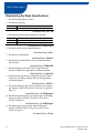
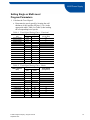


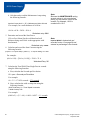


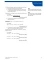

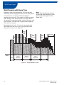

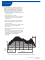
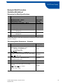
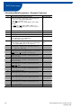
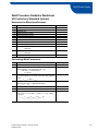


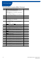


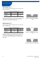
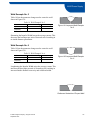


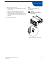

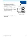


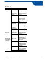
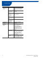

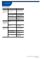
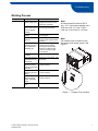


![PDF [1] - Dep SAE Soudage, Automatismes et Electronique location](http://vs1.manualzilla.com/store/data/005888267_1-8c649f384f0a877ffbc023ff9f75566c-150x150.png)