1
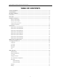
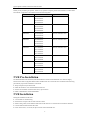
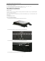
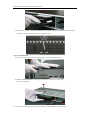
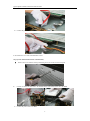
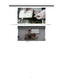
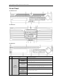
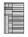
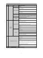
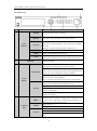
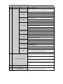
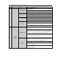
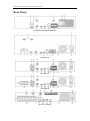
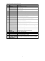
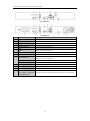
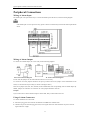
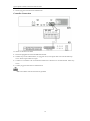
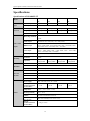
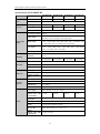
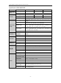
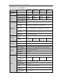
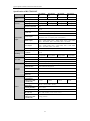
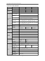
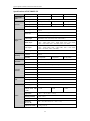
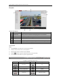
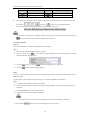
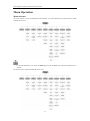
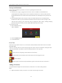
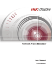
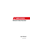
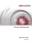
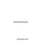
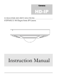
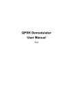
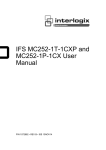
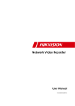
Network Video Recorder Quick Operation Guide UD.6L0202B1353A01 Quick Operation Guide of Network Video Recorder TABLE OF CONTENTS NVR Pre-Installation ....................................................................................................................................... 2 NVR Installation .............................................................................................................................................. 2 Hard Disk Installation ..................................................................................................................................... 3 Front Panel ....................................................................................................................................................... 7 Rear Panel ...................................................................................................................................................... 14 Peripheral Connections ................................................................................................................................. 17 Wiring of Alarm Input .............................................................................................................................. 17 Wiring of Alarm Output ........................................................................................................................... 17 Using of Alarm Connectors ...................................................................................................................... 17 Controller Connection .............................................................................................................................. 18 Specifications .................................................................................................................................................. 19 Specifications of DS-9600NI-ST ............................................................................................................. 19 Specifications of DS-9600NI-RT ............................................................................................................. 20 Specification of DS-9600NI-XT .............................................................................................................. 21 Specifications of DS-8600NI-ST ............................................................................................................. 22 Specification of DS-7700NI-ST ............................................................................................................... 23 Specification of DS-7700NI-SP ............................................................................................................... 24 Specifications of DS-7600NI-ST ............................................................................................................. 24 Specifications of DS-7600NI-SP ............................................................................................................. 26 HDD Storage Calculation Chart ................................................................................................................... 27 Accessing by Web Browser ............................................................................................................................ 28 Logging In................................................................................................................................................ 28 Live View ................................................................................................................................................. 28 Recording ................................................................................................................................................. 29 Playback ................................................................................................................................................... 31 Log ....................................................................................................................................................... 32 Menu Operation ............................................................................................................................................. 33 Menu Structure......................................................................................................................................... 33 Startup and Shutdown .............................................................................................................................. 34 Live View ................................................................................................................................................. 34 Adding IP Cameras .................................................................................................................................. 34 One-touch RAID Configuration ............................................................................................................... 36 Recording ................................................................................................................................................. 37 Instant Recording ............................................................................................................................. 37 All-day Recording ............................................................................................................................ 38 Playback ................................................................................................................................................... 38 Backup ..................................................................................................................................................... 39 1 Quick Operation Guide of Network Video Recorder Thank you for purchasing our product. If there is any question or request, please do not hesitate to contact dealer. This manual is applicable to the models listed in the following table. Series Model Type 9600NI-ST DS-9608NI-ST Network Video Recorder DS-9616NI-ST DS-9632NI-ST DS-9664NI-ST 9600NI-RT DS-9608NI-RT Network Video Recorder DS-9616NI-RT DS-9632NI-RT DS-9664NI-RT 9600NI-XT DS-9616NI-XT Network Video Recorder DS-9632NI-XT DS-9664NI-XT 8600NI-ST DS-8608NI-ST Network Video Recorder DS-8616NI-ST DS-8632NI-ST DS-8664NI-ST 7700NI-ST DS-7708NI-ST Network Video Recorder DS-7716NI-ST DS-7732NI-ST DS-7764NI-ST 7700NI-SP DS-7708NI-SP Network Video Recorder DS-7716NI-SP DS-7732NI-SP 7600NI-ST DS-7608NI-ST Network Video Recorder DS-7616NI-ST DS-7632NI-ST 7600NI-SP DS-7608NI-SP Network Video Recorder DS-7616NI-SP DS-7632NI-SP NVR Pre-Installation The DS-9600/8600/7700/7600NI-ST, DS-9600NI-RT/XT and DS-7700/7600NI-SP series NVR are highly advanced surveillance equipment that should be installed with care. Please take into consideration the following precautionary steps before installation of the NVR. 1. Keep all liquids away from the NVR. 2. Install the NVR in a well-ventilated and dust-free area. 3. Ensure environmental conditions meet factory specifications. 4. Install a manufacturer recommended HDD. NVR Installation During the installation of the NVR: 1. 2. 3. 4. 5. Use brackets for rack mounting. Ensure there is ample room for audio and video cables. When routing cables, ensure that the bend radius of the cables are no less than five times than its diameter. Connect both the alarm and RS-485 cable. Allow at least 2cm (≈0.75-inch) of space between racks mounted devices. 2 Quick Operation Guide of Network Video Recorder 6. Ensure the NVR is grounded. 7. Environmental temperature should be within the range of -10 ºC ~ 55 ºC, 14ºF ~ 131ºF. 8. Environmental humidity should be within the range of 10% ~ 90%. Hard Disk Installation Before you start: Disconnect the power from the NVR before installing a hard disk drive (HDD). A factory recommended HDD should be used for this installation. Up to 8 SATA hard disks can be installed on your NVR. For DS-9600NI-XT, up to 16 SATA hard disks can be installed on it. Tools Required: Screwdriver. Steps (for DS-9600NI-ST/RT/XT): 1. Fasten the hard disk mounting handle to the hard disk with screws. 2. Insert the key and turn in clockwise direction to open the panel lock. 3. Press the buttons on the panel of two sides and open the front panel. 4. Insert the hard disk along the slot until it is placed into position. 3 Quick Operation Guide of Network Video Recorder 5. Repeat the above steps to install other hard disks onto the NVR. After having finished the installation of all hard disks, close the front panel and lock it with the key again. Steps (for DS-8600NI-ST): 1. Remove the cover from the NVR by unfastening the screws on the back and side. 2. Install the HDD in the HDD rack using the provided screws. Fasten the screws on the button to fix the HDD. 3. Connect one end of the data cable to the motherboard of NVR and the other end to the HDD. 4 Quick Operation Guide of Network Video Recorder 4. Connect the power cable to the HDD. 5. Re-install the cover of the NVR and fasten screws. Steps (for DS-7600NI-ST/SP and DS-7700NI-ST/SP): 1. 2. Remove the cover from the NVR by unfastening the screws on the rear and side panel. Connect one end of the data cable to the motherboard of NVR and the other end to the HDD. 3. Connect the power cable to the HDD. 5 Quick Operation Guide of Network Video Recorder 4. Place the HDD on the bottom of the device and then fasten the screws on the bottom to fix the HDD. 6 Quick Operation Guide of Network Video Recorder Front Panel DS-9600NI-ST/RT DS-9600NI-XT DS-8600NI-ST No. Name Function Description ALARM READY Turns red when a sensor alarm is detected. Ready LED is normally blue, indicating that the device is functioning properly. Turns blue when device is controlled by an IR remote. STATUS 1 Status Indicators Turns red when controlled by a keyboard and purple when IR remote and keyboard is used at the same time. HDD Flashes red when data is being read from or written to HDD. MODEM (not for Reserved for future usage. DS-9600NI-XT) TX/RX Flashes blue when network connection is functioning properly. 7 Quick Operation Guide of Network Video Recorder No. Name Function Description Guard LED turns blue when the device is in armed status; at this time, an alarm is enabled when an event is detected. GUARD The LED turns off when the device is unarmed. The arm/disarm status can be changed by pressing and holding on the ESC button for more than 3 seconds in live view mode. 2 3 IR Receiver Receiver for IR remote Front Panel Lock (for DS-9600NI-ST/RT/XT series) 4 DVD-R/W You can lock or unlock the panel by the key. Slot for DVD-R/W. Switch to the corresponding channel in Live view or PTZ Control mode. Input numbers and characters in Edit mode. 5 Alphanumeric Buttons Switch between different channels in Playback mode. The light of the button is blue when the corresponding channel is recording; it is red when the channel is in network transmission status; it is pink when the channel is recording and transmitting. 6 USB Interfaces ESC Universal Serial Bus (USB) ports for additional devices such as USB mouse and USB Hard Disk Drive (HDD). Back to the previous menu. Press for Arming/disarming the device in Live View mode. Enter the Manual Record setting menu. REC/SHOT In PTZ control settings, press the button and then you can call a PTZ preset by pressing Numeric button. It is also used to turn audio on/off in the Playback mode. PLAY/AUTO ZOOM+ The button is used to enter the Playback mode. It is also used to auto scan in the PTZ Control menu. Zoom in the PTZ camera in the PTZ Control setting. Adjust focus in the PTZ Control menu. A/FOCUS+ It is also used to switch between input methods (upper and lowercase alphabet, symbols and numeric input). Edit text fields. When editing text fields, it will also function as 7 Composite a Backspace button to delete the character in front of the cursor. Keys On checkbox fields, pressing the button will tick the checkbox. EDIT/IRIS+ In PTZ Control mode, the button adjusts the iris of the camera. In Playback mode, it can be used to generate video clips for backup. Enter/exit the folder of USB device and eSATA HDD. MAIN/SPOT/ZOO Switch between main and spot output. M- In PTZ Control mode, it can be used to zoom out the image. Select all items on the list when used in a list field. In PTZ Control mode, it will turn on/off PTZ light (if F1/ LIGHT applicable). In Playback mode, it is used to switch between play and reverse play. F2/ AUX Cycle through tab pages. In synchronous playback mode, it is used to switch between 8 Quick Operation Guide of Network Video Recorder No. Name Function Description channels. Press the button will help you return to the Main menu (after successful login). Press and hold the button for 5 seconds will turn off audible key MENU/WIPER beep. In PTZ Control mode, the MENU/WIPER button will start wiper (if applicable). In Playback mode, it is used to show/hide the control interface. Switch between single screen and multi-screen mode. PREV/FOCUS- In PTZ Control mode, it is used to adjust the focus in conjunction with the A/FOCUS+ button. Enter the PTZ Control mode. PTZ/IRIS- In the PTZ Control mode, it is used to adjust the iris of the PTZ camera. The DIRECTION buttons are used to navigate between different fields and items in menus. In the Playback mode, the Up and Down button is used to speed up and slow down recorded video. The Left and Right button DIRECTION will select the next and previous record files. In Live View mode, these buttons can be used to cycle through channels. 8 Control In PTZ control mode, it can control the movement of the PTZ Buttons camera. The ENTER button is used to confirm selection in any of the menu modes. It can also be used to tick checkbox fields. ENTER In Playback mode, it can be used to play or pause the video. In single-frame Playback mode, pressing the button will advance the video by a single frame. In Auto-switch mode, it can be used to stop /start auto switch. Move the active selection in a menu. It will move the selection up and down. In Live View mode, it can be used to cycle through different channels. In the Playback mode: For DS-9600NI-ST/RT/XT series, the 9 JOG SHUTTLE Control ring is used to jump 30s forward/backward in video files. For DS-8600NI-ST series, the outer ring is used to speed up or slow down the record files and the inner ring is used to jump 30s forward/backward in records files. In PTZ control mode, it can control the movement of the PTZ camera. 10 POWER ON/OFF Power on/off switch. 9 Quick Operation Guide of Network Video Recorder DS-7700NI-ST/SP No. Name Function Description POWER Turns green when NVR is powered up. READY The LED is green when the device is running normally. The light is green when the IR remote control is enabled; 1 Status STATUS Indicators The light is red when the function of the composite keys (SHIFT) are used; The light is out when none of the above condition is met. ALARM 2 The light is red when there is an alarm occurring. HDD Blinks red when HDD is reading/writing. Tx/Rx Blinks green when network connection is functioning normally. DVD-R/W Slot for DVD-R/W. In menu mode, the direction buttons are used to navigate between different fields and items and select setting parameters. In playback mode, the Up and Down buttons are used to speed up DIRECTION and slow down record playing, and the Left and Right buttons are used to move the recording 30s forwards or backwards. In the image setting interface, the up and down button can adjust 3 the level bar of the image parameters. Control In live view mode, these buttons can be used to switch channels. Buttons The Enter button is used to confirm selection in menu mode; or used to check checkbox fields and ON/OFF switch. In playback mode, it can be used to play or pause the video. ENTER In single-frame play mode, pressing the Enter button will play the video by a single frame. In auto sequence view mode, the buttons can be used to pause or resume auto sequence. Switch between the numeric or letter input and functions of the SHIFT composite keys. (Input letter or numbers when the light is out; Realize functions when the light is red.) 4 Composite 1/MENU Enter numeral “1”; Access the main menu interface. Keys Enter numeral “2”; 2/ABC/F1 Enter letters “ABC”; The F1 button when used in a list field will select all items in the list. 10 Quick Operation Guide of Network Video Recorder No. Name Function Description In PTZ Control mode, it will turn on/off PTZ light and when the image is zoomed in, the key is used to zoom out. Enter numeral “3”; Enter letters “DEF”; 3/DEF/F2 The F2 button is used to change the tab pages. In PTZ control mode, it zooms in the image. Enter numeral “4”; 4/GHI/ESC Enter letters “GHI”; Exit and back to the previous menu. Enter numeral “5”; Enter letters “JKL”; 5/JKL/EDIT Delete characters before cursor; Check the checkbox and select the ON/OFF switch; Start/stop record clipping in playback. Enter numeral “6”; 6/MNO/PLAY Enter letters “MNO”; Playback, for direct access to playback interface. Enter numeral “7”; 7/PQRS/REC Enter letters “PQRS”; Open the manual record interface. Enter numeral “8”; 8/TUV/PTZ Enter letters “TUV”; Access PTZ control interface. 9/WXYZ/PRE V Enter numeral “9”; Enter letters “WXYZ”; Multi-channel display in live view. Enter numeral “0”; 0/A Shift the input methods in the editing text field. (Upper and lowercase, alphabet, symbols or numeric input). Double press the button to switch the main and auxiliary output. Move the active selection in a menu. It will move the selection up and down. In Live View mode, it can be used to cycle through different channels. 5 JOG SHUTTLE Control In the Playback mode, it can be used to jump 30s forward/backward in video files. In PTZ control mode, it can control the movement of the PTZ camera. 6 POWER ON/OFF 7 USB Interfaces Power on/off switch. Universal Serial Bus (USB) ports for additional devices such as USB mouse and USB Hard Disk Drive (HDD). 11 Quick Operation Guide of Network Video Recorder DS-7600NI-ST/SP: No. Name 1 Function Description USB Interface Connects USB mouse or USB flash memory devices. POWER Turns green when NVR is powered up. READY The LED is green when the device is running normally. The light is green when the IR remote control is enabled; 2 STATUS Status Indicators The light is red when the function of the composite keys (SHIFT) are used; The light is out when none of the above condition is met. ALARM The light is red when there is an alarm occurring. HDD Blinks red when HDD is reading/writing. Tx/Rx Blinks green when network connection is functioning normally. Switch between the numeric or letter input and functions of the 3 SHIFT composite keys. (Input letter or numbers when the light is out; Realize functions when the light is red.) Switch between the numeric or letter input and functions of the SHIFT composite keys. (Input letter or numbers when the light is out; Realize functions when the light is red.) 1/MENU Enter numeral “1”; Access the main menu interface. Enter numeral “2”; Enter letters “ABC”; 2/ABC/F1 The F1 button when used in a list field will select all items in the list. In PTZ Control mode, it will turn on/off PTZ light and when the image is zoomed in, the key is used to zoom out. Enter numeral “3”; 4 Composite Keys 3/DEF/F2 Enter letters “DEF”; The F2 button is used to change the tab pages. In PTZ control mode, it zooms in the image. Enter numeral “4”; 4/GHI/ESC Enter letters “GHI”; Exit and back to the previous menu. Enter numeral “5”; Enter letters “JKL”; 5/JKL/EDIT Delete characters before cursor; Check the checkbox and select the ON/OFF switch; Start/stop record clipping in playback. Enter numeral “6”; 6/MNO/PLAY Enter letters “MNO”; Playback, for direct access to playback interface. 12 Quick Operation Guide of Network Video Recorder No. Name Function Description Enter numeral “7”; 7/PQRS/REC Enter letters “PQRS”; Open the manual record interface. Enter numeral “8”; 8/TUV/PTZ Enter letters “TUV”; Access PTZ control interface. 9/WXYZ/PRE V Enter numeral “9”; Enter letters “WXYZ”; Multi-channel display in live view. Enter numeral “0”; 0/A Shift the input methods in the editing text field. (Upper and lowercase, alphabet, symbols or numeric input). Double press the button to switch the main and auxiliary output. In menu mode, the direction buttons are used to navigate between different fields and items and select setting parameters. In playback mode, the Up and Down buttons are used to speed up DIRECTION and slow down record playing, and the Left and Right buttons are used to move the recording 30s forwards or backwards. In the image setting interface, the up and down button can adjust 5 the level bar of the image parameters. Control In live view mode, these buttons can be used to switch channels. Buttons The Enter button is used to confirm selection in menu mode; or used to check checkbox fields and ON/OFF switch. In playback mode, it can be used to play or pause the video. ENTER In single-frame play mode, pressing the Enter button will play the video by a single frame. In auto sequence view mode, the buttons can be used to pause or resume auto sequence. 13 Quick Operation Guide of Network Video Recorder Rear Panel DS-9600NI-ST/RT and DS-8600NI-ST DS-9600NI-XT DS-7700NI-ST DS-7708NI-SP DS-7716 / 7732NI-SP 14 Quick Operation Guide of Network Video Recorder No. Item Description 1 VIDEO OUT BNC connector for video output. 2 CVBS AUDIO OUT BNC connector for audio output. This connector is synchronized with CVBS video output. VGA AUDIO OUT BNC connector for audio output. This connector is synchronized with VGA video output. 3 LINE IN BNC connector for audio input. 4 RS-232 Interface Connector for RS-232 devices. 5 VGA DB9 connector for VGA output. Display local video output and menu. 6 HDMI HDMI video output connector. 7 eSATA (Optional) Connects external SATA HDD, CD/DVD-RM. 2 eSATA interfaces for DS-9600NI-XT. 8 LAN Interface 1 network interface provided for DS-7700NI-ST/SP and 2 network interfaces for DS-9600NI-ST/RT/XT and DS-8600NI-ST. 9 Termination Switch RS-485 termination switch. Up position is not terminated. Down position is terminated with 120Ω resistance. RS-485 Interface Connector for RS-485 devices. T+ and T- pins connect to R+ and Rpins of PTZ receiver respectively. D+, D- pin connects to Ta, Tb pin of controller. For cascading devices, Controller Port the first NVR’s D+, D- pin should be connected with the D+, D- pin of ALARM IN Connector for alarm input. ALARM OUT Connector for alarm output. 11 GROUND Ground(needs to be connected when NVR starts up). 12 AC 100V ~ 240V AC 100V ~ 240V power supply. 13 POWER Switch for turning on/off the device. 14 USB interface Universal Serial Bus (USB) ports for additional devices such as USB 10 the next NVR. mouse and USB Hard Disk Drive (HDD). Network Interfaces with 15 PoE function (supported Network interfaces for the cameras and to provide power over Ethernet. by DS-7700NI-SP) 15 Quick Operation Guide of Network Video Recorder DS-7600NI-ST DS-7600NI-SP No. Item Description 1 VIDEO OUT BNC connector for video output. 2 AUDIO OUT BNC connector for audio output. 3 AUDIO IN BNC connector for audio input. (Also for two-way audio) 4 RS-232 Interface Connector for RS-232 devices. 5 VGA DB9 connector for VGA output. Display local video output and menu. 6 HDMI HDMI video output connector. 7 USB Connects USB disks and devices. 8 LAN Interface 1 network interface. RS-485 Interface 9 Connector for RS-485 devices. T+ and T- pins connect to R+ and Rpins of PTZ receiver respectively. ALARM IN Connector for alarm input. ALARM OUT Connector for alarm output. 10 Power Supply 12VDC power supply. 11 Power Switch Switch for turning on/off the device. 12 Ground Ground (needs to be connected when NVR starts up). Network Interfaces with 13 PoE function (supported Network interfaces for the cameras and to provide power over Ethernet. by DS-7600NI-SP) 16 Quick Operation Guide of Network Video Recorder Peripheral Connections Wiring of Alarm Input The alarm input is an open/closed relay. To connect the alarm input to the device, use the following diagram. If the alarm input is not an open/close relay, please connect an external relay between the alarm input and the device. Wiring of Alarm Output To connect to an alarm output (AC or DC load), use the following diagram: DC Load Connection Diagram AC Load Connection Diagram For DC load, the jumpers can be used within the limit of 12V/1A safely. To connect an AC load, jumpers should be left open (you must remove the jumper on the motherboard in the NVR). Use an external relay for safety (as shown in the figure above). There are 4 jumpers (JP1, JP2, JP3, and JP4) on the motherboard, each corresponding with one alarm output. By default, jumpers are connected. To connect an AC load, jumpers should be removed. Example: If you connect an AC load to the alarm output 3 of the NVR, then you must remove the JP 3. Using of Alarm Connectors To connect alarm devices to the NVR: 1. Disconnect pluggable block from the ALARM IN /ALARM OUT terminal block. 2. Unfasten stop screws from the pluggable block, insert signal cables into slots and fasten stop screws. Ensure signal cables are in tight. 17 Quick Operation Guide of Network Video Recorder 3. Connect pluggable block back into terminal block. Controller Connection To connect a controller to the NVR: 1. Disconnect pluggable block from the KB terminal block. 2. Unfasten stop screws from the KB D+, D- pluggable block, insert signal cables into slots and fasten stop screws. Ensure signal cables are in tight. 3. Connect Ta on controller to D+ on terminal block and Tb on controller to D- on terminal block. Fasten stop screws. 4. Connect pluggable block back into terminal block. Make sure both the controller and NVR are grounded. 18 Quick Operation Guide of Network Video Recorder Specifications Specifications of DS-9600NI-ST Model DS-9608NI- DS-9616NI- DS-9632NI- DS-9664NI- ST ST ST ST 16-ch 32-ch 64-ch Video/Audio IP video input 8-ch input Two-way audio 1-ch, BNC (2.0 Vp-p, 1kΩ) Incoming bandwidth 40Mbps 80Mbps 160Mbps 160Mbps Outgoing bandwidth 240Mbps 240Mbps 160Mbps 160Mbps Remote Connection 128 Network Recording resolution 5MP /3MP /1080P /UXGA /720P /VGA /4CIF /DCIF /2CIF /CIF /QCIF CVBS output 1-ch, BNC (1.0 Vp-p, 75 Ω) Resolution: 704 ×576 (PAL); 704 × 480 (NTSC) HDMI output 1-ch, resolution: 1920 × 1080P /60Hz, 1920×1080P /50Hz, 1600 × 1200/60Hz, 1280 × 1024 /60Hz, 1280 × 720 /60Hz, 1024 × 768 /60Hz VGA output 1-ch, resolution: 1920 × 1080P /60Hz, 1600 × 1200 /60Hz, 1280 × 1024 /60Hz, 1280 ×720 /60Hz, 1024 ×768 /60Hz Audio output 2-ch, BNC (Linear, 600Ω) Live view / Playback resolution 5MP /3MP /1080P /UXGA /720P /VGA /4CIF /DCIF /2CIF /CIF /QCIF Capability 8-ch@720P, 4-ch@1080P SATA 8 SATA interfaces for 4 HDDs + 1 DVD-R/W (default), or 8HDDs eSATA 1 eSATA interface Capacity Up to 4TB capacity for each HDD Network interface 2 RJ-45 10 /100 /1000 Mbps self-adaptive Ethernet interfaces External Serial interface RS-232; RS-485; Keyboard; interface USB interface 3 × USB 2.0 Alarm in/out 16/4 Power supply 100 ~ 240 VAC, 6.3 A, 50 ~ 60 Hz Consumption (without hard disk or DVD-R/W) ≤ 35 W Working temperature -10 ºC ~ +55 ºC (14ºF ~ 131ºF) Working humidity 10 % ~ 90 % Chassis 19-inch rack-mounted 2U chassis Dimensions (W × D × H) 445 × 470 ×90 mm (17.5" ×18.5"× 3.5") Weight (without hard disk or DVD-R/W) ≤ 8 Kg (17.64 lb) Video/Audio output Decoding Hard disk Others 16-ch@720P, 8-ch@1080P ≤ 40 W 19 16-ch@720P, 8-ch@1080P ≤ 45 W 16-ch@720P, 8-ch@1080P ≤ 45 W Quick Operation Guide of Network Video Recorder Specifications of DS-9600NI-RT DS-9608NI-R T DS-9616NI-R T DS-9632NI-R T DS-9664NI-R T IP video input 8-ch 16-ch 32-ch 64-ch Two-way audio 1-ch, BNC (2.0 Vp-p, 1kΩ) Incoming bandwidth 40Mbps 80Mbps 160Mbps 160Mbps Outgoing bandwidth 240Mbps 240Mbps 160Mbps 160Mbps Remote Connection 128 Model Video/Audio input Network Recording resolution CVBS output Video/Audio output Decoding Hard disk Disk array External interface HDMI output 1-ch, resolution: 1920 × 1080P /60Hz, 1920×1080P /50Hz, 1600 × 1200/60Hz, 1280 × 1024 /60Hz, 1280 × 720 /60Hz, 1024 ×768 /60Hz VGA output 1-ch, resolution: 1920 × 1080P /60Hz, 1600 × 1200 /60Hz, 1280 × 1024 /60Hz, 1280 ×720 /60Hz, 1024 ×768 /60Hz Audio output 2-ch, BNC (Linear, 600Ω) Live view / Playback resolution 5MP /3MP /1080P /UXGA /720P /VGA /4CIF /DCIF /2CIF /CIF /QCIF Capability 8-ch@720P, 4-ch@1080P SATA 8 SATA interfaces for 4 HDDs + 1 DVD-R/W (default), or 8HDDs eSATA 1 eSATA interface Capacity Up to 4TB capacity for each HDD Array type RAID0, RAID1, RAID5, RAID10 Number of array 4 Number of virtual disk 8 Network interface 2 RJ-45 10 /100 /1000 Mbps self-adaptive Ethernet interfaces Serial interface RS-232; RS-485; Keyboard; USB interface 3 × USB 2.0 Alarm in/out 16/4 Power supply 100 ~ 240 VAC, 6.3 A, 50 ~ 60 Hz Consumption (without hard disk or DVD-R/W) Working temperature Others 5MP /3MP /1080P /UXGA /720P /VGA /4CIF /DCIF /2CIF /CIF /QCIF 1-ch, BNC (1.0 Vp-p, 75 Ω) Resolution: 704 ×576 (PAL); 704 × 480 (NTSC) ≤ 35 W 16-ch@720P, 8-ch@1080P ≤ 40 W ≤ 45 W -10 ºC ~ +55 ºC (14ºF ~ 131ºF) Working humidity 10 % ~ 90 % Chassis 19-inch rack-mounted 2U chassis Dimensions (W × D × H) Weight (without hard disk or DVD-R/W) 16-ch@720P, 8-ch@1080P 445 × 470 ×90 mm (17.5" ×18.5"× 3.5") ≤ 8 Kg (17.64 lb) 20 16-ch@720P, 8-ch@1080P ≤ 45 W Quick Operation Guide of Network Video Recorder Specification of DS-9600NI-XT Model Video/Audio input Network DS-9616NI-XT DS-9632NI-XT DS-9664NI-XT IP video input 16-ch 32-ch 64-ch Two-way audio 1-ch, BNC (2.0 Vp-p, 1kΩ) Incoming bandwidth 80Mbps 160Mbps 160Mbps Outgoing bandwidth 240Mbps 160Mbps 160Mbps Remote Connection 128 Recording resolution CVBS output Video/Audio output Decoding Hard disk 5MP /3MP /1080P /UXGA /720P /VGA /4CIF /DCIF /2CIF /CIF /QCIF 1-ch, BNC (1.0 Vp-p, 75 Ω) Resolution: 704 ×576 (PAL); 704 × 480 (NTSC) HDMI output 1-ch, resolution: 1920 × 1080P /60Hz, 1920×1080P /50Hz, 1600 × 1200/60Hz, 1280 × 1024 /60Hz, 1280 × 720 /60Hz, 1024 ×768 /60Hz VGA output 1-ch, resolution: 1920 × 1080P /60Hz, 1600 × 1200 /60Hz, 1280 × 1024 /60Hz, 1280 × 720 /60Hz, 1024 ×768 /60Hz Audio output 2-ch, BNC (Linear, 600Ω) Live view / Playback resolution 5MP /3MP /1080P /UXGA /720P /VGA /4CIF /DCIF /2CIF /CIF /QCIF Capability 16-ch@720P, 8-ch@1080P SATA 16 SATA interfaces for 16 HDDs eSATA 2 eSATA interfaces Capacity Up to 4TB capacity for each HDD Array type RAID0, RAID1, RAID5, RAID10 Number of array 16 Network interface 2 RJ-45 10 /100 /1000 Mbps self-adaptive Ethernet interfaces Serial interface RS-232; RS-485; Keyboard; USB interface 3 × USB 2.0 Alarm in 16 Alarm out 4 Power supply 100 ~ 240 VAC, 6.3 A, 50 ~ 60 Hz Consumption (without hard disks) Working temperature ≤ 45 W Working humidity 10 % ~ 90 % Chassis 19-inch rack-mounted 3U chassis Dimensions (W × D × H) 445 × 496 ×146 mm (17.5" ×19.5"× 5.7") Weight (without hard disks) ≤ 12.5 Kg (27.56 lb) Disk array External interface Others -10 ºC ~ +55 ºC (14ºF ~ 131ºF) 21 Quick Operation Guide of Network Video Recorder Specifications of DS-8600NI-ST DS-8608NIST DS-8616NIST DS-8632NIST DS-8664NIST IP video input 8-ch 16-ch 32-ch 64-ch Two-way audio 1-ch, BNC (2.0 Vp-p, 1kΩ) Incoming bandwidth 40Mbps 80Mbps 160Mbps 160Mbps Outgoing bandwidth 240Mbps 240Mbps 160Mbps 160Mbps Remote Connection 128 Recording resolution 5MP /3MP /1080P /UXGA /720P /VGA /4CIF /DCIF /2CIF /CIF /QCIF CVBS output 1-ch, BNC (1.0 Vp-p, 75 Ω) Resolution: 704 ×576 (PAL); 704 × 480 (NTSC) HDMI output 1-ch, resolution: 1920 × 1080P /60Hz, 1920 × 1080P /50Hz, 1600 × 1200 /60Hz, 1280 ×1024 /60Hz, 1280 × 720 /60Hz, 1024 ×768 /60Hz VGA output 1-ch, resolution: 1920 × 1080P /60Hz, 1600 × 1200 /60Hz, 1280 × 1024 /60Hz, 1280 ×720 /60Hz, 1024 ×768 /60Hz Audio output 2-ch, BNC (Linear, 600Ω) Live view / Playback resolution 5MP /3MP /1080P /UXGA /720P /VGA /4CIF /DCIF /2CIF /CIF /QCIF Capability 8-ch@720P, 4-ch@1080P SATA 8 SATA interfaces for 4 HDDs + 1 DVD-R/W (default), or 8HDDs eSATA 1 eSATA interface Capacity Up to 4TB capacity for each HDD Network interface 2 RJ-45 10 /100 /1000 Mbps self-adaptive Ethernet interfaces Serial interface RS-232; RS-485; Keyboard; USB interface 3 × USB 2.0 Alarm in/out 16/4 Power supply 100 ~ 240 VAC, 6.3 A, 50 ~ 60 Hz Consumption (without hard disk or DVD-R/W) ≤ 35 W Working temperature -10 ºC ~ +55 ºC (14ºF ~ 131ºF) Working humidity 10 % ~ 90 % Chassis 19-inch rack-mounted 2U chassis Model Video/Audio input Network Video/Audio output Decoding Hard disk External interface Others Dimensions (W × D × H) Weight (without hard disk or DVD-R/W) 16-ch@720P, 8-ch@1080P ≤ 40 W 16-ch@720P, 8-ch@1080P ≤ 45 W 445 × 470 ×90 mm (17.5" ×18.5"× 3.5") ≤ 8 Kg (17.64 lb) 22 16-ch@720P, 8-ch@1080P ≤ 45 W Quick Operation Guide of Network Video Recorder Specification of DS-7700NI-ST IP video input DS-7708NIST 8-ch Two-way audio 1-ch, BNC (2.0 Vp-p, 1kΩ) Incoming bandwidth 40Mbps 80Mbps 160Mbps 160Mbps Outgoing bandwidth 240Mbps 240Mbps 160Mbps 160Mbps Remote Connection 128 Recording resolution 5MP /3MP /1080P /UXGA /720P /VGA /4CIF /DCIF /2CIF /CIF /QCIF Model Video/Audio input Network Frame rate External interface Main stream: 25 fps (P) / 30 fps (N) Sub-stream: 25 fps (P) / 30 fps (N) HDMI output 1-ch, resolution: 1920 × 1080P /60Hz, 1920 × 1080P /50Hz, 1600 × 1200 /60Hz, 1280 ×1024 /60Hz, 1280 × 720 /60Hz, 1024 ×768 /60Hz VGA output 1-ch, resolution: 1920 × 1080P /60Hz, 1600 × 1200 /60Hz, 1280 × 1024 /60Hz, 1280 ×720 /60Hz, 1024 ×768 /60Hz Audio output 2-ch, BNC (Linear, 600Ω) Live view / Playback resolution 5MP /3MP /1080P /UXGA /720P /VGA /4CIF /DCIF /2CIF /CIF /QCIF 8-ch@720P, 16-ch@720P, 16-ch@720P, 16-ch@720P, 4-ch@1080P 8-ch@1080P 8-ch@1080P 8-ch@1080P SATA 4 SATA interfaces for 2 HDDs + 1 DVD-R/W (default), or 4HDDs eSATA 1 eSATA interface Capacity Up to 4TB capacity for each HDD Network interface 1 RJ-45 10 /100 /1000 Mbps self-adaptive Ethernet interface Serial interface RS-232; RS-485; Keyboard USB interface 3 × USB 2.0 Alarm in 16 Alarm out 4 Power supply 100 ~ 240 VAC, 6.3 A, 50 ~ 60 Hz Consumption (without hard disk or DVD-R/W) Working temperature Others DS-7764NIST 64-ch 1-ch, BNC (1.0 Vp-p, 75 Ω) Resolution: 704 ×576 (PAL); 704 × 480 (NTSC) Capability Hard disk DS-7732NIST 32-ch CVBS output Video/Audio output Decoding DS-7716NIST 16-ch ≤ 35 W ≤ 40W ≤ 45 W -10 ºC ~ +55 ºC (14ºF ~ 131ºF) Working humidity 10 % ~ 90 % Chassis 19-inch rack-mounted 1.5U chassis Dimensions (W × D × H) Weight (without hard disk or DVD-R/W ) 445 × 390 ×70 mm ( 17.5"× 15.3" × 2.8") ≤ 4 Kg (8.82 lb) 23 ≤ 45 W Quick Operation Guide of Network Video Recorder Specification of DS-7700NI-SP Model Video/Audio input Network DS-7708NI-SP DS-7716NI-SP DS-7732NI-SP IP video input 8-ch 16-ch 32-ch Two-way audio 1-ch, BNC (2.0 Vp-p, 1kΩ) Incoming bandwidth 40Mbps 80Mbps 160Mbps Outgoing bandwidth 240Mbps 240Mbps 160Mbps Remote Connection 128 Record resolution 5MP /3MP /1080P /UXGA /720P /VGA /4CIF /DCIF /2CIF /CIF /QCIF Main stream: 25 fps (P) / 30 fps (N) Frame rate Sub-stream: 25 fps (P) / 30 fps (N) Video/Audio output Decoding CVBS output 1-ch, BNC (1.0 Vp-p, 75 Ω) Resolution: 704 ×576 (PAL); 704 × 480 (NTSC) HDMI output 1-ch, resolution: 1920 × 1080P /60Hz, 1920 × 1080P /50Hz, 1600 × 1200 /60Hz, 1280 ×1024 /60Hz, 1280 × 720 /60Hz, 1024 ×768 /60Hz VGA output 1-ch, resolution: 1920 × 1080P /60Hz, 1600 × 1200 /60Hz, 1280 × 1024 /60Hz, 1280 ×720 /60Hz, 1024 ×768 /60Hz Audio output 2-ch, BNC (Linear, 600Ω) Live view / Playback resolution 5MP /3MP /1080P /UXGA /720P /VGA /4CIF /DCIF /2CIF /CIF /QCIF 8-ch@720P, 16-ch@720P, 16-ch@720P, 4-ch@1080P 8-ch@1080P 8-ch@1080P Capability Hard disk External interface SATA 4 SATA interfaces for 2 HDDs + 1 DVD-R/W (default), or 4HDDs eSATA 1 eSATA interface Capacity Up to 4TB capacity for each HDD Network interface 1 RJ-45 10 /100 /1000 Mbps self-adaptive Ethernet interface Serial interface RS-232; RS-485; Keyboard USB interface 3 × USB 2.0 Alarm in 16 Alarm out 4 Interface 8 independent 100 Mbps PoE network interfaces 16 independent 100 Mbps PoE network interfaces Max. Power 180W 200W Supported standard AT and AF Power supply 100 ~ 240 VAC, 6.3 A, 50 ~ 60 Hz PoE Consumption (without hard disk, DVD-R/W or PoE) Working temperature Others ≤ 35W ≤ 40W -10 ºC ~ +55 ºC (14ºF ~ 131ºF) Working humidity 10 % ~ 90 % Chassis Dimensions (W × D × H) Weight (without hard disk or DVD-R/W) 19-inch rack-mounted 1.5U chassis 445 × 390 ×70 mm ( 17.5" × 15.3" × 2.8") ≤ 4 Kg (8.8 lb) 24 ≤ 45W Quick Operation Guide of Network Video Recorder Specifications of DS-7600NI-ST Model Video/Audio input Network DS-7608NI-ST DS-7616NI-ST DS-7632NI-ST IP video input 8-ch 16-ch 32-ch Two-way audio 1-ch, BNC (2.0 Vp-p, 1kΩ) Incoming bandwidth 40Mbps 80Mbps 160Mbps Outgoing bandwidth 240Mbps 240Mbps 160Mbps Remote Connection 128 Recording resolution 5MP /3MP /1080P /UXGA /720P /VGA /4CIF /DCIF /2CIF /CIF /QCIF Main stream: 25 fps (P) / 30 fps (N) Frame rate Sub-stream: 25 fps (P) / 30 fps (N) Video/Audio output Decoding CVBS output 1-ch, BNC (1.0 Vp-p, 75 Ω) Resolution: 704 ×576 (PAL); 704 × 480 (NTSC) HDMI output 1-ch, resolution: 1920 × 1080P /60Hz, 1920 × 1080P /50Hz, 1600 × 1200 /60Hz, 1280 ×1024 /60Hz, 1280 × 720 /60Hz, 1024 ×768 /60Hz VGA output 1-ch, resolution: 1920 × 1080P /60Hz, 1600 × 1200 /60Hz, 1280 × 1024 /60Hz, 1280 ×720 /60Hz, 1024 ×768 /60Hz Audio output 1-ch, BNC (Linear, 600Ω) Playback resolution 5MP /3MP /1080P /UXGA /720P /VGA /4CIF /DCIF /2CIF /CIF /QCIF Synchronous playback Live view / Playback resolution Capability 8-ch 16-ch 16-ch 5MP /3MP /1080P /UXGA /720P /VGA /4CIF /DCIF /2CIF /CIF /QCIF 8-ch@720P, 16-ch@720P, 16-ch@720P, 4-ch@1080P 8-ch@1080P 8-ch@1080P SATA 2 SATA interfaces Capacity Each interface supports up to 4TB capacity for recording Network interface 1 RJ-45 10 /100 /1000 Mbps self-adaptive Ethernet interface Serial interface RS-232; RS-485; USB interface 2 × USB 2.0 Alarm in 4 Alarm out 2 Power supply 12 VDC Consumption (without hard disk) ≤ 13 W Working temperature -10 ºC ~ +55 ºC (14ºF ~ 131ºF) Working humidity 10 % ~ 90 % Chassis 19-inch rack-mounted 1U chassis Dimensions (W × D × H) 445 × 261 ×44.5 mm (17.5" ×10.3" × 1.8") Weight (without hard disk) ≤ 4 Kg (8.82 lb) Hard disk External interface Others 25 Quick Operation Guide of Network Video Recorder Specifications of DS-7600NI-SP Model Video/Audio input Network DS-7608NI-SP DS-7616NI-SP DS-7632NI-SP IP video input 8-ch 16-ch 32-ch Two-way audio 1-ch, BNC (2.0 Vp-p, 1kΩ) Incoming bandwidth 40Mbps 80Mbps 160Mbps Outgoing bandwidth 240Mbps 240Mbps 160Mbps Remote Connection 128 Recording resolution 5MP /3MP /1080P /UXGA /720P /VGA /4CIF /DCIF /2CIF /CIF /QCIF Main stream: 25 fps (P) / 30 fps (N) Frame rate Sub-stream: 25 fps (P) / 30 fps (N) CVBS output 1-ch, BNC (1.0 Vp-p, 75 Ω) Resolution: 704 ×576 (PAL); 704 × 480 (NTSC) HDMI output 1-ch, resolution: 1920 × 1080P /60Hz, 1920 × 1080P /50Hz, 1600 × 1200 /60Hz, 1280 ×1024 /60Hz, 1280 × 720 /60Hz, 1024 ×768 /60Hz VGA output 1-ch, resolution: 1920 × 1080P /60Hz, 1600 × 1200 /60Hz, 1280 × 1024 /60Hz, 1280 ×720 /60Hz, 1024 ×768 /60Hz Audio output 1-ch, BNC (Linear, 600Ω) Live view / Playback resolution 5MP /3MP /1080P /UXGA /720P /VGA /4CIF /DCIF /2CIF /CIF /QCIF 8-ch@720P, 16-ch@720P, 16-ch@720P, 4-ch@1080P 8-ch@1080P 8-ch@1080P Video/Audio output Decoding Capability SATA 2 SATA interfaces Capacity Up to 4TB capacity for each HDD Network interface 1 RJ-45 10 /100 /1000 Mbps self-adaptive Ethernet interface Serial interface RS-232; RS-485; USB interface 2 × USB 2.0 Alarm in 4 Alarm out 2 Interface 8 independent 100 Mbps PoE network interfaces Consumption 120W Standard AF Power supply 100 ~ 240 VAC, 6.3 A, 50 ~ 60 Hz Consumption (without hard disk or PoE) ≤ 35W Working temperature -10 ºC ~ +55 ºC (14 ºF ~ 131 ºF) Working humidity 10 % ~ 90 % Chassis 19-inch rack-mounted 1U chassis Dimensions (W × D × H) 445 × 261 ×44.5 mm (17.5" ×10.3" × 1.8") Weight (without hard disk) ≤ 4 Kg (8.82 lb) Hard disk External interface PoE Others ≤ 40W 26 ≤ 45W Quick Operation Guide of Network Video Recorder HDD Storage Calculation Chart The following chart shows an estimation of storage space used based on recording at one channel for an hour at a fixed bit rate. Bit Rate 96K 128K 160K 192K 224K 256K 320K 384K 448K 512K 640K 768K 896K 1024K 1280K 1536K 1792K 2048K Storage Used 42M 56M 70M 84M 98M 112M 140M 168M 196M 225M 281M 337M 393M 450M 562M 675M 787M 900M 4096K 1800M 8192K 3600M 16384K 7200M Please note that supplied values for storage space used is just for reference. The storage values in the chart are estimated by formulas and may have some deviation from actual value. 27 Quick Operation Guide of Network Video Recorder Accessing by Web Browser Logging In You can get access to the device via web browser. Open web browser, input the IP address of the device and then press Enter. The login interface appears. Input the user name and password, and click the Login button. The default IP address is 192.0.0.64. The default user name is admin, and password is 12345. You may use one of the following listed web browsers: Internet Explorer 6.0, Internet Explorer 7.0, Internet Explorer 8.0, Internet Explorer 9.0, Internet Explorer 10.0, Apple Safari, Mozilla Firefox, and Google Chrome. The supported resolutions include 1024*768 and above. When you log in for the first time, the system will remind you to install the Plug-in control. After the installation, you can configure and manage the device remotely. Live View The live view interface appears by default when you log in the device. 28 Quick Operation Guide of Network Video Recorder Interface Introduction No. Name Description Displays the list of channels and the playing and recording status of each channel. Channel List 1 The stream type can be switched by clicking the icon before the channel name: stands for main stream and for sub-stream. 2 Live View Window Displays the image of channel, and multi-window division is supported. 3 Play Control Bar Play control operations are supported. Pan, tilt, zoom operations are supported, as well as preset and patrol editing PTZ Control 4 and calling. PTZ function can only be realized if the connected camera supports PTZ control. Video Parameters 5 Configuration Brightness, contrast, saturation and hue of the image can be edited. Start Live View Steps: 1. In the live view window, select a playing window by clicking the mouse. 2. Double click a camera from the device list to start the live view. 3. You can click the button on the toolbar to start the live view of all cameras on the device list. Refer to the following table for the description of buttons on the live view window: Icon Description Icon Select the window-division mode / / Start/Stop all live view / Capture pictures in the live view Start/Stop all recording / Previous/Next page Open/Close audio Start/Stop two-way Audio Adjust volume mode / Description / Enable/Disable digital zoom Full screen Recording Before you start Make sure the device is connected with HDD or network disk, and the HDD or network disk has been initialized for the first time to use. Two recording types can be configured: Manual and Scheduled. The following section introduces the configuration of scheduled recording. Steps: 1. Click Remote Configuration> Camera Settings> Record Schedule to enter Record Schedule settings interface. 2. Select the camera to configure the record schedule. 29 Quick Operation Guide of Network Video Recorder 3. Check the checkbox of Enable Schedule to enable recording schedule. 4. Choose the day in a week to configure scheduled recording. 5. Click Edit to edit record schedule. 1) Configure All Day or Customize Record: If you want to configure the all-day recording, please check the All Day checkbox. If you want to record in different time sections, check the Customize checkbox. Set the Start Time and End Time. Up to 8 segments can be configured and each segment cannot be overlapped. 2) Select a Record Type. The record type can be Continuous, Motion, Alarm, Motion & Alarm, Motion | Alarm and VCA. 3) Check the checkbox of Select All and click Copy to copy settings of this day to the whole week. You can also check any of the checkboxes before the date and click Copy. 4) Click OK to save the settings and exit the Edit Schedule interface. 6. Click Advanced to configure advanced record parameters. 7. Click Save to validate the above settings. 8. (Optional) You can click the Copy to… button to copy the same setting to other cameras. 30 Quick Operation Guide of Network Video Recorder Playback Interface Introduction No. Name Description 1 Channel List Displays the list of channels and the playing status of each channel. 2 Playback Window Displays the image of channel. 3 Play Control Bar Play control operations are supported. 4 Time Line Displays the time bar and the records marked with different colors. 5 Playback Status Displays the playback status, including channel number and playback speed. 6 Calendar You can select the date to play. Start Playback Steps: 1. Click Playback on the menu bar to enter playback interface. 2. Click the camera from the device list for playback. 3. Select the date from the calendar and click Search. 4. Click the 5. Use the buttons on the toolbar to operate in playback mode. button to play the searched video file on the current date. Playback Control Buttons Description Area Description / Play/Pause Stop Slow down Speed up Play by single frame Capture Stop all playback Download / Area Video clip / 31 Description Open/Close audio Quick Operation Guide of Network Video Recorder Area 6. Description Area Description Full screen Transcoded playback Reverse playback Window division You can drag the progress bar with the mouse to locate the exact playback point. You can also input the time in the textbox and click button to locate the playback point. The color of the video on the progress bar stands for the different video types. To play back recording files from different channel, you may set the window division mode by clicking the button and choose a window, and then repeat the above steps 2-4. Transcoded Playback Purpose: To save the bandwidth cost, the transcoded playback can be adopted. Steps: 1. Make sure the playback of current channel is stopped. 2. Move the mouse to the icon and edit the required parameters for transcoded playback, including Resolution, Bitrate, and Frame Rate. 3. Click the button, if it turns to , then the trancoding process is compeleted. 4. Click the button to start transcoded playback. Log You can view and export the log files at any time, including operation, alarm, exception and information of device. Before you start: The Log function can be realized only when the device is connected with HDD or network disk. Steps: 2. Click Log on the menu bar to enter the Log interface. 3. Set the log search conditions to refine your search, including the Major Type, Minor Type, Start Time and End Time. 4. Click the Search button to start searching log files. 5. The matched log files will be displayed on the list. Up to 2000 log files can be found each time, and 100 log files can be displayed on each page. You can click the button to save the searched log files to local directory. 32 Quick Operation Guide of Network Video Recorder Menu Operation Menu Structure The menu structure of the DS-9600/8600/7700/7600NI-ST, DS-7700/7600NI-SP and DS-9600NI-XT (RAID disabled) Series NVR: For the DS-9600NI-XT series NVR, the RAID apperas under the HDD menu when the RAID function is enabled. The menu structure of the DS-9600NI-RT Series NVR: 33 Quick Operation Guide of Network Video Recorder Startup and Shutdown Proper startup and shutdown procedures are crucial to expanding the life of the NVR. To start your NVR: 1. Check the power supply is plugged into an electrical outlet. It is HIGHLY recommended that an Uninterruptible Power Supply (UPS) be used in conjunction with the device. The Power button (for the DS-9600 and DS-8600 series NVR) on the front panel should be red, indicating the device gets the power supply. 2. Press the POWER button on the front panel. The Power LED should turn blue (for the DS-9600 and DS-8600 series NVR) or green (for the DS-7700 and DS-7600 series NVR). The unit will begin to start. After the device starting up, the wizard will guide you through the initial settings, including modifying password, date and time settings, network settings, HDD initializing, and recording. To shut down the NVR: 1. Enter the Shutdown menu. Menu > Shutdown 2. Select the Shutdown button. 3. Click the Yes button. Live View Some icons are provided on screen in Live View mode to indicate different camera status. These icons include: Live View Icons In the live view mode, there are icons at the upper-right corner of the screen for each channel, showing the status of the record and alarm in the channel, so that you can find problems as soon as possible. Alarm (video loss, tampering, motion detection or sensor alarm) Record (manual record, schedule record, motion detection or alarm triggered record) Alarm & Record Event/Exception (event and exception information, appears at the lower-left corner of the screen.) Adding IP Cameras You should add and configure the online IP cameras to enable the live view and recording function. Steps: 1. Right-click the mouse when you in the live view mode to show the right-click menu. 34 Quick Operation Guide of Network Video Recorder 2. Select Add IP Camera in the pop-up menu to enter the IP Camera Management interface. 3. The online cameras with same network segment will be displayed in the camera list. Click the add the camera. button to Or you can click the One-couch Adding button to add all the online IP cameras. The added camera is marked in white while the camera has not been added is marked in yellow. Explanation of the icons Icon Explanation Icon Edit basic parameters of the camera Explanation Add the detected IP camera. The camera is disconnected; you can The camera is connected. click the icon to get the exception information of camera. Delete the IP camera 4. Advanced settings of the camera. To add other IP cameras: 35 Quick Operation Guide of Network Video Recorder 1) Click the Custom Adding button to pop up the Add IP Camera (Custom) interface. 2) You can edit the IP address, protocol, management port, and other information of the IP camera to be added. 3) Click Add to add the camera. 4) (For the encoders with multiple channels only) check the checkbox of Channel No. in the pop-up window, as shown in the following figure, and click OK to finish adding. One-touch RAID Configuration Purpose: For the DS-9600NI-RT/XT series NVR, the disk array must be configured if you want to save recording and log files locally. Through one-touch configuration, you can quickly create the disk array. By default, the array type to be created is RAID 5. Before you start: As the default array type is RAID 5, at least 3 HDDs must be installed in you device. Steps: 1. (For DS-9600NI-XT series only) Enable the RAID function by checking the checkbox in the disk mode configuration interface. Menu > HDD > Advanced 2. Enter the Physical Disk Settings interface. Menu > HDD > RAID 36 Quick Operation Guide of Network Video Recorder 3. Click One-touch Configuration to enter the One-touch Array Configuration interface. 4. Edit the array name in the Array Name text filed and click OK button to start configuring array. If you install 4 HDDs or above for one-touch configuration, a hot spare disk will be set by default. It is recommended to set hot spare disk for automatically rebuilding the array when the array is abnormal. 5. When the array configuration is completed, click OK button in the pop-up message box to finish the settings. Recording Before you start: Make sure that the HDD has already been installed. If not, please install a HDD and initialize it. You may refer to the user manual for detailed information. Purpose: Two kinds of record types are introduced in the following section, including Instant Record and All-day Record. And for other record types, you may refer to the user manual for detailed information. After rebooting all the manual records enabled are canceled. Instant Recording On the live view window of each channel, there is a quick setting toolbar which shows on the bottom of the window when you click on it. 37 Quick Operation Guide of Network Video Recorder Click the icon to enable the record, and the icon turns to then the icon turns to . And click icon to disable the record, . All-day Recording Steps: 1. On the live view window, right lick the window and move the cursor to the Start Recording option, and select Continuous Record or Motion Detection Record on your demand. 2. And click the Yes button in the popup Attention message box to confirm the settings. Then all the channels will start to record in the selected mode. Playback Play back the record files of a specific channel in the live view menu. Channel switch is supported. Option 1: Choose a channel under live view using the mouse and click the button in the shortcut operation menu. Only record files recorded during the past five minutes on this channel will be played back. Option 2: Steps: 1. Enter the Playback menu. Mouse: right click a channel in live view mode and select Playback from the menu. 38 Quick Operation Guide of Network Video Recorder Front Panel: press PLAY button to play back record files of the channel under single-screen live view. Under multi-screen live view, record files of the selected channel will be played back. Pressing numerical buttons will switch playback to related channels during playback process. 2. Playback management. The toolbar in the bottom part of Playback interface can be used to control playing process. Just check the channel or channels if you want to switch playback to another channel or execute simultaneous playback of multiple channels. Backup Recorded files can be backed up to various devices, such as USB flash drives, USB HDDs or a DVD writer. Steps: 1. Enter Video Export interface. Choose the channel(s) you want to back up and click on the Quick Export button. 39 Quick Operation Guide of Network Video Recorder 2. Enter Export interface, choose backup device and click Export button to start exporting. 3. Check backup result. Choose the record file in Export interface and click button to check it. 0301001040106 40 Quick Operation Guide of Network Video Recorder 41