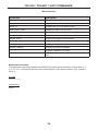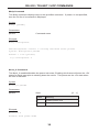
1
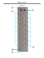
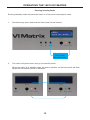
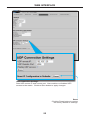
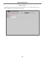
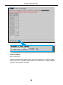
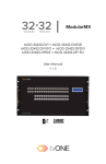
®
16x16 DVI Matrix
EXT-DVI-16416
User Manual
1080P
www.gefen.com
ASKING FOR ASSISTANCE
Technical Support:
Telephone
(818) 772-9100
(800) 545-6900
Fax(818) 772-9120
Technical Support Hours:
8:00 AM to 5:00 PM Monday through Friday, Pacific Time
Write To:
Gefen, LLC
c/o Customer Service
20600 Nordhoff St
Chatsworth, CA 91311
www.gefen.com
[email protected]
Notice
Gefen, LLC reserves the right to make changes in the hardware, packaging and any
accompanying documentation without prior written notice.
16x16 DVI Matrix is a trademark of Gefen, LLC
© 2014 Gefen, LLC. All Rights Reserved
All trademarks are the property of their respective owners.
Rev C18
CONTENTS
1Introduction
2 Operation Notes
3Features
4 Panel Layout
4
Front Panel
5
Back Panel
6 Panel Descriptions
7 IR Remote Control
7
Layout and Description
8
Installing the Battery
8
Setting the IR Channel
9 Connecting the 16x16 DVI Matrix
9
Wiring Diagram
10 Operating the 16x16 DVI Matrix
10
Status Screen
11
Routing Sources
12
Entering Standby mode
13
Exiting Standby mode
14 Routing Sources using the IR Remote Control
15 RS-232 / IP Control
17 RS-232 / Telnet / UDP Commands
17
EDID Management
22
IP / Telnet Configuration
30 Routing
33
Masking
35 Miscellaneous
43 Web Interface
43
View Matrix Status
47
Manage EDID
53
Masking
54
IP Configuration
56
Backup / Restore
57
Power Management
59 Warning Messages
61 Network Cable Wiring Diagram
62 Rack Mount Safety Information
63 Specifications
64Warranty
65Licensing
INTRODUCTION
Congratulations on your purchase of the 16x16 DVI Matrix. Your complete satisfaction is
very important to us.
Gefen
Gefen delivers innovative computer and electronic solutions that harness integration,
extension, distribution and conversion technologies. Gefen’s reliable, plug-and-play
products supplement cross-platform computer systems, professional audio/video
environments and HDTV systems of all sizes with hard-working solutions that are easy to
implement and simple to operate.
The Gefen 16x16 DVI Matrix
Simplify the process of routing multiple DVI sources giving the ability to route sources
without losing quality or resolution. Route 16 sources to 16 digital monitors using the Gefen
16x16 DVI Matrix. The Matrix provides a simple, reliable, and highly effective method of
streamlining any installation using multiple sources and outputs. It takes the hassle out of
multiple wiring schemes. Four methods are available for controlling the Gefen 16x16 DVI
Matrix: Front panel buttons, IR remote, RS-232 interface, or using IP control.
How It Works
The 16x16 DVI Matrix has sixteen DVI inputs and sixteen DVI outputs. Connect your
sixteen computers to the DVI input ports on the Matrix’s input side. Connect the Matrix’s
sixteen DVI outputs to the displays. Connect the power supply to the Matrix and connect
the power cord to an available wall outlet. The connected displays will show video
according to the selection.
NOTE: This device only supports DVI-D.
1
OPERATION NOTES
READ THESE NOTES BEFORE INSTALLING OR
OPERATING THE 16X16 DVI MATRIX
•
The 16x16 DVI Matrix does not support HDCP content.
•
Make sure that a DVI monitor is powered and connected to one of the DVI outputs on
the 16x16 DVI Matrix before applying power. By default, the Local EDID is read from
the connected monitor and is copied to all 16 DVI inputs once the Matrix has been
turned on. If a monitor is not detected by the Matrix at power-on, a default (internal)
EDID of 640x480 will be used. This functionality can be disabled using the Secure
Local EDID function using RS-232, Telnet, UDP, or the built-in Web interface.
•
There is no internal scaling in the 16x16 DVI Matrix. Each monitor attached to the
Matrix must be able to display the resolutions output by the source device(s). For
maximum compatibility it is recommended that only one common resolution be used
by each source device.
•
Advanced EDID features are accessible using RS-232, Telnet, UDP, or the built-in
Web interface.
•
Routing and EDID features can be managed using the built-in IP control features.
•
This matrix supports Dynamic EDID. See pages 17 and 44 for details.
•
The Gefen Syner-G Software Suite is a free downloadable application from Gefen that
provides automatic download and installation of firmware upgrades for this product.
Download the application here: http://www.gefen.com/support/download.jsp
•
The Gefen Matrix Switcher Keyboard Controller is a free downloadable application
from Gefen that allows a computer keyboard to be used to switch between sources.
This application uses the Telnet protocol to control any Gefen switcher or matrix that
uses IP control.
Download the application here: http://www.gefen.com/support/download.jsp
2
FEATURES
Features
•
Supports resolutions up to 1920 x 1200
•
Status LCD (shows routing status)
•
Advanced EDID management provides rapid integration of sources and displays
•
Dynamic EDID support
•
Serial RS-232 interface for remote control via a computer or control automation
devices
•
IP Control (Telnet, UDP, and Web interface)
•
Output masking command
•
IR Remote Control
•
IR Extender
•
Standby mode
•
Supports DDWG standards for DVI
•
Rack-mountable
Package Includes
(1) 16x16 DVI Matrix
(16) 6 ft. DVI cables (M-M)
(1) 6 ft. DB-9 cable
(1) IR Remote control unit
(1) 24V DC power supply
(1) AC power cord
(1) Quick-Start Guide
3
PANEL LAYOUT
1
2
5
3
4
Front Panel
4
PANEL LAYOUT
11
10
6
9
7
8
Back Panel
5
PANEL DESCRIPTIONS
1
Control Buttons
These buttons are used to navigate the functions of the 16x16 DVI Matrix. For complete
details on these controls and how they are used, see pages 10 - 13.
2
Infrared (IR) Receiver
This IR receiver will accept commands from the RMT-16416IR remote control. Line-ofsight between this receiver and the remote controls needs to be preserved for proper
operation.
3
Power LED Indicator
This LED indicator will be active when the included 24V DC power supply is properly
connected to the unit.
4
Cancel Button
This button is used to return the user to the main status screen once a routing change has
been initiated and the user decides to not continue with the change.
5
Main LCD Display
This 2 line 16 character display will display status information and is also used to manage
the display/source routes.
6
DVI Input Ports 1-16
These inputs are used to connect up to 16 DVI-capable sources.
7
10/100 Ethernet Control Interface
This port is used to connect the 16x16 DVI Matrix to a network for IP control. See page 16
for more information.
8
24V DC Power Receptacle
The port will accept power from the included 24V DC power supply.
9
DVI Output Ports 1-16
These outputs are used to connect up to 16 DVI-capable displays.
10 RS-232 Serial Communications Interface
This interface was designed to accept commands from an external control system. This
port will allow switching commands as well as EDID management and configuration
operations. See page 15 for more information.
11 IR Extender Jack
Accepts an optional IR Extender which allows relocation of the IR receiver up to 6 feet
away from the Matrix.
6
IR REMOTE CONTROL
RMT-16416IR Layout and Description
1
2
1
Activity Indicator
This LED will be activated momentarily each time a button is pressed.
2
Display and Source Selection Buttons (1 - 16)
These buttons are used to select which source is routed to a monitor.
NOTE: An Activity Indicator that flashes quickly while holding down
any one of the 16 buttons indicates a low battery. Replace the IR
Remote Control battery as soon as possible.
7
IR REMOTE CONTROL
Installing the Battery
The Remote Control unit ships with two batteries. One battery is required for operation
and the other battery is a spare.
1.
Remove the battery cover on the back of the IR Remote Control unit.
2.
Insert the included battery into the open battery slot. The positive (+) side of the
battery should be facing up.
3.
Replace the battery cover.
Channel 0 (default):
Remote Channel 1:
ON
1
2
Remote Channel 2:
ON
1
Remote Channel 3:
ON
Battery slot
DIP switches
1
2
2
ON
1
2
Setting the IR Channel
The IR channel on the IR Remote Control must match the IR channel used by the DVI
16x16 Matrix. For example, if both DIP switches on the IR Remote Control unit are set to
IR channel 0 (both DIP switches down), then the 16x16 DVI Matrix must also be set to IR
channel 0. See page 37 for information on how to change the IR channel on the DVI 16x16
Matrix.
WARNING: Risk of explosion if battery is replaced by an incorrect
type. Dispose of used batteries according to the instructions.
8
CONNECTING THE 16X16 DVI MATRIX
How to Connect the 16x16 DVI Matrix
1.
Connect up to 16 DVI source devices to the DVI inputs on the rear panel of the
16x16 DVI Matrix using the supplied DVI cables.
2.
Connect up to 16 DVI monitors to the DVI outputs on the rear panel of the 16x16 DVI
Matrix with DVI cables.
3.
Connect the included 24V DC power supply to the power receptacle on the rear panel
of the 16x16 DVI Matrix.
4.
Connect the included AC power cord between the power supply and an available
electrical outlet.
Wiring Diagram for the 16x16 DVI Matrix
CAT-5 CABLE
DVI CABLE
RS-232 CABLE
16x
DVI Sources
Matrix
IP Control
16x
EXT-DVI-16416
DVI Displays
RS-232 Controller
ATTENTION: This product should always be connected to a
grounded electrical socket.
9
OPERATING THE 16X16 DVI MATRIX
Status Screen
The status screen is a 16-character 2-line LCD display. This display shows the current
status of the matrix and is also used to perform routing and other functions. When the unit
is powered on, the following screen is displayed:
EDID LOADING
PLEASE WAIT
After a few moments, the following is displayed in the status screen:
GEFEN
16x16 DVI MATRIX
Displaying Additional Information
Pressing the ◄ button consecutively, will cycle through other screens such as firmware
and boot loader version:
MATRIX FIRMWARE
6.1.2
BOOT LOADER
1.5
GEFEN
16x16 DVI MATRIX
10
OPERATING THE 16X16 DVI MATRIX
Routing Sources
1
Press the Select button to display the routing screen.
> OUTPUT:
INPUT:
01
01
Select button
2
Use the ◄ or ► buttons to select the display that will receive the source signal.
3
Press the Select button to confirm the output selection. Otherwise, press the Cancel
button.
OUTPUT: 01
14
> INPUT:
4
Use the ◄ or ► buttons to select the desired source to be routed to the display,
which was selected in Step 2.
5
Press the Select button to confirm the input selection. Otherwise, press the Cancel
button.
6
Press the Cancel button to return to the Standby screen.
11
OPERATING THE 16X16 DVI MATRIX
Entering Standby Mode
Entering Standby mode will place the matrix in a low power-consumption state.
1.
Simultaneously press and hold the Select and Cancel buttons.
GEFEN
16x16 DVI MATRIX
Press Select
and Cancel
Simultaneously
2.
The matrix will power-down and go into standby mode.
When the matrix is in standby mode, the power indicator on the front-panel will flash
bright red until standby mode is disabled.
12
OPERATING THE 16X16 DVI MATRIX
Exiting Standby Mode
1.
Press and hold any button on the front panel until the front-panel LCD comes on.
GEFEN
16x16 DVI MATRIX
2.
Once the matrix turns on, release the button.
13
OPERATING THE 16X16 DVI MATRIX
Routing Sources using the IR Remote Control
To route sources using the IR Remote Control, select the output first, then the input.
Routing Example: Route Input 12 to Output 3
1.
Select Output 3 by pressing button 3 on the IR Remote Control. The number 03 will
appear next to OUTPUT, in the display:
LED indicates a
button was pressed
Output 3 selected
> OUTPUT:
INPUT:
03
03
2.
The cursor will automatically advance to the input selection.
3.
Select Input 12 by pressing button 12 on the IR Remote Control. The number 12 will
appear next to INPUT, in the display.
4.
Input 12 is now routed to Output 3, as shown on the display.
5.
After the input is selected, the cursor will automatically return to the output selection.
OUTPUT: 03
12
> INPUT:
Input 12 selected
14
RS-232 / IP CONTROL
RS-232 Interface
5 4
3
2 1
DE-9
6 7
8
9
DA-15
RS-232 Controller
Matrix
DCD
1
1
DCD
RXD
2
2
RXD
TXD
3
3
TXD
DTR
4
4
DTR
GND
5
5
DSR
6
6
RTS
7
7
CTS
8
8
CTS
R1
9
9
R1
Only TXD, RXD, and GND are used.
DB-25
GND
DSR
RTS
DC-37
RS232 Settings
Baud rate .......................................................................................................................19200
Data bits ............................................................................................................................... 8
Parity bits ....................................................................................................................... None
Stop bits ................................................................................................................................1
Flow Control ................................................................................................................... None
DD-50
IMPORTANT: When sending RS-232 commands, a carriage return
must be included at the end of the command. A space must be
included between the command and the parameter.
15
RS-232 / IP CONTROL
IP Configuration
The 16x16 DVI Matrix supports IP-based control using Telnet, UDP, or the built-in
Web-based GUI. To set up IP control, the network settings for the 16x16 DVI Matrix
must be configured via RS-232. The default network settings for the matrix are as follows:
IP Address:
Subnet: Gateway:
HTTP Port:
Telnet Port:
192.168.1.72
255.255.255.0
192.168.1.254
80
23
1.
Connect an RS-232 cable from the PC to the 16x16 DVI Matrix. Also make sure that
an Ethernet cable is connected between the matrix and the network.
2.
Launch a terminal emulation program (e.g. HyperTerminal) and use the RS-232
settings listed on page 15.
NOTE: Depending upon the network, all related IP, Telnet, and
UDP settings will need to be assigned. Consult your network
administrator to obtain the proper settings.
3.
Set the IP address for the matrix using the #sipadd command (see page 28
for details).
4.
Set the subnet mask using the #snetmask command (see page 28 for details).
5.
Set the gateway (router) IP address using the #sgateway command
(see page 27 for details).
6.
Set the Telnet listening port using the #set_tcp_term_port command
(see page 25 for details).
7.
Set the HTTP listening port using the #set_http_port command
(see page 24 for details).
8.
Power-cycle the matrix to reboot and complete all IP setting changes.
9.
Type the IP address that was specified in step 3, in a web browser to access
the Web GUI or use the same IP address to Telnet to the matrix.
UDP Configuration
1.
Set the UDP remote IP address for the matrix using the #set_udp_rip command
(see page 26 for details).
2.
Set the UDP listening port for the matrix using the #set_udp_port command (see
page 25 for details).
3.
Set the UDP remote port for the matrix using the #set_udp_rport command (see
page 26 for details).
16
RS-232 / TELNET / UDP COMMANDS
EDID Management
Command
Description
#dynamic_edid
Enables / disables dynamic EDID
#edidbatolo
Read downstream EDID and stores in any Local Input
#ediddetolo
Sets Local EDID to Default EDID
#ediddstoba
Read downstream EDID and stores in EDID Bank
#ediddstolo
Read downstream EDID and stores into a Local EDID
#lock_edid
Secures Local EDID
#prbaedid
Read EDID from an EDID bank and sends to serial port
#prdsedid
Read downstream EDID and sends to serial port
#predidst
Prints EDID details
#prloedid
Read Input Local EDID and sends to serial port
#dynamic_edid Command
The #dynamic_edid command provides the ability to route any downstream EDID to any
input. When enabled, the EDID is copied to all inputs from the last selected active output.
When disabled, the EDID is copied to all inputs from the first active display detected, starting from Output 1.
Syntax:
#dynamic_edid param1
Parameters:
param1Value[0 - 1]
Value
Meaning
0
Disable
1
Enable
Default:
Disabled
17
RS-232 / TELNET / UDP COMMANDS
#edidbatolo Command
The #edidbatolo command reads the downstream EDID and stores it to any local input.
Syntax:
#edidbatolo param1 param2 [param3...param9]
Parameters:
param1
EDID bank
[1 ... 3]
param2
Input
[1 ... 16]
Notes:
If param2 = 0, then the EDID in the specified bank is copied to all 16 inputs.
#ediddetolo Command
The #ediddetolo command stores the Default EDID (640x480) in the specified Local EDID
inputs.
Syntax:
#ediddetolo param1 param2 param3...param9
param1Input[1 ... 16]
Notes:
If param1 = 0, then all 16 DVI inputs will be set to the Default EDID.
18
RS-232 / TELNET / UDP COMMANDS
#ediddstoba Command
The #ededdstoba command reads the downstream EDID and stores it to a
specified EDID bank.
Syntax:
#ediddstoba param1 param2
Parameters:
param1
A downstream monitor
[1 ... 16]
param2
EDID bank offset
[1 ... 3]
#ediddstolo Command
The #ediddstolo command reads the downstream EDID and stores it to a Local EDID input.
Syntax:
#ediddstolo param1 param2 [param3...param9]
Parameters:
param1
A downstream monitor
[1 ... 16]
param2Input list[1 ... 16]
Notes:
If param2 = 0, then the downstream EDID is stored to all 16 DVI inputs.
If more than eight inputs need to be specified in order to receive the downstream EDID,
then the #ediddstolo command must be executed twice.
Example:
#ediddstolo 2 1 2 3 4 5 6 7 8 9 10 11(not permitted!)
Instead, run the function twice:
#ediddstolo 2 1 2 3 4 5 6 7 8
#ediddstolo 2 10 11
19
RS-232 / TELNET / UDP COMMANDS
#lock_edid Command
The #lock_edid command secures the Local EDID and disables the automatic loading of
the downstream EDID after the matrix is powered on. This feature can also be controlled
using the Web Interface (see page 52).
Syntax:
#lock_edid param1
Parameters:
param1Input[0 ... 1]
Value
Meaning
0
Disable
1
Enable
#prbaedid Command
The #prbaedid command reads the EDID file from the specified bank and sends it to the
serial port.
Syntax:
#prbaedid param1
Parameters:
param1
EDID bank
[1 ... 3]
#prdsedid Command
The #prdsedid command reads the downstream EDID and sends it to the serial port.
Syntax:
#prdsedid param1
Parameters:
param1
A downstream monitor
20
[1 ... 16]
RS-232 / TELNET / UDP COMMANDS
#predidst Command
The #predidst command reads the downstream EDID. This command displays a table
containing details relating to the Local EDID and the monitor name.
Syntax:
#predidst
Parameters:
None
#prloedid Command
The #prloedid command reads the local EDID of a specified input and spools it to the serial
port.
Syntax:
#prloedid param1
Parameters:
param1
Input[1 ... 16]
21
RS-232 / TELNET / UDP COMMANDS
IP / Telnet Configuration
Command
Description
#ipconfig
Displays all TCP/IP settings
#resetip
Resets IP configuration to factory settings
#set_http_port
Sets the Web server listening port
#set_tcp_term_pass
Sets the TCP terminal password
#set_tcp_term_port
Sets the Telnet listening port
#set_udp_port
Sets the local UDP listening port
#set_udp_rip
Sets the remote UDP IP address
#set_udp_rport
Sets the remote UDP port
#sgateway
Sets the IP gateway address
#show_tcp_term_pass
Displays the current TCP password for login
#sipadd
Sets the IP address of the matrix
#snetmask
Sets the IP network mask
#use_tcp_term_pass
Enables / disables password prompt for TCP
sessions
#use_udp_access
Enables / disables UDP listening
22
RS-232 / TELNET / UDP COMMANDS
#ipconfig Command
The #ipconfig command displays all TCP/IP settings on the matrix.
Syntax:
#ipconfig
Parameters:
None
Example:
#ipconfig
-------------- TCP/IP settings ------------MAC add
= 00:1C:91:01:01:01
IP add
= 192.168.1.72
Net Mask = 255.255.255.0
Gateway
= 192.168.1.254
Web Server Port = 80
TCP Terminal Server Port = 23
TCP Terminal password at login is set to ON
UDP Server Port = 25665
UDP Remote IP = 110.0.255.255
UDP Remote Port = 26989
UDP Access = Disabled
#resetip Command
The #resetip command resets all TCP/IP settings to factory defaults.
Syntax:
#resetip
Parameters:
None
Notes:
The matrix must be rebooted after executing this command.
23
RS-232 / TELNET / UDP COMMANDS
#set_http_port Command
The #set_http_port command sets the Web server listening port. The default port is 80.
Syntax:
#set_http_port param1
Parameters:
param1
Port[0 ... 65535]
Notes:
The matrix must be rebooted after executing this command.
#set_tcp_term_pass Command
The #set_tcp_term_pass command sets the TCP password. The maximum length of the
password is 20 characters and is case-sensitive. The default password is Admin.
Syntax:
#set_tcp_term_pass param1
Parameters:
param1
Current password
param2
New password
param3
New password (confirm)
Notes:
The matrix must be rebooted after executing this command.
Example:
#set_tcp_term_pass Admin reindeer reindeer
TCP Terminal password updated to: reindeer
24
RS-232 / TELNET / UDP COMMANDS
#set_tcp_term_port Command
The #set_tcp_term_port command sets the Telnet listening port. The default port
value is 23.
Syntax:
#set_tcp_term_port param1
Parameters:
param1
Port[1 ... 65535]
Notes:
The matrix must be rebooted after executing this command.
Example:
#set_tcp_term_port 20
New TCP Terminal port set to: 20
#set_udp_port Command
The #set_udp_port command sets the local UDP listening port. The default port value is 8.
Syntax:
#set_udp_port param1
Parameters:
param1
Port[1 ... 65535]
Notes:
The matrix must be rebooted after executing this command.
Example:
#set_udp_port 10
New UDP listening port set to: 10
25
RS-232 / TELNET / UDP COMMANDS
#set_udp_rip Command
The #set_udp_rip command sets the remote UDP IP address. The default port
value is 8.
Syntax:
#set_udp_rip param1
Parameters:
param1
IP Address
Notes:
The matrix must be rebooted after executing this command.
Example:
#set_udp_rip 192.168.1.20
New remote UDP IP address set to: 192.168.1.20
#set_udp_rport Command
The #set_udp_rport command sets the remote UDP port.
Syntax:
#set_udp_rport param1
Parameters:
param1
Port
Notes:
The matrix must be rebooted after executing this command.
Syntax:
#set_udp_rport 4096
New remote UDP port set to: 4096
26
RS-232 / TELNET / UDP COMMANDS
#sgateway Command
The #sgateway sets the IP gateway (router) address. Dot-decimal notation must be used
when specifying the IP address. The default gateway is 192.168.1.254.
Syntax:
#sgateway param1
Parameters:
param1
IP gateway
Notes:
The matrix must be rebooted after executing this command.
Example:
#sgateway 192.168.1.1
New IP Gateway set to: 192.168.1.1
#show_tcp_term_pass Command
The #show_tcp_term_pass command displays the current TCP password for login
(if required).
Syntax:
#show_tcp_term_pass
Example:
#show_tcp_term_pass
TCP Terminal password: reindeer
27
RS-232 / TELNET / UDP COMMANDS
#sipadd Command
The #sipadd command sets the IP address of the matrix. Dot-decimal notation must be
used when specifying the IP address.
Syntax:
#sipadd param1
Parameters:
param1
IP address
Notes:
The matrix must be rebooted after executing this command.
Example:
#sipadd 192.168.1.239
New IP set to: 192.168.1.239
#snetmask Command
The #snetmask command sets the IP network mask. Dot-decimal notation must be used
when specifying the IP network mask.
Syntax:
#snetmask param1
Parameters:
param1
Network mask
Notes:
The matrix must be rebooted after executing this command.
Example:
#snetmask 255.255.255.0
New IP Mask set to: 255.255.255.0
28
RS-232 / TELNET / UDP COMMANDS
#use_tcp_term_pass Command
The #use_tcp_term_pass command enables / disables the password prompt at the
beginning of a session. The default setting is disabled. This feature can also be enabled or
disabled through the Web GUI (see page 54).
Syntax:
#use_tcp_term_pass param1
Parameters:
param1
State
Value
Meaning
0
Disable password
1
Enable (force) password
[0 ... 1]
Example:
#use_tcp_term_pass 1
TCP Terminal password at login is set to ON
#use_udp_access Command
The #use_udp_access command enables / disables UDP listening.
Syntax:
#use_udp_access param1
Parameters:
param1
State
Value
Meaning
0
Disable password
1
Enable (force) password
Example:
#use_udp_access 1
UDP access is set to ON
29
[0 ... 1]
RS-232 / TELNET / UDP COMMANDS
Routing
Command
Description
#callpreset
Recalls a routing / mask preset
#prpreset
Displays the preset table
#savepreset
Saves the current routing/masking state to a
preset
r
Routes the specified inputs to the specified
outputs
s
Routes the specified input to all outputs
#callpreset Command
The #callpreset command recalls a routing preset. Any masked outputs will also be recalled.
Syntax:
#callpreset param1
Parameters:
param1
Preset[1 ... 16]
#prpreset Command
The #prpreset command displays the preset table.
Syntax:
#prpreset
Parameters:
None
30
RS-232 / TELNET / UDP COMMANDS
Example:
#prpreset
PreSet|Out1| 2 | 3 | 4 | 5 | 6 | 7 | 8 | 9 | 10| 11| 12| 13| 14| 15| 16
------|----|---|---|---|---|---|---|---|---|---|---|---|---|---|---|--1
|M 0 |M 0|M 0|M 0|M 0|M 0|M 0|M 0|M 0|M 0|M 0|M 0|M 0|M 0|M 0|M 0
2
|M 0 |M 0|M 0|M 0|M 0|M 0|M 0|M 0|M 0|M 0|M 0|M 0|M 0|M 0|M 0|M 0
3
|M 0 |M 0|M 0|M 0|M 0|M 0|M 0|M 0|M 0|M 0|M 0|M 0|M 0|M 0|M 0|M 0
4
|M 0 |M 0|M 0|M 0|M 0|M 0|M 0|M 0|M 0|M 0|M 0|M 0|M 0|M 0|M 0|M 0
5
|M 0 |M 0|M 0|M 0|M 0|M 0|M 0|M 0|M 0|M 0|M 0|M 0|M 0|M 0|M 0|M 0
6
|M 0 |M 0|M 0|M 0|M 0|M 0|M 0|M 0|M 0|M 0|M 0|M 0|M 0|M 0|M 0|M 0
7
|M 0 |M 0|M 0|M 0|M 0|M 0|M 0|M 0|M 0|M 0|M 0|M 0|M 0|M 0|M 0|M 0
8
|M 0 |M 0|M 0|M 0|M 0|M 0|M 0|M 0|M 0|M 0|M 0|M 0|M 0|M 0|M 0|M 0
9
|M 0 |M 0|M 0|M 0|M 0|M 0|M 0|M 0|M 0|M 0|M 0|M 0|M 0|M 0|M 0|M 0
10
|M 0 |M 0|M 0|M 0|M 0|M 0|M 0|M 0|M 0|M 0|M 0|M 0|M 0|M 0|M 0|M 0
11
|M 0 |M 0|M 0|M 0|M 0|M 0|M 0|M 0|M 0|M 0|M 0|M 0|M 0|M 0|M 0|M 0
12
|M 0 |M 0|M 0|M 0|M 0|M 0|M 0|M 0|M 0|M 0|M 0|M 0|M 0|M 0|M 0|M 0
13
|M 0 |M 0|M 0|M 0|M 0|M 0|M 0|M 0|M 0|M 0|M 0|M 0|M 0|M 0|M 0|M 0
14
|M 0 |M 0|M 0|M 0|M 0|M 0|M 0|M 0|M 0|M 0|M 0|M 0|M 0|M 0|M 0|M 0
15
|M 0 |M 0|M 0|M 0|M 0|M 0|M 0|M 0|M 0|M 0|M 0|M 0|M 0|M 0|M 0|M 0
16
|M 0 |M 0|M 0|M 0|M 0|M 0|M 0|M 0|M 0|M 0|M 0|M 0|M 0|M 0|M 0|M 0
------|----|---|---|---|---|---|---|---|---|---|---|---|---|---|---|---
#savepreset Command
The #savepreset command saves the current routing state to the specified
preset. Any masked outputs will also be saved as part of the current routing state.
Syntax:
#savepreset param1
Parameters:
param1
Preset[1 ... 16]
31
RS-232 / TELNET / UDP COMMANDS
r Command
The r command routes the specified input to the specified outputs.
Syntax:
r param1 param2[...param17]
Parameters:
param1
Input[1 ... 16]
param2
Outputs[1 ... 16]
Notes:
If param2 = 0, then the specified input is routed to all outputs.
Examples:
r 7 3 4 5 6 10 12
Input 7 is routed to outputs: 3 4 5 6 10 12
r 2 0
All outputs are routed to Input 2
s Command
The s command routes the specified input to all outputs.
Syntax:
s param1
Parameters:
param1
Input[1 ... 16]
Example:
s 1
All outputs are routed to Input 1
32
RS-232 / TELNET / UDP COMMANDS
Masking
Command
Description
#maskout
Masks the selected (video) output(s)
#unmaskout
Unmasks the selected output(s)
#maskout Command
The #maskout command allows blanking of the specified outputs.
Syntax:
#maskout param1 param2
Parameters:
param1
Output[1 ... 16]
param2
State
Value
Meaning
0
Unmask
1
Mask
[0 ... 1]
Notes:
If param1 = 0, then all outputs will be masked.
The current masking state will be lost if power is interrupted or if the masking state is not
saved (see #savepreset on page 31).
33
RS-232 / TELNET / UDP COMMANDS
#unmaskout Command
The #unmaskout command unmasks the specified outputs.
Syntax:
#unmaskout param1...param8
Parameters:
param1
Output[1 ... 16]
Notes:
If param1 = 0, then all outputs will be unmasked.
Examples:
#unmaskout 3 8 10
Activate outputs: 3 8 10
#unmaskout 0
Activate all outputs
34
RS-232 / TELNET / UDP COMMANDS
Miscellaneous
Command
Description
#fadefault
Resets the matrix to factory default routing
#help
Displays all available commands
#lock_fo
Toggles the +5V lock power state
#set_input_name
Specifies a name for an input
#set_ir
Sets the IR channel of the matrix
#set_output_name
Specifies a name for an output
#show_temp
Displays the board temperatures
#show_user_name
Displays the TCP user name
#show_ver_data
Displays the current hardware
#show_voltage
Displays the board voltages
f
Toggles / displays +5V input
m
Displays the current routing status in tabular
form
#fadefault Command
The #fadefault command disables the EDID lock state, sets the default routing state (1-1,
2-2, 3-3, etc.) and resets the input and output names to the default names (e.g. Output 1,
Input 1).
Syntax:
#fadefault
Parameters:
None
35
RS-232 / TELNET / UDP COMMANDS
#help Command
The #help command displays help on the specified command. If param1 is not specified,
then the full list of commands is displayed.
Syntax:
#help [param1]
Parameters:
param1
Command name
Example:
#help #callpreset
Cmd #callpreset: Recall a routing and mask state preset
Syntax: #callpreset param1
Param1 = 1-16 (preset)
e.g: #callpreset 2
#lock_fo Command
The #lock_fo enables/disables the power lock state. Enabling this feature will store the +5V
status for each input prior to shutting down the matrix. This preserves the +5V state when
the unit is restarted.
Syntax:
#lock_fo param1
Parameters:
param1
State
Value
Meaning
0
Disable power lock
1
Enable power lock
Example:
#lock_fo 0
Disable Lock power mode
36
[0 ... 1]
RS-232 / TELNET / UDP COMMANDS
#set_input_name Command
The #set_input_name command provides a name to the selected input. For example,
“Input 1” could be renamed as “Computer 1”. The maximum string length for param2 is
15 characters. Special characters and spaces are not permitted. If required, use the
underscore character (“_”) to separate characters.
Syntax:
#set_input_name param1 param2
Parameters:
param1
Input[1 ... 16]
param2
Name
Example:
#set_input_name 5 computer1
computer1 is assigned to input 5
#set_ir Command
The #set_ir set the IR channel for the matrix. The associated DIP switch settings for the IR
remote control unit are returned. See page 8 for details on setting the IR channel for the IR
remote control.
Syntax:
#set_ir param1
Parameters:
param1
Channel[0 ... 3]
Example:
#set_ir 2
RMT_IR - SW1=0,SW2=1
37
RS-232 / TELNET / UDP COMMANDS
#set_output_name Command
The #set_output_name command provides a name to the selected output. For example,
“Output 1” could be renamed as “HDDisplay”. The maximum string length for param2 is
15 characters. Special characters and spaces are not permitted. If required, use the
underscore character (“_”) to separate characters.
Syntax:
#set_output_name param1 param2
Parameters:
param1
Output[1 ... 16]
param2
Name
Example:
#set_output_name 3 display_3
display_3 is assigned to output 3
#show_temp Command
The #show_temp command displays the board temperatures to the screen.
Syntax:
#show_temp
Parameters:
None
Example:
#show_temp
Temperature near cross point top side is 50
Temperature near cross point bottom side is 44 C degree
Temperature on input board is 43 C degree
38
RS-232 / TELNET / UDP COMMANDS
#show_user_name Command
The #show_user_name command displays the current TCP terminal user name.
Syntax:
#show_user_name
Parameters:
None
Example:
#show_user_name
TCP Terminal login: Administrator
#show_ver_data Command
The #show_ver_data command displays the hardware and firmware version ot the screen.
Syntax:
#show_ver_data
Parameters:
None
Example:
#show_ver_data
Hardware version 2
Firmware Release version 6.1.2
Release date: Jan 21 2013
Release time: 16:38:56
Boot loader version 1.5
39
RS-232 / TELNET / UDP COMMANDS
#show_voltage Command
The #show_voltage command displays board voltages to the screen.
Syntax:
#show_voltage
Parameters:
None
Example:
#show_voltage
Analog voltage 3.3 , measured 3262 mV
Analog voltage 1.8 , measured 1781 mV
Analog voltage 1.2 , measured 1180 mV
40
RS-232 / TELNET / UDP COMMANDS
f Command
The f command enables / disables the +5V on the specified input. Do not precede this
command with the “#” symbol.
WARNING: Use caution when applying power to inputs. If the
source device supplies +5V on the input, then enabling the +5V
may cause damage to the source and/or the 16x16 DVI Matrix.
Syntax:
f param1 param2
Parameters:
param1
Input[1 ... 16]
param2
State
Value
Meaning
0
Disable
1
Enable
Notes:
If param1 = 0, then all inputs will be affected.
Examples:
f 15 1
Enable F0 15
f 0 1
Enable All FO
41
[0 ... 1]
RS-232 / TELNET / UDP COMMANDS
m Command
The m command displays the routing status in tabular form. Do not precede this command
with the “#” symbol.
Syntax:
m
Parameters:
None
Example:
m
Output
|
Input
|
HPD
| Status
----------------|----------------|-------|-------Output_1|
Input_1|
LOW | ACTIVE
Output_2|
Input_1|
LOW | ACTIVE
Output_3|
Input_1|
LOW | ACTIVE
Output_4|
Input_1|
LOW | ACTIVE
Output_5|
Input_1|
LOW | ACTIVE
Output_6|
Input_1|
LOW | ACTIVE
Output_7|
Input_1|
LOW | ACTIVE
Output_8|
Input_1|
LOW | ACTIVE
Output_9|
Input_1|
LOW | ACTIVE
Output_10|
Input_1|
LOW | ACTIVE
Output_11|
Input_1|
LOW | ACTIVE
Output_12|
Input_1|
LOW | ACTIVE
Output_13|
Input_1|
LOW | ACTIVE
Output_14|
Input_1|
LOW | ACTIVE
Output_15|
Input_1|
LOW | ACTIVE
Output_16|
Input_1|
LOW | ACTIVE
----------------|----------------|-------|-------GEFEN PRO
Dynamic EDID mode
RMT_IR - SW1=0,SW2=0
42
WEB INTERFACE
View Matrix Status
Matrix Status
Displays the current routing status of each input and output on the matrix.
Refresh
Click to refresh the Matrix
Status screen
Auto Refresh
Check this box to enable Auto Refresh.
The Auto Refresh function automatically
refreshes the interface every 10 seconds.
43
WEB INTERFACE
Dynamic EDID Mode
Routes any downstream EDID to any input. See #dynamic_edid on page 17
for details on this feature. Options: On, Off. Click the Update Dynamic EDID
State button after selecting either On or Off.
Switch Outputs
Used to route the specified input to the selected output(s). To route a source,
place a check mark next to each Output. Next, click the radio button next to
the desired Input. Press the Switch button to apply the routing change.
44
WEB INTERFACE
Presets
Provides saving and recalling
of routing states.
Pull-down list
Recall Preset
Click the down-arrow on the pull-down list to select
the routing state (1-16) to recall. Click the Recall
Preset button to recall the preset.
Save Preset
Click the down-arrow on the pull-down list to
select the preset location (1-16). Click the Save
Preset button to save the preset.
45
WEB INTERFACE
Rename I/O
Provides custom naming
of each input and output on
the matrix.
Pull-down list
Input
Select the DVI input to rename from the pull-down list. Type the name of
the input in the Input Name field. Click the Save Input Name button to save
changes. See page 37 for naming restrictions.
Output
Select the DVI output to rename from the pull-down list. Type the
name of the output in the Output Name field. Click the Save Output
Name button to save changes. See page 38 for naming restrictions.
46
WEB INTERFACE
Manage EDID
EDID Status
Displays the current EDID status for each input on the matrix and
indicates the current Lock State (page 20).
Refresh
Click to refresh
the Matrix Status
screen
Auto Refresh
Check this box to enable Auto Refresh.
Auto Refresh will automatically update
the screen every 10 seconds.
47
WEB INTERFACE
Set Input to Default EDID
Set Input to Default EDID
Press this button from the Manage EDID screen to access this
menu system.
Set Default EDID
Place a check mark next to the input(s) that should be set to the default EDID.
Click the Set Default EDID button to apply the default EDID to the selected
inputs.
48
WEB INTERFACE
Upload EDID
Upload EDID
Press this button from the Manage EDID screen to
access this menu system.
Load EDID file
Place a check mark next to the input(s) that will receive the EDID data from the
file. The EDID file must be in .bin format. Click the Browse button to locate the
EDID on the computer. Click the Load EDID file button to upload the EDID file
to the matrix.
49
WEB INTERFACE
Download EDID
Download EDID
Press this button from the Manage EDID screen to
access this menu system.
Download EDID File to PC
Select the radio button next to the output, containing the EDID to be
downloaded. Click the Download EDID File to PC button to confirm the
change. The downloaded EDID file will be in .bin format.
50
WEB INTERFACE
Copy EDID
Copy EDID
Press this button from the Manage EDID
screen to access this menu system.
Select Source to Copy from / Select Input(s) to Copy to
Click the radio button next to the input or output containing the EDID to copy.
Note that only a single input or output can be selected at a time. Place a check
mark next to the input(s) where the EDID will be copied. Click the Set EDID
button to confirm the operation.
51
WEB INTERFACE
EDID Lock State
EDID Lock State
Press this button from the Manage EDID
screen to access this menu system.
Update EDID Lock State
Secures the Local EDID and disables the automatic loading
of the downstream EDID after the Matrix is powered on.
Select the radio button next to the Off or On option then click the
Update EDID Lock State button to apply the change.
The EDID Lock State has no effect when the Dynamic EDID
function is activated.
52
WEB INTERFACE
Masking
Matrix Mask Status / Change
Displays the current masking status for each output.
Mask
Click the Mask button to mask the selected output. If the output is already
masked then the button will read “Active” (enabled). Click the (“Active”) button
again to toggle the masking state to “Mask” (disabled).
53
WEB INTERFACE
IP Configuration
IP Settings
Assigns IP address, subnet, gateway, HTTP listening port, and Telnet port.
Note that the MAC address can not be changed. Click the Save button to
apply changes. The matrix must be rebooted for the changes to take effect.
Telnet Login Settings
Sets / forces the password for Telnet sessions to the matrix. Click the
Save button to apply changes.
54
WEB INTERFACE
UDP Connection Settings
Sets UDP remote IP and remote port. Also enables or disables UDP
access to the matrix. Click the Save button to apply changes.
Reset
Click the Reset button to restore
the factory-default IP settings.
55
WEB INTERFACE
Backup / Restore
The Backup / Restore feature for the 16x16 DVI Matrix is not currently implemented and
will be available in a future release of the firmware.
56
WEB INTERFACE
Power Management
Power Status
Enabling this feature will store the +5V status for that input prior to shutting down
the matrix. This preserves the +5V state when the unit is restarted.
Power State
The current
power state is
listed under
the column
titled “5 Volt”.
Click these
buttons to
toggle the
input power
state.
Refresh
Click to refresh
the Power
Status screen
Auto
Refresh
Check
this box to
automatically
update the
screen every
10 seconds.
Save Changes
Click to save the
power lock status.
57
WEB INTERFACE
Power Lock State
In the case of an accidental power loss to the matrix, the +5V state for each input
can be preserved.
Set the specified Power Status buttons (see previous page) and click the radio
button next to ON. Click the Update Power Lock State button to apply changes.
By default, this option is set to Off.
58
WARNING MESSAGES
Fan Failure
The 16x16 DVI Matrix uses an internal fan to maintain a stable operating temperature in
various environments. In the case that the fan fails to start, an alert will appear on the
LCM:
FAN FAILURE!
If the 16x16 Matrix is connected to a PC using a terminal program, the following message
will appear on the display:
Fan failure !!!
This message will continue to be displayed at regular intervals until the fan is functioning.
Although the DVI 16x16 Matrix is still functional, it is recommended that Gefen Technical
Support be notified of the issue. See Asking for Assistance at the beginning of this
manual.
System Failure
In the case of a critical malfunction, the following warning message will be displayed on the
LCM:
SYSTEM FAILURE!
If the 16x16 Matrix is connected to a PC using a terminal program, the following message
will appear on the display:
System failure !!!
The Matrix should be powered-down immediately and contact Gefen Technical Support.
See Asking for Assistance at the beginning of this manual.
59
WARNING MESSAGES
Critical Malfunctions
Temperature Failure
If the measured system temperature exceeds 85° C, the following message will be
displayed on the LCM:
SYSTEM FAILURE!
Power Failure
If the power reading exceeds the tolerance rating (greater than 120% or less than 80%),
the following message will be displayed on the LCM:
SYSTEM FAILURE!
In both cases, the Matrix will stop working and should be powered-down immediately
and contact Gefen Technical Support under the Asking for Assistance section, at the
beginning of this manual.
60
NETWORK CABLE WIRING DIAGRAM
Gefen recommends the TIA/EIA-568-B wiring option. Please adhere to the table
below when field-terminating the cable for use with Gefen products.
Pin
Color
1
Orange / White
2
Orange
3
Green / White
4
Blue
5
Blue / White
6
Green
7
Brown / White
8
Brown
Cabling comes in stranded and solid core types. Gefen recommends using solid
core cabling.
It is recommended to use one continuous run from one end to the other.
Connecting through a patch is not recommended.
61
RACK MOUNT SAFETY INFORMATION
a. Maximum recommended ambient temperature: 45 ˚C (104 ˚F).
b. Increase the air flow as needed to maintain the recommended
temperature inside the rack.
c. Do not exceed maximum weight loads for the rack. Install heavier
equipment in the lower part of the rack to maintain stability.
d. Connect a bonding wire between an approved safety ground and the
grounding screw on the chassis.
62
SPECIFICATIONS
Maximum Pixel Clock ................................................................................................165 MHz
Input Video Signal ................................................................................................1.2 Volts p-p
Video Input Connectors................................................ (16) DVI-I 29-pin, female (digital only)
Video output Connectors.............................................. (16) DVI-I 29-pin, female (digital only)
IR Extender................................................................................................3.5 mm mini-stereo
RS-232 Interface....................................................................................... DB-9 serial, female
Ethernet (IP control) port.............................................................................RJ-45 (100BaseT)
Power Supply...............................................................................................................24V DC
Power Consumption ........................................................................................60 Watts (max.)
Operating Temperature................................................................+32 to +104 ˚F (0 to +45 ˚C)
Storage Temperature...................................................................-4 to +140 ˚F (-20 to +60 ˚C)
Relative Humidity......................................................................20% ~ 90% (no condensation)
Dimensions (W x H x D) ................................17.25’’ x 3.5” x 12” (438mm x 89mm x 305mm)
Rack-mountable ................................................................ 2U rack space, rack ears included
Shipping Weight ............................................................................................ 30 lbs. (13.6 kg)
63
WARRANTY
Gefen warrants the equipment it manufactures to be free from defects in material and
workmanship.
If equipment fails because of such defects and Gefen is notified within two (2) years from
the date of shipment, Gefen will, at its option, repair or replace the equipment, provided
that the equipment has not been subjected to mechanical, electrical, or other abuse or
modifications. Equipment that fails under conditions other than those covered will be
repaired at the current price of parts and labor in effect at the time of repair. Such repairs
are warranted for ninety (90) days from the day of reshipment to the Buyer.
This warranty is in lieu of all other warranties expressed or implied, including without
limitation, any implied warranty or merchantability or fitness for any particular purpose, all of
which are expressly disclaimed.
1.
Proof of sale may be required in order to claim warranty.
2.
Customers outside the US are responsible for shipping charges to and from Gefen.
3.
Copper cables are limited to a 30 day warranty and cables must be in their original
condition.
The information in this manual has been carefully checked and is believed to be accurate.
However, Gefen assumes no responsibility for any inaccuracies that may be contained
in this manual. In no event will Gefen be liable for direct, indirect, special, incidental, or
consequential damages resulting from any defect or omission in this manual, even if
advised of the possibility of such damages. The technical information contained herein
regarding the features and specifications is subject to change without notice.
For the latest warranty coverage information, refer to the Warranty and Return Policy under
the Support section of the Gefen Web site at www.gefen.com.
PRODUCT REGISTRATION
Please register your product online by visiting the Register Product page under the
Support section of the Gefen Web site.
64
LICENSING
lwIP is licenced under the BSD licence:
Copyright (c) 2001-2004 Swedish Institute of Computer Science.
All rights reserved.
Redistribution and use in source and binary forms, with or without modification,
are permitted provided that the following conditions are met:
1.
Redistributions of source code must retain the above copyright notice, this list of
conditions and the following disclaimer.
2.
Redistributions in binary form must reproduce the above copyright notice, this list of
conditions and the following disclaimer in the documentation and/or other materials
provided with the distribution.
3.
The name of the author may not be used to endorse or promote products derived from
this software without specific prior written permission.
THIS SOFTWARE IS PROVIDED BY THE AUTHOR ``AS IS’’ AND ANY EXPRESS
OR IMPLIED WARRANTIES, INCLUDING, BUT NOT LIMITED TO, THE IMPLIED
WARRANTIES OF MERCHANTABILITY AND FITNESS FOR A PARTICULAR PURPOSE
ARE DISCLAIMED. IN NO EVENT SHALL THE AUTHOR BE LIABLE FOR ANY DIRECT,
INDIRECT, INCIDENTAL, SPECIAL,
EXEMPLARY, OR CONSEQUENTIAL DAMAGES (INCLUDING, BUT NOT LIMITED TO,
PROCUREMENT OF SUBSTITUTE GOODS OR SERVICES; LOSS OF USE, DATA, OR
PROFITS; OR BUSINESS INTERRUPTION) HOWEVER CAUSED AND ON ANY THEORY
OF LIABILITY, WHETHER IN
CONTRACT, STRICT LIABILITY, OR TORT (INCLUDING NEGLIGENCE OR
OTHERWISE) ARISING IN ANY WAY OUT OF THE USE OF THIS SOFTWARE, EVEN IF
ADVISED OF THE POSSIBILITY OF SUCH DAMAGE.
65
Rev C18
20600 Nordhoff St., Chatsworth CA 91311
1-800-545-6900
818-772-9100
www.gefen.com
Pb
This product uses UL or CE listed power supplies.
fax: 818-772-9120
[email protected]