1
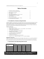
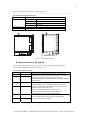
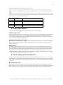
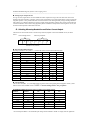
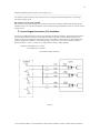
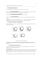
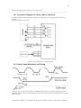
User Manual
For
DCM8028 and DCM8055
High Performance Microstepping Driver
Attention: Please read this manual carefully before using driver!
Haydon Switch & Instrument, Inc. (HSI)
www.hsi-inc.com
203-756-7441 USA
Haydon Linear Motors (HLM)
www.hlm.com.cn
86-519-5113312 5113316 China
Haydon Motion Europe (HME)
www.haydoneurope.com
33-(0) 2 40 92 87 51
The content of this manual has been carefully prepared and is believed to be accurate, but no responsibility is assumed
for inaccuracies.
Haydon does not assume any liability arising out of the application or use of any product or circuit described herein;
neither does it convey any license under the patent rights of others. All third party liabilities are the responsibility of
the customer. Haydon reserves the right to make changes without further notice to any products herein to improve
reliability, performance, function or design.
All Rights Reserved
8-08
2
DCM8055/DCM8028 High Performance Microstepping Driver
_____________________________________________________________________________________________
Table of Contents
1.
2.
3.
4.
5.
6.
7.
8.
9.
10.
11.
Introduction, Features and Applications ·································································2
Specifications and Operating Environment ····························································2
Driver Connectors P1 and P2 ·················································································3
Power Supply ········································································································.4
Driver Voltage and Current ····················································································4
Selecting Microstep Resolution and Driver Current ··············································5
Control Signal Connector (P1) Interface ································································6
Protection Features ·································································································8
Driver Connection to Motors ················································································ 8
Connection Diagram for Driver, Motor, Controller ··············································11
Control signal waveform and timing ·····································································11
1. Introduction, Features and Applications
DCM8055/DCM8028 is a high performance microstepping driver based on the most advanced technology in the world
today. It is suitable for driving 2-phase hybrid step motors (current 5.5A/2.8A). By using advanced bipolar constantcurrent chopping technique, it can output more speed and power from the same motor, compared with traditional
technologies such as L/R drivers. Its current control technology allows coil currents to be accurately controlled, with
much less current ripple and motor heating than other drivers on the market.
Features of this driver
•
High performance, low cost
•
Supply voltage up to +80VDC*, current to 5.5A for DCM8055; 2.8A for DCM8028.
•
Inaudible 20khz chopping frequency
•
TTL compatible and optically isolated input signals
•
Automatic idle-current reduction
•
Mixed-decay current control for less motor heating
•
14 selectable resolutions in decimal and binary
•
Microstep resolutions up to 51,200 steps/rev
•
Suitable for 4,6,8 lead motors
•
Over-current, over-voltage and short-circuit protection
•
Small size (115 x 97 x 48mm for DCM8055, 115 x 97 x 31mm for DCM8028)
Applications of this driver
Suitable for a wide range of stepping motors such as low voltage versions of sizes 11, 14, 17, 23 and 34, and usable for
various kinds of machines, such as X-Y tables, labeling machines, laser cutters, engraving machines, and pick-place
devices, particularly useful in applications with low noise, low vibration, high speed and high precision requirements.
2. Specifications and Operating Environment
Electric Specifications (Tj = 25℃)
DCM8055/DCM8028
Parameters
Min
Typical
Max
Remark
RMS Output Current
2.0A,/1.0A
by user
5.5A,/2.8A
By DIP switch
Supply voltage (DC)
+20V
+68V
+80V *
Logic signal current
10mA
12mA
18mA
Pulse input frequency
0
By user
Isolation resistance
500MΩ
500Khz
NEVER connect power and ground in the wrong polarity, it will damage the driver.
NEVER connect or disconnect the motor leads with power on to the driver.
* For the European Market – the maximum input voltage must be limited to 70VDC to comply with CE regulations.
3
DCM8055/DCM8028 High Performance Microstepping Driver
_____________________________________________________________________________________________
Operating Environment and Parameters
Cooling
Environment
Natural cooling or forced convection
Space
Avoid dust, oil, frost and corrosive gas
Temperature
0°-
Humidity
40 - 90%RH
5.9m/s2Max
Vibration
Storge Temp.
50℃
-20℃ -
Weight
+65℃
About 0.44kg/DCM8055; 0.33kg/DCM8028
DCM8055 Front View
DCM8028 Front View
Figure 1: Mechanical Dimensions
3. Driver Connectors, P1 and P2
The following is a brief description of the two connectors of the driver. More detailed descriptions
of the pins and related issues are presented in section 4, 6, 8, 9.
Control Signal Connector P1-pins
Pin No.
1
2
Signal
Pul﹢(+5V)
Pul﹣(pulse)
3
Dir﹢(+5V)
4
Dir﹣(Dir)
5
Ena+(+5V)
6
Ena- (Ena)
Functions
Pulse signal: in single pulse(pulse/direction) mode, this input
represents pulse signal, effective for each upward – rising edge; in
double pulse mode (pulse/pulse) this input represents
clockwise(CW)pulse. For reliable response, pulse width should be
longer than 3υs.
Direction signal: in single-pulse mode, this signal has
low/high voltage levels, representing two directions of motor
rotation; in double-pulse mode (set by inside jumper JMPI), this
signal is counter-clock (CCW) pulse,
effective on each rising edge. For reliable motion
response, direction signal should be sent to driver 2υs
before the first pulse of a motion direction reversal.
Enable signal: this signal is used for enable/disable, high
level for enabling driver and low level for disabling driver.
Usually left unconnected(enabled).
* For the European Market – the maximum input voltage must be limited to 70VDC to comply with CE regulations.
4
DCM8055/DCM8028 High Performance Microstepping Driver
_____________________________________________________________________________________________
Remark 1: Pul/dir is the default mode, under-cover jumper JMP1 can be used to switch toCW/CCW double-pulse
mode.
Remark 2: Please note motion direction is also related to motor-driver wiring match. Exchanging the connection of
two wires for a coil to the driver will reverse motion direction. (for example, reconnecting motor A+ to driver A- and
motor A- to driver A+ will invert motion direction).
Power connector P2 pins
Pin No.
Signal
Functions
1
Gnd
DC power ground
2
+V
DC power supply, +20VDC to +80VDC*, Including
3, 4
Phase A
Motor coil A (leads A+ and A-)
5, 6
Phase B
Motor coil B (leads B+ and B-)
voltage fluctuation and EMF voltage.
4. Power supply Selection
It is important to choose appropriate power supply to make the driver operate properly.
Maximum Voltage Input:
The power Mosfet inside the driver can actually operate within +20V to +80VDC*, including power input fluctuation
and back EMF voltage generated by motor coils during motor shaft deceleration. Higher voltage will damage the
driver. Therefore, it is suggested to use power supplies with theoretical output voltage of no more than +75V, leaving
room for power line fluctuation and Back EMF.
Regulated or Unregulated power supply:
Both regulated and unregulated power supplies can be used to supply DC power to the driver. However, unregulated
power supplies are preferred due to their ability to withstand current surge. If a regulated power supply is used, it
should be a linear type.
Multiple drivers:
It is possible to have multiple drivers share one power supply to reduce cost, provided that the supply has enough
capacity. DO NOT dazy-chain the power supply input pins of the drivers(connect them to power supply separately) to
avoid cross interference. Higher supply voltage will allow higher motor speed to be achieved, at the price of more
noise and heating. If the motion speed requirement is low, it’s better to use lower supply voltage to improve noise,
heating and reliability. NEVER connect power and ground in the wrong polarity, it will damage the driver. NEVER
connect or disconnect the motor leads with power on to the driver.
5. Driver Voltage and Current Selection
This driver can operate small-medium size step motors (such as low voltage versions of sizes 11, 14, 17, 23 and 34)
made by Haydon or other motor manufactures from around the world. To achieve good driving results, it is important
to select supply voltage and output current properly. Generally, supply voltage determines the high speed performance
of the motor,
● Selecting Supply Voltage:
Higher supply voltage can increase motor torque at higher speeds, thus helpful for avoiding losing steps. However,
higher voltage may cause more motor vibration at lower speed, and it may also cause over-voltage protection and even
driver damage. Therefore, it is suggested to choose only sufficiently high supply voltage for intended applications.
* For the European Market – the maximum input voltage must be limited to 70VDC to comply with CE regulations.
5
DCM8055/DCM8028 High Performance Microstepping Driver
_____________________________________________________________________________________________
● Setting Proper Output Current
For a given motor, higher driver current will make the motor output more torque, but at the same time causes more
heating in the motor and driver. Therefore, output current is generally set to be such that the motor will not overheat for
long time operation. Since parallel and serial connections of motor coils will significantly change resulting inductance
and resistance, it is therefore important to set driver output current depending on motor phase current, motor leads and
connection methods. Phase current rating supplied by motor manufacturer is important to selecting driver current, but
the selection also depends on leads and connection:
6. Selecting Microstep Resolution and Driver Current Output
This driver uses an 8-bit DIP switch to set microstep resolution, dynamic current and standstill current, as shown
below:
Current during motion
Microstep resolution
1
2
3
4
5
6
7
8
Standstill Current (half/full)
● Microstep Resolution Selection
Microstep resolution is set by SW5, 6, 7, 8 of the DIP switch as shown in the following table:
Microstep
Step/rev.(for 1.8°motor)
SW6
SW7
SW8
on
on
on
on
on
off
on
on
1600
on
on
off
on
16
3200
on
off
off
on
32
6400
on
on
on
off
64
12800
on
off
on
off
128
25600
on
on
off
off
256
51200
on
off
off
off
5
1000
off
on
on
on
10
2000
off
off
on
on
25
5000
off
on
off
on
2
400
4
800
8
SW5
50
10000
off
off
off
on
125
25000
off
on
on
off
250
50000
off
off
on
off
● Current Setting
The first three bits (SW1, 2, 3) of the DIP switch are used to set the current during motion (dynamic current ), while
SW4 is used to select standstill current. NOTE: Current settings below are per phase.
DCM8028/DCM8055 DIP Switch settings for RMS current during motion:
Current for
DCM8028
1.0A
Current for
DCM8055
2.0A
1.3A
2.5A
SW1
SW2
SW3
on
off
on
on
on
on
1.5A
3.0A
on
off
on
1.8A
3.5A
off
off
2.0A
4.0A
on
2.3A
4.5A
on
off
on
off
2.5A
5.0A
2.8A
5.5A
on
off
on
off
off
off
off
off
* For the European Market – the maximum input voltage must be limited to 70VDC to comply with CE regulations.
6
DCM8055/DCM8028 High Performance Microstepping Driver
_____________________________________________________________________________________________
Note that due to motor inductance the actual current in the coil may be smaller than the dynamic current settings,
particularly at higher speeds.
DIP setting for current during standstill:
SW4 is used for this purpose, the half current setting will reduce motor heating at standstill. OFF meaning that the
standstill current is set to be half of the dynamic current and ON meaning that standstill current is set to be the same as
dynamic current.
7. Control Signal Connector (P1) Interface
This driver uses differential inputs to increase noise immunity and interface flexibility. Single-ended control signals
from the indexer/controller can also be accepted by this interface. The input circuit has built-in high-speed opto coupler, and can accept signals in the format of line driver, open-collector, or PNP output. Line driver (differential)
signals are suggested for reliability. In the following figures, connections to open-collector and PNP signals are
illustrated and VCC = 5VDC. For other VCC voltages limit the current to 18mA maximum.
Examples: R=560ohms if VCC=12VDC
R=1.5Kohms if VCC=24VDC
Open-collector signal (common +)
Figure 2
* For the European Market – the maximum input voltage must be limited to 70VDC to comply with CE regulations.
7
DCM8055/DCM8028 High Performance Microstepping Driver
_____________________________________________________________________________________________
Figure 3: Signal Interface
* For the European Market – the maximum input voltage must be limited to 70VDC to comply with CE regulations.
8
DCM8055/DCM8028 High Performance Microstepping Driver
_____________________________________________________________________________________________
8. Protection Functions
To improve reliability, the driver incorporates a number of built-in protections features.
a. Over-voltage protection
When power supply voltage exceeds +80VDC*, protection will be activated and power indicator LED will turn red.
When power supply voltage is lower than +20VDC, the driver will not work properly.
b. Coil-ground Short Circuit Protection
Protection will be activated in case of short circuit between motor coil and ground.
c. Over-current Protection
Protection will be activated in case of excessive current (such as a short circuit) which may otherwise damage the
driver.
Attention: since there is no protection against power leads (﹢, ﹣) reversal, it is critical to make sure that power
supply leads are correctly connected to driver. Otherwise, the driver will be damaged instantly.
9. Driver Connection to Step Motors
DCM8055/DCM8028 driver can drive 4, 6, 8 lead hybrid step motors. The following diagrams illustrate connection to
various kinds of motor leads:
Figure 4: Driver Connection to Step Motor
Note that when two coils are parallelly connected, coil inductance is reduced by half and motor speed can be
significantly increased. Serial connection will lead to increased inductance and thus the motor can be run well only at
lower speeds.
9.1 Connecting to 8-Lead Motors
8 lead motors offer a high degree of flexibility to the system designer in that they may be connected in series or
parallel, thus satisfying a wide range of applications.
Series Connection
A series motor configuration would typically be used in applications where a higher torque at lower speeds is required.
Because this configuration has the most inductance, the performance will start to degrade at higher speeds. Divide the
motor's unipolar (peak) current rating by 1.4 for the RMS current, or the motor's bipolar current rating is the RMS
current.
* For the European Market – the maximum input voltage must be limited to 70VDC to comply with CE regulations.
9
DCM8055/DCM8028 High Performance Microstepping Driver
_____________________________________________________________________________________________
Figure 5: 8 Lead Motor Series Connections
Parallel Connection
An 8 lead motor in a parallel configuration, because of the lower inductance, will have higher torque at higher speeds.
Multiply the motor's unipolar (peak) current rating by 1.4 for the RMS current, or the motor's bipolar current rating is
the RMS current.
Figure 6: 8 Lead Motor Parallel Connections
9.2 Connection to 6-Lead Motors
Like 8 lead stepping motors, 6 lead motors have two configurations available for high speed or high torque operation.
The higher speed configuration, or half coil, is so described because it uses one half of the motor’s inductor windings.
The higher torque configuration, or full coil, use the full windings of the phases.
Half Coil Configuration
As previously stated, the half coil configuration uses 50% of the motor phase windings, hence, lower torque output.
Like the parallel connection of 8 lead motor, the torque output will be greater at higher speeds due to lower inductance.
This configuration is also referred to as half copper. In setting the driver output current use the motor's specified per
phase (or unipolar) current rating as the RMS current.
* For the European Market – the maximum input voltage must be limited to 70VDC to comply with CE regulations.
10
DCM8055/DCM8028 High Performance Microstepping Driver
_____________________________________________________________________________________________
Figure 7: 6 Lead Half Coil (Higher Speed) Motor Connections
Full Coil Configuration
The full coil configuration on a six lead motor should be used in applications where higher torque at lower speeds is
desired. This configuration is also referred to as full copper. Divide the motor's specified per phase (or unipolar) current
rating by 1.4 for the RMS current.
Figure 8: 6 Lead Full Coil (Higher Torque) Motor
9.3 Connection to 4-Lead Motors
4 lead motors are the least flexible but easiest to wire. Speed and torque will depend on winding inductance. In setting
the driver output current, use the motors specified per phase current rating as the RMS current.
Figure 9: 4 Lead Motor Connections
* For the European Market – the maximum input voltage must be limited to 70VDC to comply with CE regulations.
11
DCM8055/DCM8028 High Performance Microstepping Driver
_____________________________________________________________________________________________
10. Connection Diagram for Driver, Motor, Controller
A complete stepping system should include stepping motor, stepping driver, power supply and controller (pulse
generator).
A typical connection is shown below:
Figure 10: Driver connection in a stepping system
11. Control signal Waveform and Timing
This driver can accept pulse control signals up to 500KHz. Before a direction reversal, direction signal needs to be
established at least 3 υs before the first pulse of the next pulse train. Please examine time diagrams of the three control
signals as follows.
* For the European Market – the maximum input voltage must be limited to 70VDC to comply with CE regulations.