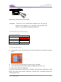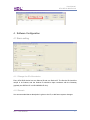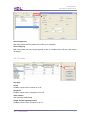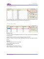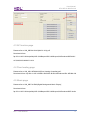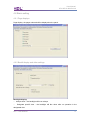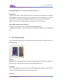
1
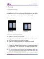
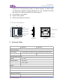
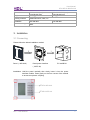
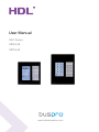
User Manual DLP Series MPL8.48 MPL8.46 www.hdlautomation.com User Manual HDL-MPL8.48/MPL8.46 Document updates: Version Date V1.0 2015.01.20 DLP – User Manual Description Finish new document User Manual HDL-MPL8.48/MPL8.46 INDEX 1. 2. 3. 4. 5. 6. 7. Overview....................................................................................................................................1 1.1 General Information.......................................................................................................... 1 1.1.1 Description.............................................................................................................. 1 1.1.3 Serial Numbers.......................................................................................................1 1.2 Description Of Functions..................................................................................................1 1.3 Device Description............................................................................................................ 2 Technical Data.......................................................................................................................... 2 Installation................................................................................................................................. 3 3.1 Attachment and mounting .............................................................................................. 3 3.2 HDL BUS Pro Description................................................................................................4 3.3 Commissioning.................................................................................................................. 4 Software Configuration............................................................................................................5 4.1 Basic settings..................................................................................................................... 5 4.1.1 Changing the device ID.........................................................................................5 4.1.2 Remark.................................................................................................................... 5 4.1.3 LED intensity...........................................................................................................6 4.2 Key assignation................................................................................................................. 6 4.2.1 Remarks.................................................................................................................. 6 4.2.2 Mode........................................................................................................................ 7 4.2.3 Functions................................................................................................................. 8 4.2.4 Key combinations...................................................................................................9 4.2.5 Uploading an Icon................................................................................................10 4.2.6 Mutual exclusion.................................................................................................. 10 4.2.7 Button merging ................................................................................................... 11 4.2.8 Setting the button functions................................................................................11 4.2.9 IR and other functions.........................................................................................12 4.2.10 Test the button functions.................................................................................. 12 4.3 AC function page.............................................................................................................13 4.4 Floor heating page.......................................................................................................... 13 4.5 Music page....................................................................................................................... 13 4.6 Basic setting.....................................................................................................................13 4.6.1 Page displays....................................................................................................... 13 4.6.2 Backlit display and other settings..................................................................... 14 DLP Setting Page.................................................................................................................. 15 FAQ.......................................................................................................................................... 16 NOTES.....................................................................................................................................19 DLP – User Manual User Manual HDL-MPL8.48/MPL8.46 1. Overview 1.1 General Information 1.1.1 Description The multi-functional LCD panel is a new generation of wall mounted switch, with a total of 8 metal buttons each with a configurable LED. Both the plate and frame can be customized with different materials and colors to perfectly match your lifestyle. 1.1.3 Serial Numbers HDL-MPL8.46 US standard HDL-MPL8.48 EU standard 1.2 Function Qualities Description Adjustable LCD Backlight and LED Indicators. Multiple pages- A specified page for Floor Heating, HVAC, and Music control is available. Each of the keys can have a user designed icon installed. Single button combinations and double button combinations are available. The mutual exclusion of buttons is available. Multi Key Mode: Invalid, Single on-off, single on, single off, Combination on-off, combination on, combination off, double click/single on-off, double click/combination on-off, momentary, clock, short/long press, short press/long momentary press, hyperlink. Multi Key control Modes: Scene, Sequence, timer switch, universal switch, single channel on-off, broadcast scene, broadcast channel, curtain, GPRS Control, Panel Control, alarm control, music play, General control. The following functions are included: IR Receiver, Lock, Turn on/off AC, Cooling & DLP – User Manual 1 User Manual HDL-MPL8.48/MPL8.46 heating for AC. Auto temperature setting, Fan Speed regulation, AC Mode setting, AC Temperature regulation, backlight adjustment, AC Lock, Backlight and status light setting, floor heating temperature and mode setting etc. Communication : HDL Buspro Support online upgrade. Working with panel power interface. 1.3 Device Description 10.5 86 LCD Button indicator Signal interface Control button 86 Fastener Button for page shifting Split gap Front view Side view Back view 2. Technical Data MPL8.48 MR0810.432 Electric Parameter : Power Supply Power Consumption DC24V(from HDL-MPPI.48) 30mA/DC24V(from HDL-MPPI.48) MPL8.46 MR1610.433 DC24V(from HDL-MPPI.46) 30mA/DC24V(from HDL-MPPI.46) Environmental Condition: Working temperature Working relative humidity Storage temperature Storage relative humidity Approved 0℃~45℃ Up to 90% -20℃~+60℃ Up to 93% CE RoHS Production information: LCD resolution 240×80 DLP – User Manual 2 User Manual HDL-MPL8.48/MPL8.46 Weight 86×86×10.5 (mm) 144×90×66 (mm) 141.5(g) Housing material 645.5(g) Glass/Aluminum, ABS, PC Installation EU Wall Box Dimensions Protection degree 86×116.5×10.5 (mm) 216×90×66 (mm) 166(g) US Wall Box IP20 3. Installation 3.1 Connecting Please follow the below installation method. 2 Panel (MPL8.48) 1 Panel power interface EU wall BOX (MPPI.48) Installation: Hold the panel vertically then slowly insert it into the power interface module. Press gently on the four corners of the module to ensure an optimum coupling. 1 HDL-MPL8.48 ○ 2 HDL-MPP1.48 ○ DLP – User Manual 3 User Manual HDL-MPL8.48/MPL8.46 2 1 Separate the panel and the power interface Separation : Insert the tip of a slotted head screwdriver into the split gap indicated in the diagram. Pry up and down, and the wiring hole will open. Then separate the panel and MPPI.48. 3.2 HDL BUS Pro Description Connector Information buspro DC24V Red COM Black DATA- White DATA+ Yellow 3.3 Commissioning a) On the button menu, long press the first and last button for 3 seconds, as shown below. b) A new window will appear from the window, select “SYSTEM”. c) In the new window, you will find a number of addresses from 001—107. d) Open the HDL-BUS Pro Setup tool. e) Click the search button, it will show a new window, fill in panel’s ID, and click the “+ADD” button, then search for the panel. Clicking the “Add all” button, will add the panel to the “ON-line devices” list. DLP – User Manual 4 User Manual HDL-MPL8.48/MPL8.46 4. Software Configuration 4.1 Basic setting 4.1.1 Change the ID of the device Every HDL-BUS device has one Subnet ID and one Device ID. The Device ID should be unique in its Subnet, and the Subnet ID should be kept consistent with the Gateway (typically the SB-DN-1IP or HDL-MBUS01IP.431). 4.1.2 Remark It is recommended that a description is given to the ID, to aid future system changes. DLP – User Manual 5 User Manual HDL-MPL8.48/MPL8.46 4.1.3 Indicator intensity The brightness of the LED indicators and the LCD backlight can be adjusted, the backlight intensity can also be adjusted on DLP panel setting page. 4.2 Assigning designations for keys The DLP has 7 pages. The first 4 pages are generic control pages, page 5 is an AC page, page 6 is a music page and page 7 is a floor heating page. The interface setting for page 1 to 4 in HDL-BUS Pro Setup Tool is shown in the below screen shot. 4.2.1 Remark It is recommended that a description is given to each key, to aid future system changes. DLP – User Manual 6 User Manual HDL-MPL8.48/MPL8.46 4.2.2 Mode Key mode: Single on If this is assigned the Switch can turn on one target only (one channel, one scene, one sequence, etc.) Single off If this is assigned the Switch can turn off one target only (one channel, one scene, one sequence, etc.) Single on/off If this is assigned the Switch can turn on/off one target only (one channel, one scene, one sequence, etc.) Combination on If this is assigned the Switch can turn on multiple targets (channels, scenes, sequence, etc.) Combination off If this is assigned the Switch can turn off multiple targets (channels, scenes, sequence, etc.) Combination on/off If this is assigned the Switch can turn on/off multiple targets (channels, scenes, sequence, etc.) Dblclick/single switch Double clicking can control up to 49 targets, a single click can only control 1 target Dblclick/combination switch Both double click and combination switch can control up to 49 targets Momentary Press to turn on the target, release it to turn off a target. Clock Selecting the clock allows you to set the time you wish to trigger a target automatically. Double click the panel key to enable/disable the clock function. DLP – User Manual 7 User Manual HDL-MPL8.48/MPL8.46 Short /long press Both short press and long press can control up to 49 targets Short /long Jog Both short press and long Jog (long press to turn on, release to turn off) can control up to 49 targets 4.2.3 Function Key type: Scene Enables a user to turn a scene on or off Sequence Enables a user to turn a sequence on or off Timer switch: Old command, abandoned Single channel lighting control Enables a user to turn a channel on or off DLP – User Manual 8 User Manual HDL-MPL8.48/MPL8.46 Curtain switch Enables a user to control the curtain module (stop/open/close) GPRS control Enables a user to turn a send a message via the SMS module Panel control Shield button/page, control the AC and floor heating module, etc. Enables a user to turn on or off all of the areas within the same scene. Broadcast channel Enables a user to turn on or off all the channels in one Dimmer, Relay or DMX controller. Security module Enables a user to control the security module. Z-audio control Enables a user to control the Z-Audio module. Universal control Enables a user to control the basic settings of a device from a panel. This feature makes the system more flexible for end-users. For more information, please refer to the universal control command_ 12in1.xls, which can be download from: ftp://59.41.255.150/HDL-BUS/HDL-BUS%2Products/ Sensors/SB-CMS-12in1/ Link page Enables a user to turn immediately to a designated page in the DLP menu. DALI Area dimmer Enables a user to control a group of DALI ballasts, including dimming, via the SB-DN-DALI64 module. RGB control For HDL-MLED0605.432, 48DMX and 512DMX module (not ready to use) IR control For HDL Matrix device (not ready to use) 4.2.4 Key combinations When the keys are combined, only the functions of the top button will be active. DLP – User Manual 9 User Manual HDL-MPL8.48/MPL8.46 4.2.5 Pic upload To change the icon for a key, double click on a key and then click on the Pic Upload tab. The inactive icons are represented by the left hand ‘normal’ column, the active icons are represented by the right hand ‘on’ column. 4.2.6 Mutual exclusion The key combination mode allows combination on, combination on/off, and mutual exclusion groups to be set. After a mutual exclusion group has been set, only the last key controlled can indicate its status (on), the status of other keys in mutual exclusion group will be off. The mutual exclusion groups can enable the scenarios described below, Key1 control (combination on) channel1 and 2 with a dimming level of 30% Key2 control (combination on) channel1 and 2 with a dimming level of 60% Key3 control (combination on) channel1 and 2 with a dimming level of 90% Pressing keys 1, 2, and then three, will set the keys three LED indicators of both channels to 90%. If the mutual exclusion group is set to three keys, then the LED indicator of the key last pressed will be on, while the other indicators are off. DLP – User Manual 10 User Manual HDL-MPL8.48/MPL8.46 4.2.7 Double key merge As an example if keys 1 and 2 are merged, then both keys will act as a single key. The functions of the right key (key 2) are the same as the left key (key 1). 4.2.8 Key status setting Dimming value The dimming value can be toggled when turning on the light, if this is done, the brightness can reach 100%. Toggle- if selected, when turn on light, the brightness will go to 100%. Memory- if selected, when turn on light, the brightness will go to last brightness before turn off Dimming: Valid- enable dimming when long pressed Invalid- Disable dimming, just on/off Keystroke status: Valid - Enable the LED indicator of the key Invalid - Disable the LED indicator of the key DLP – User Manual 11 User Manual HDL-MPL8.48/MPL8.46 4.2.9 IR and other functions Infrared status Allows a user to enable or disable the reception Enable/disable the IR receiving function (accept HDL remote controller only) Show temp Enable/disable the DLP to display the temperature at the bottom of the LCD display. Show time Enable/disable the DLP to show the time at the bottom of the LCD display, the time is broadcasted by SB-DN-Logic960. Minimum dimming value Set the dimming lower limit. The Lower limit is useful if you would like to skip the low level segment and dim from a certain level, say 40%. You want to skip it because maybe lower than 40% is impractical for you or maybe the load quality is not so good and trembles when at low level segment. Long press time Set time for long-press, define the long press by end-user. Double click time Set time for double-click, define the double click by end-user. 4.2.10 Test the Switch Test the key function in the software, rather than press the physical button. DLP – User Manual 12 User Manual HDL-MPL8.48/MPL8.46 4.3 AC function page Please refer to ‘UM_SB-DN-HVAC(MAC01.331).pdf’ Download it from: ftp://59.41.255.150/en(enlish)/HDL%20Buspro/HDL%20Buspro%20Products/SB-DN-HV AC%20%20%20MAC01.331/ 4.4 Floor heating page Please refer to ‘UM_HDL-MFH06.432(Floor Heating Controller).pdf’. Download it from: ftp://59.41.255.150/HDL-BUS/HDL-BUS%20Products/HDL-MFH06.432 4.5 Music page Please refer to ‘UM_SB-Z-AUDIO(Digital Background Music Player)’, Download it from: ftp://59.41.255.150/en(enlish)/HDL%20Buspro/HDL%20Buspro%20Products/SB-Z-Audio DLP – User Manual 13 User Manual HDL-MPL8.48/MPL8.46 4.6 Basic setting 4.6.1 Page displays Page display: the pages selected will be displayed on the panel. 4.6.2 Backlit display and other settings Backlight display: -- Always show:the backlight will be on always -- Designate specific time : the backlight will dim down after no operation in the designated time DLP – User Manual 14 User Manual HDL-MPL8.48/MPL8.46 Backlight brightness: can change the backlight brightness. Sleep mode: In power save mode, if select “sleep mode”, the first time to press the button, only lighten the backlight, the second time to press the button will send out command; if unselect “sleep mode”, it will lighten the backlight and send out the command at the first time. Note: the HDL-BUS Pro software version should be V10.18.03.08 or above. Panel pages jump when on operation: --Never jump: never jump after no operation in the designated time. --Designate jump page: jump to the specific page after no operation in the designated time 5. DLP Setting Page Long press the first button (key1 or key2) and the fourth button (key7 or key8) to enter into the setting page. System: Inside this item, long press the key1 or key2, you can modify the ID of the DLP (Subnet ID and Device ID), other functions in this item are straightforward to set. Password: You can set password for each page, when user forgets his/her 4-digit password, he/she can use the almighty password to unlock the page - 8465. IR select: DLP – User Manual 15 User Manual HDL-MPL8.48/MPL8.46 Please refer to the doc – “08- SB-HHR-D.ppt”. Download it from: ftp://59.41.255.150/HDL-BUS/HDL-BUS%20Training%20Course/ Training%20Course/ Date Time: In this item, you can specify the ID of SB-DN-Logic960 and the correct time and then long-press the key1 (or key2), “OK!” will then be shown, the clock in SB-DN-Logic960 is now corrected. (SB-DN-Logic960 has a real time clock). Language: Choose language – 中文 or English. 6. FAQ 6.1 Panel FAQ001_HDL BUSpro Q: We can use DLP to arm and disarm HDL's security system (SB-DN-SEC250K), but how can I prevent intruders to disarm my security system? A: You can set password to protect your security operation page on DLP (long press the first and fourth buttons at the same time on SB-DLP, long press the first/second and seventh/eighth buttons at the same time on HDL-MPL8.48). 6.2 Panel FAQ002_HDL BUSpro Q: There are "single on/off" key mode and "combination on/off" key mode, we find that the key with former key mode works correctly, the led indicator indicates the on/off status correctly, but the latter one does not work that well, e.g., if I press the key to turn on the loads, the loads are on and so is the key indicator, no problem about that, but if now I use other keys to turn off the loads, the "combination on/off" key indicator is still on, problem! A: When some of loads are on and some are off, then it is dilemma for the key indicator, so DLP – User Manual 16 User Manual HDL-MPL8.48/MPL8.46 the key indicator of this key mode is designed so that it just toggles when you press it, that is all. However, there is a solution for the problem you met, simply add one more command in your "other keys", i.e., "Panel control -> control button status", send this command to the "combination on/off" key to turn on or off the key indicator directly. 6.3 Panel FAQ003_HDL BUSpro Q: I have three keys, all of them are set as "combination on" keys, and all of them are configured to control the same two loads, but 30%, 50% and 80%, respectively. After the configuration, I find that when I press the first key, loads are 30% and the key 1 indicator is on, when I go on to press the second key, the loads are 50% and both key 1 and key 2 indicators are on, when I press key 3, loads are 80% and all of the key indicators are on, this is not a problem, but for me, ideally, I would like only one key indicator is on, which is the last one I pressed, is it possible? A: Yes, You can refer to FAQ2, another method is to set these three keys in "mutual exclusion", mutual exclusion works just as you have described - only the last pressed key is on, all the other indicators for mutual exclusion keys (which are in the same mutual exclusion group) are off. 6.4 Panel FAQ004_HDL BUSpro Q: The HDL-MPL8.48 has four physical keys (well, 8, actually, left and right) and two physical page-turning keys. I am trying to setup function like this: left key for dimming down, right key for dimming down, is it possible? A: Yes, please follow the steps: 1) 2) 3) 4) button 1 : mode single on button 1 : single channel control ON button 2 : mode single off button 2 : single channel control OFF 5) put button 1 and 2 in a group, use“Double key Merge,please refer to the screen shots. DLP – User Manual 17 User Manual HDL-MPL8.48/MPL8.46 6.5 Panel FAQ005_HDL BUSpro Q: Whenever I long press a button and try to dim up, I always want to dim to at least 50%, so any level lower than 50% is not practical at all for me, can I bypass the lower segment and dim upward from 50%, this saves me just a little pressing time, but still, is it possible? A: Yes, there is minimum dimming setting in the Panel, please check the screen shot below. 6.6 Panel FAQ006_HDL BUSpro Q: I can preset whether to save my customized level or not so that next time I turn it on it can recall my customized level or simply go to 100%, but If I choose the former option and the load happens to be, e.g., fluorescent light, if you dim it too low and save, next time it is hard for you to turn it on, it is due to the characteristic of the gas-discharging light, not the problem of the Dimmer, but in this case I need to limit the dimming range somehow. Even if I have a good load that can be dimmed from 0% to 100%, if the kids dim it to 1%, then still it is hard to notice it is on, you press it again and again, it just toggles between 0% ad 1%, both are not so much noticeable. In both cases, chances are the end-user will call me at midnight, how can I prevent this? A: There is such setting in the Panel, please refer to FAQ5. DLP – User Manual 18 User Manual HDL-MPL8.48/MPL8.46 7. NOTES DLP – User Manual 19