1
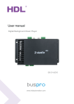
User Manual
Logic timer module
SB-DN-Logic960
User Manual
SB-DN-Logic960
INDEX
1. Overview................................................................................................... 1
1.1 General Information ............................................................................. 1
1.1.1 Description ................................................................................. 1
1.1.2 Mounting..................................................................................... 1
1.2 functionalities ................................................................................. 1
1.3 Device Description ............................................................................... 2
2. Technical Data .......................................................................................... 2
3. Installation ................................................................................................ 3
3.1 Wiring .................................................................................................. 3
4.2 HDL BUS Pro Description .................................................................... 3
4. Software Configurations ......................................................................... 4
4.1 Basic setting ........................................................................................ 4
4.1.1 Change the ID of the device........................................................... 4
4.1.2 Remark .......................................................................................... 5
4.2 Configurations ...................................................................................... 5
4.2.1 Equipment activation ...................................................................... 5
4.2.2 Input conditions .............................................................................. 5
4.3 system setting..................................................................................... 13
4.3.1: Date settings for timer ................................................................. 13
4.3.2 Geographic location settings ........................................................ 13
4.3.2.1 Geographic location .................................................................. 13
4.3.3 Method of prayer times ................................................................ 14
4.3.4 Summer time settings .................................................................. 14
5 applications ............................................................................................... 15
5. NOTES .................................................................................................... 22
Logic timer– User Manual
User Manual
SB-DN-Logic960
1. Overview
1.1 General Information
1.1.1 Description
SB-DN-Logic960 is an intelligent programmable logic controller which is developed by
HDL, it can control the system automatically by logic lines such as: - scene, channel
status, input status, date, time and so on. You can use AND, OR, NAD and NOR logic
blocks to build up different logics for different applications, moreover, it has real-time clock
so you can build up schedules too.
1.1.2 Mounting
Standard 35mm Din Rail Installation
Inside Distribution Box(DB)
1.2 functionalities
Supports 12 logic groups and each group have 20 logic tables.
Each logic table can set 4 logic input condition and 20 input targets.
Logical table input condition: Time, Date, Year, Week, Scene working status, external
device input status, Wall panel status, and security setting.
Logic relation: AND, OR, XOR, NAND
Logic timer – User Manual
1
User Manual
SB-DN-Logic960
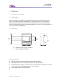
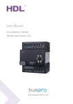
1.3 Device Description
a. LED indicator
b. programming button
c. HDL-bus pro
2. Technical Data
Electric Parameter :
Bus power
DC12~30V
Bus power consumption
15mA/DC24V
Environmental Condition:
Working temperature
-5℃~45℃
Working relative humidity
Up to 92%
Storage temperature
-40℃~+60℃
Storage relative humidity
10%~93%
Approved
CE
RoHS
Production information:
Dimensions
72×88×66 (mm)
Installation
35mm Din Rail installation
Protection degree
IP20
Logic timer – User Manual
2
User Manual
SB-DN-Logic960
3. Installation
3.1 Wiring
Please follow the wiring showed below strictly.
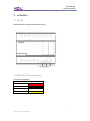
4.2 HDL BUS Pro Description
Connector Information
buspro
DC24V
Red
COM
Black
DATA-
White
DATA+
Yellow
Logic timer – User Manual
3
User Manual
SB-DN-Logic960
4. Software Configurations
4.1 Basic setting
4.1.1 Change the ID of the device
Each HDL-device has subnet and Device ID and each module’s Device ID must be unique
and different from other devices on the same Bus, the subnet ID should be the same as
the HDL-Bus gateway (typically the SB-DN-1IP or HDL-MBUS01IP.431).
Method One:
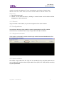
1. Run the HDL-BUS Pro Setup tool.
2. Long press the “programming button” and keep pressing it for 3 seconds until it turns to
a red color.
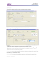
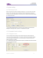
3. On the software, click ton “Address management”, and select
“Modify address (when device button is pressed)” option, it will show a window like
below:
4. click on “Indicate initial address”, then it will show the current subnet/device ID of this
Logic timer – User Manual
4
User Manual
SB-DN-Logic960
module. to modify the address, fill in the new address, and click the “Modify initial
address ”Click the “+Add” button, the device will be added to “ON-line devices “list.
Method two:
1- Run HDL-bus pro tool
2- Search for the online devices by clicking on search button and the device will be
displayed on “online device list”
4.1.2 Remark
To give a name to the module, so you can recognize it from other modules.
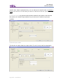
4.2 Configurations
As mentioned above the logic module is used for automating other HDL modules.
And in this tab, we will see how to setup a logic table with input conditions.
4.2.1 Equipment activation
If this option is unchecked, it means that the logic module has been disabled and will no
longer perform any process.
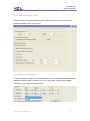
4.2.2 Input conditions
First select a logic table from the “logic No” list, double click on the blank black area to
start configuration and then select a logic relation from (AND, OR, XOR, NAND) according
to your requirements.
Logic timer – User Manual
5
User Manual
SB-DN-Logic960
-As the logic module is a very flexible automation device, there are many input conditions
that will be used to reach any possible logic, each logic table can have maximum of four
input conditions.
Below are the explanations of each logic input:-
Logic timer – User Manual
6
User Manual
SB-DN-Logic960
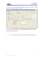
a) Year type:
This input is to select specific year, date or between years and dates.
b) Date type: You can specify date data with a numeric month.
Options:-At date point: select a designate or specific date for example: June 4th
-Date period: you can select interval of time (date), for example: from Oct 7th-Nov 30th
-Every month: this is the whole year settings.
c) Week type: you can select a specific week day or between weekdays (from specific day
to another) e.g.: from Monday- Friday
d) Time type: this is used to set a particular day time or before and after specific time.
Logic timer – User Manual
7
User Manual
SB-DN-Logic960
-specific time: select a particular time, you can also set the specific time as sunrise or
sunset (you need to set the time for sunrise and sunset on the system settings
tab)
e) Universal switch: is a general communication method for all modules, some devices
can send out UV switch to logic module. So you can set a UV switch as your input
condition.
f) Exterior input value
This function is used to detect an output value. For now it’s only used for temperature,
Logic timer – User Manual
8
User Manual
SB-DN-Logic960
g) Device scene status: you can put a dimmer/relay scene status as a condition for your
logic, so a target will be triggered when the scene is ON or OFF.
-Put the subnet/device ID of the target module, the area and scene number.
h) Device sequence status: you can put a dimmer/relay sequence status as a condition for
your logic, so a target will be triggered when the sequence is ON or OFF.
Logic timer – User Manual
9
User Manual
SB-DN-Logic960
i) Exterior universal status: this feature is used to monitor the status of an external
universal switch and send out command according to the UV switch status.
j) Device channel status: This is used to read dimmer/relay channel status, so when the
channel is ON or OFF, the logic can send out a command to trigger a target.
Logic timer – User Manual
10
User Manual
SB-DN-Logic960
k) Device curtain status: you can put curtain status as a condition for your logic, so a target
will be triggered when the curtain is ON or OFF.
l) Panel status: the logic module can read the status of the panel functions, including IR
function, Lock key of panel, AC power, cooling temperature, fan speed, AC mode , Ac
heating temperature and AC auto
m) Security settings: this is to read the status of the security module arming settings.
Logic timer – User Manual
11
User Manual
SB-DN-Logic960
4.2.3 Additional settings
a) Delay time settings
When a trigger is applied, the logic module will postpone the output according to the delay
time that you set on your logic table.
P.s: if you send many input commands to the logic module and there is a delay time, the
logic will calculate the delay time and the action maybe delayed longer than the expected
time.
b)
Automatically detect re-trigger enable
if this option selected means every time the logic module receives a command,
it will re-trigger the target again, no matter the target is already triggered or not.
Logic timer – User Manual
12
User Manual
SB-DN-Logic960
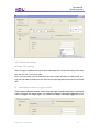
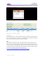
4.3 system setting
4.3.1 Date settings for timer
Before using the logic module and starting configuring it, you must set the current date
and time. The current date and time settings are used as standard timer settings for
functions that require date and time, you can set your PC’s date and time by just clicking
on “PC time “and “save”
-you can also broadcast the time to HDL-bus so other devices can receive the time
settings from the logic module , just tick on “ Broadcast Time” option.
4.3.2 Geographic location settings
4.3.2.1 Geographic location
You can manage location settings in logic module through the system settings tab.
You can also set the particular point of your place on the surface by setting the latitude
(LAT) and longitude (LONG) points, or you can just find your country and city in the
system by clicking on “location”
P.s:- configuring the location settings help the system to calculate the sunrise and sunset
time for that particular location
Logic timer – User Manual
13
User Manual
SB-DN-Logic960
4.3.3 Method of prayer times
Different countries may have different Islamic methods; you can set the prayer times
method according to your country here.
4.3.4 Summer time settings
As some countries use the summer time settings and The summer time implementation
period and regions differ by country, thus you can set the summer time settings
according to your region on logic module.
Logic timer – User Manual
14
User Manual
SB-DN-Logic960
5 applications
Application 1 – Irrigation schedule
Requirement
Turn on the irrigation at 9 a.m. on every Sunday for 40 minutes; end-user has a button to
enable/disable the schedule logic.
Note
The water valve is controlled by a relay channel of a Relay module.
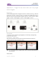
Configuration – Logic module
Logic (1):- it has three conditions 1-week type (Sunday), 2-time type (9am) and 3- UV (19)
should be ON,
Target (output):- The target relay must set ON
Logic (2):- its linked to logic (1), to do that:- a) Right click on logic(1) and select “ confirm
start point”
b) and then right click on Logic(2) and select “confirm end point”
-set delay time for logic(2), 40minutes in this example, so after 40 minutes it will be OFF
Target (output):- set the relay this time as OFF
Logic timer – User Manual
15
User Manual
SB-DN-Logic960
Configuration – Panel
Assign one key (button) to send the specified UV switch to the logic module, so you can
enable/disable the schedule from user panel, the mode should be Single ON/OFF..
Application 2 – Birthday remainder
Requirements:Remind the end-user the birthdays of his/her families and close friends in advance (so
that end-user has the time to prepare the presents), via voice (SB-Z-Audio or
HDL-MZBOX.20).
Note
The reminder voice files (.mp3 files) have been recorded and have been put in a folder
named “special” in the SD card, they are “015 birthday-grandma.mp3”, “016
birthday-me.mp3”, “017 birthday-wife.mp3”, “018 birthday-kids”, etc. The specific
Universal Switch number has specific meaning for SB-Z-Audio, 208 is to select SD, 150 is
to select the folder “special”, and 15 is to select “015 birthday-grandma.mp3”, for more
Universal Switch, please check “Z-Audio list.pdf”.
ftp://59.41.255.150/HDL-BUS/HDL-BUS%20Products/SB-Z-Audio/
Logic timer – User Manual
16
User Manual
SB-DN-Logic960
Configuration – Logic module
Set the pin as “year type” and select “specific date” option
Target (output):-
Application 3 – Timer for cooking
Requirement
Set up several timers – 1 minute, 3 minutes, 5 minutes, 10 minutes and 30 minutes, when
end-user press the button in the kitchen, a corresponding timer is started, the 30 second
down-count voice will start to play when the time is elapsing.
Note
The is voice files “019 timer-1m.mp3”, “020 timer-3m.mp3”, “021 timer-5m.mp3”, “022
timer-10m.mp3”, “023 timer-30m.mp3” have been put in the folder named “special” in the
SD card. The specific Universal Switch number has specific meaning for SB-Z-Audio, 208
is to select SD, 150 is to select the folder “special”, and 19 is to select “019 timer-1m.mp3”,
for more Universal Switch, please check “Z-Audio list.pdf”.
ftp://59.41.255.150/HDL-BUS/HDL-BUS%20Products/SB-Z-Audio/
Logic timer – User Manual
17
User Manual
SB-DN-Logic960
Configuration – Logic module
Target (output)
Configuration – Panel
Application 4 - Wake up scene
Requirement
Every morning at 8 a.m. on every weekday (Monday to Friday) and 10 a.m. on weekend
(Saturday and Sunday), wake end-user up by opening the curtain, playing a specific song,
turn up the volume slowly though (every 10 seconds, step up the volume). End-user has a
button to enable/disable the scene at previous night and another button to stop the music.
Note:The song “025 wakeup.mp3” has been put in the folder named “special” in the SD card.
The specific Universal Switch number has specific meaning for SB-Z-Audio, 208 is to
select SD, 150 is to select the folder “special”, and 25 is to select “025 wakeup.mp3”, 215
to 224 is for volume control, minimum to maximum, respectively. For more Universal
Switch, please check “Z-Audio list.pdf”.
ftp://59.41.255.150/HDL-BUS/HDL-BUS%20Products/SB-Z-Audio/
Logic timer – User Manual
18
User Manual
SB-DN-Logic960
Configuration – Logic module
Three conditions for each table scene:a) Week type (between weekdays)
b) time type (specific time)
c) UV switch
-connect the other tables to the first table and set them a delay to increase the volume of
the played song slowly
Targets (output):-
This is for the first table means the starting volume will be “voice28” UV-219,
Configuration – Panel
On the panel all we need is to send UV switch command to the logic module to
enable/disable the scene from the panel…
Logic timer – User Manual
19
User Manual
SB-DN-Logic960
Application 5 – Trigger the next scene when one of any toggle
switch is toggled.
Requirement
Use the existing toggle buttons to trigger the scenes in a dimmer in this way – When the
toggle switch is pressed, no matter the status of the toggle switch is ON or OFF as long as
there is an action, the scene should be changed to next one, (a circle): scence1->Switch
toggled -> scene2 -> Switch toggled -> scene3 -> Switch toggled -> scene1…
Acknowledge
A Hongkong customer raised this typical application, HDL RnD Dept. manager Dicky
provided the simple solution.
Configuration - Logic module
Setup some logic tables with some outputs, each logic should have two pins( two
conditions) and both of them should be UV switch
N.B:- The “Automatically detect re-trigger enable” option should be ticked (selected) in
each logic table
Targets (output)
Logic timer – User Manual
20
User Manual
SB-DN-Logic960
Each logic table will send out the fallowing:a) OFF command to UV-switch (21) {common UV switch for all the three tables}…
b) ON command to the next table (UV switch) and off to the other 2 tables
c) Also turn ON a specific scene…
E.g:- table (1) output should be like this….
Table (2) output..
Table (3) output
Configuration - Dry contact
On the dry contact first we need to assign three switches ( channels) to send commands
to the logic module by sending UV switch , for example in this solution we send UV(21)
which means the dry contact send commands to all the three tables because all of them
share UV(21)…
N.B:- The switch type should be
Mechanical switch ,
so there will be two
mechanical switch for each switch (mechanical switch ON and mechanical switch
Logic timer – User Manual
21
User Manual
SB-DN-Logic960
OFF) and both
output UV switch status should be ON
5. NOTES
Logic timer – User Manual
22
User Manual
SB-DN-Logic960
Logic timer – User Manual
23