1
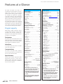
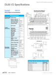
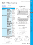
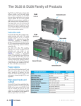
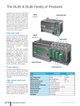
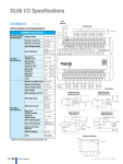
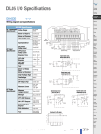
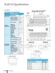
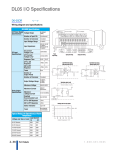
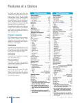
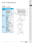
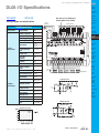
Prices as of April 15, 2015. Check Web site for most current prices.
DL06 I/O Specifications
Company
Information
Control Systems
Overview
D0-06AA
CLICK PLC
$314.00
Wiring diagram and specifications
Note: Refer to Power Budgeting for
Auxillary 24VDC current available.
Power
input wiring
Do-More
PLCs Overview
Do-More H2
PLC
Output point wiring
D0-06AA Specifications
AC Power Supply
Specifications
AC Input
Specifications
AC Output
Specifications
95-240
VAC
17-240
VAC
Do-More T1H
PLC
Voltage Range
95-240VAC
(40VA)
Number of Input Pts.
20
Number of Commons
5 (isolated)
Input Voltage Range
90-120VAC
Frequency Range
47-63Hz
DirectLOGIC
DL105
Input Current
8mA @ 100 VAC
at 50 Hz
10mA @ 100 VAC
at 60Hz
DirectLOGIC
DL205
On Current/Voltage
Level
OFF Current/
Voltage Level
OFF to ON
Response
ON to OFF
Response
Fuses
Number of Output
Points
DirectLOGIC
DL05/06
>6mA/75VAC
DirectLOGIC
DL305
<2mA/20VAC
DirectLOGIC
DL405
Productivity
Controller
Overview
<40ms
<40ms
Productivity
3000
None
Universal
Field I/O
16
Number of Commons
4 (isolated)
Output Voltage Range
17-240VAC
47-63Hz
Peak Voltage
264VAC
ON Voltage Drop
1.5 VAC>50mA
4.0VAC<50mA
Maximum Current
0.5A/pt
2.0A/common
Maximum
Leakage Current
Maximum
Inrush Current
Minimum Load
DirectLOGIC
PLCs Overview
4mA at 264VAC
Software
90-120
VAC
Input point wiring
C-More Micro
HMI
Equivalent input circuit
ViewMarq
Industrial
Marquees
Other HMI
9$&
Communications
10A for 10ms
Appendix
Book 1
10mA
OFF to ON Response
<1ms
ON to OFF Response
<1ms + 1/2 cycle
Fuses
None (external
recommended)
Terms and
Conditions
Equivalent output circuit
Derating chart for AC outputs
Book 1 (14.2)
www.automationdirect.com
C-More
HMI
DL05 / DL06 PLCs
eDS-41
Prices as of April 15, 2015. Check Web site for most current prices.
Features at a Glance
The DL05 and DL06 micro PLCs are
complete self-contained systems. The CPU,
power supply, and I/O are all included
inside the same housing. Option modules
are available to expand the capability
of each PLC family for more demanding
applications. The standard features of these
PLCs are extraordinary and compare favorably with larger and more expensive PLCs.
The specification tables to the right are
meant for quick reference only. Detailed
specifications and wiring information for
each model of the DL05 and DL06 PLCs
can be found in those specific sections.
Program capacity
Most boolean ladder instructions require
a single word of program memory. Other
instructions, such as timers, counters, etc.,
require two or more words. Data is stored in
V‑memory in 16-bit registers.
Performance
The performance characteristics shown in the
tables represent the amount of time required
to read the inputs, solve the Relay Ladder
Logic program and update the outputs.
Instructions
A complete list of instructions is available
at the end of this section.
Communications
The DL05 and DL06 offer powerful
communication features normally found
only on more expensive PLCs.
Special features
The DC input and DC output PLCs offer
high-speed counting or pulse output.
Option module slots allow for discrete
I/O expansion, analog I/O, or additional
communication options.
DL05 CPU Specifications
System capacity
DL06 CPU Specifications
System capacity
Total memory available (words)…………………… 6K
Ladder memory (words)…………………………2,048
V-memory (words)…………………………… 4,096
User V-memory………………………………3,968
Non-volatile user V-memory……………………128
Battery backup………………………………… Yes1
Total built-in I/O………………………………… 14
Inputs…………………………………………8
Outputs…………………………………………6
I/O expansion……………………………………Yes1
Total memory available (words)………………… 14.8K
Ladder memory (words)…………………………7680
V-memory (words)………………………………7616
User V-memory………………………………7488
Non-volatile user V-memory……………………128
Built-in battery backup (D2-BAT-1)…………………Yes
Total I/O…………………………………………36
Inputs…………………………………………20
Outputs………………………………………16
I/O expansion………………………………… Yes1
Performance
Contact execution (Boolean)…………………… 0.6µs
Typical scan (1K Boolean)2 ……………………1-2ms.
Contact execution (Boolean)…………………… 0.7µs
Typical scan (1K Boolean)2…………………1.5-3ms.
Instructions and diagnostics
RLL ladder style………………………………… Yes
RLLPLUS/flowchart style (Stages)………………Yes/256
Run-time editing…………………………………Yes
Supports Overrides………………………………Yes
Scan……………………………………Variable/fixed
Number of Instructions……………………………133
Types of Instructions:
Control relays…………………………………512
Timers………………………………………128
Counters……………………………………128
Immediate I/O…………………………………Yes
Subroutines……………………………………Yes
For/next loops…………………………………Yes
Timed interrupt……………………………… Yes
Integer math………………………………… Yes
Floating-point math…………………………… No
PID…………………………………………Yes
Drum sequencers………………………………Yes
Bit of word……………………………………Yes
ASCII print……………………………………Yes
Real-time clock/calendar…………………………Yes1
Internal diagnostics………………………………Yes
Password security……………………………… Yes
System and user error log…………………………No
Communications
Built-in ports……………………………Two RS-232C
Protocols supported:
K-sequence (proprietary protocol)……………… Yes
DirectNet master/slave…………………………Yes
Modbus RTU master/slave………………………Yes
ASCII out…………………………………… Yes
Baud rate
Port 1…………………………9,600 baud (fixed)
Port 2…………………selectable 300-38,400 baud
……………………………………(default 9,600)
Specialty Features
Filtered inputs……………………………………Yes3
Interrupt input……………………………………Yes3
High speed counter…………………………Yes, 5kHz3
Pulse output………………………………Yes, 7kHz3
Pulse catch input…………………………………Yes3
1- These features are available with use of
certain option modules. Option module specifications are located later in this section.
2- Our 1K program includes contacts, coils, and
scan overhead. If you compare our products
to others, make sure you include their scan
overhead.
3- Input features only available on units with DC
inputs and output features only available on
units with DC outputs.
Performance
Instructions and diagnostics
RLL ladder style………………………………… Yes
RLLPLUS/flowchart style (Stages)…………… Yes/1024
Run-time editing…………………………………Yes
Supports Overrides………………………………Yes
Scan……………………………………Variable/fixed
Number of Instructions……………………………229
Types of Instructions:
Control relays……………………………… 1024
Timers………………………………………256
Counters……………………………………128
Immediate I/O…………………………………Yes
Subroutines……………………………………Yes
For/next loops…………………………………Yes
Table functions……………………………… Yes
Timed interrupt……………………………… Yes
Integer math………………………………… Yes
Trigonometric functions…………………………Yes
Floating-point math……………………………Yes
PID…………………………………………Yes
Drum sequencers………………………………Yes
Bit of word……………………………………Yes
Number type conversion……………………… Yes
ASCII in, out, print…………………………… Yes
LCD instruction……………………………… Yes
Real-time clock/calendar………………………… Yes
Internal diagnostics………………………………Yes
Password security……………………………… Yes
System and user error log…………………………No
Communications
Built-in ports:………………………… One RS-232C
…………One multi-function RS232C/RS422/RS485
NOTE: RS485 is for MODBUS RTU only.
Protocols supported:
K-sequence (proprietary protocol)……………… Yes
DirectNet master/slave…………………………Yes
Modbus RTU master/slave………………………Yes
ASCII in/out………………………………… Yes
Baud rate
Port 1…………………………9,600 baud (fixed)
Port 2…………………selectable 300-38,400 baud
……………………………………(default 9,600)
Specialty Features
Filtered inputs……………………………………Yes3
Interrupt input……………………………………Yes3
High speed counter…………………………Yes, 7kHz3
Pulse output………………………………Yes, 10kHz3
Pulse catch input…………………………………Yes3
1- These features are available with use of
certain option module. Option module specifications are located later in this section.
2- Our 1K program includes contacts, coils, and
scan overhead. If you compare our products
to others, make sure you include their scan
overhead.
3- Input features only available on units with DC
inputs and output features only available on
units with DC outputs.
Book 1 (14.2)
eDS-20
DL05 / DL06 PLCs
1-800-633-0405
Prices as of April 15, 2015. Check Web site for most current prices.
Features at a Glance
Company
Information
Control Systems
Overview
DirectSOFT software
The DL05 and DL06 PLCs use the same
familiar DirectSOFT programming software that our larger PLCs use. A FREE
version of DirectSOFT gives you all the
great features of the full version, but with a
100-word PLC program download limitation. For programs larger than 100 words,
the full package is required. The FREE
PC-DS100 software may be sufficient to
program the DL05 and DL06. If you are
programming with a full package version
prior to v6.0, you will need v2.4 or later
for the DL05 PLCs and v4.0 or later for the
DL06. We always recommend the latest
version for the most robust features. See
the DirectLOGIC Overview section DL in
this catalog for a complete description
of DirectSOFT including features, part
numbers of programming packages and
upgrades.
Programming
Handheld programmer....D2-HPP. . . . . . . . . . . . . . . $321.00
DirectSOFT Programming for Windows
PC-DSOFT6. . . . . . . . . . . . . . . . . . . . . . . . . . . . . . . . $395.00
PC-DS100. . . . . . . . . . . . . . . . . . . . . . . . . . . . . . . . . . . . . . Free
PC-R60-U (upgrade) . . . . . . . . . . . . . . . . . . . . . . . . . $179.00
External power inputs
CLICK PLC
Mounting tab
Input status indicators
Do-More
PLCs Overview
Mode switch
Communication ports
Output status indicators
Do-More H2
PLC
Do-More T1H
PLC
DirectLOGIC
PLCs Overview
Mode status
indicators
Communication status
indicators
Removable
terminal
block
DirectLOGIC
DL05/06
DirectLOGIC
DL105
DirectLOGIC
DL205
DirectLOGIC
DL305
DirectLOGIC
DL405
External power inputs
Discrete output terminals
Discrete input terminals
Discrete output terminals
Option module slot
Productivity
Controller
Overview
Productivity
3000
Hardware features diagrams
Universal
Field I/O
Removable
terminal
block
Option module slots
Software
C-More
HMI
C-More Micro
HMI
Mode status
indicators
Output status indicators
Input status indicators
Communication status
indicators
ViewMarq
Industrial
Marquees
Other HMI
Communications
Appendix
Book 1
Terms and
Conditions
Mode switch
Discrete input terminals
Removable
terminal
block
Communication ports
Mounting tab
Book 1 (14.2)
www.automationdirect.com
DL05 / DL06 PLCs
eDS-21
Prices as of April 15, 2015. Check Web site for most current prices.
Product Dimensions and Installation
It is important to understand the installation requirements for your DL05 or DL06
system. Your knowledge of these requirements will help ensure that your system
operates within its environmental and
electrical limits.
Note: T here is a minimum clearance requirement
of 2” (51mm) between the panel door
(or any devices mounted in the panel door)
and the nearest DL05 component.
Plan for safety
This catalog should never be used as a
replacement for the user manual. You can
purchase, download free, or view online
the user manuals for these products. The
D0-USER-M is the publication for the
DL05 PLCs, and the D0-06USER-M is
the publication for the DL06 PLCs. The
D0-OPTIONS-M is the user manual for
the option modules. These user manuals
contain important safety information that
must be followed. The system installation
should comply with all appropriate electrical codes and standards.
Temperature probe
2"
50mm
min
Power source
2"
50mm
min
2"
50mm
min
Panel ground terminal
Bus b
ar
Panel
Star washers
Earth
ground
Ground braid copper lugs
Star washers
Panel or single
point ground
See the Enclosure
section to find an enclosure
that fits your application
Temperature probe
1.5"
38mm
min
Environmental Specifications
for DL05 and DL06
Power source
1.5"
38mm
min
Storage Temperature
Ambient Operating
Temperature
Panel ground terminal
Bus b
ar
Earth
ground
Note: There is a minimum clearance requirement of 1.5” (38mm)
between the panel door (or any devices mounted in the
panel door) and the nearest DL06 component.
1.5"
38mm
min
Ambient Humidity
-4º F-158ºF
(-20ºC to 70ºC)
32ºF-131ºF
(0º to 55ºC)
5 to 95% relative
humidity
(non-condensing)
Vibration Resistance
MIL STD 810C
Method 514.2
Shock Resistance
MIL STD 810C
Method 516.2
Noise Immunity
NEMA (ICS3-304)
Atmosphere
No corrosive gases
Book 1 (14.2)
eDS-22
DL05 / DL06 PLCs
1-800-633-0405
Prices as of April 15, 2015. Check Web site for most current prices.
Product Dimensions and Installation
Company
Information
Control Systems
Overview
CLICK PLC
Unit dimensions and
mounting orientation
Do-More
PLCs Overview
Do-More H2
PLC
DL05 and DL06 PLCs must be mounted
properly to ensure ample airflow for
cooling purposes. It is important to follow
the unit orientation requirements and
to verify that the PLC’s dimensions are
compatible with your application. Notice
particularly the grounding requirements
and the recommended cabinet clearances.
Do-More T1H
PLC
DirectLOGIC
PLCs Overview
DirectLOGIC
DL05/06
DirectLOGIC
DL105
Mounting orientation
DirectLOGIC
DL205
DirectLOGIC
DL305
DirectLOGIC
DL405
Productivity
Controller
Overview
Productivity
3000
Universal
Field I/O
Software
C-More
HMI
Mounting orientation
C-More Micro
HMI
ViewMarq
Industrial
Marquees
Other HMI
Communications
Appendix
Book 1
Terms and
Conditions
Book 1 (14.2)
www.automationdirect.com
DL05 / DL06 PLCs
eDS-23
Prices as of April 15, 2015. Check Web site for most current prices.
Choosing the I/O Type
Company
Information
Control Systems
Overview
Inputs
Outputs
Part Number I/O Type/ Sink or Voltage I/O Type/ Sink or Voltage/Current
Commons source Ranges Commons Source Ratings
D0-06AA
AC/5
N/A
90-120VAC AC/4
D0-06AR
AC/5
N/A
90-120VAC Relay/4
D0-06DA
DC/5
D0-06DD1
DC/5
Sink or
source
Sink or
source
Sink or
source
Sink or
source
Sink or
source
Sink or
source
Sink or
source
D0-06DD2
DC/5
D0-06DR
DC/5
D0-06DD1-D DC/5
D0-06DD2-D DC/5
D0-06DR-D DC/5
12-24VDC
AC/4
12-24VDC
DC/4
17-240VAC, 0.5A
50/60 Hz
6-27VDC, 2A
N/A
6-240VAC, 2A
17-240VAC, 0.5A
N/A
50/60Hz
6-27VDC, 0.5A (Y0-Y1)
Sink
6-27VDC, 1.0A (Y2-Y17)*
12-24VDC, 0.5A (Y0-Y1)
Source
12-24VDC, 1.0A (Y2-Y17)
6-27VDC, 2A
N/A
6-240VAC, 2A
6-27VDC, 0.5A (Y0-Y1)
Sink
6-27VDC, 1.0A (Y2-Y17)*
12-24VDC, 0.5A (Y0-Y1)
Source
12-24VDC, 1.0A (Y2-Y17)
6-27VDC, 2A
N/A
6-240VAC, 2A
N/A
12-24VDC
DC/4
12-24VDC
Relay/4
12-24VDC
DC/4
12-24VDC
DC/4
12-24VDC
Relay/4
Price
$314.00
$293.00
$293.00
$251.00
By using option modules, you can add
analog inputs or outputs to your DL05
or DL06 PLC. The table below shows
the input and output types at a glance.
Detailed specifications are provided
later in this section.
Inputs
Part Number
$272.00
$251.00
$251.00
$272.00
Discrete I/O Option Moduless
Price
Voltage/Current
Ratings
N/A
6-27VDC, 1A
6-240VAC, 1A
$64.00
DC/4/2
Sink
6-27VDC, 0.3A
$64.00
Outputs Price
No. Input Type No.
Output
Type
F0-04AD-1
4
0-20mA or 0
4-20mA
F0-04AD-2
4
0-5VDC or 0
0-10VDC
F0-08ADH-1
8
F0-08ADH-2
8
F0-04DAH-1
0
N/A
4
4-20mA $144.00
F0-08DAH-1
0
N/A
8
4-20mA $197.00
F0-04DAH-2
0
N/A
4
0-10VDC $140.00
F0-08DAH-2
0
N/A
8
0-10VDC $186.00
F0-4AD2DA-1 4
0-20mA or 2
4-20mA
F0-2AD2DA-2 2
0-5VDC or 2
0-10VDC
0-5VDC or 2
0-10VDC
0-20mA
or
$192.00
4-20mA
0-5VDC
or
$155.00
0-10VDC
0-5VDC
or
$218.00
0-10VDC
N/A
$83.00
N/A
$120.00
0
N/A
$134.00
0-5VDC or 0
0-10VDC
N/A
$144.00
0-20mA
D0-07CDR
DC/4/1
D0-08CDD1
DC/4/2
Sink or
source
Sink or
source
N/A
N/A
N/A
Relay/8/2
N/A
6-27VDC, 1A
6-240VAC, 1A
$64.00
D0-10ND3
DC/10/2
12-24VDC
N/A
N/A
N/A
$54.00
D0-10ND3F
DC/10/2
Sink or
source
Sink or
source
12-24VDC
N/A
N/A
N/A
$62.00
F0-4AD2DA-2 4
D0-10TD1
N/A
N/A
N/A
DC/10/2
Sink
6-27VDC, 0.3A
$63.00
F0-04RTD
4
RTD
0
N/A
$207.00
D0-10TD2
N/A
N/A
N/A
DC/10/2
Source
12-24VDC, 0.3A
$63.00
4
N/A
$207.00
DC/16/4
20-28VDC
N/A
N/A
N/A
$58.00
Thermocouple /
Voltage
0
D0-16ND3
Sink or
source
F0-04THM*
D0-16TD1
N/A
N/A
N/A
DC/16/2
Sink
6-27VDC, 0.1A
$64.00
D0-16TD2
N/A
N/A
N/A
DC/16/2
Source
12-24VDC, 0.1A
$64.00
$41.00
$50.00
D0-08TR
12-24VDC
Relay/3/1
12-24VDC
F0-04TRS
N/A
N/A
N/A
Relay/4/4
N/A
5-30VDC, 3A
5-125VAC, 3A
F0-08NA-1
AC/8/2
N/A
80-132VAC
90-150VDC
N/A
N/A
N/A
F0-08SIM
8-pt. Input simulator
$37.00
Communications and Specialty Option Modules
Part Number
H0-ECOM100
D0-DEVNETS
H0-CTRIO
H0-CTRIO2
H0-PSCM
D0-DCM
F0-CP128
Description
Ethernet Communications Module 10/100 Mbit
DeviceNET Slave Module
High Speed Counter I/O Module
Profibus Slave Communications Module
Serial Communications Module
ASCII CoProcessor Module
Price
$216.00
$100.00
Retired
Retired
$309.00
$146.00
$192.00
Power budgeting
No power budgeting is necessary for
the DL05. The built-in power supply
is sufficient for powering the base
unit, any of the option modules, the
handheld programmer, and even a
DV1000 operator interface.
Power budgeting is necessary for the
DL06. With four option module slots
and an optional LCD display, it is
necessary to verify that sufficient power
is available for all optional devices.
Power budgeting is described in detail
on page 2-29 and in the DL06 User
Manual.
DL05 / DL06 PLCs
Do-More H2
PLC
Do-More T1H
PLC
DirectLOGIC
DL05/06
DirectLOGIC
DL105
DirectLOGIC
DL205
DirectLOGIC
DL305
DirectLOGIC
DL405
Productivity
Controller
Overview
Productivity
3000
Universal
Field I/O
Software
C-More
HMI
C-More Micro
HMI
ViewMarq
Industrial
Marquees
Other HMI
Communications
* See module specifications page for thermocouple
types and voltage input ranges supported
Book 1 (14.2)
www.automationdirect.com
Do-More
PLCs Overview
DirectLOGIC
PLCs Overview
Analog I/O Option Modules
$251.00
* These outputs must be derated to 0.6A for EN61131-2 compliance.
Inputs
Outputs
Part Number I/O Type/ Sink or Voltage I/O Type/ Sink or
Number/
Number/
Commons source Ranges Commons Source
CLICK PLC
Analog I/O
DL06 Base Unit I/O Table
eDS-25
Appendix
Book 1
Terms and
Conditions
Prices as of April 15, 2015. Check Web site for most current prices.
Networking the DL05 and DL06
All DL05 and DL06 PLCs have built-in
networking capability. The DL05 family
offers two 6-pin, RS‑232 ports. You
can use these ports for programming,
networking, or connecting an operator
interface device. The RS-232 ports
support point-to-point communications
using the optional D0-CBL cable. If you
need to create a multi-drop network or
require longer distances between devices,
you can use the FA-ISOCON at each
DL05 to convert the RS-232 signal to
RS-422 or RS-485.
Optional Ethernet
communication modules
Need to connect to a high speed HMI or
computer system? We offer a 100Base-T
Ethernet communications module. You
can use the H0-ECOM100 Ethernet
communication module with our Stride
Ethernet switches or with most off-theshelf Ethernet hubs or switches. The
H0-ECOM100 option module plugs into
any DL05 or DL06 PLC and supports the
industry standard Modbus TCP protocol.
Point-to-point
The DL06 family of PLCs offers even
greater communications flexibility. Port 1
is a fixed baud rate port identical to port
1 on the DL05 PLCs, but port 2 is a multifunction port that can be used as RS-232,
RS-422, or RS-485 (Modbus/ASCII only)
without using external converters. This
allows you to create multi-drop networks
with minimal installation headaches.
12’ crossover cable = D0-CBL
maximum distance 50ft (15m)
Protocols supported
Each port is capable of communicating
using K-sequence, DirectNET and
Modbus RTU protocols. Port 1 can only
be a slave for each of the protocols.
Port 2 can serve as a K-sequence slave
or a network master or slave for either
DirectNET or Modbus RTU protocols.
Master
Slave
Multi-drop
Serial Bus Protocols
We also offer option modules that allow
you to connect a DL05 or DL06 PLC to a
variety of networks as a slave device. Our
D0-DEVNETS (DeviceNet) and H0-PSCM
(PROFIBUS) option modules plug into
any DL05 or DL06 PLC. The D0-DCM
Data Communications module supports
DirectNET and Modbus RTU protocols.
ZL-CMA15
FA-ISOCON
ZIPLink communication
adatper modules
The ZIPLink communications adapter
modules offer fast and convenient screw
terminal connection for the bottom port
of the DL06 CPU. The adapter modules
are RS232/422 DIP switch selectable
and are offered with or without indicating
LEDs and surge protection. See the
Wiring Solutions section in this catalog
for more information.
ZL-CMA15L
Maximum distance of 3,300 ft. (1000m)
Book 1 (14.2)
eDS-26
DL05 / DL06 PLCs
1-800-633-0405
Prices as of April 15, 2015. Check Web site for most current prices.
Ports, Status Indicators, and Modes
Company
Information
Control Systems
Overview
Port 1
Port 1 is a 6-pin, fixed configuration port
and has the same pin assignments on the
DL05 and the DL06. Please refer to the table
and diagrams on this page. This port can be
used to connect to an HPP, DirectSOFT, an
operator interface, or other external device.
Features include:
• 9600 baud
• 8 data bits
• Odd parity
• 1 start bit, 1 stop bit
• Station address of 1
• Asynchronous, half-duplex, DTE
Protocols supported (as slave):
• K sequence, DirectNET, Modbus RTU
DL05 & DL06 Port 1 Pin Descriptions
1
2
3
4
5
6
Port 2
Port 2 is a configurable port on both the
DL05 and the DL06 PLCs. The DL05 PLC
uses a 6-pin modular connector and offers
RS-232 communications only. The DL06
PLC uses a 15-pin HD-sub connector
and offers RS-232, RS-422, or RS-485
communications. Please refer to the table
and diagrams on this page for more information. This port can be used to connect
to an HPP, DirectSOFT, an operator interface, or other external device. Features of
port 2 include:
• 300, 600, 1200, 2400, 4800, 9600 (default),
19,200, 38,400 baud
• 8 data bits
• Odd (default), even, or no parity
• 1 start bit, 1 stop bit
• Station address:
0V
Power (-) connection (GND)
5V
Power (+) connection
1 (default)
RXD
Receive data (RS-232C)
TXD
Transmit data (RS-232C)
1-90 DirectNET, K sequence
5V
Power (+) connection
0V
Power (-) connection (GND)
DL05 Port 2 Pin Descriptions
1
2
3
4
5
6
0V
Power (-) connection (GND)
5V
Power (+) connection
RXD
Receive data (RS-232C)
TXD
Transmit data (RS-232C)
RTS
Ready to send
0V
Power (-) connection (GND)
DL06 Port 2 Pin Descriptions
6-pin Female Modular Connector
DL06
6-pin Female
Modular Connector
15-pin Female
D-sub Connector
Status Indicators
Indicator Status Meaning
PWR
RUN
CPU
1
2
3
4
5
6
7
8
9
10
11
12
13
14
15
5V
Power (+) connection
TXD
Transmit data (RS-232C)
RXD
Receive data (RS-232C)
RTS
Ready to send (RS232C)
CTS
Clear to send (RS232C)
RXD-
Receive data (-) (RS-422/485)
0V
Power (-) connection (GND)
0V
Power (-) connection (GND)
Power good
OFF
Power failure
ON
CPU is in Run Mode
OFF
CPU is in Stop or Program Mode
ON
CPU self diagnostics error
OFF
CPU self diagnostics good
ON
Data is being transmitted by the
CPU-Port 1
OFF
No data is being transmitted by
the CPU-Port 1
ON
Data is being received by the
CPU-Port 1
OFF
No data is being received by the
CPU-Port 1
ON
Data is being transmitted by the
CPU-Port 2
OFF
No data is being transmitted by
the CPU-Port 2
ON
Data is being received by the
CPU-Port 2
OFF
No data is being received by the
CPU-Port 2
RX1
TX2
RX2
DL05 and DL06 mode
switches
Mode
Switch
Position
CPU Action
CPU is forced into the RUN mode if no
RUN (Run errors are encountered. No program
are allowed by the programProgram) changes
ming/monitoring device.
RUN PROGRAM and the TEST modes are
TERM
available. Mode and program changes
allowed by the programming/moni(Terminal) are
toring device.
CPU is forced into the STOP mode. No
changes are allowed by the programSTOP
ming/monitoring device.
Use the optional low profile 15-pin adapter
to make option module wiring easier.
D0-06ADPTR
TXD+ Transmit data (+) (RS-422/485
TXD-
Transmit data (-) (RS-422/485)
RTS+
Ready to send (+) (RS-422/485)
RTS-
Ready to send (-) (RS-422/485)
RXD+ Receive data (+) (RS-422/485)
CTS+ Clear to send (+) (RS-422/485)
CTS-
Clear to send (-) (RS-422/485)
Book 1 (14.2)
www.automationdirect.com
DL05 / DL06 PLCs
CLICK PLC
Do-More
PLCs Overview
Do-More H2
PLC
Do-More T1H
PLC
ON
TX1
1-247 Modbus RTU
• Asynchronous, half-duplex, DTE
Protocols supported:
• K sequence (slave), DirectNET
(master/slave), Modbus (master/slave)
DL05
DL05 and DL06 status
indicators
eDS-27
DirectLOGIC
PLCs Overview
DirectLOGIC
DL05/06
DirectLOGIC
DL105
DirectLOGIC
DL205
DirectLOGIC
DL305
DirectLOGIC
DL405
Productivity
Controller
Overview
Productivity
3000
Universal
Field I/O
Software
C-More
HMI
C-More Micro
HMI
ViewMarq
Industrial
Marquees
Other HMI
Communications
Appendix
Book 1
Terms and
Conditions
Prices as of April 15, 2015. Check Web site for most current prices.
ASCII and Modbus Instructions
ASCII instructions
for DL06
The DL06 PLC supports several easyto-use instructions, which allow ASCII
strings to be read into or written from the
communication ports when using either
the CPU port 2, or the D0-DCM Data
Communications Module port 2.
Raw ASCII: CPU/DCM Port 2 can be used
for either reading or writing raw ASCII
strings, but not for both.
Embedded ASCII: With these instructions,
you can use the DL06 PLC to locate ASCII
strings embedded within a supported
protocol via CPU/DCM Port.
Receiving ASCII strings
1. ASCII IN (AIN) - This instruction configures CPU/DCM Port 2 for raw ASCII
input strings, with parameters such as
fixed and variable length ASCII strings,
termination characters, byte swapping
options, and instruction control bits.
Use barcode scanners, weigh scales,
etc., to write raw ASCII input strings
into CPU/DCM Port 2 based on the
AIN instruction’s parameters.
Writing ASCII strings
More ASCII instructions
1. Print from V-memory (PRINTV) - Use
this instruction to write raw ASCII strings
out of CPU/
DCM port 2
to a display
panel, serial
printer, etc.
The instruction features
the starting
V-memory
address,
string length,
byte swapping options,
etc. When the instruction’s permissive
bit is enabled, the string is written to
CPU/DCM Port 2.
ASCII Find (AFIND) - Finds where a specific
portion of the ASCII string is located in
continuous V-memory addresses.
2. Print to V-memory (VPRINT) - Use this
instruction to create pre-coded ASCII
strings in the PLC (e.g. alarm messages).
When the instruction’s permissive bit
is enabled, the message is loaded
into a pre-defined V-memory address
location. Then the PRINTV instruction
may be used to write the pre-coded
ASCII string out of CPU/DCM Port 2.
American, European, and Asian Time/
Dates tamps are supported.
3. Print Message (PRINT) - This existing
instruction can be used to create precoded ASCII strings in the PLC. When the
instruction’s permissive bit is enabled,
the string is written to CPU/DCM Port 2.
The VPRINT/PRINTV instruction combination is more powerful and flexible
than the PRINT instruction.
2. Write embedded ASCII strings directly
to V-memory from an external HMI (or
similar master device). The ASCII string
is transmitted through CPU/DCM Port
2 using any supported communications protocol. This method uses the
familiar RX/WX instructions previously
available.
4. If the DL06 PLC is a network master,
the Network Write (WX) can be used to
write embedded ASCII data to an HMI
or slave device directly from V-memory.
This is done via a supported communications protocol using CPU/DCM Port 2.
ASCII Extract (AEX) - Extracts a specific
portion (usually some data value) from the
ASCII find location or other known ASCII
data location.
Compare V-memory (CMPV) - This
instruction is used to compare two blocks
of V-memory addresses and is usually
used to detect a change in an ASCII string.
Compared data types must be of the same
format (e.g. BCD, ASCII, etc.).
Swap Bytes (SWAPB) - Swaps V-memory
bytes on ASCII data that was written
directly to V-memory from an external HMI
or similar master device via a communications protocol. The AIN and AEX instructions have a built-in byte swap feature.
The F0-CP128 option module is also
available for more extensive ASCII
communications.
Modbus RTU
instructions for DL06
The DL06 CPU/DCM port 2 supports
Modbus Read/Write instructions that
simplify setup. The MRX and MWX instructions allow you to use native Modbus
addressing, eliminating the need for octal
to decimal conversions.
Function Codes 05 and 06 and the ability
to read Slave Exception Codes have been
added. These flexible instructions allow
the user to select the following parameters
within one instruction window:
• 584/984 or 484 Modbus data type
• Slave node (0-247)
• Function code
• Starting master/slave memory
address
• Number of bits
• Exception code starting address
3. If the DL06 is used as a network master,
the Network Read instruction (RX) can
be used to read embedded ASCII data
from a network slave device. Again,
the ASCII string would be transmitted
through CPU/DCM Port 2, using any
supported communications protocol.
Book 1 (14.2)
eDS-28
DL05 / DL06 PLCs
1-800-633-0405
Prices as of April 15, 2015. Check Web site for most current prices.
Power Budgeting for the DL06
D0-06xx
Power supplied
D0-06xx-D
24 VDC (mA)
1500mA
300mA
2000mA
200mA
1500mA
none
DL06 Base Unit Power Required
Part Number 5 VDC (mA)
24 VDC (mA)
D0-06AA
800mA
none
D0-06AR
900mA
none
D0-06DA
800mA
none
For power budgeting, start by considering
the power supplied by the base unit. All
DL06 PLCs supply the same amount of 5
VDC power. Only the AC units offer 24
VDC auxiliary power.
D0-06DD1
600mA
280mA*
D0-06DD2
600mA
none
D0-06DR
950mA
none
D0-06DD1-D
600mA
none
Be aware of the trade-off between 5 VDC
power and 24 VDC power. The amount of
5 VDC power available depends on the
amount of 24 VDC power being used,
and the amount of 24 VDC power available depends on the amount of 5 VDC
power consumed. Determine the amount
of internally supplied power from the table
to the right.
D0-06DD2-D
600mA
none
D0-06DR-D
950mA
none
* Only if auxiliary 24VDC power is connected to V+ terminal.
DL06 Power Consumed
by Other Devices
Part Number
5 VDC (mA)
24 VDC (mA)
D0-06LCD
50mA
none
D2-HPP
200mA
none
DV-1000
C-more
Micro-Graphic
150mA
none
210mA
none
Power Budgeting Example
5VDC power 24VDC power
(mA)
(mA)
Power Source
A
D0-06DD1
(select row A or B) B
1500mA
300mA
2000mA
200mA
Power required by option
modules
power 24VDC power
Current Required 5VDC
(mA)
(mA)
Next, subtract the amount of power
required by the option modules you are
planning to use. Again, remember to
subtract both 5 VDC and 24 VDC.
If your power budget analysis shows
surplus power available, you should have
a workable configuration.
DL05/06 Power Consumed
by Option Modules
DL06 Power Supplied by Base Units
Part Number 5 VDC (mA)
Power is supplied from two sources: the
internal base unit power supply and, if
required, an external supply (customer
furnished). The D0-06xx (AC powered)
PLCs supply a limited amount of 24 VDC
power. The 24 VDC output can be used to
power external devices.
Because of the different I/O configurations available in the DL06 family, the
power consumed by the base unit itself
varies from model to model. Subtract the
amount of power required by the base unit
from the amount of power supplied by the
base unit. Be sure to subtract 5 VDC and
24 VDC amounts.
Control Systems
Overview
CLICK PLC
The DL06 has four option module slots.
To determine whether the combination
of modules you select will have sufficient
power, you will need to perform a power
budget calculation.
Power required by base
unit
Company
Information
D0-06DD1
600mA
280mA*
D0-16ND3
35mA
0
D0-10TD1
150mA
0
D0-08TR
280mA
0
F0-4AD2DA-1
100mA
0
D0-06LCD
50mA
0
Total Used
Remaining
1215mA
280mA
A
285mA
20mA
B
785mA
note 1
Part Number 5 VDC (mA) 24 VDC (mA)
130mA
none
D0-07CDR
100mA
none
D0-08CDD1
280mA
none
D0-08TR
35mA
none
D0-10ND3
35mA
none
D0-10ND3F
150mA
none
D0-10TD1
150mA
none
D0-10TD2
35mA
none
D0-16ND3
200mA
none
D0-16TD1
200mA
none
D0-16TD2
250mA
none
F0-04TRS
5mA
none
F0-08NA-1
50mA
none
F0-04AD-1
75mA
none
F0-04AD-2
25mA
25mA
F0-08ADH-1
25mA
25mA
F0-08ADH-2
25mA
150mA
F0-04DAH-1
25mA
220mA
F0-08DAH-1
25mA
30mA
F0-04DAH-2
25mA
30mA
F0-08DAH-2
50mA
30mA
F0-2AD2DA-2
100mA
40mA
F0-4AD2DA-1
100mA
none
F0-4AD2DA-2
70mA
none
F0-04RTD
30mA
none
F0-04THM
45mA
none
D0-DEVNETS
530mA
none
H0-PSCM
250mA
none
H0-CTRIO2
300mA
none
H0-ECOM100
1mA
none
F0-08SIM
250 mA
none
D0-DCM
150 mA
none
F0-CP128
1 mA
none
F0-08SIM
Do-More H2
PLC
Do-More T1H
PLC
DirectLOGIC
PLCs Overview
DirectLOGIC
DL05/06
DirectLOGIC
DL105
DirectLOGIC
DL205
DirectLOGIC
DL305
DirectLOGIC
DL405
Productivity
Controller
Overview
Productivity
3000
Universal
Field I/O
Software
C-More
HMI
C-More Micro
HMI
ViewMarq
Industrial
Marquees
Other HMI
Communications
Appendix
Book 1
Terms and
Conditions
* Auxiliary 24 VDC used to power V+ terminal of D0-06DD1 sinking outputs.
Note 1: If the PLC’s auxiliary 24 VDC power source is used to power
the sinking outputs, use power choice A, above.
Book 1 (14.2)
www.automationdirect.com
Do-More
PLCs Overview
DL05 / DL06 PLCs
eDS-29
Prices as of April 15, 2015. Check Web site for most current prices.
DL06 LCD Display
The optional D0-06LCD ($83.00) is a
cost effective LCD display panel that is
easy to install. This device is available
exclusively for the DL06 PLCs.
One simple ladder instruction is used to
set up the display. The LCD configuration
instruction is available in DirectSOFT,
version 4.0 or later.
Buzzer
16 X 2 backlit display
Note: The D2-HPP handheld programmer
does not support DL06 LCD configuration.
Keypad navigation
The 16 character x 2 row display mounts
directly on the face of the PLC. The LCD is
backlit and is accessible using the seven
function keys on the front of the display.
Monitor or change data
values
You can view V-memory registers, I/O
status, PLC mode, or system errors without
interrupting the PLC’s control function.
Display messages required for alarm or
monitoring purposes can be preprogrammed or imported as ASCII data.
Password protection
Two layers of password protection
prevent unauthorized changes to clock
and calendar setup and V-memory data
values. Individuals with password authorization can change clock, calender,
V-memory values, force bits on or off, etc.
The DL06 User Manual (D0-06USER-M)
describes more fully the installation and
operation of the D0-06LCD. Be sure to
consult this manual before installing the
DL06 LCD. The manual is available free
on our Web site, or it can be purchased
separately.
Snap-in installation
The display installs easily into any model
DL06 PLC.
The piezoelectric buzzer can be configured to provide pushbutton feedback.
Seven function keys on the face of the
LCD display provide navigation through
messages or menu items. Messages fall
into two categories:
• Error messages
• User-defined preprogrammed messages
At power-up the default screen is
displayed. The default screen can be userdefined.
Seven menu choices allow you to view
or change all accessible data values (see
next page).
Note: Remove power to the PLC before
installing or removing the LCD display.
Remove the plastic cover (located between
the input and output terminals) by sliding
the cover to the left. In its place, slide in
the LCD display until it snaps into place.
Display or change individual bits (up to
16 bits per screen) or 32-bit double word
values from V-memory.
Left
Up
Right
Down
Escape
Menu
Enter
Book 1 (14.2)
eDS-30
DL05 / DL06 PLCs
1-800-633-0405