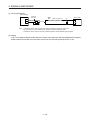
1
General-Purpose AC Servo
MR-JE-_B SERVO AMPLIFIER INSTRUCTION MANUAL
MODEL
MR-JE-B SERVOAMPLIFIER
INSTRUCTIONMANUAL
MODEL
CODE
1CW750
SH (NA) 030152-B (1508) MEE
Printed in Japan
This Instruction Manual uses recycled paper.
Specifications are subject to change without notice.
B
HEAD OFFICE : TOKYO BLDG MARUNOUCHI TOKYO 100-8310
SSCNET
/H Interface AC Servo
MODEL
MR-JE-_B
SERVO AMPLIFIER
INSTRUCTION MANUAL
B
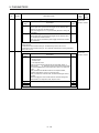
Safety Instructions
Please read the instructions carefully before using the equipment.
To use the equipment correctly, do not attempt to install, operate, maintain, or inspect the equipment until
you have read through this Instruction Manual, Installation guide, and appended documents carefully. Do not
use the equipment until you have a full knowledge of the equipment, safety information and instructions.
In this Instruction Manual, the safety instruction levels are classified into "WARNING" and "CAUTION".
WARNING
CAUTION
Note that the
Indicates that incorrect handling may cause hazardous conditions,
resulting in death or severe injury.
Indicates that incorrect handling may cause hazardous conditions,
resulting in medium or slight injury to personnel or may cause physical
damage.
CAUTION level may lead to a serious consequence according to conditions.
Please follow the instructions of both levels because they are important to personnel safety.
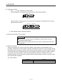
What must not be done and what must be done are indicated by the following diagrammatic symbols.
Indicates what must not be done. For example, "No Fire" is indicated by
Indicates what must be done. For example, grounding is indicated by
.
.
In this Instruction Manual, instructions at a lower level than the above, instructions for other functions, and so
on are classified into "POINT".
After reading this Instruction Manual, keep it accessible to the operator.
A- 1
1. To prevent electric shock, note the following.
WARNING
Before wiring and inspections, turn off the power and wait for 15 minutes or more until the charge lamp
turns off. Otherwise, an electric shock may occur. In addition, when confirming whether the charge lamp
is off or not, always confirm it from the front of the servo amplifier.
Ground the servo amplifier and servo motor securely.
Any person who is involved in wiring and inspection should be fully competent to do the work.
Do not attempt to wire the servo amplifier and servo motor until they have been installed. Otherwise, it
may cause an electric shock.
Do not operate switches with wet hands. Otherwise, it may cause an electric shock.
The cables should not be damaged, stressed, loaded, or pinched. Otherwise, it may cause an electric
shock.
To prevent an electric shock, always connect the protective earth (PE) terminal (marked with ) of the
servo amplifier to the protective earth (PE) of the cabinet.
To avoid an electric shock, insulate the connections of the power supply terminals.
2. To prevent fire, note the following.
CAUTION
Install the servo amplifier, servo motor, and regenerative resistor on incombustible material. Installing
them directly or close to combustibles will lead to smoke or a fire.
Always connect a magnetic contactor between the power supply and the power supply (L1, L2, and L3)
of the servo amplifier, in order to configure a circuit that shuts down the power supply on the side of the
servo amplifier’s power supply. If a magnetic contactor is not connected, continuous flow of a large
current may cause smoke or a fire when the servo amplifier malfunctions.
Always connect a molded-case circuit breaker, or a fuse to each servo amplifier between the power
supply and the power supply (L1, L2, and L3) of the servo amplifier, in order to configure a circuit that
shuts down the power supply on the side of the servo amplifier’s power supply. If a molded-case circuit
breaker or fuse is not connected, continuous flow of a large current may cause smoke or a fire when the
servo amplifier malfunctions.
When using a regenerative resistor, switch power off with the alarm signal. Otherwise, a regenerative
transistor malfunction or the like may overheat the regenerative resistor, causing smoke or a fire.
When you use a regenerative option with an MR-JE-40B to MR-JE-100B, remove the built-in
regenerative resistor and wiring from the servo amplifier.
Provide adequate protection to prevent screws and other conductive matter, oil and other combustible
matter from entering the servo amplifier and servo motor.
A- 2
3. To prevent injury, note the following.
CAUTION
Only the voltage specified in the Instruction Manual should be applied to each terminal. Otherwise, a
burst, damage, etc. may occur.
Connect cables to the correct terminals. Otherwise, a burst, damage, etc. may occur.
Ensure that polarity (+/-) is correct. Otherwise, a burst, damage, etc. may occur.
The servo amplifier heat sink, regenerative resistor, servo motor, etc. may be hot while power is on or for
some time after power-off. Take safety measures, e.g. provide covers, to avoid accidentally touching the
parts (cables, etc.) by hand.
4. Additional instructions
The following instructions should also be fully noted. Incorrect handling may cause a malfunction, injury,
electric shock, fire, etc.
(1) Transportation and installation
CAUTION
Transport the products correctly according to their mass.
Stacking in excess of the specified number of product packages is not allowed.
Do not hold the lead wire of the built-in regenerative resistor when transporting the servo amplifier.
Install the servo amplifier and the servo motor in a load-bearing place in accordance with the Instruction
Manual.
Do not get on or put heavy load on the equipment.
The equipment must be installed in the specified direction.
Leave specified clearances between the servo amplifier and the cabinet walls or other equipment.
Do not install or operate the servo amplifier and servo motor which have been damaged or have any
parts missing.
Do not block the intake and exhaust areas of the servo amplifier. Otherwise, it may cause a malfunction.
Do not drop or strike the servo amplifier and servo motor. Isolate them from all impact loads.
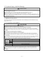
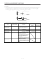
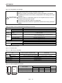
When you keep or use the equipment, please fulfill the following environment.
Item
Ambient
temperature
Ambient
humidity
Environment
Operation
Storage
Operation
Storage
Ambience
Altitude
Vibration resistance
0 ˚C to 55 ˚C (non-freezing)
-20 ˚C to 65 ˚C (non-freezing)
90%RH or less (non-condensing)
Indoors (no direct sunlight); no corrosive gas, inflammable gas, oil mist or dust
1000 m or less above sea level
5.9 m/s2, at 10 Hz to 55 Hz (directions of X, Y and Z axes)
When the product has been stored for an extended period of time, contact your local sales office.
When handling the servo amplifier, be careful about the edged parts such as corners of the servo
amplifier.
A- 3
CAUTION
The servo amplifier must be installed in a metal cabinet.
When fumigants that contain halogen materials, such as fluorine, chlorine, bromine, and iodine, are used
for disinfecting and protecting wooden packaging from insects, they cause malfunction when entering our
products. Please take necessary precautions to ensure that remaining materials from fumigant do not
enter our products, or treat packaging with methods other than fumigation, such as heat treatment.
Additionally, disinfect and protect wood from insects before packing the products.
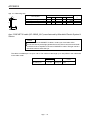
(2) Wiring
CAUTION
Before removing the CNP1 connector from MR-JE-40B to MR-JE-100B, disconnect the lead wires of the
regenerative resistor from the CNP1 connector.
Wire the equipment correctly and securely. Otherwise, the servo motor may operate unexpectedly.
Do not install a power capacitor, surge killer, or radio noise filter (optional FR-BIF) on the servo amplifier
output side.
To avoid a malfunction, connect the wires to the correct phase terminals (U, V, and W) of the servo
amplifier and servo motor.
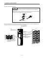
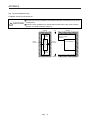
Connect the servo amplifier power output (U, V, and W) to the servo motor power input (U, V, and W)
directly. Do not let a magnetic contactor, etc. intervene. Otherwise, it may cause a malfunction.
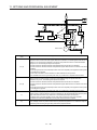
Servo amplifier
U
V
W
U
Servo motor
Servo amplifier
U
U
V
V
V
M
W
Servo motor
M
W
W
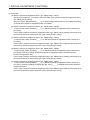
The connection diagrams in this Instruction Manual are shown for sink interfaces, unless stated
otherwise.
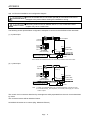
The surge absorbing diode installed to the DC relay for control output should be fitted in the specified
direction. Otherwise, the emergency stop and other protective circuits may not operate.
Servo amplifier
24 V DC
DOCOM
Control output
signal
Servo amplifier
DOCOM
24 V DC
Control output
signal
RA
For sink output interface
RA
For source output interface
When the cable is not tightened enough to the terminal block, the cable or terminal block may generate
heat because of the poor contact. Be sure to tighten the cable with specified torque.
Connecting a servo motor of the wrong axis to U, V, W, or CN2 of the servo amplifier may cause a
malfunction.
A- 4
(3) Test run and adjustment
CAUTION
Before operation, check the parameter settings. Improper settings may cause some machines to operate
unexpectedly.
Never adjust or change the parameter values drastically as doing so will make the operation unstable.
Do not get close to moving parts during the servo-on status.
(4) Usage
CAUTION
When it is assumed that a hazardous condition may occur due to a power failure or product malfunction,
use a servo motor with an external brake to prevent the condition.
Do not disassemble, repair, or modify the equipment.
Before resetting an alarm, make sure that the run signal of the servo amplifier is off in order to prevent a
sudden restart. Otherwise, it may cause an accident.
Use a noise filter, etc. to minimize the influence of electromagnetic interference. Electromagnetic
interference may be given to the electronic equipment used near the servo amplifier.
Burning or breaking a servo amplifier may cause a toxic gas. Do not burn or break it.
Use the servo amplifier with the specified servo motor.
The electromagnetic brake on the servo motor is designed to hold the motor shaft and should not be
used for ordinary braking.
For such reasons as service life and mechanical structure (e.g. where a ball screw and the servo motor
are coupled via a timing belt), the electromagnetic brake may not hold the motor shaft. To ensure safety,
install a stopper on the machine side.
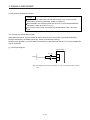
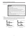
(5) Corrective actions
CAUTION
When it is assumed that a hazardous condition may occur due to a power failure or product malfunction,
use a servo motor with an electromagnetic brake or external brake to prevent the condition.
Configure an electromagnetic brake circuit so that it is activated also by an external emergency stop
switch.
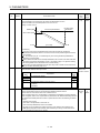
Contacts must be opened when ALM
(Malfunction) or MBR (Electromagnetic
brake interlock) turns off.
Contacts must be opened
with the emergency stop switch.
Servo motor
RA
B
24 V DC
U
Electromagnetic brake
When any alarm has occurred, eliminate its cause, ensure safety, and deactivate the alarm before
restarting operation.
Provide an adequate protection to prevent unexpected restart after an instantaneous power failure.
A- 5
(6) Maintenance, inspection and parts replacement
CAUTION
With age, the electrolytic capacitor of the servo amplifier will deteriorate. To prevent a secondary
accident due to a malfunction, it is recommended that the electrolytic capacitor be replaced every 10
years when it is used in general environment. For replacement, please contact your local sales office.
When using a servo amplifier whose power has not been turned on for a long time, contact your local
sales office.
(7) General instruction
To illustrate details, the equipment in the diagrams of this Instruction Manual may have been drawn
without covers and safety guards. When the equipment is operated, the covers and safety guards must
be installed as specified. Operation must be performed in accordance with this Instruction Manual.
DISPOSAL OF WASTE
Please dispose a servo amplifier, battery (primary battery) and other options according to your local laws and
regulations.
EEP-ROM life
The number of write times to the EEP-ROM, which stores parameter settings, etc., is limited to 100,000. If
the total number of the following operations exceeds 100,000, the servo amplifier may malfunction when the
EEP-ROM reaches the end of its useful life.
Write to the EEP-ROM due to parameter setting changes
Write to the EEP-ROM due to device changes
Compliance with global standards
Refer to appendix 4 for the compliance with global standards.
«About the manual»
You must have this Instruction Manual and the following manuals to use this servo. Ensure to prepare
them to use the servo safely.
Relevant manuals
Manual name
MELSERVO-JE Servo Amplifier Instruction Manual (Troubleshooting)
MELSERVO HG-KN_/HG-SN_ Servo Motor Instruction Manual
EMC Installation Guidelines
A- 6
Manual No.
SH(NA)030166
SH(NA)030135
IB(NA)67310
«Cables used for wiring»
Wires mentioned in this Instruction Manual are selected based on the ambient temperature of 40 ˚C.
«U.S. customary units»
U.S. customary units are not shown in this manual. Convert the values if necessary according to the
following table.
Quantity
Mass
Length
Torque
Moment of inertia
Load (thrust load/axial load)
Temperature
SI (metric) unit
1 [kg]
1 [mm]
1 [N•m]
1 [(× 10-4 kg•m2)]
1 [N]
N [°C] × 9/5 + 32
A- 7
U.S. customary unit
2.2046 [lb]
0.03937 [inch]
141.6 [oz•inch]
5.4675 [oz•inch2]
0.2248 [lbf]
N [°F]
MEMO
A- 8
CONTENTS
1. FUNCTIONS AND CONFIGURATION
1- 1 to 1-12
1.1 Summary ........................................................................................................................................... 1- 1
1.2 Function block diagram..................................................................................................................... 1- 2
1.3 Servo amplifier standard specifications ............................................................................................ 1- 4
1.4 Combinations of servo amplifiers, servo motors, and controllers ..................................................... 1- 5
1.4.1 Combinations of servo amplifiers and servo motors .................................................................. 1- 5
1.4.2 Compatible controller ................................................................................................................. 1- 5
1.5 Function list ....................................................................................................................................... 1- 6
1.6 Model designation ............................................................................................................................. 1- 8
1.7 Structure ........................................................................................................................................... 1- 9
1.7.1 Parts identification ...................................................................................................................... 1- 9
1.8 Configuration including peripheral equipment ................................................................................. 1-11
2. INSTALLATION
2.1
2.2
2.3
2.4
2.5
2.6
2- 1 to 2- 8
Installation direction and clearances ................................................................................................ 2- 2
Keep out foreign materials ................................................................................................................ 2- 3
Encoder cable stress ........................................................................................................................ 2- 4
SSCNET III cable laying ................................................................................................................... 2- 4
Inspection items ................................................................................................................................ 2- 6
Parts having service lives ................................................................................................................. 2- 7
3. SIGNALS AND WIRING
3- 1 to 3-42
3.1 Input power supply circuit ................................................................................................................. 3- 2
3.2 I/O signal connection example......................................................................................................... 3-11
3.2.1 For sink I/O interface ................................................................................................................. 3-11
3.2.2 For source I/O interface ............................................................................................................ 3-12
3.3 Explanation of power supply system ............................................................................................... 3-13
3.3.1 Signal explanations ................................................................................................................... 3-13
3.3.2 Power-on sequence .................................................................................................................. 3-14
3.3.3 Wiring CNP1 and CNP2 ............................................................................................................ 3-15
3.4 Connectors and pin assignment ...................................................................................................... 3-17
3.5 Signal (device) explanations ............................................................................................................ 3-18
3.5.1 Input device ............................................................................................................................... 3-18
3.5.2 Output device ............................................................................................................................ 3-19
3.5.3 Power supply ............................................................................................................................. 3-20
3.6 Forced stop deceleration function ................................................................................................... 3-21
3.6.1 Forced stop deceleration function ............................................................................................. 3-21
3.6.2 Base circuit shut-off delay time function ................................................................................... 3-22
3.6.3 Vertical axis freefall prevention function ................................................................................... 3-23
3.6.4 Residual risks of the forced stop function (EM2) ...................................................................... 3-23
3.7 Alarm occurrence timing chart ......................................................................................................... 3-24
3.7.1 When you use the forced stop deceleration function ................................................................ 3-24
3.7.2 When you do not use the forced stop deceleration function ..................................................... 3-25
3.7.3 Hot line forced stop function...................................................................................................... 3-26
3.8 Interfaces ......................................................................................................................................... 3-32
1
3.8.1 Internal connection diagram ...................................................................................................... 3-32
3.8.2 Detailed explanation of interfaces ............................................................................................. 3-33
3.8.3 Source I/O interfaces ................................................................................................................ 3-34
3.9 SSCNET III cable connection .......................................................................................................... 3-35
3.10 Servo motor with an electromagnetic brake .................................................................................. 3-37
3.10.1 Safety precautions .................................................................................................................. 3-37
3.10.2 Timing chart ............................................................................................................................ 3-39
3.11 Grounding ...................................................................................................................................... 3-42
4. STARTUP
4- 1 to 4-14
4.1 Switching power on for the first time ................................................................................................. 4- 1
4.1.1 Startup procedure ...................................................................................................................... 4- 1
4.1.2 Wiring check ............................................................................................................................... 4- 2
4.1.3 Surrounding environment ........................................................................................................... 4- 3
4.2 Startup .............................................................................................................................................. 4- 4
4.3 Switch setting and display of the servo amplifier .............................................................................. 4- 5
4.3.1 Axis selection rotary switch (SW1)............................................................................................. 4- 5
4.3.2 Scrolling display ......................................................................................................................... 4- 7
4.3.3 Status display of an axis ............................................................................................................ 4- 8
4.4 Test operation .................................................................................................................................. 4-10
4.5 Test operation mode ........................................................................................................................ 4-10
4.5.1 Test operation mode in MR Configurator2 ................................................................................ 4-11
4.5.2 Motor-less operation in the controller........................................................................................ 4-13
5. PARAMETERS
5- 1 to 5-38
5.1 Parameter list .................................................................................................................................... 5- 1
5.1.1 Basic setting parameters ([Pr. PA_ _ ])...................................................................................... 5- 2
5.1.2 Gain/filter setting parameters ([Pr. PB_ _ ]) ............................................................................... 5- 3
5.1.3 Extension setting parameters ([Pr. PC_ _ ]) .............................................................................. 5- 4
5.1.4 I/O setting parameters ([Pr. PD_ _ ]) ......................................................................................... 5- 6
5.1.5 Extension setting 2 parameters ([Pr. PE_ _ ])............................................................................ 5- 7
5.1.6 Extension setting 3 parameters ([Pr. PF_ _ ]) ............................................................................ 5- 8
5.2 Detailed list of parameters ............................................................................................................... 5-10
5.2.1 Basic setting parameters ([Pr. PA_ _ ])..................................................................................... 5-10
5.2.2 Gain/filter setting parameters ([Pr. PB_ _ ]) .............................................................................. 5-18
5.2.3 Extension setting parameters ([Pr. PC_ _ ]) ............................................................................. 5-30
5.2.4 I/O setting parameters ([Pr. PD_ _ ]) ........................................................................................ 5-33
5.2.5 Extension setting 2 parameters ([Pr. PE_ _ ])........................................................................... 5-36
5.2.6 Extension setting 3 parameters ([Pr. PF_ _ ]) ........................................................................... 5-37
6. NORMAL GAIN ADJUSTMENT
6- 1 to 6-28
6.1 Different adjustment methods ........................................................................................................... 6- 1
6.1.1 Adjustment on a single servo amplifier ...................................................................................... 6- 1
6.1.2 Adjustment using MR Configurator2 .......................................................................................... 6- 2
6.2 One-touch tuning .............................................................................................................................. 6- 3
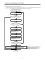
6.2.1 One-touch tuning flowchart ........................................................................................................ 6- 5
6.2.2 Display transition and operation procedure of one-touch tuning ............................................... 6- 7
6.2.3 Caution for one-touch tuning ..................................................................................................... 6-17
2
6.3 Auto tuning ....................................................................................................................................... 6-18
6.3.1 Auto tuning mode ...................................................................................................................... 6-18
6.3.2 Auto tuning mode basis............................................................................................................. 6-19
6.3.3 Adjustment procedure by auto tuning ....................................................................................... 6-20
6.3.4 Response level setting in auto tuning mode ............................................................................. 6-21
6.4 Manual mode ................................................................................................................................... 6-22
6.5 2 gain adjustment mode .................................................................................................................. 6-25
7. SPECIAL ADJUSTMENT FUNCTIONS
7- 1 to 7-30
7.1 Filter setting ...................................................................................................................................... 7- 1
7.1.1 Machine resonance suppression filter ....................................................................................... 7- 1
7.1.2 Adaptive filter II........................................................................................................................... 7- 4
7.1.3 Shaft resonance suppression filter............................................................................................. 7- 6
7.1.4 Low-pass filter ............................................................................................................................ 7- 7
7.1.5 Advanced vibration suppression control II ................................................................................. 7- 7
7.1.6 Command notch filter ................................................................................................................ 7-11
7.2 Gain switching function .................................................................................................................... 7-13
7.2.1 Applications ............................................................................................................................... 7-13
7.2.2 Function block diagram ............................................................................................................. 7-14
7.2.3 Parameter.................................................................................................................................. 7-15
7.2.4 Gain switching procedure ......................................................................................................... 7-18
7.3 Tough drive function ........................................................................................................................ 7-22
7.3.1 Vibration tough drive function.................................................................................................... 7-22
7.3.2 Instantaneous power failure tough drive function ..................................................................... 7-24
7.4 Model adaptive control disabled ...................................................................................................... 7-26
7.5 Lost motion compensation function ................................................................................................. 7-27
8. TROUBLESHOOTING
8- 1 to 8- 8
8.1 Explanation for the lists ..................................................................................................................... 8- 1
8.2 Alarm list ........................................................................................................................................... 8- 2
8.3 Warning list ....................................................................................................................................... 8- 6
9. DIMENSIONS
9- 1 to 9- 4
9.1 Servo amplifier .................................................................................................................................. 9- 1
9.2 Connector ......................................................................................................................................... 9- 4
10. CHARACTERISTICS
10- 1 to 10- 8
10.1 Overload protection characteristics .............................................................................................. 10- 1
10.2 Power supply capacity and generated loss .................................................................................. 10- 3
10.3 Dynamic brake characteristics ...................................................................................................... 10- 5
10.3.1 Dynamic brake operation ....................................................................................................... 10- 5
10.3.2 Permissible load to motor inertia when the dynamic brake is used ....................................... 10- 6
10.4 Cable bending life ......................................................................................................................... 10- 7
10.5 Inrush current at power-on ........................................................................................................... 10- 7
3
11. OPTIONS AND PERIPHERAL EQUIPMENT
11- 1 to 11-48
11.1 Cable/connector sets .................................................................................................................... 11- 1
11.1.1 Combinations of cable/connector sets ................................................................................... 11- 2
11.1.2 SSCNET III cable ................................................................................................................... 11- 5
11.1.3 Battery cable and junction battery cable ................................................................................ 11- 7
11.2 Regenerative option...................................................................................................................... 11- 8
11.2.1 Combination and regenerative power .................................................................................... 11- 8
11.2.2 Selection of regenerative option ............................................................................................ 11- 9
11.2.3 Parameter setting .................................................................................................................. 11-10
11.2.4 Connection of regenerative option ........................................................................................ 11-11
11.2.5 Dimensions ........................................................................................................................... 11-15
11.3 Junction terminal block PS7DW-20V14B-F (recommended) ...................................................... 11-17
11.4 MR Configurator2 ........................................................................................................................ 11-18
11.4.1 Specifications ........................................................................................................................ 11-18
11.4.2 System requirements ............................................................................................................ 11-19
11.4.3 Precautions for using USB communication function ............................................................. 11-20
11.5 Battery .......................................................................................................................................... 11-21
11.5.1 Selection of battery ............................................................................................................... 11-21
11.5.2 MR-BAT6V1SET-A battery ................................................................................................... 11-22
11.5.3 MR-BT6VCASE battery case ................................................................................................ 11-26
11.5.4 MR-BAT6V1 battery .............................................................................................................. 11-32
11.6 Selection example of wires .......................................................................................................... 11-33
11.7 Molded-case circuit breakers, fuses, magnetic contactors ......................................................... 11-34
11.8 Power factor improving AC reactor.............................................................................................. 11-35
11.9 Relay (recommended) ................................................................................................................. 11-36
11.10 Noise reduction techniques ....................................................................................................... 11-37
11.11 Earth-leakage current breaker ................................................................................................... 11-43
11.12 EMC filter (recommended) ........................................................................................................ 11-45
12. ABSOLUTE POSITION DETECTION SYSTEM
12- 1 to 12- 4
12.1 Summary....................................................................................................................................... 12- 1
12.1.1 Features ................................................................................................................................. 12- 1
12.1.2 Configuration .......................................................................................................................... 12- 2
12.1.3 Parameter setting ................................................................................................................... 12- 2
12.1.4 Confirmation of absolute position detection data ................................................................... 12- 2
12.2 Battery ........................................................................................................................................... 12- 3
12.2.1 Using the MR-BAT6V1SET-A battery .................................................................................... 12- 3
12.2.2 Using the MR-BT6VCASE battery case................................................................................. 12- 4
APPENDIX
App. - 1 to App. -18
App. 1 Peripheral equipment manufacturer (for reference).............................................................. App.- 1
App. 2 Handling of AC servo amplifier batteries for the United Nations Recommendations on the
Transport of Dangerous Goods ............................................................................................ App.- 1
App. 3 Symbol for the new EU Battery Directive .............................................................................. App.- 3
App. 4 Compliance with global standards ........................................................................................ App.- 3
App. 5 SSCNET III cable (SC-J3BUS_M-C) manufactured by Mitsubishi Electric System &
Service ................................................................................................................................. App.-14
App. 6 Low-voltage directive ........................................................................................................... App.-15
4
App. 7 When turning on or off the input power supply with DC power supply ................................ App.-16
App. 8 When using the hot line forced stop function in combination with MR-J4-_B servo
amplifier ................................................................................................................................ App.-17
App. 9 Optional data monitor function ............................................................................................. App.-18
5
MEMO
6
1. FUNCTIONS AND CONFIGURATION
1. FUNCTIONS AND CONFIGURATION
1.1 Summary
POINT
Refer to section 1.4.2 for compatible controllers.
The Mitsubishi general-purpose AC servo MELSERVO-JE series have limited functions with keeping high
performance based on MELSERVO-J4 series.
The MR-JE-_B servo amplifier is connected to controllers, including a servo system controller, on the highspeed synchronous network SSCNET III/H. The servo amplifier directly receives a command from a
controller to drive a servo motor.
SSCNET III/H achieves high-speed communication of 150 Mbps full duplex with high noise immunity due to
the SSCNET III optical cables. Large amounts of data can be exchanged in real-time between the controller
and the servo amplifier. Servo monitor information can be stored in the upper information system and used
for control.
With one-touch tuning and real-time auto tuning, you can easily and automatically adjust the servo gains
according to the machine.
The tough drive function, drive recorder function, and preventive maintenance support function strongly
support machine maintenance.
The servo amplifier has a USB communication interface. Therefore, you can connect the servo amplifier to
the personal computer with MR Configurator2 installed to perform the parameter setting, test operation, gain
adjustment, and others.
The servo motor equipped with an absolute position encoder whose resolution is 131072 pulses/rev will
enable a high-accuracy positioning.
1- 1
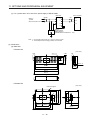
1. FUNCTIONS AND CONFIGURATION
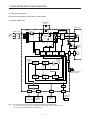
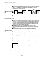
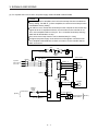
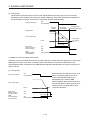
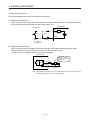
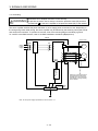
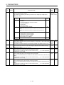
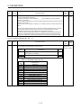
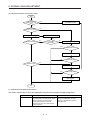
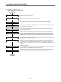
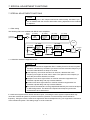
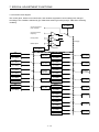
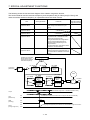
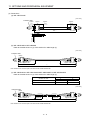
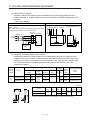
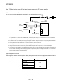
1.2 Function block diagram
The function block diagram of this servo is shown below.
(1) MR-JE-100B or less
Regenerative
option
MCCB
(Note 2)
Power
supply
MC
Diode
stack Relay
L1
Servo motor
C
P+
Dynamic
brake circuit
(Note 1)
U
L2
U
L3
+
Current
detector
Regenerative
TR
U
U
U
V
V
W
W
M
CHARGE
lamp
RA
Control
circuit
power
Base
amplifier
Voltage
detection
Overcurrent
protection
Current
detection
B1
ElectroB magnetic
brake
B2
CN2
24 V DC
Encoder
Model
position
control
Virtual
encoder
Model
speed
control
Stepdown
circuit
Virtual
motor
CN4
Position
command
input
Model position Model speed Model torque
Actual
position
control
Actual
speed
control
Current
control
USB
I/F Control
CN1A
CN1B
Servo system
controller or
servo amplifier
Servo
amplifier
or cap
CN3
CN5
Digital I/O
control
Note 1. The built-in regenerative resistor is not provided for MR-JE-10B and MR-JE-20B.
2. For 1-phase 200 V AC to 240 V AC, connect the power supply to L1 and L3. Leave L2 open.
For the power supply specifications, refer to section 1.3.
1- 2
Personal
computer
USB
Battery
(for absolute position
detection system)
1. FUNCTIONS AND CONFIGURATION
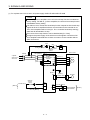
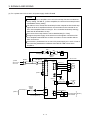
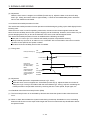
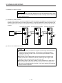
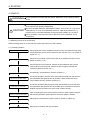
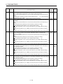
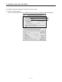
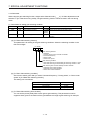
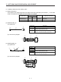
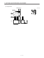
(2) MR-JE-200B or more
Regenerative
option
P+
MCCB
(Note 1)
Power
supply
MC
C
D
Servo motor
N- (Note 2)
Diode
stack Relay
Dynamic
brake circuit
U
U
V
V
W
W
L1
U
L2
U
L3
+
Current
detector
Regenerative
TR
U
M
CHARGE
lamp
RA
Cooling fan
Control
circuit
power
Base
amplifier
Voltage
detection
Overcurrent
protection
Current
detection
B1
ElectroB magnetic
brake
B2
CN2
24 V DC
Encoder
Model
position
control
Virtual
encoder
Model
speed
control
Stepdown
circuit
Virtual
motor
CN4
Position
command
input
Model position Model speed Model torque
Actual
position
control
Actual
speed
control
Battery
(for absolute position
detection system)
Current
control
USB
I/F Control
CN1A
CN1B
Servo system
controller or
servo amplifier
Servo
amplifier
or cap
CN3
Digital I/O
control
CN5
Personal
computer
USB
Note 1. A 1-phase 200 V AC to 240 V AC power supply may be used with the servo amplifier of MR-JE-200B. For 1-phase 200 V AC
to 240 V AC, connect the power supply to L1 and L2. Leave L3 open. For the power supply specifications, refer to section 1.3.
2. This terminal is for manufacturer adjustment. Leave this terminal open.
1- 3
1. FUNCTIONS AND CONFIGURATION
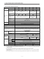
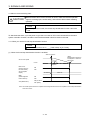
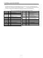
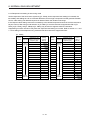
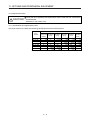
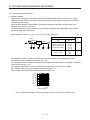
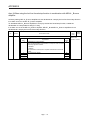
1.3 Servo amplifier standard specifications
Model: MR-JE-
10B
Rated voltage
Rated current
Output
[A]
Power supply
input
Interface
power supply
[A]
Permissible voltage
fluctuation
Permissible frequency
fluctuation
Power supply
[kVA]
capacity
Inrush current
[A]
Voltage
Current capacity
[A]
Control method
Dynamic brake
SSCNET III/H communication cycle
(Note 3)
Communication function
Protective functions
Compliance
to standards
CE marking
UL standard
Structure (IP rating)
Close
mounting
(Note 4)
Environment
Mass
1.5
40B
70B
100B
200B
300B
2.8
3-phase 170 V AC
5.8
6.0
11.0
11.0
3-phase
200 V AC
to 240 V
AC, 50
Hz/60 Hz
3-phase or 1-phase 200 V AC to 240 V AC, 50
Hz/60 Hz
Voltage/frequency
Rated current
(Note 1)
1.1
20B
3-phase power supply
input
1-phase power supply
input
Operation
Ambient
temperature Storage
Operation
Ambient
humidity
Storage
Ambience
Altitude
Vibration resistance
[kg]
0.9
1.5
2.6
3-phase or 1-phase 200
V AC to 240 V AC, 50
Hz/60 Hz (Note 5)
3.8
3-phase or 1-phase 170 V AC to 264 V AC
5.0
10.5
3-phase or 1-phase 170
V AC to 264 V AC
(Note 5)
14.0
3-phase
170 V AC
to 264 V
AC
Within ±5%
Refer to section 10.2.
Refer to section 10.5.
24 V DC ± 10%
(Note 2) 0.1
Sine-wave PWM control, current control method
Built-in
0.444 ms, 0.888 ms
USB: Connection to a personal computer or others (MR Configurator2-compatible)
Overcurrent shut-off, regenerative overvoltage shut-off, overload shut-off (electronic thermal),
servo motor overheat protection, encoder error protection, regenerative error protection,
undervoltage protection, instantaneous power failure protection, overspeed protection, and
error excessive protection
LVD: EN 61800-5-1
EMC: EN 61800-3
MD: EN ISO 13849-1, EN 61800-5-2, EN 62061
UL 508C
Force cooling, open
Natural cooling, open (IP20)
(IP20)
Possible
Possible
Impossible
0 ˚C to 55 ˚C (non-freezing)
-20 ˚C to 65 ˚C (non-freezing)
90%RH or lower (non-condensing)
Indoors (no direct sunlight); no corrosive gas, inflammable gas, oil mist or dust
1000 m or less above sea level
2
5.9 m/s , at 10 Hz to 55 Hz (directions of X, Y and Z axes)
0.8
1.5
2.1
Note 1. This value is applicable when a 3-phase power supply is used.
2. The current capacity 0.1 A is applicable when all I/O signals are used. The current capacity can be decreased by reducing the
number of I/O points.
3. The communication cycle depends on the controller specifications and the number of axes connected.
4. When closely mounting the servo amplifier, operate them at the ambient temperatures of 0 ˚C to 45 ˚C or at 75% or smaller
effective load ratio.
5. When using 1-phase 200 V AC to 240 V AC power supply, operate the servo amplifier at 75% or smaller effective load ratio.
1- 4
1. FUNCTIONS AND CONFIGURATION
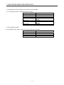
1.4 Combinations of servo amplifiers, servo motors, and controllers
1.4.1 Combinations of servo amplifiers and servo motors
Servo amplifier
MR-JE-10B
MR-JE-20B
MR-JE-40B
MR-JE-70B
Servo motor
HG-KN13_
HG-KN23_
HG-KN43_
HG-KN73_
HG-SN52_
HG-SN102_
HG-SN152_
HG-SN202_
HG-SN302_
MR-JE-100B
MR-JE-200B
MR-JE-300B
1.4.2 Compatible controller
For the simple motion module, refer to the user's manual of each series.
Series
Simple motion module
MELSEC iQ-R series
MELSEC-Q series
MELSEC-L series
MELSEC iQ-F series
1- 5
RD77MS_
QD77MS_
LD77MS_
FX5-40SSC-S
1. FUNCTIONS AND CONFIGURATION
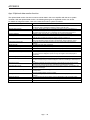
1.5 Function list
The following table lists the functions of this servo. For details of the functions, refer to each section
indicated in the detailed explanation field.
Function
Model adaptive control
Position control mode
Speed control mode
Torque control mode
High-resolution encoder
Absolute position detection
system
Gain switching function
Advanced vibration
suppression control II
Machine resonance
suppression filter
Shaft resonance suppression
filter
Adaptive filter II
Low-pass filter
Machine analyzer function
Robust filter
Slight vibration suppression
control
Auto tuning
Regenerative option
Alarm history clear
Output signal selection
(device settings)
Output signal (DO) forced
output
Test operation mode
MR Configurator2
One-touch tuning
Tough drive function
Description
This function realizes a high response and stable control following the ideal model.
The two-degrees-of-freedom model adaptive control enables you to set a response to
the command and response to the disturbance separately.
Additionally, this function can be disabled. Refer to section 7.4 to disable this function.
This servo amplifier is used as a position control servo.
This servo amplifier is used as a speed control servo.
This servo amplifier is used as a torque control servo.
A high-resolution encoder of 131072 pulses/rev is used as the encoder of the rotary
servo motor compatible with the MELSERVO-JE series.
Setting a home position once makes home position return unnecessary at every
power-on.
You can switch gains during rotation and during stop, and can use input devices to
switch gains during operation.
This function suppresses vibration at the arm end or residual vibration.
This filter function (notch filter) decreases the gain of the specific frequency to
suppress the resonance of the mechanical system.
When a load is mounted to the servo motor shaft, resonance by shaft torsion during
driving may generate a mechanical vibration at high frequency. The shaft resonance
suppression filter suppresses the vibration.
The servo amplifier detects mechanical resonance and sets filter characteristics
automatically to suppress mechanical vibration.
This function suppresses high-frequency resonance which occurs as servo system
response is increased.
This function analyzes the frequency characteristic of the mechanical system by
simply connecting an MR Configurator2 installed personal computer and servo
amplifier.
MR Configurator2 is necessary for this function.
This function enhances the disturbance response when the response level remains
low because the load to motor inertia ratio of axes, such as a roll feed axis, is high.
This function suppresses vibration of ±1 pulse generated at a servo motor stop.
This function automatically adjusts the gain to an optimum value if load applied to the
servo motor shaft varies.
Used when the built-in regenerative resistor of the servo amplifier does not have
sufficient regenerative capability for the regenerative power generated.
This function clears the alarm history.
The output devices including MBR (Electromagnetic brake interlock) and ALM
(Malfunction) can be assigned to certain pins of the CN3 connector.
Output signal can be forced on/off independently of the servo status.
Use this function for checking output signal wiring, etc.
Jog operation, positioning operation, motor-less operation, DO forced output, and
program operation
MR Configurator2 is necessary for this function.
Using a personal computer, you can perform the parameter setting, test operation,
monitoring, and others.
Gain adjustment is performed just by one click on a certain button on MR
Configurator2.
MR Configurator2 is necessary for this function.
This function makes the equipment continue operating even under the condition that
an alarm occurs.
The tough drive function includes two types: the vibration tough drive and the
instantaneous power failure tough drive.
1- 6
Detailed
explanation
Chapter 12
Section 7.2
Section 7.1.5
Section 7.1.1
Section 7.1.3
Section 7.1.2
Section 7.1.4
[Pr. PE41]
[Pr. PB24]
Section 6.3
Section 11.2
[Pr. PC21]
[Pr. PD07]
Section 4.5.1
(1) (d)
Section 4.5
Section 11.4
Section 6.2
Section 7.3
1. FUNCTIONS AND CONFIGURATION
Function
Drive recorder function
Servo amplifier life diagnosis
function
Power monitoring function
Machine diagnosis function
Continuous operation to
torque control mode
Lost motion compensation
function
Hot line forced stop function
Description
This function continuously monitors the servo status and records the status transition
before and after an alarm for a fixed period of time. You can check the recorded data
on the drive recorder window on MR Configurator2 by clicking the "Graph" button.
However, the drive recorder will not operate on the following conditions.
1. You are using the graph function of MR Configurator2.
2. You are using the machine analyzer function.
3. [Pr. PF21] is set to "-1".
4. The controller is not connected (except the test operation mode).
5. An alarm related to the controller is occurring.
You can check the cumulative energization time and the number of on/off times of the
inrush relay. This function gives an indication of the replacement time for parts of the
servo amplifier including a capacitor and a relay before they malfunction.
MR Configurator2 is necessary for this function.
This function calculates the power running energy and the regenerative power from
the data in the servo amplifier such as speed and current. Power consumption and
others are displayed on MR Configurator2. Since the servo amplifier sends data to a
servo system controller, you can analyze the data and display the data on a display
with the SSCNET III/H system.
From the data in the servo amplifier, this function estimates the friction and vibrational
component of the drive system in the equipment and recognizes an error in the
machine parts, including a ball screw and bearing.
MR Configurator2 is necessary for this function.
This function allows smooth switching of the mode from the position control mode or
speed control mode to the torque control mode without stopping. This function
eliminates rapid change of speed and torque, contributing to reduction in load to the
machine and high-quality product molding. For details of the continuous operation to
torque control mode, refer to the manuals for servo system controllers.
This function corrects response delays caused when the machine travel direction is
reversed.
This function enables all the normally operating MR-JE-_B servo amplifiers to
decelerate to a stop by transmitting hot line forced stop signals via the controller if an
alarm occurs in the MR-JE-_B servo amplifier.
1- 7
Detailed
explanation
[Pr. PA23]
[Pr. PB03]
Manuals of
servo system
controllers
Section 7.5
Section 3.7.3
1. FUNCTIONS AND CONFIGURATION
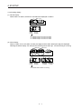
1.6 Model designation
(1) Rating plate
The following shows an example of the rating plate for explanation of each item.
AC SERVO
SER. A4Y001001
MR-JE-10B
POWER : 100W
INPUT : 3AC/200-240V 0.9A/1.5A 50/60Hz
OUTPUT : 3PH170V 0-360Hz 1.1A
STD.: IEC/EN61800-5-1 MAN.: IB(NA)0300194
Max. Surrounding Air Temp.: 55°C
IP20
MSIP-REI-MEK- TC300A982G51
DATE: 2014-11
TOKYO 100-8310, JAPAN
MADE IN JAPAN
(2) Model
The following describes what each block of a model name indicates.
SSCNETIII/H interface
Series
Rated output
Symbol Rated output [kW]
10
0.1
20
0.2
40
0.4
70
0.75
100
1
200
2
300
3
1- 8
Serial number
Model
Capacity
Applicable power supply
Rated output current
Standard, Manual number
Ambient temperature
IP rating
KC certification number
The year and month of manufacture
Country of origin
1. FUNCTIONS AND CONFIGURATION
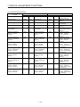
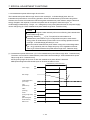
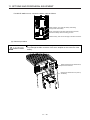
1.7 Structure
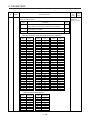
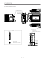
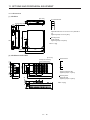
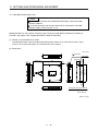
1.7.1 Parts identification
(1) MR-JE-100B or less
Detailed
explanation
No.
Name/Application
(1)
(1)
Display
The 3-digit, 7-segment LED shows the servo status and the
alarm number.
(2)
(2)
Axis selection rotary switch (SW1)
Used to set the axis number of the servo amplifier.
(3)
USB communication connector (CN5)
Used to connect this connector to a personal computer.
Section
11.4
I/O signal connector (CN3)
Used to connect digital I/O signals.
Section
3.2
Section
3.4
(3)
(4)
(5)
(9)
(4)
Side
(5)
Battery connector (CN4)
Used to connect the battery for absolute position data
backup.
(6)
Battery holder
Used to house the battery for absolute position data
backup.
(7)
SSCNET III cable connector (CN1A)
Used to connect the servo system controller or the previous
axis servo amplifier.
(8)
SSCNET III cable connector (CN1B)
Used to connect the next axis servo amplifier. For the final
axis, put a cap.
(7)
(6)
(8)
(9)
(10)
(10)
(11)
(12)
(12)
(11)
(13)
(13)
1- 9
Section
4.3
Chapter
12
Section
3.2
Section
3.4
Rating plate
Section
1.6
Encoder connector (CN2)
Used to connect the servo motor encoder.
Section
3.4
Power connector (CNP1)
Used to connect the input power supply, built-in
regenerative resistor, regenerative option, and servo motor.
Section
3.1
Section
3.3
Charge lamp
When the main circuit is charged, this lamp will light up.
While this lamp is lit, do not reconnect the cables.
Protective earth (PE) terminal
Grounding terminal
Section
3.1
Section
3.3
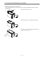
1. FUNCTIONS AND CONFIGURATION
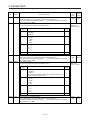
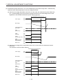
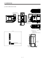
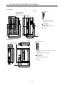
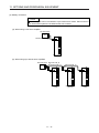
(2) MR-JE-200B or more
(1)
(2)
(3)
Name/Application
(1)
Display
The 3-digit, 7-segment LED shows the servo status and the
alarm number.
(2)
Axis selection rotary switch (SW1)
Used to set the axis number of the servo amplifier.
(3)
USB communication connector (CN5)
Used to connect this connector to a personal computer.
Section
11.4
I/O signal connector (CN3)
Used to connect digital I/O signals.
Section
3.2
Section
3.4
Power connector (CNP1)
Used to connect the input power supply and regenerative
option.
Section
3.1
Section
3.3
Rating plate
Section
1.6
(4)
(5)
(4)
(9)
(6)
Side
(5)
(6)
(10)
(7)
(7)
Battery holder
Used to house the battery for absolute position data
backup.
(11)
(13)
(8)
Battery connector (CN4)
Used to connect the battery for absolute position data
backup.
(12)
(8)
(9)
SSCNET III cable connector (CN1A)
Used to connect the servo system controller or the previous
axis servo amplifier.
(10)
SSCNET III cable connector (CN1B)
Used to connect the next axis servo amplifier. For the final
axis, put a cap.
(14)
Detailed
explanation
No.
(11)
Servo motor power connector (CNP2)
Used to connect the servo motor.
Section
4.3
Chapter
12
Section
3.2
Section
3.4
Section
3.1
Section
3.3
(12)
Charge lamp
When the main circuit is charged, this lamp will light up.
While this lamp is lit, do not reconnect the cables.
(13)
Encoder connector (CN2)
Used to connect the servo motor encoder.
Section
3.4
Protective earth (PE) terminal
Grounding terminal
Section
3.1
Section
3.3
(14)
1 - 10
1. FUNCTIONS AND CONFIGURATION
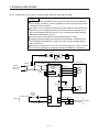
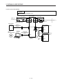
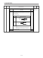
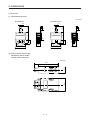
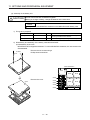
1.8 Configuration including peripheral equipment
CAUTION
Connecting a servo motor of the wrong axis to U, V, W, or CN2 of the servo
amplifier may cause a malfunction.
POINT
Equipment other than the servo amplifier and servo motor are optional or
recommended products.
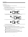
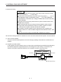
(1) MR-JE-100B or less
The diagram shows MR-JE-40B.
Personal
computer
CN5
MR Configurator2
RS T
(Note 1)
Power supply
Molded-case
circuit breaker
(MCCB)
CN3
(Note 2)
Magnetic
contactor
(MC)
Power factor
improving AC
reactor (FR-HAL)
Junction terminal
block
CN1A
Servo system controller or
previous servo amplifier
CN1B
CN1B
Next servo amplifier CN1A or
cap
Line noise filter
(FR-BSF01)
CN2
CN4
Battery
L1
L2
L3
U
Servo motor
V
W
Note 1. For 1-phase 200 V AC to 240 V AC, connect the power supply to L1 and L3. Leave L2 open. For the power supply
specifications, refer to section 1.3.
2. Depending on the power supply voltage and operation pattern, bus voltage can decrease. This can shift the mode to the
dynamic brake deceleration during forced stop deceleration. When dynamic brake deceleration is not required, slow the time to
turn off the magnetic contactor.
1 - 11
1. FUNCTIONS AND CONFIGURATION
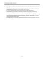
(2) MR-JE-200B or more
The diagram shows MR-JE-200B.
RS T
(Note 1)
Power supply
Molded-case
circuit breaker
(MCCB)
Personal
computer
(Note 2)
Magnetic
contactor
(MC)
CN5
MR Configurator2
Power factor
improving AC
reactor (FR-HAL)
CN3
Junction terminal
block
Line noise filter
(FR-BSF01)
CN1A
Servo system controller or
previous servo amplifier
CN1B
CN1B
Next servo amplifier CN1A or
cap
L1
L2
L3
U
V
W
CN2
CN4
Battery
Servo motor
Note 1. A 1-phase 200 V AC to 240 V AC power supply may be used with the servo amplifier of MR-JE-200B. For 1-phase 200 V AC
to 240 V AC, connect the power supply to L1 and L2. Leave L3 open. For the power supply specifications, refer to section 1.3.
2. Depending on the power supply voltage and operation pattern, bus voltage can decrease. This can shift the mode to the
dynamic brake deceleration during forced stop deceleration. When dynamic brake deceleration is not required, slow the time to
turn off the magnetic contactor.
1 - 12
2. INSTALLATION
2. INSTALLATION
WARNING
To prevent electric shock, ground each equipment securely.
CAUTION
Stacking in excess of the specified number of product packages is not allowed.
Do not hold the lead wire of the built-in regenerative resistor when transporting
the servo amplifier.
Install the equipment on incombustible material. Installing them directly or close to
combustibles will lead to a fire.
Install the servo amplifier and the servo motor in a load-bearing place in
accordance with the Instruction Manual.
Do not get on or put heavy load on the equipment. Otherwise, it may cause injury.
Use the equipment within the specified environment. For the environment, refer to
section 1.3.
Provide an adequate protection to prevent screws and other conductive matter, oil
and other combustible matter from entering the servo amplifier.
Do not block the intake and exhaust areas of the servo amplifier. Otherwise, it
may cause a malfunction.
Do not drop or strike the servo amplifier. Isolate it from all impact loads.
Do not install or operate the servo amplifier which has been damaged or has any
parts missing.
When the product has been stored for an extended period of time, contact your
local sales office.
When handling the servo amplifier, be careful about the edged parts such as
corners of the servo amplifier.
The servo amplifier must be installed in a metal cabinet.
When fumigants that contain halogen materials, such as fluorine, chlorine,
bromine, and iodine, are used for disinfecting and protecting wooden packaging
from insects, they cause malfunction when entering our products. Please take
necessary precautions to ensure that remaining materials from fumigant do not
enter our products, or treat packaging with methods other than fumigation, such
as heat treatment. Additionally, disinfect and protect wood from insects before
packing the products.
2- 1
2. INSTALLATION
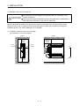
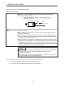
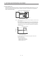
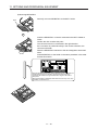
2.1 Installation direction and clearances
CAUTION
The equipment must be installed in the specified direction. Otherwise, it may
cause a malfunction.
Leave specified clearances between the servo amplifier and the cabinet walls or
other equipment. Otherwise, it may cause a malfunction.
MR-JE-40B to MR-JE-100B have a regenerative resistor on their back face. The regenerative resistor
generates heat of 100 °C higher than the ambient temperature. Please fully consider heat dissipation,
installation position, etc. when installing the servo amplifier.
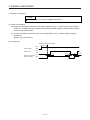
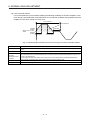
(1) Installation clearances of the servo amplifier
(a) Installation of one servo amplifier
Cabinet
Cabinet
40 mm
or more
Servo
amplifier
10 mm
or more
Wiring
allowance
80 mm
or more
10 mm
or more
Top
Bottom
40 mm
or more
2- 2
2. INSTALLATION
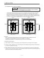
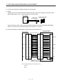
(b) Installation of two or more servo amplifiers
POINT
Close mounting is possible depending on the capacity of the servo amplifier.
Refer to section 1.3 for availability of close mounting.
Leave a large clearance between the top of the servo amplifier and the cabinet walls, and install a
cooling fan to prevent the internal temperature of the cabinet from exceeding the environment.
When mounting the servo amplifiers closely, leave a clearance of 1 mm between the adjacent servo
amplifiers in consideration of mounting tolerances. In this case, keep the ambient temperature within
0 ˚C to 45 ˚C or use the servo amplifier with 75% or lower of the effective load ratio.
Cabinet
Cabinet
100 mm or more
100 mm or more
10 mm or more
30 mm
or more
1 mm
1 mm
30 mm
or more
30 mm Top
or more
Bottom
40 mm or more
40 mm or more
Leaving clearance
Mounting closely
(2) Others
When using heat generating equipment such as the regenerative option, install them with full
consideration of heat generation so that the servo amplifier is not affected.
Install the servo amplifier on a perpendicular wall in the correct vertical direction.
2.2 Keep out foreign materials
(1) When drilling the cabinet, prevent drill chips and wire fragments from entering the servo amplifier.
(2) Prevent oil, water, metallic dust, etc. from entering the servo amplifier through openings in the cabinet or
a cooling fan installed on the ceiling.
(3) When installing the cabinet in a place where toxic gas, dirt, and dust exist, conduct an air purge (force
clean air into the cabinet from outside to make the internal pressure higher than the external pressure) to
prevent such materials from entering the cabinet.
2- 3
2. INSTALLATION
2.3 Encoder cable stress
(1) The way of clamping the cable must be fully examined so that bending stress and cable's own weight
stress are not applied to the cable connection.
(2) For use in any application where the servo motor moves, fix the cables (encoder, power supply, and
brake) with having some slack from the connector connection part of the servo motor to avoid putting
stress on the connector connection part. Use the optional encoder cable within the bending life range.
Use the power supply and brake wiring cables within the bending life of the cables.
(3) Avoid any probability that the cable sheath might be cut by sharp chips, rubbed by a machine corner, or
stamped by workers or vehicles.
(4) For installation on a machine where the servo motor moves, the flexing radius should be made as large
as possible. Refer to section 10.4 for the bending life.
2.4 SSCNET III cable laying
The SSCNET III cable is made from optical fiber. If power such as a major shock, lateral pressure, haul,
sudden bending, or twist is applied to the optical fiber, its inside distorts or breaks, and optical transmission
will not be available. Especially, as the optical fiber for MR-J3BUS_M/MR-J3BUS_M-A is made of synthetic
resin, it melts down if being left near the fire or high temperature. Therefore, do not make it touch the part
that can become hot such as heat sink or regenerative option of the servo amplifier.
Read described item of this section carefully and handle the SSCNET III cable with caution.
(1) Minimum bending radius
Make sure to lay the cable with greater radius than the minimum bending radius. Do not press the cable
to edges of equipment or others. For the SSCNET III cable, the appropriate length should be selected
with due consideration for the dimensions and arrangement of the servo amplifier. When closing the
door of the cabinet, pay careful attention to avoid the case that the SSCNET III cable is held down by the
door and the cable bend becomes smaller than the minimum bending radius. For the minimum bending
radius, refer to section 11.1.2.
(2) Prohibition of vinyl tape use
Migrating plasticizer is used for vinyl tape. Keep the MR-J3BUS_M, and MR-J3BUS_M-A cables away
from vinyl tape because the optical characteristic may be affected.
SSCNET III cable
Cord
Cable
MR-J3BUS_M
MR-J3BUS_M-A
MR-J3BUS_M-B
Optical cord
Cable
2- 4
: Phthalate ester plasticizer such as DBP and DOP
may affect optical characteristic of the cable.
: The cord and cable are not basically affected by
plasticizer.
2. INSTALLATION
(3) Precautions for migrating plasticizer added materials
Generally, soft polyvinyl chloride (PVC), polyethylene resin (PE), and fluorine resin contain nonmigrating plasticizer and they do not affect the optical characteristic of the SSCNET III cable. However,
some wire sheaths and cable ties that contain migrating plasticizer (phthalate ester) may affect MRJ3BUS_M and MR-J3BUS_M-A cables (plastic).
In addition, the MR-J3BUS_M-B cable (silica glass) is not affected by plasticizer.
A chemical substance may affect its optical characteristic. Therefore, previously check that the cable is
not affected by the environment.
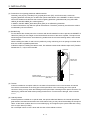
(4) Bundle fixing
Fix the cable at the closest part to the connector with bundle material in order to prevent the SSCNET III
cable from putting its own weight on the CN1A/CN1B connector of the servo amplifier. The optical cord
should be given loose slack to avoid becoming smaller than the minimum bending radius, and it should
not be twisted.
When bundling the cable, fix and hold it in position by using cushioning such as sponge or rubber which
does not contain migratable plasticizers.
If adhesive tape for bundling the cable is used, fire resistant acetate cloth adhesive tape 570F (Teraoka
Seisakusho Co., Ltd) is recommended.
Connector
Optical cord
Loose slack
Bundle material
Recommended product: NK clamp SP type
(NIX, INC)
Cable
(5) Tension
If tension is added on an optical cable, the increase of transmission loss occurs because of external
force which concentrates on the fixing part of the optical fiber or the connecting part of the optical
connector. Doing so may cause the breakage of the optical fiber or damage of the optical connector. For
cable laying, handle the cable without putting forced tension. For the tension strength, refer to section
11.1.2.
(6) Lateral pressure
If lateral pressure is added on an optical cable, the optical cable itself distorts, the internal optical fiber
gets stressed, and then transmission loss will increase. Doing so may cause the breakage of the optical
cable. As the same condition also occurs at cable laying, do not tighten up the optical cable with a thing
such as nylon band (TY-RAP).
Do not trample it down or tuck it down with the door of the cabinet or others.
2- 5
2. INSTALLATION
(7) Twisting
If optical fiber is twisted, it will become the same stress added condition as when local lateral pressure or
bend is added. Consequently, transmission loss increases, and the breakage of the optical fiber may
occur.
(8) Disposal
When the optical cable (cord) used for an SSCNET III cable, hydrogen fluoride gas or hydrogen chloride
gas which is corrosive and harmful may be generated. For disposal of optical fiber, request for
specialized industrial waste disposal services who has incineration facility for disposing hydrogen
fluoride gas or hydrogen chloride gas.
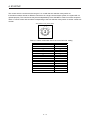
2.5 Inspection items
WARNING
Before starting maintenance and/or inspection, turn off the power and wait for 15
minutes or more until the charge lamp turns off. Otherwise, an electric shock may
occur. In addition, when confirming whether the charge lamp is off or not, always
confirm it from the front of the servo amplifier.
To avoid an electric shock, only qualified personnel should attempt inspections.
For repair and parts replacement, contact your local sales office.
CAUTION
Do not perform insulation resistance test on the servo amplifier. Otherwise, it may
cause a malfunction.
Do not disassemble and/or repair the equipment on customer side.
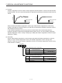
It is recommended that the following points periodically be checked.
(1) Check for loose terminal block screws. Retighten any loose screws.
(2) Check for scratches and cracks of cables and the like. Inspect them periodically according to operating
conditions especially when the servo motor is movable.
(3) Check that the connector is securely connected to the servo amplifier.
(4) Check that the wires are not coming out from the connector.
(5) Check for dust accumulation on the servo amplifier.
(6) Check for unusual noise generated from the servo amplifier.
2- 6
2. INSTALLATION
2.6 Parts having service lives
Service lives of the following parts are listed below. However, the service life varies depending on operating
methods and environment. If any fault is found in the parts, they must be replaced immediately regardless of
their service lives. For parts replacement, please contact your local sales office.
Part name
Life guideline
Smoothing capacitor
Relay
Cooling fan
Absolute position battery
10 years
Number of power-on, forced stop by EM1
(Forced stop 1), and controller forced stop
times: 100 000 times
50,000 hours to 70,000 hours
(7 years to 8 years)
Refer to section 12.2.
(1) Smoothing capacitor
The characteristic of a smoothing capacitor is deteriorated due to ripple currents, etc. The life of the
capacitor greatly depends on ambient temperature and operating conditions. The capacitor will reach
the end of its life in 10 years of continuous operation in normal air-conditioned environment (40 ˚C
surrounding air temperature or lower).
(2) Relays
Contact faults will occur due to contact wear arisen from switching currents. Relays will reach the end of
their lives depending on their power supply capacity when the number of power-on times, number of
forced stop times by EM1 (Forced stop 1), and number of controller forced stop times are 100,000 times
in total.
(3) Servo amplifier cooling fan
The cooling fan bearings reach the end of their lives in 50,000 hours to 70,000 hours. Normally,
therefore, the cooling fan must be replaced in a few years of continuous operation as a guideline. It must
also be changed if unusual noise or vibration is found during inspection.
The life indicates under the yearly average ambient temperature of 40 ˚C, free from corrosive gas,
flammable gas, oil mist, dust, and dirt.
2- 7
2. INSTALLATION
MEMO
2- 8
3. SIGNALS AND WIRING
3. SIGNALS AND WIRING
WARNING
Any person who is involved in wiring should be fully competent to do the work.
Before wiring, turn off the power and wait for 15 minutes or more until the charge
lamp turns off. Otherwise, an electric shock may occur. In addition, when
confirming whether the charge lamp is off or not, always confirm it from the front
of the servo amplifier.
Ground the servo amplifier and servo motor securely.
Do not attempt to wire the servo amplifier and servo motor until they have been
installed. Otherwise, it may cause an electric shock.
The cables should not be damaged, stressed, loaded, or pinched. Otherwise, it
may cause an electric shock.
To avoid an electric shock, insulate the connections of the power supply
terminals.
Before removing the CNP1 connector from MR-JE-40B to MR-JE-100B,
disconnect the lead wires of the regenerative resistor from the CNP1 connector.
Wire the equipment correctly and securely. Otherwise, the servo motor may
operate unexpectedly, resulting in injury.
Connect cables to the correct terminals. Otherwise, a burst, damage, etc. may
occur.
Ensure that polarity (+/-) is correct. Otherwise, a burst, damage, etc. may occur.
The surge absorbing diode installed to the DC relay for control output should be
fitted in the specified direction. Otherwise, the emergency stop and other
protective circuits may not operate.
Servo amplifier
24 V DC
DOCOM
CAUTION
Control output
signal
For sink output interface
Servo amplifier
24 V DC
DOCOM
RA
Control output
signal
RA
For source output interface
Use a noise filter, etc. to minimize the influence of electromagnetic interference.
Electromagnetic interference may be given to the electronic equipment used near
the servo amplifier.
Do not install a power capacitor, surge killer, or radio noise filter (optional FR-BIF)
with the power line of the servo motor.
When using a regenerative resistor, switch power off with the alarm signal.
Otherwise, a transistor fault or the like may overheat the regenerative resistor,
causing a fire.
Do not modify the equipment.
3- 1
3. SIGNALS AND WIRING
Connect the servo amplifier power output (U, V, and W) to the servo motor power
input (U, V, and W) directly. Do not let a magnetic contactor, etc. intervene.
Otherwise, it may cause a malfunction.
Servo amplifier
U
CAUTION
V
W
U
Servo motor
V
W
Servo amplifier
U
M
V
W
U
Servo motor
V
M
W
Connecting a servo motor of the wrong axis to U, V, W, or CN2 of the servo
amplifier may cause a malfunction.
3.1 Input power supply circuit
CAUTION
Always connect a magnetic contactor between the power supply and the power
supply (L1, L2, and L3) of the servo amplifier, in order to configure a circuit that
shuts down the power supply on the side of the servo amplifier’s power supply. If
a magnetic contactor is not connected, continuous flow of a large current may
cause a fire when the servo amplifier malfunctions.
Use an alarm to switch power off. Not doing so may cause a fire when a
regenerative transistor malfunction or the like may overheat the regenerative
resistor.
Before removing the CNP1 connector from MR-JE-40B to MR-JE-100B,
disconnect the lead wires of the regenerative resistor from the CNP1 connector.
Not doing so may break the lead wires of the regenerative resistor.
Check the servo amplifier model, and then input proper voltage to the servo
amplifier power supply. If input voltage exceeds the upper limit of the
specification, the servo amplifier will break down.
The servo amplifier has a built-in surge absorber (varistor) to reduce noise and to
suppress lightning surge. The varistor can break down due to its aged
deterioration. To prevent a fire, use a molded-case circuit breaker or fuse for input
power supply.
Connecting a servo motor of the wrong axis to U, V, W, or CN2 of the servo
amplifier may cause a malfunction.
N- terminal is not a neutral point of the power supply. Incorrect wiring may cause
a burst, damage, etc.
POINT
EM2 has the same function as EM1 in the torque control mode.
When a 1-phase 200 V AC to 240 V AC power supply is used, the connection
destination differs depending on the servo amplifier. Ensure that the connection
destination is correct.
Configure the wiring so that the power supply is shut off and the servo-on command is turned off after
deceleration to a stop due to an alarm occurring, an enabled servo forced stop, or an enabled controller
forced stop. A molded-case circuit breaker (MCCB) must be used with the input cables of the power supply.
3- 2
3. SIGNALS AND WIRING
(1) For 3-phase 200 V AC to 240 V AC power supply of MR-JE-10B to MR-JE-100B
POINT
For MR-JE-_B servo amplifiers, the hot line forced stop function is enabled at
factory setting. For MR-J4-_B servo amplifiers, the hot line forced stop function
is disabled at factory setting.
If an alarm occurs, the hot line forced stop function outputs hot line forced stop
signals to all servo amplifiers before a communication to the controller is cut.
Then, servo amplifiers will be in the [AL. E7.1 Controller forced stop warning]
state and will decelerate to a stop.
The hot line forced stop function can be disabled with [Pr. PA27].
Configure the power supply circuit which turns off magnetic contactors of all
servo amplifiers after detection of alarm occurrence on the controller side at
alarm occurrence.
OFF
ON
Emergency stop switch
MC
MC
SK
(Note 5)
Alarm
MCCB
MC (Note 8)
3-phase
200 V AC to
240 V AC
(Note 1)
Servo amplifier
CNP1
L1
Built-in
L2 regenerative U
V
L3 resistor
P+
Servo motor
(Note 4, 7)
U
V
W
W
Motor
M
C
(Note 7)
CN2
Forced stop 2
(Note 6)
Power
supply
(Note 2)
Encoder cable
Encoder
CN3
EM2
(Note 3)
CN3
24 V DC (Note 9)
DOCOM
DICOM
24 V DC (Note 9)
3- 3
MBR
RA1
Electromagnetic
brake interlock
(Note 3)
3. SIGNALS AND WIRING
Note 1. MR-JE-40B to MR-JE-100B have a built-in regenerative resistor. (factory-wired) When using the regenerative option, refer to
section 11.2.
2. For the encoder cable, use of the option cable is recommended. For cable selection, refer to "HG-KN_/HG-SN_ Servo Motor
Instruction Manual".
3. This diagram is for the sink I/O interface. For source I/O interface, refer to section 3.8.3.
4. For connection of servo motor power wires, refer to "HG-KN_/HG-SN_ Servo Motor Instruction Manual".
5. Configure the power supply circuit that turns off the magnetic contactor after an alarm occurs on the controller side.
6. Configure a circuit to turn off EM2 when the power is turned off to prevent an unexpected restart of the servo amplifier.
7. Connecting a servo motor of the wrong axis to U, V, W, or CN2 of the servo amplifier may cause a malfunction.
8. Use a magnetic contactor with an operation delay time (interval since a current is applied to the coil until the contact closes) of
80 ms or shorter. Depending on the power supply voltage and operation pattern, bus voltage can decrease. This can shift the
mode to the dynamic brake deceleration during forced stop deceleration. When dynamic brake deceleration is not required,
slow the time to turn off the magnetic contactor.
9. The illustration of the 24 V DC power supply is divided between input signal and output signal for convenience. However, they
can be configured by one.
3- 4
3. SIGNALS AND WIRING
(2) For 1-phase 200 V AC to 240 V AC power supply of MR-JE-10B to MR-JE-100B
POINT
For MR-JE-_B servo amplifiers, the hot line forced stop function is enabled at
factory setting. For MR-J4-_B servo amplifiers, the hot line forced stop function
is disabled at factory setting.
If an alarm occurs, the hot line forced stop function outputs hot line forced stop
signals to all servo amplifiers before a communication to the controller is cut.
Then, servo amplifiers will be in the [AL. E7.1 Controller forced stop warning]
state and will decelerate to a stop.
The hot line forced stop function can be disabled with [Pr. PA27].
Configure the power supply circuit which turns off magnetic contactors of all
servo amplifiers after detection of alarm occurrence on the controller side at
alarm occurrence.
Connect the 1-phase 200 V AC to 240 V AC power supply to L1 and L3. One of
the connecting destinations is different from MR-JE-200B Servo Amplifier's.
OFF
ON
Emergency stop switch
MC
MC
SK
(Note 5)
Alarm
MCCB
MC (Note 8)
1-phase
200 V AC to
240 V AC
(Note 1)
Servo amplifier
CNP1
L1
Built-in
L2 regenerative U
V
L3 resistor
P+
Servo motor
(Note 4, 7)
U
V
W
W
Motor
M
C
(Note 7)
CN2
Forced stop 2
(Note 6)
Power
supply
(Note 2)
Encoder cable
Encoder
CN3
EM2
(Note 3)
CN3
24 V DC (Note 9)
DOCOM
DICOM
24 V DC (Note 9)
3- 5
MBR
RA1
Electromagnetic
brake interlock
(Note 3)
3. SIGNALS AND WIRING
Note 1. MR-JE-40B to MR-JE-100B have a built-in regenerative resistor. (factory-wired) When using the regenerative option, refer to
section 11.2.
2. For the encoder cable, use of the option cable is recommended. For cable selection, refer to "HG-KN_/HG-SN_ Servo Motor
Instruction Manual".
3. This diagram is for the sink I/O interface. For source I/O interface, refer to section 3.8.3.
4. For connection of servo motor power wires, refer to "HG-KN_/HG-SN_ Servo Motor Instruction Manual".
5. Configure the power supply circuit that turns off the magnetic contactor after an alarm occurs on the controller side.
6. Configure a circuit to turn off EM2 when the power is turned off to prevent an unexpected restart of the servo amplifier.
7. Connecting a servo motor of the wrong axis to U, V, W, or CN2 of the servo amplifier may cause a malfunction.
8. Use a magnetic contactor with an operation delay time (interval since a current is applied to the coil until the contact closes) of
80 ms or shorter. Depending on the power supply voltage and operation pattern, bus voltage can decrease. This can shift the
mode to the dynamic brake deceleration during forced stop deceleration. When dynamic brake deceleration is not required,
slow the time to turn off the magnetic contactor.
9. The illustration of the 24 V DC power supply is divided between input signal and output signal for convenience. However, they
can be configured by one.
3- 6
3. SIGNALS AND WIRING
(3) For 3-phase 200 V AC to 240 V AC power supply of MR-JE-200B or MR-JE-300B
POINT
For MR-JE-_B servo amplifiers, the hot line forced stop function is enabled at
factory setting. For MR-J4-_B servo amplifiers, the hot line forced stop function
is disabled at factory setting.
If an alarm occurs, the hot line forced stop function outputs hot line forced stop
signals to all servo amplifiers before a communication to the controller is cut.
Then, servo amplifiers will be in the [AL. E7.1 Controller forced stop warning]
state and will decelerate to a stop.
The hot line forced stop function can be disabled with [Pr. PA27].
Configure the power supply circuit which turns off magnetic contactors of all
servo amplifiers after detection of alarm occurrence on the controller side at
alarm occurrence.
OFF
ON
Emergency stop switch
MC
MC
SK
(Note 5)
Alarm
Servo amplifier
MC (Note 8)
MCCB
3-phase
200 V AC to
240 V AC
CNP1
L1
L2
Servo motor
CNP2
U
(Note 4, 7)
U
L3
V
V
N-
W
W
Motor
M
C
(Note 1)
D
P+
(Note 7)
CN2
(Note 6)
Power
supply
Forced stop 2
(Note 2)
Encoder cable
Encoder
CN3
EM2
(Note 3)
CN3
24 V DC (Note 9)
DOCOM
DICOM
24 V DC (Note 9)
3- 7
MBR
RA1
Electromagnetic
brake interlock
(Note 3)
3. SIGNALS AND WIRING
Note 1. Always connect between P+ and D terminals. (factory-wired) When using the regenerative option, refer to section 11.2.
2. For the encoder cable, use of the option cable is recommended. For cable selection, refer to "HG-KN_/HG-SN_ Servo Motor
Instruction Manual".
3. This diagram is for the sink I/O interface. For source I/O interface, refer to section 3.8.3.
4. For connection of servo motor power wires, refer to "HG-KN_/HG-SN_ Servo Motor Instruction Manual".
5. Configure the power supply circuit that turns off the magnetic contactor after an alarm occurs on the controller side.
6. Configure a circuit to turn off EM2 when the power is turned off to prevent an unexpected restart of the servo amplifier.
7. Connecting a servo motor of the wrong axis to U, V, W, or CN2 of the servo amplifier may cause a malfunction.
8. Use a magnetic contactor with an operation delay time (interval since a current is applied to the coil until the contact closes) of
80 ms or shorter. Depending on the power supply voltage and operation pattern, bus voltage can decrease. This can shift the
mode to the dynamic brake deceleration during forced stop deceleration. When dynamic brake deceleration is not required,
slow the time to turn off the magnetic contactor.
9. The illustration of the 24 V DC power supply is divided between input signal and output signal for convenience. However, they
can be configured by one.
3- 8
3. SIGNALS AND WIRING
(4) For 1-phase 200 V AC to 240 V AC power supply of MR-JE-200B
POINT
For MR-JE-_B servo amplifiers, the hot line forced stop function is enabled at
factory setting. For MR-J4-_B servo amplifiers, the hot line forced stop function
is disabled at factory setting.
If an alarm occurs, the hot line forced stop function outputs hot line forced stop
signals to all servo amplifiers before a communication to the controller is cut.
Then, servo amplifiers will be in the [AL. E7.1 Controller forced stop warning]
state and will decelerate to a stop.
The hot line forced stop function can be disabled with [Pr. PA27].
Configure the power supply circuit which turns off magnetic contactors of all
servo amplifiers after detection of alarm occurrence on the controller side at
alarm occurrence.
Connect the 1-phase 200 V AC to 240 V AC power supply to L1 and L2. One of
the connecting destinations is different from MR-JE-100B or less Servo
Amplifier's.
OFF
ON
Emergency stop switch
MC
MC
SK
(Note 5)
Alarm
1-phase
200 V AC to
240 V AC
MCCB
MC (Note 8)
Servo amplifier
CNP1
L1
CNP2
U
L2
Servo motor
(Note 4, 7)
U
L3
V
V
N-
W
W
Motor
M
C
(Note 1)
D
P+
(Note 7)
CN2
Forced stop 2
(Note 6)
Power
supply
(Note 2)
Encoder cable
Encoder
CN3
EM2
(Note 3)
CN3
24 V DC (Note 9)
DOCOM
DICOM
24 V DC (Note 9)
3- 9
MBR
RA1
Electromagnetic (Note 3)
brake interlock
3. SIGNALS AND WIRING
Note 1. Always connect between P+ and D terminals. (factory-wired) When using the regenerative option, refer to section 11.2.
2. For the encoder cable, use of the option cable is recommended. For cable selection, refer to "HG-KN_/HG-SN_ Servo Motor
Instruction Manual".
3. This diagram is for the sink I/O interface. For source I/O interface, refer to section 3.8.3.
4. For connection of servo motor power wires, refer to "HG-KN_/HG-SN_ Servo Motor Instruction Manual".
5. Configure the power supply circuit that turns off the magnetic contactor after an alarm occurs on the controller side.
6. Configure a circuit to turn off EM2 when the power is turned off to prevent an unexpected restart of the servo amplifier.
7. Connecting a servo motor of the wrong axis to U, V, W, or CN2 of the servo amplifier may cause a malfunction.
8. Use a magnetic contactor with an operation delay time (interval since a current is applied to the coil until the contact closes) of
80 ms or shorter. Depending on the power supply voltage and operation pattern, bus voltage can decrease. This can shift the
mode to the dynamic brake deceleration during forced stop deceleration. When dynamic brake deceleration is not required,
slow the time to turn off the magnetic contactor.
9. The illustration of the 24 V DC power supply is divided between input signal and output signal for convenience. However, they
can be configured by one.
3 - 10
3. SIGNALS AND WIRING
3.2 I/O signal connection example
POINT
EM2 has the same function as EM1 in the torque control mode.
3.2.1 For sink I/O interface
(Note 3, 4)
Forced stop 2
10 m or less
(Note 12)
Power supply
Servo amplifier
10 m or less
24 V DC (Note 10)
CN3
CN3
EM2
20
3
DOCOM
DICOM
10
13
MBR
(Note 2)
Electromagnetic brake
interlock
RA1
(Note 10) 24 V DC
Servo system
controller
(Note 11)
Servo amplifier
(Note 6)
SSCNET III cable
(option)
(Note 7)
CN1A
CN1A CN1B
(Note 1)
CN1B
(Note 5)
MR Configurator2
Personal
computer
USB cable
MR-J3USBCBL3M
(option)
The last servo amplifier (Note 8)
(Note 7)
CN5
+
CN1A
(Note 6)
SSCNET III cable
(option)
(Note 9)
Cap
CN1B
Note 1. To prevent an electric shock, always connect the protective earth (PE) terminal (marked with
) of the servo amplifier to the
protective earth (PE) of the cabinet.
2. Connect the diode in the correct direction. If it is connected reversely, the servo amplifier will malfunction and will not output
signals, disabling EM2 (Forced stop 2) and other protective circuits.
3. If the controller does not have a forced stop function, always install the forced stop 2 switch (normally closed contact).
4. When starting operation, always turn on EM2 (Forced stop 2). (normally closed contact)
5. Use SW1DNC-MRC2-_. (Refer to section 11.4.)
6. Use SSCNET III cables listed in the following table.
Cable
Standard cord inside
cabinet
Standard cable
outside cabinet
Long distance cable
Cable model
Cable length
MR-J3BUS_M
0.15 m to 3 m
MR-J3BUS_M-A
5 m to 20 m
MR-J3BUS_M-B
30 m to 50 m
7. The wiring after the second servo amplifier is omitted.
8. Up to 16 axes of servo amplifiers can be connected. The number of connectable axes depends on the controller you use.
Refer to section 4.3.1 for setting of axis selection.
9. Make sure to cap the unused CN1B connector.
10. Supply 24 V DC ± 10% to interfaces from outside. The total current capacity of these power supplies must be 100 mA or lower.
The current capacity 100 mA is applicable when all I/O signals are used. The current capacity can be decreased by reducing
the number of I/O points. Refer to section 3.8.2 that gives the current value necessary for the interface. The illustration of the
24 V DC power supply is divided between input signal and output signal for convenience. However, they can be configured by
one.
11. You can change a device assigned to the CN3-13 pin with [Pr. PD07].
12. Configure a circuit to turn off EM2 when the power is turned off to prevent an unexpected restart of the servo amplifier.
3 - 11
3. SIGNALS AND WIRING
3.2.2 For source I/O interface
POINT
For notes, refer to section 3.2.1.
(Note 3, 4)
Forced stop 2
10 m or less
(Note 12)
Power supply
Servo amplifier
10 m or less
24 V DC (Note 10)
CN3
CN3
EM2
20
3
DOCOM
DICOM
10
13
MBR
(Note 2)
RA1
(Note 10) 24 V DC
Servo system
controller
Electromagnetic brake (Note 11)
interlock
Servo amplifier
(Note 6)
SSCNET III cable
(option)
(Note 7)
CN1A
CN1A CN1B
(Note 1)
CN1B
(Note 5)
MR Configurator2
+
Personal
computer
USB cable
MR-J3USBCBL3M
(option)
CN5
The last servo amplifier (Note 8)
(Note 7)
CN1A
(Note 6)
SSCNET III cable
(option)
3 - 12
(Note 9)
Cap
CN1B
3. SIGNALS AND WIRING
3.3 Explanation of power supply system
3.3.1 Signal explanations
POINT
For the layout of the connector and terminal block, refer to chapter 9
DIMENSIONS.
Symbol
Connection
destination
(application)
Description
Supply the following power to L1, L2, and L3. For 1-phase 200 V AC to 240 V AC of MR-JE-10B to
MR-JE-100B, connect the power supply to L1 and L3. Leave L2 open.
For 1-phase 200 V AC to 240 V AC of MR-JE-200B, connect the power supply to L1 and L2. Leave
L3 open.
L1/L2/L3
Power supply
Servo amplifier
Power supply
3-phase 200 V AC to 240 V AC,
50 Hz/60 Hz
1-phase 200 V AC to 240 V AC,
50 Hz/60 Hz
P+/C/D
Regenerative
option
U/V/W
Servo motor
power output
NProtective earth
(PE)
MR-JE-10B to
MR-JE-100B
MR-JE-200B
MR-JE-300B
L1/L2/L3
L1/L3
L1/L2
1) MR-JE-100B or less
MR-JE-10B to MR-JE-100B do not have D.
When using a servo amplifier built-in regenerative resistor, connect it to P+ and C. (factorywired)
MR-JE-10B and MR-JE-20B do not have a built-in regenerative resistor.
When using a regenerative option, disconnect wires of the built-in regenerative resistor from P+
and C. Then, connect wires of the regenerative option to P+ and C.
2) MR-JE-200B or more
When using a servo amplifier built-in regenerative resistor, connect P+ and D. (factory-wired)
When using a regenerative option, disconnect P+ and D, and connect the regenerative option to
P+ and C.
Refer to section 11.2 for details.
Connect the terminals to the servo motor power supply terminals (U, V, and W). Connect the servo
amplifier power output (U, V, and W) to the servo motor power input (U, V, and W) directly. Do not
let a magnetic contactor, etc. intervene. Otherwise, it may cause a malfunction.
This terminal is for manufacturer adjustment.
Leave this terminal open.
MR-JE-10B to MR-JE-100B do not have N-.
Connect this terminal to the grounding terminal of the servo motor and to the protective earth (PE)
of the cabinet for grounding.
3 - 13
3. SIGNALS AND WIRING
3.3.2 Power-on sequence
POINT
The output signal, etc. may be unstable at power-on.
(1) Power-on procedure
(a) Always use a magnetic contactor for the power supply wiring (L1, L2, and L3) as shown in above
section 3.1. Configure the power supply circuit that turns off the magnetic contactor after an alarm
occurs on the controller side.
(b) The servo amplifier receives the servo-on command within 3 s to 4 s after the power supply is
switched on.
(Refer to (2) of this section.)
(2) Timing chart
Servo-on command accepted
(3 s to 4 s)
Power supply
Base circuit
ON
OFF
ON
OFF
95 ms
Servo-on command ON
(from controller)
OFF
3 - 14
10 ms
95 ms
3. SIGNALS AND WIRING
3.3.3 Wiring CNP1 and CNP2
POINT
For the wire sizes used for wiring, refer to section 11.6.
For the wiring to CNP1 and CNP2, use servo amplifier power connectors packed with the amplifier or
optional connectors (refer to section 11.1.1).
(1) Connector
(a) MR-JE-10B to MR-JE-100B
Servo amplifier
CNP1
Table 3.1 Connector and applicable wire
Connector
Receptacle assembly
CNP1
09JFAT-SAXGDK-H5.0
Applicable wire
Size
Insulator OD
Stripped
length [mm]
Open tool
Manufacturer
AWG 18 to 14
3.9 mm or shorter
9
J-FAT-OT
JST
(b) MR-JE-200B/MR-JE-300B
Servo amplifier
CNP1
CNP2
Table 3.2 Connector and applicable wire
Connector
Receptacle assembly
CNP1
07JFAT-SAXGFK-XL
CNP2
03JFAT-SAXGFK-XL
Applicable wire
Size
Insulator OD
Stripped
length [mm]
Open tool
Manufacturer
AWG 16 to 10
4.7 mm or shorter
11.5
J-FAT-OT-EXL
JST
3 - 15
3. SIGNALS AND WIRING
(2) Cable connection procedure
(a) Fabrication on cable insulator
Refer to table 3.1 and 3.2 for stripped length of the cable insulator. The appropriate stripped length
of cables depends on their type, etc. Set the length considering their status.
Insulator
Core
Stripped length
Twist strands lightly and straighten them as follows.
Loose and bent strands
Twist and straighten
the strands.
You can also use a ferrule for connection with the connectors. When using a ferrule, select a ferrule
and crimping tool listed in the table below.
Servo amplifier
Wire size
MR-JE-10B to
MR-JE-100B
AWG 16
AWG 14
AWG 16
AWG 14
AWG 12
MR-JE-200B to
MR-JE-300B
Ferrule model (Phoenix Contact)
For one
For two
AI1.5-10BK
AI2.5-10BU
AI1.5-10BK
AI2.5-10BU
AI4-10GY
Crimp terminal
(Phoenix Contact)
AI-TWIN2 × 1.5-10BK
AI-TWIN2 × 1.5-10BK
AI-TWIN2 × 2.5-10BU
CRIMPFOX-ZA3
(b) Inserting wire
Insert the open tool as follows and push down it to open the spring. While the open tool is pushed
down, insert the stripped wire into the wire insertion hole. Check the insertion depth so that the wire
insulator does not get caught by the spring.
Release the open tool to fix the wire. Pull the wire lightly to confirm that the wire is surely connected.
The following shows a connection example of the CNP2 connector for 2 kW and 3 kW.
1) Push down the open tool.
3) Release the open tool to fix the wire.
2) Insert the wire.
3 - 16
3. SIGNALS AND WIRING
3.4 Connectors and pin assignment
POINT
The pin assignment of the connectors is as viewed from the cable connector
wiring section.
For the CN3 connector, securely connect the external conductor of the shielded
cable to the ground plate and fix it to the connector shell.
Screw
Cable
Screw
Ground plate
The servo amplifier front view shown is that of the MR-JE-40B or less. Refer to chapter 9 DIMENSIONS for
the appearances and connector layouts of the other servo amplifiers.
CN5 (USB connector)
Refer to section 11.4.
CN3
CN4
(Battery connector)
Refer to section 11.5.
1
2
11
12
3
CN1A
Connector for SSCNET III
cable for previous servo
amplifier axis
CN1B
Connector for SSCNET III
cable for next servo
amplifier axis
CN2
2
LG
4
6
MRR
1
P5
3
MR
8
10
MDR
5
7
MD
9
BAT
4
DOCOM
5
15
17
7
18
19
9
3 - 17
MBR
16
6
8
The frames of the CN2 and CN3
connectors are connected to the
protective earth terminal in the
servo amplifier.
13
14
10
20
DICOM
EM2
3. SIGNALS AND WIRING
3.5 Signal (device) explanations
For the I/O interfaces (symbols in I/O division column in the table), refer to section 3.8.2.
The pin numbers in the connector pin number column are those in the initial status.
3.5.1 Input device
Device
Symbol
Connector
pin
number
I/O
division
Function and application
Turn off EM2 (open between commons) to decelerate the servo motor to a stop
with commands.
Turn EM2 on (short between commons) in the forced stop state to reset that
state.
Set [Pr. PA04] to "2 1 _ _" to disable EM2.
The following shows the setting of [Pr. PA04].
[Pr. PA04]
EM2/EM1
setting
Forced stop 2
Forced stop 1
EM2
EM1
00__
EM1
20__
EM2
01__
Not using
EM2 or
EM1
21__
Not using
EM2 or
EM1
CN3-20
Deceleration method
EM2 or EM1 is off
Alarm occurred
MBR (Electromagnetic
brake interlock) turns off
without the forced stop
deceleration.
MBR (Electromagnetic
brake interlock) turns off
after the forced stop
deceleration.
MBR (Electromagnetic
brake interlock) turns off
without the forced stop
deceleration.
MBR (Electromagnetic
brake interlock) turns off
after the forced stop
deceleration.
MBR (Electromagnetic
brake interlock) turns off
without the forced stop
deceleration.
MBR (Electromagnetic
brake interlock) turns off
after the forced stop
deceleration.
EM2 and EM1 are mutually exclusive.
Note that EM2 has the same function as EM1 in the torque control mode.
When using EM1, set [Pr. PA04] to "0 0 _ _" to enable EM1.
Turn EM1 off (open between commons) to bring the motor to a forced stop
state. The base circuit is shut off, and the dynamic brake is operated and
(CN3-20) decelerates the servo motor to a stop.
Turn EM1 on (short between commons) in the forced stop state to reset that
state.
Set [Pr. PA04] to "0 1 _ _" to disable EM1.
3 - 18
DI-1
DI-1
3. SIGNALS AND WIRING
3.5.2 Output device
(1) Output device pin
The following shows the output device pins and parameters for assigning devices.
Connector pin
number
Parameter
Initial device
I/O division
CN3-13
[Pr. PD07]
MBR
DO-1
(2) Output device explanations
Symbol
Function and application
Electromagnetic
brake interlock
Device
MBR
Malfunction
ALM
In-position
INP
Ready
Speed reached
RD
SA
Limiting speed
VLC
Zero speed detection
ZSP
When using the device, set operation delay time of the electromagnetic brake in [Pr. PC02].
When a servo-off status or alarm occurs, MBR will turn off.
When the protective circuit is activated to shut off the base circuit, ALM will turn off.
When an alarm does not occur, ALM will turn on after 2.5 s to 3.5 s after power-on.
When the number of droop pulses is in the in-position range, INP will turn on. The in-position range
can be changed using [Pr. PA10]. When the in-position range is increased, INP may be on during
low-speed rotation.
The device cannot be used in the speed control mode or torque control mode or for continuous
operation to torque control mode.
Enabling servo-on to make the servo amplifier ready to operate will turn on RD.
SA will turn off during servo-off. When the servo motor speed reaches the following range, SA will
turn on.
Preset speed ± ((Preset speed × 0.05) + 20) r/min
When the preset speed is 20 r/min or slower, SA always turns on.
The device cannot be used in the position control mode and torque control mode.
When the speed reaches the speed limit value in the torque control mode, VLC will turn on. When
the servo is off, TLC will be turned off.
The device cannot be used in the position control mode and speed control mode.
ZSP turns on when the servo motor speed is zero speed (50 r/min) or slower. Zero speed can be
changed with [Pr. PC07].
Forward
rotation
direction
Servo motor
speed
Reverse
rotation
direction
ZSP
(Zero speed
detection)
OFF level
70 r/min
ON level
50 r/min
1)
2)
3)
20 r/min
(Hysteresis width)
[Pr. PC07]
0 r/min
ON level
-50 r/min
OFF level
-70 r/min
[Pr. PC07]
4)
20 r/min
(Hysteresis width)
ON
OFF
ZSP will turn on when the servo motor is decelerated to 50 r/min (at 1)), and will turn off when the
servo motor is accelerated to 70 r/min again (at 2)).
ZSP will turn on when the servo motor is decelerated again to 50 r/min (at 3)), and will turn off
when the servo motor speed has reached -70 r/min (at 4)).
The range from the point when the servo motor speed has reached on level, and ZSP turns on, to
the point when it is accelerated again and has reached off level is called hysteresis width.
Hysteresis width is 20 r/min for this servo amplifier.
3 - 19
3. SIGNALS AND WIRING
Symbol
Function and application
Limiting torque
Device
TLC
Warning
WNG
When the torque reaches the torque limit value during torque generation, TLC will turn on. When
the servo is off, TLC will be turned off.
This device cannot be used in the torque control mode.
When a warning has occurred, WNG turns on. When a warning is not occurring, turning on the
power will turn off WNG after 2.5 s to 3.5 s.
BWNG turns on when [AL. 92 Battery cable disconnection warning] or [AL. 9F Battery warning] has
occurred. When the battery warning is not occurring, turning on the power will turn off BWNG after
2.5 s to 3.5 s.
CDPS will turn on during variable gain.
Battery warning
BWNG
Variable gain
selection
Absolute position
undetermined
CDPS
During tough drive
MTTR
ABSV
ABSV turns on when the absolute position is undetermined.
The device cannot be used in the speed control mode and torque control mode.
When a tough drive is "Enabled" in [Pr. PA20], activating the instantaneous power failure tough
drive will turn on MTTR.
3.5.3 Power supply
Symbol
Connector
pin
number
Digital I/F power
supply input
DICOM
CN3-10
Digital I/F common
DOCOM
CN3-3
SD
Plate
Signal name
Shield
Function and application
Input 24 V DC (24 V DC ± 10% 100 mA) for I/O interface. The power supply capacity
changes depending on the number of I/O interface points to be used.
For sink interface, connect + of 24 V DC external power supply.
For source interface, connect - of 24 V DC external power supply.
Common terminal of input signal such as EM2 of the servo amplifier. This terminal is
separated from LG.
For sink interface, connect - of 24 V DC external power supply.
For source interface, connect + of 24 V DC external power supply.
Connect the external conductor of the shielded wire.
3 - 20
3. SIGNALS AND WIRING
3.6 Forced stop deceleration function
POINT
When alarms not related to the forced stop function occur, control of motor
deceleration cannot be guaranteed. (Refer to chapter 8.)
When SSCNET III/H communication shut-off occurs, forced stop deceleration
will operate. (Refer to section 3.7.1 (3).)
In the torque control mode, the forced stop deceleration function cannot be
used.
3.6.1 Forced stop deceleration function
When EM2 is turned off, dynamic brake will start to stop the servo motor after forced stop deceleration.
During this sequence, the display shows [AL. E6 Servo forced stop warning].
During normal operation, do not use EM2 (Forced stop 2) to alternate stop and drive. The servo amplifier life
may be shortened.
(1) Connection diagram
Servo amplifier
24 V DC
DICOM
(Note)
Forced stop 2
EM2
Note. This diagram is for the sink I/O interface. For source I/O interface, refer to section
3.8.3.
3 - 21
3. SIGNALS AND WIRING
(2) Timing chart
When EM2 (Forced stop 2) turns off, the motor will decelerate according to [Pr. PC24 Forced stop
deceleration time constant]. Once the motor speed is below [Pr. PC07 Zero speed] after completion of
the deceleration command, base power is cut and the dynamic brake activates.
EM2 (Forced stop 2)
ON
OFF (Enabled)
Ordinary
operation
Forced stop
deceleration
Dynamic brake
+
Electromagnetic brake
Rated Speed
Servo motor speed
Command
0 r/min
Zero speed
([Pr. PC07])
Deceleration time
[Pr. PC24]
Base circuit
(Energy supply to
the servo motor)
ON
MBR
(Electromagnetic
brake interlock)
ON
OFF
OFF (Enabled)
3.6.2 Base circuit shut-off delay time function
The base circuit shut-off delay time function is used to prevent a vertical axis from dropping at a forced stop
(EM2 goes off), alarm occurrence, or SSCNET III/H communication shut-off due to delay time of the
electromagnetic brake. Set the time from MBR (Electromagnetic brake interlock) off to base circuit shut-off
with [Pr. PC02].
(1) Timing chart
EM2 (Forced stop 2)
When EM2 (Forced stop 2) turns off or an
alarm occurs during driving, the servo
motor will decelerate based on the
deceleration time constant. MBR
(Electromagnetic brake interlock) will turn
off, and then after the delay time set in [Pr.
PC02], the servo amplifier will be base
circuit shut-off status.
ON
OFF (Enabled)
Servo motor speed
0 r/min
Base circuit
(Energy supply to
the servo motor)
ON
MBR
(Electromagnetic
brake interlock)
ON
OFF
[Pr. PC02]
OFF (Enabled)
3 - 22
3. SIGNALS AND WIRING
(2) Adjustment
While the servo motor is stopped, turn off EM2 (Forced stop 2), adjust the base circuit shut-off delay
time in [Pr. PC02], and set the value to approximately 1.5 times of the smallest delay time in which the
servo motor shaft does not freefall.
3.6.3 Vertical axis freefall prevention function
The vertical axis freefall prevention function prevents machine damage by pulling up the shaft slightly like the
following case.
When the servo motor is used for operating vertical axis, the servo motor electromagnetic brake and the
base circuit shut-off delay time function prevent dropping axis at forced stop. However, the functions may not
prevent dropping axis a few μm due to the backlash of the servo motor electromagnetic brake.
The vertical axis freefall prevention function is enabled with the following conditions.
Other than "0" is set to [Pr. PC31 Vertical axis freefall prevention compensation amount].
EM2 (Forced stop 2) turns off, an alarm occurs, or SSCNET III/H communication shut-off occurs while
the servo motor speed is zero speed or slower.
The base circuit shut-off delay time function is enabled.
(1) Timing chart
EM2 (Forced stop 2)
ON
OFF (Enabled)
Position
Travel distance
Base circuit
(Energy supply to
the servo motor)
ON
MBR
(Electromagnetic
brake interlock)
ON
Actual operation of
electromagnetic
brake
OFF
Set the base circuit shut-off delay time. ([Pr. PC02])
OFF (Enabled)
Disabled
Enabled
(2) Adjustment
Set the freefall prevention compensation amount in [Pr. PC31].
While the servo motor is stopped, turn off the EM2 (Forced stop 2). Adjust the base circuit shut-off
delay time in [Pr. PC02] in accordance with the travel distance ([Pr. PC31]). Adjust it considering the
freefall prevention compensation amount by checking the servo motor speed, torque ripple, etc.
3.6.4 Residual risks of the forced stop function (EM2)
(1) The forced stop function is not activated by alarms that activate the dynamic brake when the alarms
occur.
(2) When an alarm that activates the dynamic brake during forced stop deceleration occurs, the braking
distance until the servo motor stops will be longer than that of normal forced stop deceleration without
the dynamic brake.
3 - 23
3. SIGNALS AND WIRING
3.7 Alarm occurrence timing chart
CAUTION
When an alarm has occurred, remove its cause, make sure that the operation
signal is not being input, ensure safety, and reset the alarm before restarting
operation.
POINT
In the torque control mode, the forced stop deceleration function cannot be
used.
To deactivate the alarm, cycle the power or give the error reset or CPU reset command from the servo
system controller. However, the alarm cannot be deactivated unless its cause is removed.
3.7.1 When you use the forced stop deceleration function
POINT
To enable the function, set "2 _ _ _ (initial value)" in [Pr. PA04].
(1) When the forced stop deceleration function is enabled
Alarm occurrence
(Note)
Model speed command 0
and equal to or less than
zero speed
Servo motor speed
0 r/min
Base circuit
(Energy supply to
the servo motor)
ON
OFF
Servo amplifier
display
MBR
(Electromagnetic
brake interlock)
ALM (Malfunction)
Controller command is not
accepted.
No alarm
Alarm No.
ON
OFF
ON (no alarm)
OFF (alarm)
Note. The model speed command is a speed command generated in the servo amplifier for forced stop deceleration
of the servo motor.
3 - 24
3. SIGNALS AND WIRING
(2) When the forced stop deceleration function is not enabled
Alarm occurrence
Braking by the dynamic brake
Dynamic brake
+ Braking by the electromagnetic brake
Servo motor speed
0 r/min
Base circuit
(Energy supply to
the servo motor)
ON
OFF
Servo amplifier
display
No alarm
Alarm No.
Operation delay time of the electromagnetic brake
MBR
(Electromagnetic
brake interlock)
ON
OFF
ON (no alarm)
ALM (Malfunction)
OFF (alarm)
(3) When SSCNET III/H communication shut-off occurs
The dynamic brake may operate depending on the communication shut-off status.
SSCNET III/H communication
is shut-off.
(Note)
Model speed command 0
and equal to or less than
zero speed
Servo motor speed
0 r/min
Base circuit
(Energy supply to
the servo motor)
ON
OFF
Servo amplifier
display
No alarm (d1 or E7)
MBR
(Electromagnetic
brake interlock)
ALM (Malfunction)
AA
ON
OFF
ON (no alarm)
OFF (alarm)
Note. The model speed command is a speed command generated in the servo amplifier for forced stop deceleration
of the servo motor.
3.7.2 When you do not use the forced stop deceleration function
POINT
To disable the function, set "0 _ _ _" in [Pr. PA04].
The timing chart that shows the servo motor condition when an alarm or SSCNET III/H communication shutoff occurs is the same as section 3.7.1 (2).
3 - 25
3. SIGNALS AND WIRING
3.7.3 Hot line forced stop function
POINT
When the power supply of the servo amplifier is shut off during deceleration to a
stop by a hot line forced stop signal, the servo motor will be stopped with the
dynamic brake.
For using the hot line forced stop function with MR-JE-_B servo amplifier and
MR-J4-_B servo amplifier together, refer to appendix 9 for the hot line forced
stop function of MR-J4-_B servo amplifiers.
(1) Summary
The hot line forced stop function enables all servo amplifiers to decelerate to a stop and them to stop
safely if an alarm occurs in a system configuration using MR-JE-_B servo amplifiers.
Since the power supply of the MR-JE-_B servo amplifier is commonly used for main circuit and control
circuit power supplies, if the power supply is shut off at occurrence of an alarm, servo amplifiers in which
the alarm occurred and later cannot communicate with the controller. Thus, if an alarm occurs, the
function outputs hot line forced stop signals to all servo amplifiers before a communication to the
controller is cut. Then, servo amplifiers will be in the [AL. E7.1 Controller forced stop warning] state and
will be stopped safely. Also, the function can be disabled with a parameter.
(2) Parameter setting
The hot line forced stop function is enabled at factory setting. Setting "_ _ _ 1" in [Pr. PA27] disables the
function.
(3) Operation description
If an alarm occurs in the second axis servo amplifier in a 4-axis system configuration, the operation will
be as follows.
Controller
Hot line alarm signal transmission (a)
The first axis
MR-JE-_B
The second axis
MR-JE-_B
The third axis
MR-JE-_B
The fourth axis
MR-JE-_B
Deceleration
to a stop (d)
Deceleration
to a stop (d)
Alarm
occurrence
Deceleration
to a stop (c)
Deceleration
to a stop
Hot line forced stop signal transmission (b)
(a) The servo amplifier in which an alarm occurs transmits the hot line alarm signal to the controller.
(b) Upon receipt of a hot line alarm signal, the controller transmits hot line forced stop signals to all
servo amplifiers.
(c) Upon receipt of a hot line forced stop signal from the controller, [AL. E7.1 Controller forced stop
warning] will occur, and normally operating servo amplifiers will decelerate to a stop. "E7.1" will be
shown on the display of the servo amplifier.
3 - 26
3. SIGNALS AND WIRING
(d) When the power supply of a servo amplifier in which an alarm occurred is shut off, subsequent servo
amplifiers will decelerate to a stop, and the controller will be in a non-connection state. "AA" will be
shown on the display of the servo amplifier.
(4) Timing chart
(a) When the hot line forced stop function is enabled
1) If an alarm that leads to a deceleration to a stop occurs in the second axis servo amplifier, and
then the power supply is off
To clear [AL. E7.1 Controller forced stop warning], give the error reset command from the
controller.
Hot line alarm signal (from
the servo amplifier in which
an alarm occurred)
Signal
No signal
3.5 ms + communication cycle
ON
Hot line forced stop signal
(from the controller)
OFF
ON
Input power
supply
The first axis
servo amplifier
Power off of the servo amplifier
in which an alarm occurred
Alarm occurrence
OFF
Servo amplifier
display
E7.1
No alarm
Deceleration to a stop
Servo motor
speed
0 r/min
ON
Input power
supply
The second axis
servo amplifier
(the servo
amplifier in
which an alarm
occurred)
Power on
duration
OFF
Servo amplifier
display
No alarm
Alarm No.
Blank
Deceleration
to a stop
Servo motor
speed
0 r/min
ON
Input power
supply
The third axis
servo amplifier
and later
OFF
Servo amplifier
display
No alarm
E7.1
Deceleration to a stop
Servo motor
speed
0 r/min
3 - 27
AA
3. SIGNALS AND WIRING
2) If an alarm that stops the servo motor with the dynamic brake occurs in the second axis servo
amplifier, and then the power supply is off
To clear [AL. E7.1 Controller forced stop warning], give the error reset command from the
controller.
Hot line alarm signal (from
the servo amplifier in which
an alarm occurred)
Signal
3.5 ms +
communication
cycle
No signal
ON
Hot line forced stop signal
(from the controller)
OFF
ON
Input power
supply
The first axis
servo amplifier
Power off of the servo amplifier
Alarm
occurrence in which an alarm occurred
OFF
Servo amplifier
display
E7.1
No alarm
Servo motor
speed
Deceleration to a stop
0 r/min
ON
Input power
supply
The second axis
servo amplifier
(the servo
amplifier in
which an alarm
occurred)
Power on
duration
OFF
Servo amplifier
display
No alarm
Servo motor
speed
Alarm No.
Blank
Stop with dynamic brake
0 r/min
ON
Input power
supply
The third axis
servo amplifier
and later
OFF
Servo amplifier
display
No alarm
E7.1
Deceleration
to a stop
Servo motor
speed
0 r/min
3 - 28
AA
3. SIGNALS AND WIRING
3) When the power of the second axis servo amplifier is turned off
Hot line alarm signal (from
the servo amplifier whose
power is turned off)
Signal
No signal
ON
Hot line forced stop signal
(from the controller)
OFF
ON
Input power
supply
The first axis
servo amplifier
OFF
Servo amplifier
display
No alarm
Servo motor
speed
0 r/min
ON
Input power
supply
The second axis
servo amplifier
(the servo
amplifier whose
power is turned
off)
Power on duration
OFF
Servo amplifier
display
Blank
No alarm
Servo motor
speed
Stop with dynamic brake
0 r/min
ON
Input power
supply
The third axis
servo amplifier
and later
OFF
Servo amplifier
display
AA
No alarm
Deceleration
to a stop
Servo motor
speed
0 r/min
3 - 29
3. SIGNALS AND WIRING
4) When power supplies of all servo amplifiers are turned off
Hot line alarm signal (from
Signal
the servo amplifier whose
No signal
power is turned off)
ON
Hot line forced stop signal
(from the controller)
OFF
All servo
amplifiers
Power on duration
ON
Input power
supply
OFF
Servo amplifier
display
No alarm
Servo motor
speed
Blank
Stop with dynamic brake
0 r/min
(b) When the hot line forced stop function is disabled
1) If an alarm that leads to a deceleration to a stop occurs in the second axis servo amplifier, and
then the power supply is off
Hot line alarm signal (from
the servo amplifier in which
an alarm occurred)
Signal
No signal
ON
Hot line forced stop signal
(from the controller)
OFF
ON
Input power
supply
The first axis
servo amplifier
Power off of the servo amplifier
in which an alarm occurred
Alarm occurrence
OFF
Servo amplifier
display
No alarm
Servo motor
speed
0 r/min
The second axis
servo amplifier
(the servo
amplifier in
which an alarm
occurred)
Power on
duration
ON
Input power
supply
OFF
Servo amplifier
display
No alarm
Alarm No.
Blank
Deceleration
to a stop
Servo motor
speed
0 r/min
ON
Input power
supply
The third axis
servo amplifier
and later
OFF
Servo amplifier
display
AA
No alarm
Deceleration
to a stop
Servo motor
speed
0 r/min
3 - 30
3. SIGNALS AND WIRING
2) If an alarm that stops the servo motor with the dynamic brake occurs in the second axis servo
amplifier, and then the power supply is off
Hot line alarm signal (from
the servo amplifier in which
an alarm occurred)
Signal
No signal
ON
Hot line forced stop signal
(from the controller)
OFF
ON
Input power
supply
The first axis
servo amplifier
Alarm
Power off of the servo amplifier
occurrence in which an alarm occurred
OFF
Servo amplifier
display
No alarm
Servo motor
speed
0 r/min
The second axis
servo amplifier
(the servo
amplifier in
which an alarm
occurred)
Power on duration
ON
Input power
supply
OFF
Servo amplifier
display
No alarm
Alarm No.
Servo motor
speed
Blank
Stop with dynamic brake
0 r/min
ON
Input power
supply
The third axis
servo amplifier
and later
OFF
Servo amplifier
display
No alarm
AA
Deceleration
to a stop
Servo motor
speed
0 r/min
3) When the power of the second axis servo amplifier is turned off
It is the same as (4) (a) 3) in this section.
4) When power supplies of all servo amplifiers are turned off
It is the same as (4) (a) 4) in this section.
3 - 31
3. SIGNALS AND WIRING
3.8 Interfaces
3.8.1 Internal connection diagram
Servo amplifier
Forced stop 2
(Note 1)
CN3
EM2
20
DICOM
10
(Note 2)
24 V DC
(Note 2)
24 V DC
CN3
Approximately
6.2 kΩ
3
DOCOM
13
MBR
(Note 1)
RA
Isolated
Servo motor
USB
CN2
7
MD
8 MDR
3
MR
4 MRR
2
LG
CN5
D2
D+
3
GND 5
Encoder
PE
M
Note 1. This diagram is for the sink I/O interface. For source I/O interface, refer to section 3.8.3.
2. The illustration of the 24 V DC power supply is divided between input signal and output signal for convenience. However, they
can be configured by one.
3 - 32
3. SIGNALS AND WIRING
3.8.2 Detailed explanation of interfaces
This section provides the details of the I/O signal interfaces (refer to the I/O division in the table) given in
section 3.5. Refer to this section and make connection with the external device.
(1) Digital input interface DI-1
This is an input circuit whose photocoupler cathode side is the input terminal. Transmit signals from sink
(open-collector) type transistor output, relay switch, etc. The following is a connection diagram for sink
input. Refer to section 3.8.3 for source input.
Servo amplifier
For transistor
Approximately
5 mA
EM2
Approximately
6.2 kΩ
Switch
TR
VCES 1.0 V
ICEO 100 µA
DICOM
24 V DC ± 10%
100 mA
(2) Digital output interface DO-1
This is a circuit in which the collector of the output transistor is the output terminal. When the output
transistor is turned on, the current will flow from the collector terminal.
A lamp, relay, or photocoupler can be driven. Install a diode (D) for an inductive load, or install an inrush
current suppressing resistor (R) for a lamp load.
(Rated current: 40 mA or lower, maximum current: 50 mA or lower, inrush current: 100 mA or lower) A
maximum of 2.6 V voltage drop occurs in the servo amplifier.
The following shows a connection diagram for sink output. Refer to section 3.8.3 for source output.
Servo amplifier
MBR
Load
If polarity of diode is
reversed, servo amplifier
will malfunction.
DOCOM
(Note) 24 V DC ± 10%
100 mA
Note. If the voltage drop (maximum of 2.6 V) interferes with the relay operation, apply high
voltage (maximum of 26.4 V) from an external source.
3 - 33
3. SIGNALS AND WIRING
3.8.3 Source I/O interfaces
In this servo amplifier, source type I/O interfaces can be used.
(1) Digital input interface DI-1
This is an input circuit in which the anode of the photocoupler is the input terminal. Transmit signals from
source (open-collector) type transistor output, relay switch, etc.
Servo amplifier
For transistor
EM2
TR
Approximately
6.2 kΩ
Switch
DICOM
Approximately
5 mA
VCES 1.0 V
ICEO 100 µA
24 V DC ± 10%
100 mA
(2) Digital output interface DO-1
This is a circuit in which the emitter of the output transistor is the output terminal. When the output
transistor is turned on, the current will flow from the output terminal to a load.
A maximum of 2.6 V voltage drop occurs in the servo amplifier.
Servo amplifier
MBR
Load
If polarity of diode is
reversed, servo amplifier
will malfunction.
DOCOM
(Note) 24 V DC ± 10%
100 mA
Note. If the voltage drop (maximum of 2.6 V) interferes with the relay operation, apply high
voltage (maximum of 26.4 V) from an external source.
3 - 34
3. SIGNALS AND WIRING
3.9 SSCNET III cable connection
POINT
Do not look directly at the light generated from the CN1A/CN1B connector of the
servo amplifier or the end of the SSCNET III cable. The light can be a discomfort
when it enters the eye.
(1) SSCNET III cable connection
For the CN1A connector, connect the SSCNET III cable connected to a controller in host side or a servo
amplifier of the previous axis. For the CN1B connector, connect the SSCNET III cable connected to the
servo amplifier of the next axis. For the CN1B connector of the final axis, put a cap came with the servo
amplifier.
The first axis servo amplifier
SSCNET III cable
Controller
The second axis servo amplifier
The last axis servo amplifier
SSCNET III
cable
CN1A
SSCNET III
cable
CN1A
CN1B
CN1B
CN1A
Cap
CN1B
(2) How to connect/disconnect cable
POINT
The CN1A and CN1B connectors are capped to protect light devices inside the
connector from dust. For this reason, do not remove a cap until just before
mounting an SSCNET III cable. Then, when removing the SSCNET III cable,
make sure to put a cap.
Keep the cap for the CN1A/CN1B connector and the tube for protecting the
optical cord end of an SSCNET III cable in a plastic bag with a zipper of the
SSCNET III cable to prevent them from becoming dirty.
When asking repair of the servo amplifier for some malfunctions, make sure to
cap the CN1A and CN1B connectors. When the connector is not capped, the
light device may be damaged at the transit. In this case, replacing and repairing
the light device are required.
3 - 35
3. SIGNALS AND WIRING
(a) Connection
1) For an SSCNET III cable in the shipping status, the tube for protecting the optical cord end is put
on the end of connector. Remove this tube.
2) Remove the CN1A and CN1B connector caps of the servo amplifier.
3) While holding a tab of the SSCNET III cable connector, make sure to insert it into the CN1A and
CN1B connectors of the servo amplifier until you hear the click. If the end face of the optical cord
tip is dirty, optical transmission is interrupted and it may cause malfunctions. If it becomes dirty,
wipe with a bonded textile, etc. Do not use solvent such as alcohol.
Servo amplifier
Servo amplifier
Click
CN1A
CN1A
CN1B
CN1B
Tab
(b) Disconnection
While holding a tab of the SSCNET III cable connector, pull out the connector.
When pulling out the SSCNET III cable from the servo amplifier, be sure to put the cap on the
connector parts of the servo amplifier to prevent them from becoming dirty. For the SSCNET III
cable, attach the tube for protecting the optical cord's end face on the end of the connector.
3 - 36
3. SIGNALS AND WIRING
3.10 Servo motor with an electromagnetic brake
3.10.1 Safety precautions
Configure an electromagnetic brake circuit so that it is activated also by an
external emergency stop switch.
Contacts must be opened when ALM
(Malfunction) or MBR (Electromagnetic
brake interlock) turns off.
Contacts must be opened
with the emergency stop switch.
Servo motor
RA
B
U
24 V DC
Electromagnetic brake
CAUTION
The electromagnetic brake is provided for holding purpose and must not be used
for ordinary braking.
Before operating the servo motor, be sure to confirm that the electromagnetic
brake operates properly.
Do not use the 24 V DC interface power supply for the electromagnetic brake.
Always use the power supply designed exclusively for the electromagnetic brake.
Otherwise, it may cause a malfunction.
When using EM2 (Forced stop 2), use MBR (Electromagnetic brake interlock) for
operating the electromagnetic brake. Operating the electromagnetic brake without
using MBR during deceleration to a stop will saturate servo motor torques at the
maximum value due to brake torque of the electromagnetic brake. This can result
in delay of the deceleration to a stop from a set value.
POINT
Refer to "HG-KN_/HG-SN_ Servo Motor Instruction Manual" for specifications
such as the power supply capacity and operation delay time of the
electromagnetic brake.
Refer to "HG-KN_/HG-SN_ Servo Motor Instruction Manual" for the selection of
a surge absorber for the electromagnetic brake.
Note the following when the servo motor with an electromagnetic brake is used.
1) The brake will operate when the power (24 V DC) turns off.
2) Turn off the servo-on command after the servo motor stopped.
3 - 37
3. SIGNALS AND WIRING
(1) Connection diagram
Servo amplifier
(Note 2)
24 V DC
MBR
RA1
(Note 3) (Note 1)
B1
Servo motor
DOCOM
MBR
RA1
24 V DC
U
B
B2
Note 1. Create the circuit in order to shut off by interlocking with the emergency stop switch.
2. Do not use the 24 V DC interface power supply for the electromagnetic brake.
3. Create the circuit in order to shut off by interlocking with an alarm detected by the controller.
(2) Setting
In [Pr. PC02 Electromagnetic brake sequence output], set a delay time (Tb) from MBR (Electromagnetic
brake interlock) off to base circuit shut-off at a servo-off as in the timing chart in section 3.10.2.
3 - 38
3. SIGNALS AND WIRING
3.10.2 Timing chart
(1) When you use the forced stop deceleration function
POINT
To enable the function, set "2 _ _ _ (initial value)" in [Pr. PA04].
(a) Servo-on command (from controller) on/off
When the servo-on command is turned off, the servo lock will be released after Tb [ms], and the
servo motor will coast. If the electromagnetic brake is enabled during servo-lock, the brake life may
be shorter. Therefore, set Tb about 1.5 times of the minimum delay time where the moving part will
not drop down for a vertical axis system, etc.
Tb [Pr. PC02 Electromagnetic brake sequence output]
Coasting
0 r/min
Servo motor speed
Approx. 95 ms
ON
Base circuit
MBR
(Electromagnetic
brake interlock)
OFF
(Note 1)
ON
Ready-on command
(from controller)
ON
Electromagnetic
brake
Operation delay time of
the electromagnetic brake
OFF
Servo-on command
(from controller)
Operation command
(from controller)
Approx. 95 ms
ON
OFF
OFF
(Note 3)
0 r/min
Release
Activate
Release delay time and external relay, etc. (Note 2)
Note 1. ON: The electromagnetic brake is not activated.
OFF: The electromagnetic brake is activated.
2. The electromagnetic brake is released after the release delay time of the electromagnetic brake and operation time of the
external circuit relay, etc. For the release delay time of the electromagnetic brake, refer to "Servo Motor Instruction Manual
(Vol. 3)".
3. Give the operation command from the controller after the electromagnetic brake is released.
3 - 39
3. SIGNALS AND WIRING
(b) Off/on of the forced stop command (from controller) or EM2 (Forced stop 2)
POINT
In the torque control mode, the forced stop deceleration function cannot be
used.
(Note 2)
Model speed command 0
and equal to or less than
zero speed
Servo motor speed
0 r/min
Base circuit
(Energy supply to
the servo motor)
ON
Forced stop command
(from controller) or EM2
(Forced stop 2)
Disabled (ON)
MBR
(Electromagnetic
brake interlock)
ON
OFF
Enabled (OFF)
(Note 1)
OFF
ON (no alarm)
ALM (Malfunction)
OFF (alarm)
Note 1. ON: The electromagnetic brake is not activated.
OFF: The electromagnetic brake is activated.
2. The model speed command is a speed command generated in the servo amplifier for forced stop
deceleration of the servo motor.
(c) Alarm occurrence
The operation status during an alarm is the same as section 3.7.
(d) Power off
Approx. 10 ms
Servo motor speed
0 r/min
OFF
(Note 2)
Alarm
[AL.10 Undervoltage]
Power supply
(Note 1)
ON
Base circuit
MBR
(Electromagnetic
brake interlock)
Dynamic brake
Dynamic brake
+ Electromagnetic brake
Electromagnetic brake
ON
OFF
No alarm
Alarm
ON
OFF
Note 1. Variable according to the operation status.
2. ON: The electromagnetic brake is not activated.
OFF: The electromagnetic brake is activated.
3 - 40
Operation delay time of
the electromagnetic brake
3. SIGNALS AND WIRING
(e) Ready-off command from controller
Approx. 10 ms
Servo motor speed
Dynamic brake
Dynamic brake
+ Electromagnetic brake
Electromagnetic brake
0 r/min
ON
Base circuit
OFF
MBR
(Electromagnetic
brake interlock)
(Note)
ON
OFF
Operation delay time of
the electromagnetic brake
ON
Ready-on command
(from controller)
OFF
Note. ON: The electromagnetic brake is not activated.
OFF: The electromagnetic brake is activated.
(2) When you do not use the forced stop deceleration function
POINT
To disable the function, set "0 _ _ _" in [Pr. PA04].
(a) Servo-on command (from controller) on/off
It is the same as (1) (a) in this section.
(b) Off/on of the forced stop command (from controller) or EM1 (Forced stop 1)
Dynamic brake
Dynamic brake
+ Electromagnetic brake Electromagnetic brake
has released.
Electromagnetic brake
Servo motor speed
0 r/min
Base circuit
MBR
(Electromagnetic
brake interlock)
Approx. 10 ms
Approx. 210 ms
ON
OFF
(Note)
Forced stop command
(from controller)
or
EM1 (Forced stop 1)
Operation delay time
of the electromagnetic
brake
ON
OFF
Disabled (ON)
Enabled (OFF)
Note. ON: The electromagnetic brake is not activated.
OFF: The electromagnetic brake is activated.
(c) Alarm occurrence
The operation status during an alarm is the same as section 3.7.
(d) Power off
It is the same as (1) (d) of this section.
(e) Ready-off command from controller
It is the same as (1) (e) in this section.
3 - 41
Approx. 210 ms
3. SIGNALS AND WIRING
3.11 Grounding
WARNING
Ground the servo amplifier and servo motor securely.
To prevent an electric shock, always connect the protective earth (PE) terminal
(marked with ) of the servo amplifier to the protective earth (PE) of the cabinet.
The servo amplifier switches the power transistor on-off to supply power to the servo motor. Depending on
the wiring and ground cable routing, the servo amplifier may be affected by the switching noise (due to di/dt
and dv/dt) of the transistor. To prevent such a fault, refer to the following diagram and always ground.
To conform to the EMC Directive, refer to the EMC Installation Guidelines (IB(NA)67310).
Cabinet
MCCB
(Note)
Power
supply
Line filter
Servo amplifier
MC
Servo motor
CN2
L1
Encoder
L2
L3
U
U
V
V
W
W
M
Servo system
controller
CN1A
Protective earth (PE)
Note. For the power supply specifications, refer to section 1.3.
3 - 42
Ensure to connect the wire to
the PE terminal of the servo
amplifier. Do not connect the
wire directly to the grounding
of the cabinet.
Outer
box
4. STARTUP
4. STARTUP
WARNING
Do not operate the switches with wet hands. Otherwise, it may cause an electric
shock.
CAUTION
Before starting operation, check the parameters. Improper settings may cause
some machines to operate unexpectedly.
The servo amplifier heat sink, regenerative resistor, servo motor, etc. may be hot
while power is on or for some time after power-off. Take safety measures, e.g.
provide covers, to avoid accidentally touching the parts (cables, etc.) by hand.
During operation, never touch the rotor of the servo motor. Otherwise, it may
cause injury.
4.1 Switching power on for the first time
When switching power on for the first time, follow this section to make a startup.
4.1.1 Startup procedure
Wiring check
Surrounding environment check
Axis No. settings
Parameter setting
Test operation of the servo motor
alone in test operation mode
Test operation of the servo
motor alone by commands
Test operation with the servo
motor and machine connected
Gain adjustment
Check whether the servo amplifier and servo motor are wired correctly using
visual inspection, the DO forced output function (section 4.5.1), etc. (Refer to
section 4.1.2.)
Check the surrounding environment of the servo amplifier and servo motor.
(Refer to section 4.1.3.)
Confirm that the control axis No. set with the axis selection rotary switch
(SW1) and the control axis No. set with the servo system controller are
consistent. (Refer to section 4.3.1.)
As necessary, set parameters. (Refer to chapter 5.)
For the test operation, with the servo motor disconnected from the machine
and operated at the speed as low as possible, check whether the servo
motor rotates correctly. (Refer to section 4.5.)
For the test operation with the servo motor disconnected from the machine
and operated at the speed as low as possible, give commands to the servo
amplifier and check whether the servo motor rotates correctly.
After connecting the servo motor with the machine, check machine motions
with sending operation commands from the servo system controller.
Adjust gains to optimize the machine motions. (Refer to chapter 6.)
Actual operation
Stop
Stop giving commands and stop operation.
4- 1
4. STARTUP
4.1.2 Wiring check
(1) Power supply system wiring
Before switching on the power supply, check the following items.
(a) Power supply system wiring
The power supplied to the power input terminals (L1, L2, and L3) of the servo amplifier should satisfy
the defined specifications. (Refer to section 1.3.)
(b) Connection of the servo amplifier and servo motor
1) The servo amplifier power output (U, V, and W) should match in phase with the servo motor
power input terminals (U, V, and W).
Servo amplifier
Servo motor
U
U
V
V
M
W
W
2) The power supplied to the servo amplifier should not be connected to the power output (U, V, and
W). Doing so will cause failure of the connected servo amplifier and servo motor.
Servo amplifier
L1
U
L2
V
L3
W
Servo motor
U
V
M
W
3) The grounding terminal of the servo motor is connected to the PE terminal of the servo amplifier.
Servo amplifier
Servo motor
M
4) The CN2 connector of the servo amplifier should be connected to the encoder of the servo motor
securely using the encoder cable.
(c) When you use an option and peripheral equipment
1) When you use a regenerative option for 1 kW or less servo amplifiers
The built-in regenerative resistor and wirings should be removed from the servo amplifier.
The lead wire of the built-in regenerative resistor connected to the P+ terminal and C terminal
should not be connected.
The regenerative option should be connected to the P+ terminal and C terminal.
A twisted cable should be used. (Refer to section 11.2.4.)
2) When you use a regenerative option for 2 kW or more servo amplifiers
The lead wire between the P+ terminal and D terminal should not be connected.
The regenerative option should be connected to the P+ terminal and C terminal.
A twisted cable should be used. (Refer to section 11.2.4.)
4- 2
4. STARTUP
(2) I/O signal wiring
(a) The I/O signals should be connected correctly.
Use the DO forced output to forcibly turn on or off the pins of the CN3 connector. This function can
be used to check the wiring. At this time, check the wiring in the servo-off status.
Refer to section 3.2 for details of I/O signal connection.
(b) A voltage exceeding 24 V DC is not applied to the pins of the CN3 connector.
(c) The wire between the plate and DOCOM of the CN3 connector should not be shorted.
Servo amplifier
CN3
DOCOM
Plate
4.1.3 Surrounding environment
(1) Cable routing
(a) The wiring cables should not be stressed.
(b) The encoder cable should not be used in excess of its bending life. (Refer to section 10.4.)
(c) The connector of the servo motor should not be stressed.
(2) Environment
Signal cables and power cables are not shorted by wire offcuts, metallic dust, or the like.
4- 3
4. STARTUP
4.2 Startup
Connect the servo motor with a machine after confirming that the servo motor operates properly alone.
(1) Power on
When the power supply is turned on, "b01" (for the first axis) appears on the servo amplifier display.
When you use the absolute position detection system, first power-on results in [AL. 25 Absolute position
erased] and the servo system cannot be switched on. The alarm can be deactivated by switching power
off once and on again.
Also, if power is switched on at the servo motor speed of 3000 r/min or faster, a position mismatch may
occur due to external force or the like. Power must therefore be switched on when the servo motor is at
a stop.
(2) Parameter setting
POINT
The following encoder cables are of four-wire type. When using any of these
encoder cables, set [Pr. PC04] to "1 _ _ _" to select the four-wire type. An
incorrect setting will result in [AL. 16 Encoder initial communication error 1].
MR-EKCBL30M-L
MR-EKCBL30M-H
MR-EKCBL40M-H
MR-EKCBL50M-H
Set the parameters according to the structure and specifications of the machine. Refer to chapter 5 for
details.
After setting the above parameters, turn off the power as necessary. Then switch power on again to
enable the parameter values.
(3) Servo-on
Enable the servo-on with the following procedure.
(a) Switch on the power.
(b) Transmit the servo-on command with the servo system controller.
When the servo-on status is enabled, the servo amplifier is ready to operate and the servo motor is
locked.
(4) Home position return
Always perform home position return before starting positioning operation.
4- 4
4. STARTUP
(5) Stop
If any of the following situations occurs, the servo amplifier suspends the running of the servo motor and
brings it to a stop.
Refer to section 3.10 for the servo motor with an electromagnetic brake.
Operation and command
Servo-off command
Servo system
controller
Ready-off command
Forced stop command
Alarm occurrence
Servo amplifier
EM2 (Forced stop 2) off
Stopping condition
The base circuit is shut off and the servo motor coasts.
The base circuit is shut off and the dynamic brake operates to
bring the servo motor to a stop.
The servo motor decelerates to a stop with the command. [AL.
E7 Controller forced stop warning] occurs.
The servo motor decelerates to a stop with the command. With
some alarms, however, the dynamic brake operates to bring the
servo motor to a stop. (Refer to chapter 8. (Note))
The servo motor decelerates to a stop with the command. [AL.
E6 Servo forced stop warning] occurs. EM2 has the same
function as that of EM1 in the torque control mode.
Note. Only a list of alarms and warnings is listed in chapter 8. Refer to "MELSERVO-JE Servo Amplifier
Instruction Manual (Troubleshooting)" for details of alarms and warnings.
4.3 Switch setting and display of the servo amplifier
The control axis No. can be set with switches on the servo amplifier.
On the servo amplifier display (three-digit, seven-segment LED), check the status of communication with the
servo system controller at power-on and the axis number, and diagnose a malfunction at occurrence of an
alarm.
4.3.1 Axis selection rotary switch (SW1)
WARNING
When switching the axis selection rotary switch (SW1), use an insulated screw
driver. Do not use a metal screw driver. Touching patterns on electronic boards,
lead of electronic parts, etc. may cause an electric shock.
POINT
The control axis No. set to the axis selection rotary switch (SW1) should be the
same as the one set to the servo system controller. The number of the axes you
can set depends on the servo system controller.
For setting the axis selection rotary switch, use a flat head screwdriver with the
blade edge width of 2.1 mm to 2.3 mm and the blade edge thickness of 0.6 mm
to 0.7 mm.
Cycling the power supply enables the setting of the switch.
4- 5
4. STARTUP
The control axis No. can be set in the range of 1 to 16 with the axis selection rotary switch.a t
If the same numbers are set to different control axes in a single communication system, the system will not
operate properly. The control axes may be set independently of the SSCNET III cable connection sequence.
Table 4.1 shows control axis numbers corresponding to the axis selection rotary switch to set the control axis
number.
Axis selection rotary switch (SW1)
7 8 9
2
B C D E
3 4 5 6
A
F 0 1
Table 4.1 Switch combination list for the control axis No. setting
Axis selection rotary switch (SW1)
Control axis No.
0
1
2
3
4
5
6
7
8
9
A
B
C
D
E
F
1
2
3
4
5
6
7
8
9
10
11
12
13
14
15
16
4- 6
4. STARTUP
4.3.2 Scrolling display
(1) Normal display
When there is no alarm, the axis No. and blank are displayed in rotation.
After 1.6 s
Status
Blank
After 0.2 s
Status
(1 digit)
Axis No.
(2 digits)
"b" : Indicates ready-off and servo-off status.
"C": Indicates ready-on and servo-off status.
"d" : Indicates ready-on and servo-on status.
(2) Alarm display
When an alarm occurs, the alarm number (two digits) and the alarm detail (one digit) are displayed
following the status display. For example, the following shows when [AL. 32 Overcurrent] is occurring.
After 0.8 s
Status
After 0.8 s
Alarm No.
Blank
After 0.2 s
Status
(1 digit)
Alarm No. Alarm detail
(2 digits)
(1 digit)
Axis No.
(2 digits)
"n": Indicates that an alarm is occurring.
4- 7
4. STARTUP
4.3.3 Status display of an axis
(1) Display sequence
Servo amplifier power on
System check in progress
Waiting for servo system controller power to switch on
(SSCNET III/H communication)
Servo system controller power on
(SSCNET III/H communication begins)
Initial data communication with the
servo system controller
(initialization communication)
When an alarm No. or warning No. is displayed
(Note)
Ready-off and servo-off
Example: When [AL. 50 Overload 1]
occurs at axis No. 1
Flickering
Ready-on
After 0.8 s
Flickering
(Note)
Ready-on and servo-off
When alarm occurs, its
alarm code appears.
After 0.8 s
Blank
Servo-on
(Note)
Example: When [AL. E1 Overload warning 1]
occurs at axis No. 1
Flickering
Ready-on and servo-on
After 0.8 s
Flickering
Ordinary operation
After 0.8 s
Blank
Servo system controller power off
During a non servo-off causing warning,
the decimal point on the third digit LED
shows the servo-on status.
Alarm reset or warning cleared
Servo system controller power on
Note.
The segment of the last 2 digits shows the axis number.
Axis Axis
No. 1 No. 2
Axis
No. 16
4- 8
4. STARTUP
(2) Indication list
POINT
Refer to section 1.6 of "MELSERVO-JE Servo Amplifier Instruction Manual
(Troubleshooting)" for troubleshooting at startup.
Indication
Status
Initializing
Initializing
A b
A b
.
Description
System check in progress
The servo amplifier power was switched on when the servo system controller
power was off.
The control axis No. set to the axis selection rotary switch (SW1) does not match
the one set to the servo system controller.
A servo amplifier malfunctioned, or communication error occurred with the servo
system controller or the previous axis servo amplifier. In this case, the indication
changes as follows:
"Ab", "AC", "Ad", and "Ab"
The servo system controller is malfunctioning.
Initializing
During an initial setting for communication specifications
A C
Initializing
An initial setting for communication specifications is completed, and then it
synchronized with the servo system controller.
A d
Initializing
During initial parameter setting communication with the servo system controller
A E
Initializing
During the servo motor and encoder information and telecommunication with the
servo system controller
A F
Initializing
During initial signal data communication with the servo system controller
A H
Initializing completion
A A
Initializing standby
The process for initial data communication with the servo system controller is
completed.
The power supply of the servo system controller or previous axis servo amplifier was
turned off while the power supply of the servo amplifier is on.
(Note 1) b # #
Ready-off
(Note 1) d # #
Servo-on
The servo-on command from the servo system controller was received.
(Note 1) C # #
Servo-off
The servo-off command from the servo system controller was received.
(Note 2) * * *
Alarm and warning
The alarm No. and the warning No. that occurred are displayed. (Refer to chapter 8.
(Note 4))
CPU error
A CPU watchdog error has occurred.
(Note 3)
Test operation mode
Motor-less operation
8 8 8
The ready-off command from the servo system controller was received.
(Note 1) b # #.
d # #.
C # #.
Note 1. The meanings of ## are listed below.
##
Description
01
First axis
16
Sixteenth axis
2. "***" indicates the alarm No. and the warning No.
3. Requires the MR Configurator2.
4. Only a list of alarms and warnings is listed in chapter 8. Refer to "MELSERVO-JE Servo Amplifier Instruction Manual
(Troubleshooting)" for details of alarms and warnings.
4- 9
4. STARTUP
4.4 Test operation
Before starting actual operation, perform test operation to make sure that the machine operates normally.
Refer to section 4.2 for how to power on and off the servo amplifier.
POINT
If necessary, verify controller programs by using motor-less operation. Refer to
section 4.5.2 for the motor-less operation.
Test operation of the servo motor
alone in JOG operation of test
operation mode
In this step, confirm that the servo amplifier and servo motor operate
normally. With the servo motor disconnected from the machine, use the test
operation mode and check whether the servo motor rotates correctly. Refer
to section 4.5 for the test operation mode.
Test operation of the servo motor
alone by commands
In this step, confirm that the servo motor rotates correctly under the
commands from the controller.
Give a low speed command first and check the rotation direction, etc. of the
servo motor. If the machine does not operate in the intended direction,
check the input signal.
Test operation with the servo motor
and machine connected
In this step, connect the servo motor with the machine and confirm that the
machine operates normally under the commands from the controller.
Give a low speed command first and check the operation direction, etc. of
the machine. If the machine does not operate in the intended direction,
check the input signal.
Check any problems with the servo motor speed, load ratio, and other status
display items with MR Configurator2.
Then, check automatic operation with the program of the controller.
4.5 Test operation mode
CAUTION
The test operation mode is designed for checking servo operation. It is not for
checking machine operation. Do not use this mode with the machine. Always use
the servo motor alone.
If the servo motor operates abnormally, use EM2 (Forced stop 2) to stop it.
POINT
The content described in this section indicates that the servo amplifier and a
personal computer are directly connected.
By using a personal computer and MR Configurator2, you can execute JOG operation, positioning operation,
output signal forced output, and program operation without connecting the servo system controller.
4 - 10
4. STARTUP
4.5.1 Test operation mode in MR Configurator2
POINT
When "_ _ 1 _" is set in [Pr. PC05] to enable the test operation mode, the
SSCNET III/H communication for the servo amplifier in the test operation mode
and the following servo amplifiers is blocked.
When setting [Pr. PC05] to "_ _ 1 _", set it via CN5 (USB connector). When
setting it, disconnect the SSCNET III cable or turn off the power supply of the
controller.
(1) Test operation mode
(a) JOG operation
JOG operation can be performed without using the servo system controller. Use this operation with
the forced stop reset. This operation may be used independently of whether the servo is on or off
and whether the servo system controller is connected or not.
Exercise control on the JOG operation screen of MR Configurator2.
1) Operation pattern
Item
Initial value
Setting range
Speed [r/min]
Acceleration/deceleration
time constant [ms]
200
0 to maximum speed
1000
0 to 50000
2) Operation method
The check box "Rotation only while the CCW or CW button is being pushed" is checked.
Operation
Screen control
Forward rotation start
Reverse rotation start
Stop
Forced stop
Keep pressing the "Forward CCW" button.
Keep pressing the "Reverse CW" button.
Release the "Forward CCW" or "Reverse CW" button.
Click the "Forced Stop" button.
The check box "Rotation only while the CCW or CW button is being pushed" is unchecked.
Operation
Screen control
Forward rotation start
Reverse rotation start
Stop
Forced stop
Click the "Forward CCW" button.
Click the "Reverse CW" button.
Click the "Stop" button.
Click the "Forced Stop" button.
4 - 11
4. STARTUP
(b) Positioning operation
Positioning operation can be performed without using the servo system controller. Use this operation
with the forced stop reset. This operation may be used independently of whether the servo is on or
off and whether the servo system controller is connected or not.
Exercise control on the positioning operation screen of MR Configurator2.
1) Operation pattern
Item
Initial value
Setting range
Travel distance [pulse]
Speed [r/min]
Acceleration/deceleration
time constant [ms]
4000
200
0 to 99999999
0 to maximum speed
1000
0 to 50000
Repeat pattern
Fwd. rot. (CCW) to
rev. rot. (CW)
Dwell time [s]
Number of repeats [time]
2.0
1
Fwd. rot. (CCW) to rev. rot. (CW)
Fwd. rot. (CCW) to fwd. rot. (CCW)
Rev. rot. (CW) to fwd. rot. (CCW)
Rev. rot. (CW) to rev. rot. (CW)
0.1 to 50.0
1 to 9999
2) Operation method
Operation
Screen control
Forward rotation start
Reverse rotation start
Pause
Stop
Forced stop
Click the "Forward CCW" button.
Click the "Reverse CW" button.
Click the "Pause" button.
Click the "Stop" button.
Click the "Forced Stop" button.
(c) Program operation
Positioning operation can be performed in two or more operation patterns combined, without using
the servo system controller. Use this operation with the forced stop reset. This operation may be
used independently of whether the servo is on or off and whether the servo system controller is
connected or not.
Exercise control on the program operation screen of MR Configurator2. For full information, refer to
the MR Configurator2 Installation Guide.
Operation
Screen control
Start
Pause
Stop
Forced stop
Click the "Operation Start" button.
Click the "Pause" button.
Click the "Stop" button.
Click the "Forced Stop" button.
(d) Output signal (DO) forced output
Output signals can be switched on or off forcibly independently of the servo status. This function is
used for output signal wiring check, etc. Exercise control on the DO forced output screen of MR
Configurator2.
4 - 12
4. STARTUP
(2) Operation procedure
1) Set "_ _ 1 _" in [Pr. PC05] and cycle the power.
When initialization is completed, the decimal point on the first digit will flicker.
After 1.6 s
Flickering
After 0.2 s
When an alarm or warning also occurs during the test operation, the decimal point on the first
digit will flicker as follows.
After 0.8 s
After 0.8 s
Flickering
Flickering
After 0.2 s
2) Start operation with the personal computer.
4.5.2 Motor-less operation in the controller
POINT
Use motor-less operation which is available by making the servo system
controller parameter setting.
Connect the servo amplifier with the servo system controller before the motorless operation.
(1) Motor-less operation
Without connecting a servo motor to the servo amplifier, output signals or status displays can be
provided in response to the servo system controller commands as if the servo motor is actually running.
This operation may be used to check the servo system controller sequence. Use this operation with the
forced stop reset. Use this operation with the servo amplifier connected to the servo system controller.
To stop the motor-less operation, set the motor-less operation selection to "Disable" in the servo
parameter setting of the servo system controller. When the power supply is turned on next time, motorless operation will be disabled.
(a) Load conditions
Load item
Condition
Load torque
Load to motor inertia ratio
0
Same as the moment of inertia of the servo motor
4 - 13
4. STARTUP
(b) Alarms
The following alarms and warnings do not occur. However, the other alarms and warnings occur as
when the servo motor is connected.
Alarm and warning
[AL. 16 Encoder initial communication error 1]
[AL. 1E Encoder initial communication error 2]
[AL. 1F Encoder initial communication error 3]
[AL. 20 Encoder normal communication error 1]
[AL. 21 Encoder normal communication error 2]
[AL. 25 Absolute position erased]
[AL. 92 Battery cable disconnection warning]
[AL. 9F Battery warning]
(2) Operation procedure
1) Set the servo amplifier to the servo-off status.
2) Set "_ _ 0 1" in [Pr. PC05] and cycle the power.
3) Start the motor-less operation with the servo system controller.
The display shows the following screen.
The decimal point flickers.
4 - 14
5. PARAMETERS
5. PARAMETERS
CAUTION
Never adjust or change the parameter values drastically as doing so will make the
operation unstable.
If fixed values are written in the digits of a parameter, do not change these values.
Do not change parameters for manufacturer setting.
Do not set a value other than the described values in each parameter.
POINT
When you connect the amplifier to a servo system controller, servo parameter
values of the servo system controller will be written to each parameter.
Some parameters and their ranges may not be configured depending on the
servo system controller model, servo amplifier software version, and MR
Configurator2 software version. For details, refer to the servo system controller
user's manual. Check the software version of the servo amplifier using MR
Configurator2.
5.1 Parameter list
POINT
The parameter whose symbol is preceded by * is enabled with the following
conditions:
*: To enable the parameter value, power off the servo amplifier for 1 s or longer
and power on the amplifier or reset the controller after setting the parameter.
However, the time will be longer depending on a setting value of [Pr. PF25
Instantaneous power failure tough drive - Detection time] when "instantaneous
power failure tough drive selection" is enabled in [Pr. PA20].
**: To enable the parameter value, power off the servo amplifier for 1 s or longer
and power on the amplifier. However, the time will be longer depending on a
setting value of [Pr. PF25 Instantaneous power failure tough drive Detection time] when "instantaneous power failure tough drive selection" is
enabled in [Pr. PA20].
5- 1
5. PARAMETERS
5.1.1 Basic setting parameters ([Pr. PA_ _ ])
No.
PA01
PA02
PA03
PA04
PA05
PA06
PA07
PA08
PA09
PA10
PA11
PA12
PA13
PA14
PA15
PA16
PA17
PA18
PA19
PA20
PA21
PA22
PA23
PA24
PA25
PA26
PA27
PA28
Symbol
**REG
*ABS
*AOP1
Name
For manufacturer setting
Regenerative option
Absolute position detection system
Function selection A-1
For manufacturer setting
ATU
RSP
INP
Auto tuning mode
Auto tuning response
In-position range
For manufacturer setting
*POL
Rotation direction selection
For manufacturer setting
*BLK
*TDS
*AOP3
DRAT
AOP4
OTHOV
*AOP5
*HTL
Parameter writing inhibit
Tough drive setting
Function selection A-3
For manufacturer setting
Drive recorder arbitrary alarm trigger setting
Function selection A-4
One-touch tuning - Overshoot permissible level
Function selection A-5
Hot line forced stop function
For manufacturer setting
Initial
value
1000h
0000h
0000h
2000h
10000
1
1
0001h
16
100
1000.0
1000.0
0000h
0
0
0
0000h
0000h
00AAh
0000h
0001h
0000h
0000h
0000h
0
0000h
0000h
0000h
PA29
0000h
PA30
0000h
PA31
0000h
PA32
0000h
5- 2
Unit
[pulse]
[%]
5. PARAMETERS
5.1.2 Gain/filter setting parameters ([Pr. PB_ _ ])
No.
Symbol
PB01
PB02
FILT
VRFT
PB03
PB04
PB05
PB06
PB07
PB08
PB09
PB10
PB11
PB12
PB13
PB14
PB15
PB16
PB17
PB18
PB19
PB20
PB21
PB22
PB23
PB24
PB25
PB26
PB27
TFBGN
FFC
PB28
PB29
PB30
PB31
PB32
PB33
PB34
CDT
Gain switching time constant
GD2B
Load to motor inertia ratio after gain switching
PG2B
Position loop gain after gain switching
VG2B
Speed loop gain after gain switching
VICB
Speed integral compensation after gain switching
VRF11B Vibration suppression control 1 - Vibration frequency after gain switching
VRF12B Vibration suppression control 1 - Resonance frequency after gain
switching
VRF13B Vibration suppression control 1 - Vibration frequency damping after gain
switching
VRF14B Vibration suppression control 1 - Resonance frequency damping after
gain switching
For manufacturer setting
PB35
PB36
PB37
PB38
PB39
PB40
PB41
PB42
PB43
PB44
PB45
GD2
PG1
PG2
VG2
VIC
VDC
OVA
NH1
NHQ1
NH2
NHQ2
NHF
LPF
VRF11
VRF12
VRF13
VRF14
VFBF
*MVS
*BOP1
*CDP
CDL
CNHF
Name
Adaptive tuning mode (adaptive filter II)
Vibration suppression control tuning mode (advanced vibration
suppression control II)
Torque feedback loop gain
Feed forward gain
For manufacturer setting
Load to motor inertia ratio
Model loop gain
Position loop gain
Speed loop gain
Speed integral compensation
Speed differential compensation
Overshoot amount compensation
Machine resonance suppression filter 1
Notch shape selection 1
Machine resonance suppression filter 2
Notch shape selection 2
Shaft resonance suppression filter
Low-pass filter setting
Vibration suppression control 1 - Vibration frequency
Vibration suppression control 1 - Resonance frequency
Vibration suppression control 1 - Vibration frequency damping
Vibration suppression control 1 - Resonance frequency damping
Low-pass filter selection
Slight vibration suppression control
Function selection B-1
Gain switching function
Gain switching condition
Command notch filter
5- 3
Initial
value
Unit
0000h
0000h
18000
0
500
7.00
15.0
37.0
823
33.7
980
0
4500
0000h
4500
0000h
0000h
3141
100.0
100.0
0.00
0.00
0000h
0000h
0000h
0000h
10
1
7.00
0.0
0
0.0
0.0
0.0
0.00
0.00
1600
0.00
0.00
0.00
0
0
0000h
0.00
0000h
[rad/s]
[%]
[Multiplier]
[rad/s]
[rad/s]
[rad/s]
[ms]
[%]
[Hz]
[Hz]
[rad/s]
[Hz]
[Hz]
[kpulse/s]/
[pulse]/
[r/min]
[ms]
[Multiplier]
[rad/s]
[rad/s]
[ms]
[Hz]
[Hz]
5. PARAMETERS
No.
Symbol
PB46
PB47
PB48
PB49
PB50
PB51
PB52
PB53
PB54
PB55
PB56
PB57
NH3
NHQ3
NH4
NHQ4
NH5
NHQ5
VRF21
VRF22
VRF23
VRF24
VRF21B
VRF22B
PB58
PB59
PB60
PB61
PB62
PB63
PB64
Name
Machine resonance suppression filter 3
Notch shape selection 3
Machine resonance suppression filter 4
Notch shape selection 4
Machine resonance suppression filter 5
Notch shape selection 5
Vibration suppression control 2 - Vibration frequency
Vibration suppression control 2 - Resonance frequency
Vibration suppression control 2 - Vibration frequency damping
Vibration suppression control 2 - Resonance frequency damping
Vibration suppression control 2 - Vibration frequency after gain switching
Vibration suppression control 2 - Resonance frequency after gain
switching
VRF23B Vibration suppression control 2 - Vibration frequency damping after gain
switching
VRF24B Vibration suppression control 2 - Resonance frequency damping after
gain switching
PG1B
Model loop gain after gain switching
For manufacturer setting
Initial
value
4500
0000h
4500
0000h
4500
0000h
100.0
100.0
0.00
0.00
0.0
0.0
Unit
[Hz]
[Hz]
[Hz]
[Hz]
[Hz]
[Hz]
[Hz]
0.00
0.00
0.0
0.0
0000h
0000h
0000h
[rad/s]
5.1.3 Extension setting parameters ([Pr. PC_ _ ])
No.
Symbol
PC01
PC02
PC03
PC04
PC05
PC06
PC07
PC08
PC09
PC10
PC11
PC12
PC13
PC14
PC15
PC16
PC17
PC18
PC19
PC20
ERZ
MBR
**COP1
**COP2
*COP3
ZSP
OSL
**COP4
*COP5
*COP7
Name
Error excessive alarm level
Electromagnetic brake sequence output
For manufacturer setting
Function selection C-1
Function selection C-2
Function selection C-3
Zero speed
Overspeed alarm detection level
For manufacturer setting
Function selection C-4
Function selection C-5
For manufacturer setting
Function selection C-7
5- 4
Initial
value
0
0
0000h
0020h
0000h
0000h
50
0
0000h
0000h
0
0
0
0
0
0000h
0000h
0000h
0000h
0000h
Unit
[rev]
[ms]
[r/min]
[r/min]
5. PARAMETERS
No.
Symbol
PC21
PC22
PC23
PC24
PC25
PC26
PC27
PC28
PC29
PC30
PC31
PC32
PC33
PC34
PC35
PC36
PC37
PC38
PC39
PC40
PC41
PC42
PC43
PC44
PC45
PC46
PC47
PC48
PC49
PC50
PC51
PC52
PC53
PC54
PC55
PC56
PC57
PC58
PC59
PC60
PC61
PC62
PC63
PC64
*BPS
Alarm history clear
For manufacturer setting
RSBR
Forced stop deceleration time constant
For manufacturer setting
*COPB
Function selection C-B
For manufacturer setting
Vertical axis freefall prevention compensation amount
For manufacturer setting
RSUP1
ERW
Name
Error excessive warning level
For manufacturer setting
5- 5
Initial
value
0000h
0
0000h
100
0
0000h
0000h
0000h
0000h
0
0
0000h
0
100
0000h
0000h
0000h
0
0000h
0000h
0000h
0000h
0000h
0000h
0000h
0000h
0000h
0000h
0000h
0000h
0000h
0000h
0000h
0000h
0000h
0000h
0000h
0000h
0000h
0000h
0000h
0000h
0000h
0000h
Unit
[ms]
[0.0001 rev]
[rev]
5. PARAMETERS
5.1.4 I/O setting parameters ([Pr. PD_ _ ])
No.
PD01
PD02
PD03
PD04
PD05
PD06
PD07
PD08
PD09
PD10
PD11
PD12
PD13
PD14
PD15
Symbol
Name
For manufacturer setting
*DO1
*DIF
*DOP2
*DOP3
Initial
value
0000h
0000h
0000h
0000h
0000h
0000h
0005h
0000h
0000h
0000h
0004h
0000h
0000h
0000h
0000h
Output device selection 1
For manufacturer setting
For manufacturer setting
Input filter setting (Note)
For manufacturer setting
Function selection D-2
Function selection D-3
For manufacturer setting
PD16
0000h
PD17
0000h
PD18
0000h
PD19
0000h
PD20
0
PD21
0
PD22
0
PD23
0
PD24
0000h
PD25
0000h
PD26
0000h
PD27
0000h
PD28
0000h
PD29
0000h
PD30
0
PD31
0
PD32
0
PD33
0000h
PD34
0000h
PD35
0000h
PD36
0000h
PD37
0000h
PD38
0000h
PD39
0000h
PD40
0000h
PD41
0000h
PD42
0000h
PD43
0000h
PD44
0000h
PD45
0000h
PD46
0000h
PD47
0000h
PD48
0000h
Note. Refer to the servo system controller instruction manual for the setting.
5- 6
Unit
5. PARAMETERS
5.1.5 Extension setting 2 parameters ([Pr. PE_ _ ])
No.
PE01
PE02
PE03
PE04
PE05
PE06
PE07
PE08
PE09
PE10
PE11
PE12
PE13
PE14
PE15
PE16
PE17
PE18
PE19
PE20
PE21
PE22
PE23
PE24
PE25
PE26
PE27
PE28
PE29
PE30
PE31
PE32
PE33
PE34
PE35
PE36
PE37
PE38
PE39
PE40
PE41
PE42
PE43
PE44
PE45
PE46
PE47
PE48
PE49
PE50
Symbol
Name
For manufacturer setting
EOP3
Function selection E-3
For manufacturer setting
LMCP
LMCN
LMFLT
TOF
*LMOP
LMCD
LMCT
Lost motion compensation positive-side compensation value selection
Lost motion compensation negative-side compensation value selection
Lost motion filter setting
Torque offset
Lost motion compensation function selection
Lost motion compensation timing
Lost motion compensation non-sensitive band
5- 7
Initial
value
0000h
0000h
0000h
0
0
0
0
0
0000h
0000h
0000h
0000h
0000h
0111h
20
0000h
0000h
0000h
0000h
0000h
0000h
0000h
0000h
0000h
0000h
0000h
0000h
0000h
0000h
0000h
0000h
0000h
0000h
0
0
0.0
0.00
0.00
0
0000h
0000h
0
0.0
0
0
0
0
0000h
0
0
Unit
[0.01%]
[0.01%]
[0.1 ms]
[0.01%]
[0.1 ms]
[pulse]/
[kpulse]
5. PARAMETERS
No.
Symbol
PE51
PE52
PE53
PE54
PE55
PE56
PE57
PE58
PE59
PE60
PE61
PE62
PE63
PE64
Name
For manufacturer setting
Initial
value
Unit
0000h
0000h
0000h
0000h
0000h
0000h
0000h
0000h
0000h
0000h
0.00
0.00
0.00
0.00
5.1.6 Extension setting 3 parameters ([Pr. PF_ _ ])
No.
PF01
PF02
PF03
PF04
PF05
PF06
PF07
PF08
PF09
PF10
PF11
PF12
PF13
PF14
PF15
PF16
PF17
PF18
PF19
PF20
PF21
PF22
PF23
PF24
PF25
PF26
PF27
PF28
PF29
PF30
Symbol
Name
For manufacturer setting
*FOP5
Function selection F-5
For manufacturer setting
DBT
Electronic dynamic brake operating time
For manufacturer setting
DRT
Drive recorder switching time setting
For manufacturer setting
Vibration tough drive - Oscillation detection level
Vibration tough drive function selection
Instantaneous power failure tough drive - Detection time
For manufacturer setting
OSCL1
*OSCL2
CVAT
5- 8
Initial
value
0000h
0000h
0000h
0
0000h
0003h
0000h
0000h
0
0
0
2000
0000h
10
0000h
0000h
0000h
0000h
0000h
0000h
0
200
50
0000h
200
0
0
0
0000h
0
Unit
[ms]
[s]
[%]
[ms]
5. PARAMETERS
No.
Symbol
PF31
PF32
PF33
PF34
PF35
PF36
PF37
PF38
PF39
PF40
PF41
PF42
PF43
PF44
PF45
PF46
PF47
PF48
FRIC
Name
Machine diagnosis function - Friction judgement speed
For manufacturer setting
5- 9
Initial
value
0
50
0000h
0000h
0000h
0000h
0000h
0000h
0000h
0000h
0000h
0000h
0000h
0
0000h
0000h
0000h
0000h
Unit
[r/min]
5. PARAMETERS
5.2 Detailed list of parameters
POINT
Set a value in each "x" in the "Setting digit" columns.
5.2.1 Basic setting parameters ([Pr. PA_ _ ])
No.
Symbol
PA02
**REG
Regenerative option
Select a regenerative option.
Incorrect setting may cause the regenerative option to burn.
If a selected regenerative option is not for use with the servo amplifier, [AL. 37 Parameter
error] occurs.
Setting
digit
__xx
_x__
x___
PA03
*ABS
Initial
value
[unit]
Name and function
Explanation
Regenerative option selection
00: No regenerative option is used.
For a servo amplifier of 200 W or less, no regenerative
resistor is used.
For a servo amplifier of 0.4 kW to 3 kW, a built-in
regenerative resistor is used.
02: MR-RB032
03: MR-RB12
04: MR-RB32
05: MR-RB30
06: MR-RB50 (A cooling fan is required.)
For manufacturer setting
___x
__x_
_x__
x___
Explanation
Absolute position detection system selection
0: Disabled (used in the incremental system)
1: Enabled (used in the absolute position detection system)
For manufacturer setting
5 - 10
Refer to the
"Name and
function" column.
Initial
value
00h
0h
0h
Absolute position detection system
Set this parameter when using the absolute position detection system.
Setting
digit
Setting
range
Refer to the
"Name and
function" column.
Initial
value
0h
0h
0h
0h
5. PARAMETERS
No.
Symbol
PA04
*AOP1
Initial
value
[unit]
Name and function
Function selection A-1
Select the forced stop input and forced stop deceleration function.
Setting
digit
___x
__x_
_x__
x___
Refer to the
"Name and
function" column.
Initial
value
Explanation
For manufacturer setting
Servo forced stop selection
0: Enabled (The forced stop input EM2 or EM1 is used.)
1: Disabled (The forced stop input EM2 and EM1 are not used.)
Refer to table 5.1 for details.
Forced stop deceleration function selection
0: Forced stop deceleration function disabled (EM1 is used.)
2: Forced stop deceleration function enabled (EM2 is used.)
Refer to table 5.1 for details.
0h
0h
0h
2h
Table 5.1 Deceleration method
Setting
value
EM2/EM1
00__
EM1
20__
EM2
Deceleration method
The controller forced stop is
EM2 or EM1 is off.
enabled or an alarm occurs.
MBR (Electromagnetic brake
interlock) turns off without the
forced stop deceleration.
MBR (Electromagnetic brake
interlock) turns off after the
forced stop deceleration.
0 1 _ _ Not using
EM2 or EM1
2 1 _ _ Not using
EM2 or EM1
5 - 11
Setting
range
MBR (Electromagnetic brake
interlock) turns off without the
forced stop deceleration.
MBR (Electromagnetic brake
interlock) turns off after the
forced stop deceleration.
MBR (Electromagnetic brake
interlock) turns off without the
forced stop deceleration.
MBR (Electromagnetic brake
interlock) turns off after the
forced stop deceleration.
5. PARAMETERS
No.
Symbol
PA08
ATU
Initial
value
[unit]
Name and function
Auto tuning mode
Select the gain adjustment mode.
Setting
digit
___x
__x_
_x__
x___
Refer to the
"Name and
function" column.
Explanation
Gain adjustment mode selection
0: 2 gain adjustment mode 1 (interpolation mode)
1: Auto tuning mode 1
2: Auto tuning mode 2
3: Manual mode
4: 2 gain adjustment mode 2
Refer to table 5.2 for details.
For manufacturer setting
Table 5.2 Gain adjustment mode selection
Setting
value
___0
___1
___2
___3
___4
Gain adjustment
mode
Setting
range
Automatically adjusted parameter
[Pr. PB06 Load to motor inertia ratio]
2 gain adjustment
mode 1 (interpolation [Pr. PB08 Position loop gain]
mode)
[Pr. PB09 Speed loop gain]
[Pr. PB10 Speed integral compensation]
Auto tuning mode 1
[Pr. PB06 Load to motor inertia ratio]
[Pr. PB07 Model loop gain]
[Pr. PB08 Position loop gain]
[Pr. PB09 Speed loop gain]
[Pr. PB10 Speed integral compensation]
Auto tuning mode 2
[Pr. PB07 Model loop gain]
[Pr. PB08 Position loop gain]
[Pr. PB09 Speed loop gain]
[Pr. PB10 Speed integral compensation]
Manual mode
2 gain adjustment
[Pr. PB08 Position loop gain]
mode 2
[Pr. PB09 Speed loop gain]
[Pr. PB10 Speed integral compensation]
5 - 12
Initial
value
1h
0h
0h
0h
5. PARAMETERS
No.
Symbol
PA09
RSP
Name and function
Auto tuning response
Set the auto tuning response.
Machine characteristic
Guideline for
Setting
machine
value Response
resonance
frequency [Hz]
1
2
3
4
5
6
7
8
9
10
11
12
13
14
15
16
17
18
19
20
PA10
INP
PA14
*POL
Middle
response
21
22
23
24
25
26
27
28
29
30
31
32
33
34
35
36
37
38
39
40
Middle
response
High
response
In-position range
Set an in-position range per command pulse.
Rotation direction selection
Select the rotation direction of command input pulses.
Setting
value
0
1
Setting
range
16
1 to 40
100
[pulse]
0 to
65535
0
0 to 1
Machine characteristic
Guideline for
Setting
machine
value Response
resonance
frequency [Hz]
2.7
3.6
4.9
6.6
10.0
11.3
12.7
14.3
16.1
18.1
20.4
23.0
25.9
29.2
32.9
37.0
41.7
47.0
52.9
59.6
Low
response
Initial
value
[unit]
Servo motor rotation direction
Positioning address
Positioning address
increase
decrease
CCW
CW
CW
CCW
The following shows the servo motor rotation directions.
Forward rotation (CCW)
Reverse rotation (CW)
5 - 13
67.1
75.6
85.2
95.9
108.0
121.7
137.1
154.4
173.9
195.9
220.6
248.5
279.9
315.3
355.1
400.0
446.6
501.2
571.5
642.7
5. PARAMETERS
No.
Symbol
PA19
*BLK
Initial
value
[unit]
Name and function
Parameter writing inhibit
Select a reference range and writing range of parameters.
Refer to table 5.3 for settings.
00AAh
Table 5.3 [Pr. PA19] setting value and reading/writing range
PA19
Other than
below
000Ah
000Bh
000Ch
000Fh
00AAh
(initial
value)
100Bh
100Ch
100Fh
10AAh
Setting
operation
Reading
Writing
Reading
Writing
Reading
Writing
Reading
Writing
Reading
Writing
Reading
PA
PB
PC
Only 19
Only 19
Writing
Reading
Writing
Reading
Writing
Reading
Writing
Reading
Writing
Only 19
Only 19
Only 19
Only 19
5 - 14
PD
PE
PF
Setting
range
Refer to
the
"Name
and
function"
column.
5. PARAMETERS
No.
Symbol
PA20
*TDS
Tough drive setting
Alarms may not be avoided with the tough drive function depending on the situations of the
power supply and load fluctuation.
You can assign MTTR (During tough drive) to the CN3-13 pin with [Pr. PD07].
Setting
digit
___x
__x_
_x__
x___
PA21
*AOP3
Initial
value
[unit]
Name and function
Explanation
For manufacturer setting
Vibration tough drive selection
0: Disabled
1: Enabled
Selecting "1" suppresses vibrations by automatically changing
setting values of [Pr. PB13 Machine resonance suppression filter 1]
and [Pr. PB15 Machine resonance suppression filter 2] in case that
the vibration exceeds the value of the oscillation level set in [Pr.
PF23].
Refer to section 7.3 for details.
Instantaneous power failure tough drive selection
0: Disabled
1: Enabled
Selecting "1" avoids triggering [AL. 10 Undervoltage] using the
electrical energy charged in the capacitor in case that an
instantaneous power failure occurs during operation. In [Pr. PF25
Instantaneous power failure tough drive - Detection time], set the
time until the occurrence of [AL. 10.1 Voltage drop in the power].
When "1" is selected for this digit, the power should be off for the
setting value of [Pr. PF25] + 1 s or longer before the power is
cycled to enable a parameter whose symbol is preceded by "*" or
"**".
For manufacturer setting
___x
__x_
_x__
x___
Explanation
One-touch tuning function selection
0: Disabled
1: Enabled
When the digit is "0", the one-touch tuning with MR Configurator2
will be disabled.
For manufacturer setting
5 - 15
Refer to the
"Name and
function" column.
Initial
value
0h
0h
0h
0h
Function selection A-3
Setting
digit
Setting
range
Initial
value
1h
0h
0h
0h
Refer to the
"Name and
function" column.
5. PARAMETERS
No.
Symbol
PA23
DRAT
Drive recorder arbitrary alarm trigger setting
Setting
digit
__xx
xx__
PA24
AOP4
Initial
value
[unit]
Name and function
Explanation
Alarm detail No. setting
Set the digits when you execute the trigger with an arbitrary alarm
detail No. for the drive recorder function.
When these digits are "0 0", only the arbitrary alarm No. setting will
be enabled.
Alarm No. setting
Set the digits when you execute the trigger with an arbitrary alarm
No. for the drive recorder function.
When "0 0" are set, the arbitrary alarm trigger of the drive recorder
will be disabled.
Initial
value
___x
__x_
_x__
x___
Explanation
Vibration suppression mode selection
0: Standard mode
1: 3 inertia mode
2: Low response mode
When two low resonance frequencies are generated, select "3
inertia mode (_ _ _ 1)". When the load to motor inertia ratio exceeds
the recommended load to motor inertia ratio, select "Low response
mode (_ _ _ 2)".
When you select the standard mode or low response mode,
"Vibration suppression control 2" cannot be used.
When you select the 3 inertia mode, the feed forward gain cannot
be used.
Before changing the control mode with the controller during the 3
inertia mode or low response mode, stop the motor.
For manufacturer setting
5 - 16
Refer to the
"Name and
function" column.
00h
00h
Setting example:
To activate the drive recorder when [AL. 50 Overload 1] occurs, set "5 0 0 0".
To activate the drive recorder when [AL. 50.3 Thermal overload error 4 during operation]
occurs, set "5 0 0 3".
Function selection A-4
Setting
digit
Setting
range
Initial
value
0h
0h
0h
0h
Refer to the
"Name and
function" column.
5. PARAMETERS
No.
Symbol
PA25
OTHOV
PA26
*AOP5
One-touch tuning - Overshoot permissible level
Set a permissible value of the overshoot amount for one-touch tuning as a percentage of the
in-position range.
However, setting "0" will be 50%.
Function selection A-5
Setting
digit
___x
__x_
_x__
x___
PA27
*HTL
Initial
value
[unit]
Name and function
Explanation
Torque limit function selection at instantaneous power failure
(instantaneous power failure tough drive selection)
0: Disabled
1: Enabled
When an instantaneous power failure occurs during operation, you
can save electric energy charged in the capacitor in the servo
amplifier by limiting torque at acceleration. You can also delay the
time until the occurrence of [AL. 10.2 Bus voltage drop] with the
instantaneous power failure tough drive function. Doing this will
enable you to set a longer time in [Pr. PF25 Instantaneous power
failure tough drive - Detection time].
The torque limit function at instantaneous power failure is enabled
when "instantaneous power failure tough drive selection" in [Pr.
PA20] is "Enabled (_ 1 _ _)".
For manufacturer setting
Initial
value
___x
__x_
_x__
x___
Explanation
Hot line forced stop function selection
0: Enabled
1: Disabled
For manufacturer setting
5 - 17
0 to 100
Refer to the
"Name and
function" column.
0h
0h
0h
0h
Hot line forced stop function
Setting
digit
0
[%]
Setting
range
Initial
value
0h
0h
0h
0h
Refer to the
"Name and
function" column.
5. PARAMETERS
5.2.2 Gain/filter setting parameters ([Pr. PB_ _ ])
No.
Symbol
PB01
FILT
Adaptive tuning mode (adaptive filter II)
Set the adaptive filter tuning.
Setting
digit
___x
__x_
_x__
x___
PB02
VRFT
___x
__x_
_x__
x___
TFBGN
PB04
FFC
Setting
range
Refer to the
"Name and
function" column.
Explanation
Filter tuning mode selection
Select the adjustment mode of the machine resonance suppression
filter 1. Refer to section 7.1.2 for details.
0: Disabled
1: Automatic setting
2: Manual setting
For manufacturer setting
Initial
value
0h
0h
0h
0h
Vibration suppression control tuning mode (advanced vibration suppression control II)
Set the vibration suppression control tuning. Refer to section 7.1.5 for details.
Setting
digit
PB03
Initial
value
[unit]
Name and function
Explanation
Vibration suppression control 1 tuning mode selection
Select the tuning mode of the vibration suppression control 1.
0: Disabled
1: Automatic setting
2: Manual setting
Vibration suppression control 2 tuning mode selection
Select the tuning mode of the vibration suppression control 2. To
enable the digit, select "3 inertia mode (_ _ _ 1)" of "Vibration
suppression mode selection" in [Pr. PA24 Function selection A-4].
0: Disabled
1: Automatic setting
2: Manual setting
For manufacturer setting
Refer to the
"Name and
function" column.
Initial
value
0h
0h
0h
0h
Torque feedback loop gain
Set a torque feedback loop gain in the continuous operation to torque control mode.
Decreasing the setting value will also decrease a collision load during continuous operation to
torque control mode.
Setting a value of 6 rad/s or smaller will apply 6 rad/s.
Feed forward gain
Set the feed forward gain.
When the setting is 100%, the droop pulses during operation at constant speed are nearly
zero. However, sudden acceleration/deceleration will increase the overshoot. As a guideline,
when the feed forward gain setting is 100%, set 1 s or longer as the acceleration time constant
up to the rated speed.
5 - 18
18000
[rad/s]
0 to
18000
0
[%]
0 to 100
5. PARAMETERS
No.
Symbol
Name and function
PB06
GD2
Load to motor inertia ratio
Set the load to motor inertia ratio.
Setting a value considerably different from the actual load moment of inertia may cause an
unexpected operation such as an overshoot.
The setting of this parameter will be the automatic setting or manual setting depending on the
value set in [Pr. PA08]. Refer to the following table for details. When the parameter is
automatic setting, the value will vary between 0.00 and 100.00.
Pr. PA08
PG1
Model loop gain
Set the response gain up to the target position.
Increasing the setting value will also increase the response level to the position command but
will be liable to generate vibration and/or noise.
The setting of this parameter will be the automatic setting or manual setting depending on the
value set in [Pr. PA08]. Refer to the following table for details.
PB10
VIC
1.0 to
2000.0
37.0
[rad/s]
1.0 to
2000.0
823
[rad/s]
20 to
65535
33.7
[ms]
0.1 to
1000.0
Manual setting
Automatic setting
Manual setting
Position loop gain
Set the gain of the position loop.
Set this parameter to increase the position response to load disturbance.
Increasing the setting value will also increase the response level to the load disturbance but
will be liable to generate vibration and/or noise.
The setting of this parameter will be the automatic setting or manual setting depending on the
value set in [Pr. PA08]. Refer to the following table for details.
Pr. PA08
VG2
15.0
[rad/s]
This parameter
This parameter
_ _ _ 0 (2 gain adjustment mode 1
(interpolation mode))
_ _ _ 1 (Auto tuning mode 1)
_ _ _ 2 (Auto tuning mode 2)
_ _ _ 3 (Manual mode)
_ _ _ 4 (2 gain adjustment mode 2)
PB09
0.00 to
300.00
Manual setting
Pr. PA08
PG2
[Multiplier]
Automatic setting
_ _ _ 0 (2 gain adjustment mode 1
(interpolation mode))
_ _ _ 1 (Auto tuning mode 1)
_ _ _ 2 (Auto tuning mode 2)
_ _ _ 3 (Manual mode)
_ _ _ 4 (2 gain adjustment mode 2)
PB08
7.00
Setting
range
This parameter
_ _ _ 0 (2 gain adjustment mode 1
(interpolation mode))
_ _ _ 1 (Auto tuning mode 1)
_ _ _ 2 (Auto tuning mode 2)
_ _ _ 3 (Manual mode)
_ _ _ 4 (2 gain adjustment mode 2)
PB07
Initial
value
[unit]
Automatic setting
Manual setting
Automatic setting
Speed loop gain
Set the gain of the speed loop.
Set this parameter when vibration occurs on machines having low rigidity or large backlash.
Increasing the setting value will also increase the response level but will be liable to generate
vibration and/or noise.
The setting of this parameter will be the automatic setting or manual setting depending on the
value set in [Pr. PA08]. Refer to the table of [Pr. PB08] for details.
Speed integral compensation
Set the integral time constant of the speed loop.
Decreasing the setting value will increase the response level but will be liable to generate
vibration and/or noise.
The setting of this parameter will be the automatic setting or manual setting depending on the
value set in [Pr. PA08]. Refer to the table of [Pr. PB08] for details.
5 - 19
5. PARAMETERS
No.
Symbol
PB11
VDC
PB12
OVA
PB13
NH1
PB14
NHQ1
Speed differential compensation
Set the differential compensation.
To enable the parameter, select "Continuous PID control enabled (_ _ 3 _)" of "PI-PID
switching control selection" in [Pr. PB24].
Overshoot amount compensation
Set a viscous friction torque in percentage to the rated torque at servo motor rated speed.
When the response level is low, or when the torque is limited, the efficiency of the parameter
can be lower.
Machine resonance suppression filter 1
Set the notch frequency of the machine resonance suppression filter 1.
When "Automatic setting (_ _ _ 1)" of "Filter tuning mode selection" is selected in [Pr. PB01],
the adjustment result will be reflected.
When you select "Manual setting (_ _ _ 2)" of "Filter tuning mode selection" in [Pr. PB01], the
setting value will be enabled.
Notch shape selection 1
Set forms of the machine resonance suppression filter 1.
When "Automatic setting (_ _ _ 1)" of "Filter tuning mode selection" is selected in [Pr. PB01],
the adjustment result will be reflected.
Set this parameter manually when the manual setting is selected.
Setting
digit
___x
__x_
_x__
x___
PB15
NH2
PB16
NHQ2
Initial
value
[unit]
Name and function
Explanation
For manufacturer setting
Notch depth selection
0: -40 dB
1: -14 dB
2: -8 dB
3: -4 dB
Notch width selection
0: α = 2
1: α = 3
2: α = 4
3: α = 5
For manufacturer setting
___x
__x_
_x__
x___
980
0 to
1000
0
[%]
0 to 100
4500
[Hz]
10
to
4500
Refer to the
"Name and
function" column.
Initial
value
0h
0h
0h
0h
Machine resonance suppression filter 2
Set the notch frequency of the machine resonance suppression filter 2.
To enable the setting value, select "Enabled (_ _ _ 1)" of "Machine resonance suppression
filter 2 selection" in [Pr. PB16].
Notch shape selection 2
Set forms of the machine resonance suppression filter 2.
Setting
digit
Setting
range
Explanation
Machine resonance suppression filter 2 selection
0: Disabled
1: Enabled
Notch depth selection
0: -40 dB
1: -14 dB
2: -8 dB
3: -4 dB
Notch width selection
0: α = 2
1: α = 3
2: α = 4
3: α = 5
For manufacturer setting
5 - 20
Initial
value
0h
0h
0h
0h
4500
[Hz]
10
to
4500
Refer to the
"Name and
function" column.
5. PARAMETERS
Initial
value
[unit]
No.
Symbol
Name and function
PB17
NHF
Shaft resonance suppression filter
Set the shaft resonance suppression filter.
Use this parameter to suppress a low-frequency machine vibration.
When you select "Automatic setting (_ _ _ 0)" of "Shaft resonance suppression filter selection"
in [Pr. PB23], the value will be calculated automatically from the servo motor you use and load
to motor inertia ratio. Set this parameter manually when "Manual setting (_ _ _ 1)" is selected.
When "Shaft resonance suppression filter selection" is "Disabled (_ _ _ 2)" in [Pr. PB23], the
setting value of this parameter will be disabled.
When you select "Enabled (_ _ _ 1)" of "Machine resonance suppression filter 4 selection" in
[Pr. PB49], the shaft resonance suppression filter cannot be used.
Setting
digit
__xx
_x__
x___
Setting
range
Refer to the
"Name and
function" column.
Initial
value
Explanation
Shaft resonance suppression filter setting frequency selection
Set the shaft resonance suppression filter.
Refer to table 5.4 for settings.
Set the value closest to the frequency you need.
Notch depth selection
0: -40 dB
1: -14 dB
2: -8 dB
3: -4 dB
For manufacturer setting
00h
0h
0h
Table 5.4 Shaft resonance suppression filter setting
frequency selection
PB18
LPF
Setting
value
Frequency [Hz]
Setting
value
Frequency [Hz]
__00
__01
__02
__03
__04
__05
__06
__07
__08
__09
__0A
__0B
__0C
__0D
__0E
__0F
Disabled
Disabled
4500
3000
2250
1800
1500
1285
1125
1000
900
818
750
692
642
600
__10
__11
__12
__13
__14
__15
__16
__17
__18
__19
__1A
__1B
__1C
__1D
__1E
__1F
562
529
500
473
450
428
409
391
375
360
346
333
321
310
300
290
Low-pass filter setting
Set the low-pass filter.
The following shows a relation of a required parameter to this parameter.
[Pr. PB23]
[Pr. PB18]
_ _ 0 _ (Initial value)
__1_
Automatic setting
Setting value
enabled
Setting value
disabled
__2_
5 - 21
3141
[rad/s]
100 to
18000
5. PARAMETERS
No.
Symbol
PB19
VRF11
PB20
VRF12
PB21
VRF13
PB22
VRF14
PB23
VFBF
Initial
value
[Unit]
Name and function
Setting
range
Vibration suppression control 1 - Vibration frequency
100.0
0.1
Set the vibration frequency for the vibration suppression control 1 to suppress low-frequency
[Hz]
to
machine vibration.
300.0
When "Vibration suppression control 1 tuning mode selection" is "Automatic setting (_ _ _ 1)"
in [Pr. PB02], this parameter will be set automatically. Set this parameter manually when
"Manual setting (_ _ _ 2)" is selected. Refer to section 7.1.5 for details.
Vibration suppression control 1 - Resonance frequency
100.0
0.1
Set the resonance frequency for the vibration suppression control 1 to suppress low-frequency
[Hz]
to
machine vibration.
300.0
When "Vibration suppression control 1 tuning mode selection" is "Automatic setting (_ _ _ 1)"
in [Pr. PB02], this parameter will be set automatically. Set this parameter manually for "Manual
setting (_ _ _ 2)". Refer to section 7.1.5 for details.
Vibration suppression control 1 - Vibration frequency damping
0.00
0.00
Set a damping of the vibration frequency for the vibration suppression control 1 to suppress
to
low-frequency machine vibration.
0.30
When "Vibration suppression control 1 tuning mode selection" is "Automatic setting (_ _ _ 1)"
in [Pr. PB02], this parameter will be set automatically. Set this parameter manually for "Manual
setting (_ _ _ 2)". Refer to section 7.1.5 for details.
Vibration suppression control 1 - Resonance frequency damping
0.00
0.00
Set a damping of the resonance frequency for the vibration suppression control 1 to suppress
to
low-frequency machine vibration.
0.30
When "Vibration suppression control 1 tuning mode selection" is "Automatic setting (_ _ _ 1)"
in [Pr. PB02], this parameter will be set automatically. Set this parameter manually for "Manual
setting (_ _ _ 2)". Refer to section 7.1.5 for details.
Low-pass filter selection
Refer to the
"Name and
Select the shaft resonance suppression filter and low-pass filter.
function" column.
Setting
digit
___x
__x_
_x__
x___
Explanation
Shaft resonance suppression filter selection
0: Automatic setting
1: Manual setting
2: Disabled
When you select "Enabled (_ _ _ 1)" of "Machine resonance
suppression filter 4 selection" in [Pr. PB49], the shaft resonance
suppression filter cannot be used.
Low-pass filter selection
0: Automatic setting
1: Manual setting
2: Disabled
For manufacturer setting
5 - 22
Initial
value
0h
0h
0h
0h
5. PARAMETERS
No.
Symbol
PB24
*MVS
Slight vibration suppression control
Select the slight vibration suppression control and PI-PID switching control.
Setting
digit
___x
__x_
_x__
x___
PB25
*BOP1
Initial
value
[Unit]
Name and function
Explanation
Slight vibration suppression control selection
0: Disabled
1: Enabled
To enable the slight vibration suppression control, select "Manual
mode (_ _ _ 3)" of "Gain adjustment mode selection" in [Pr. PA08].
The slight vibration suppression control selection cannot be used in
the speed control mode.
PI-PID switching control selection
0: PI control enabled
(Switching to PID control is possible with commands of the servo
system controller.)
3: Continuous PID control enabled
If the servo motor at a stop is rotated even one pulse due to any
external factor, it generates torque to compensate for a position
shift. When the servo motor shaft is to be locked mechanically
after positioning completion (stop), enabling the PID control and
completing positioning simultaneously will suppress the
unnecessary torque generated to compensate for a position shift.
For manufacturer setting
Refer to the
"Name and
function" column.
Initial
value
0h
0h
0h
0h
Function selection B-1
Select whether to enable or disable the model adaptive control.
Setting
digit
___x
__x_
_x__
x___
Explanation
Model adaptive control selection
0: Enabled (model adaptive control)
2: Disabled (PID control)
For manufacturer setting
5 - 23
Setting
range
Refer to the
"Name and
function" column.
Initial
value
0h
0h
0h
0h
5. PARAMETERS
No.
Symbol
PB26
*CDP
Gain switching function
Select the gain switching condition.
Set conditions to enable the gain switching values set in [Pr. PB29] to [Pr. PB36] and [Pr.
PB56] to [Pr. PB60].
Setting
digit
___x
__x_
_x__
x___
PB27
CDL
PB28
CDT
PB29
GD2B
PB30
PG2B
PB31
VG2B
Initial
value
[Unit]
Name and function
Explanation
Gain switching selection
0: Disabled
1: Control command from controller is enabled
2: Command frequency
3: Droop pulses
4: Servo motor speed
Gain switching condition selection
0: Gain after switching is enabled with gain switching condition or
more
1: Gain after switching is enabled with gain switching condition or
less
Gain switching time constant disabled condition selection
0: Switching time constant is enabled.
1: Switching time constant is disabled.
2: Return time constant is disabled.
Refer to section 7.2.4 for details.
For manufacturer setting
Setting
range
Refer to the
"Name and
function" column.
Initial
value
0h
0h
0h
0h
0 to
Gain switching condition
10
Set the value of the gain switching (command frequency, droop pulses, or servo motor speed) [kpulse/s] 65535
/[pulse]
selected in [Pr. PB26].
/[r/min]
The set value unit differs depending on the switching condition item. (Refer to section 7.2.3.)
Gain switching time constant
1
0 to 100
[ms]
Set the time constant at which the gains will change in response to the conditions set in [Pr.
PB26] and [Pr. PB27].
Load to motor inertia ratio after gain switching
7.00
0.00 to
[Multiplier] 300.00
Set the load to motor inertia ratio when gain switching is enabled.
This parameter is enabled only when you select "Manual mode (_ _ _ 3)" of "Gain adjustment
mode selection" in [Pr. PA08].
Position loop gain after gain switching
0.0
0.0 to
[rad/s]
2000.0
Set the position loop gain for when the gain switching is enabled.
When you set a value smaller than 1.0 rad/s, the value will be the same as the value set in [Pr.
PB08].
This parameter is enabled only when you select "Manual mode (_ _ _ 3)" of "Gain adjustment
mode selection" in [Pr. PA08].
Speed loop gain after gain switching
0
0 to
[rad/s]
65535
Set the speed loop gain for when the gain switching is enabled.
When you set a value smaller than 20 rad/s, the value will be the same as the value set in [Pr.
PB09].
This parameter is enabled only when you select "Manual mode (_ _ _ 3)" of "Gain adjustment
mode selection" in [Pr. PA08].
5 - 24
5. PARAMETERS
No.
Symbol
Name and function
PB32
VICB
PB33
VRF11B
PB34
VRF12B
PB35
VRF13B
PB36
VRF14B
Speed integral compensation after gain switching
Set the speed integral compensation for when the gain switching is enabled.
When you set a value smaller than 0.1 ms, the value will be the same as the value set in [Pr.
PB10].
This parameter is enabled only when you select "Manual mode (_ _ _ 3)" of "Gain adjustment
mode selection" in [Pr. PA08].
Vibration suppression control 1 - Vibration frequency after gain switching
Set the vibration frequency for the vibration suppression control 1 for when the gain switching
is enabled.
When you set a value smaller than 0.1 Hz, the value will be the same as the value set in [Pr.
PB19].
This parameter will be enabled only when the following conditions are fulfilled.
"Gain adjustment mode selection" in [Pr. PA08] is "Manual mode (_ _ _ 3)".
"Vibration suppression control 1 tuning mode selection" in [Pr. PB02] is "Manual setting (_ _
_ 2)".
"Gain switching selection" in [Pr. PB26] is "Control command from controller is enabled (_ _
_ 1)".
Switching during driving may cause a shock. Always switch gain after the servo motor stops.
Vibration suppression control 1 - Resonance frequency after gain switching
Set the resonance frequency for the vibration suppression control 1 for when the gain
switching is enabled.
When you set a value smaller than 0.1 Hz, the value will be the same as the value set in [Pr.
PB20].
This parameter will be enabled only when the following conditions are fulfilled.
"Gain adjustment mode selection" in [Pr. PA08] is "Manual mode (_ _ _ 3)".
"Vibration suppression control 1 tuning mode selection" in [Pr. PB02] is "Manual setting (_ _
_ 2)".
"Gain switching selection" in [Pr. PB26] is "Control command from controller is enabled (_ _
_ 1)".
Switching during driving may cause a shock. Always switch gain after the servo motor stops.
Vibration suppression control 1 - Vibration frequency damping after gain switching
Set a damping of the vibration frequency for the vibration suppression control 1 for when the
gain switching is enabled.
This parameter will be enabled only when the following conditions are fulfilled.
"Gain adjustment mode selection" in [Pr. PA08] is "Manual mode (_ _ _ 3)".
"Vibration suppression control 1 tuning mode selection" in [Pr. PB02] is "Manual setting (_ _
_ 2)".
"Gain switching selection" in [Pr. PB26] is "Control command from controller is enabled (_ _
_ 1)".
Switching during driving may cause a shock. Always switch gain after the servo motor stops.
Vibration suppression control 1 - Resonance frequency damping after gain switching
Set a damping of the resonance frequency for the vibration suppression control 1 for when the
gain switching is enabled.
This parameter will be enabled only when the following conditions are fulfilled.
"Gain adjustment mode selection" in [Pr. PA08] is "Manual mode (_ _ _ 3)".
"Vibration suppression control 1 tuning mode selection" in [Pr. PB02] is "Manual setting (_ _
_ 2)".
"Gain switching selection" in [Pr. PB26] is "Control command from controller is enabled (_ _
_ 1)".
Switching during driving may cause a shock. Always switch gain after the servo motor stops.
5 - 25
Initial
value
[Unit]
Setting
range
0.0
[ms]
0.0 to
5000.0
0.0
[Hz]
0.0 to
300.0
0.0
[Hz]
0.0 to
300.0
0.00
0.00
to
0.30
0.00
0.00
to
0.30
5. PARAMETERS
No.
Symbol
PB45
CNHF
Initial
value
[Unit]
Name and function
Command notch filter
Set the command notch filter.
Setting
digit
__xx
_x__
x___
Initial
value
Explanation
Command notch filter setting frequency selection
Refer to table 5.5 for the relation of setting values to frequency.
Notch depth selection
Refer to table 5.6 for details.
For manufacturer setting
Table 5.5 Command notch filter setting frequency selection
Setting
value
__00
__01
__02
__03
__04
__05
__06
__07
__08
__09
__0A
__0B
__0C
__0D
__0E
__0F
__10
__11
__12
__13
__14
__15
__16
__17
__18
__19
__1A
__1B
__1C
__1D
__1E
__1F
Frequency
[Hz]
Disabled
2250
1125
750
562
450
375
321
281
250
225
204
187
173
160
150
140
132
125
118
112
107
102
97
93
90
86
83
80
77
75
72
Setting
value
__20
__21
__22
__23
__24
__25
__26
__27
__28
__29
__2A
__2B
__2C
__2D
__2E
__2F
__30
__31
__32
__33
__34
__35
__36
__37
__38
__39
__3A
__3B
__3C
__3D
__3E
__3F
Frequency
[Hz]
70
66
62
59
56
53
51
48
46
45
43
41
40
38
37
36
35.2
33.1
31.3
29.6
28.1
26.8
25.6
24.5
23.4
22.5
21.6
20.8
20.1
19.4
18.8
18.2
Table 5.6 Notch depth selection
Setting
value
_0__
_1__
_2__
_3__
_4__
_5__
_6__
_7__
Depth [dB]
-40.0
-24.1
-18.1
-14.5
-12.0
-10.1
-8.5
-7.2
Setting
value
_8__
_9__
_A__
_B__
_C__
_D__
_E__
_F__
Depth [dB]
-6.0
-5.0
-4.1
-3.3
-2.5
-1.8
-1.2
-0.6
5 - 26
Setting
value
__40
__41
__42
__43
__44
__45
__46
__47
__48
__49
__4A
__4B
__4C
__4D
__4E
__4F
__50
__51
__52
__53
__54
__55
__56
__57
__58
__59
__5A
__5B
__5C
__5D
__5E
__5F
Frequency
[Hz]
17.6
16.5
15.6
14.8
14.1
13.4
12.8
12.2
11.7
11.3
10.8
10.4
10
9.7
9.4
9.1
8.8
8.3
7.8
7.4
7.0
6.7
6.4
6.1
5.9
5.6
5.4
5.2
5.0
4.9
4.7
4.5
00h
0h
0h
Setting
range
Refer to the
"Name and
function" column.
5. PARAMETERS
No.
Symbol
PB46
NH3
PB47
NHQ3
Name and function
Machine resonance suppression filter 3
Set the notch frequency of the machine resonance suppression filter 3.
To enable the setting value, select "Enabled (_ _ _ 1)" of "Machine resonance suppression
filter 3 selection" in [Pr. PB47].
Notch shape selection 3
Set forms of the machine resonance suppression filter 3.
Setting
digit
___x
__x_
_x__
x___
PB48
NH4
PB49
NHQ4
___x
__x_
_x__
x___
NH5
Machine resonance suppression filter 3 selection
0: Disabled
1: Enabled
Notch depth selection
0: -40 dB
1: -14 dB
2: -8 dB
3: -4 dB
Notch width selection
0: α = 2
1: α = 3
2: α = 4
3: α = 5
For manufacturer setting
Explanation
Machine resonance suppression filter 4 selection
0: Disabled
1: Enabled
When you select "Enabled" of this digit, [Pr. PB17 Shaft resonance
suppression filter] cannot be used.
Notch depth selection
0: -40 dB
1: -14 dB
2: -8 dB
3: -4 dB
Notch width selection
0: α = 2
1: α = 3
2: α = 4
3: α = 5
For manufacturer setting
4500
[Hz]
10 to
4500
Refer to the
"Name and
function" column.
0h
0h
0h
0h
4500
[Hz]
10 to
4500
Refer to the
"Name and
function" column.
Initial
value
0h
0h
0h
0h
Machine resonance suppression filter 5
Set the notch frequency of the machine resonance suppression filter 5.
To enable the setting value, select "Enabled (_ _ _ 1)" of "Machine resonance suppression
filter 5 selection" in [Pr. PB51].
5 - 27
Setting
range
Initial
value
Machine resonance suppression filter 4
Set the notch frequency of the machine resonance suppression filter 4.
To enable the setting value, select "Enabled (_ _ _ 1)" of "Machine resonance suppression
filter 4 selection" in [Pr. PB49].
Notch shape selection 4
Set forms of the machine resonance suppression filter 4.
Setting
digit
PB50
Explanation
Initial
value
[unit]
4500
[Hz]
10 to
4500
5. PARAMETERS
No.
Symbol
PB51
NHQ5
Notch shape selection 5
Set forms of the machine resonance suppression filter 5.
When you select "Enabled (_ _ _ 1)" of "Robust filter selection" in [Pr. PE41], the machine
resonance suppression filter 5 cannot be used.
Setting
digit
___x
__x_
_x__
x___
PB52
VRF21
PB53
VRF22
PB54
VRF23
PB55
VRF24
Initial
value
[unit]
Name and function
Explanation
Machine resonance suppression filter 5 selection
0: Disabled
1: Enabled
Notch depth selection
0: -40 dB
1: -14 dB
2: -8 dB
3: -4 dB
Notch width selection
0: α = 2
1: α = 3
2: α = 4
3: α = 5
For manufacturer setting
Refer to the
"Name and
function" column.
Initial
value
0h
0h
0h
0h
Vibration suppression control 2 - Vibration frequency
Set the vibration frequency for the vibration suppression control 2 to suppress low-frequency
machine vibration.
To enable this setting, select "3 inertia mode (_ _ _ 1)" of "Vibration suppression mode
selection" in [Pr. PA24].
When "Vibration suppression control 2 tuning mode selection" is "Automatic setting (_ _ 1 _)"
in [Pr. PB02], this parameter will be set automatically. Set this parameter manually when
"Manual setting (_ _ 2 _)" is selected.
Vibration suppression control 2 - Resonance frequency
Set the resonance frequency for the vibration suppression control 2 to suppress low-frequency
machine vibration.
To enable this setting, select "3 inertia mode (_ _ _ 1)" of "Vibration suppression mode
selection" in [Pr. PA24].
When "Vibration suppression control 2 tuning mode selection" is "Automatic setting (_ _ 1 _)"
in [Pr. PB02], this parameter will be set automatically. Set this parameter manually for "Manual
setting (_ _ 2 _)".
Vibration suppression control 2 - Vibration frequency damping
Set a damping of the vibration frequency for the vibration suppression control 2 to suppress
low-frequency machine vibration.
To enable this setting, select "3 inertia mode (_ _ _ 1)" of "Vibration suppression mode
selection" in [Pr. PA24].
When "Vibration suppression control 2 tuning mode selection" is "Automatic setting (_ _ 1 _)"
in [Pr. PB02], this parameter will be set automatically. Set this parameter manually for "Manual
setting (_ _ 2 _)".
Vibration suppression control 2 - Resonance frequency damping
Set a damping of the resonance frequency for the vibration suppression control 2 to suppress
low-frequency machine vibration.
To enable this setting, select "3 inertia mode (_ _ _ 1)" of "Vibration suppression mode
selection" in [Pr. PA24].
When "Vibration suppression control 2 tuning mode selection" is "Automatic setting (_ _ 1 _)"
in [Pr. PB02], this parameter will be set automatically. Set this parameter manually for "Manual
setting (_ _ 2 _)".
5 - 28
Setting
range
100.0
[Hz]
0.1 to
300.0
100.0
[Hz]
0.1 to
300.0
0.00
0.00 to
0.30
0.00
0.00 to
0.30
5. PARAMETERS
No.
Symbol
PB56
VRF21B
PB57
PB58
PB59
PB60
Name and function
Vibration suppression control 2 - Vibration frequency after gain switching
Set the vibration frequency for the vibration suppression control 2 for when the gain switching
is enabled. When a value less than 0.1 Hz is set, the value will be the same as that of [Pr.
PB52].
To enable this setting, select "3 inertia mode (_ _ _ 1)" of "Vibration suppression mode
selection" in [Pr. PA24].
This parameter will be enabled only when the following conditions are fulfilled.
"Gain adjustment mode selection" in [Pr. PA08] is "Manual mode (_ _ _ 3)".
"Vibration suppression control 2 tuning mode selection" in [Pr. PB02] is "Manual setting (_ _
2 _)".
"Gain switching selection" in [Pr. PB26] is "Control command from controller is enabled (_ _
_ 1)".
Switching during driving may cause a shock. Always switch gain after the servo motor stops.
VRF22B Vibration suppression control 2 - Resonance frequency after gain switching
Set the resonance frequency for the vibration suppression control 2 for when the gain
switching is enabled. When a value less than 0.1 Hz is set, the value will be the same as that
of [Pr. PB53].
To enable this setting, select "3 inertia mode (_ _ _ 1)" of "Vibration suppression mode
selection" in [Pr. PA24].
This parameter will be enabled only when the following conditions are fulfilled.
"Gain adjustment mode selection" in [Pr. PA08] is "Manual mode (_ _ _ 3)".
"Vibration suppression control 2 tuning mode selection" in [Pr. PB02] is "Manual setting (_ _
2 _)".
"Gain switching selection" in [Pr. PB26] is "Control command from controller is enabled (_ _
_ 1)".
Switching during driving may cause a shock. Always switch gain after the servo motor stops.
VRF23B Vibration suppression control 2 - Vibration frequency damping after gain switching
Set a damping of the vibration frequency for the vibration suppression control 2 for when the
gain switching is enabled.
To enable this setting, select "3 inertia mode (_ _ _ 1)" of "Vibration suppression mode
selection" in [Pr. PA24].
This parameter will be enabled only when the following conditions are fulfilled.
"Gain adjustment mode selection" in [Pr. PA08] is "Manual mode (_ _ _ 3)".
"Vibration suppression control 2 tuning mode selection" in [Pr. PB02] is "Manual setting (_ _
2 _)".
"Gain switching selection" in [Pr. PB26] is "Control command from controller is enabled (_ _
_ 1)".
Switching during driving may cause a shock. Always switch gain after the servo motor stops.
VRF24B Vibration suppression control 2 - Resonance frequency damping after gain switching
Set a damping of the resonance frequency for the vibration suppression control 2 for when the
gain switching is enabled.
To enable this setting, select "3 inertia mode (_ _ _ 1)" of "Vibration suppression mode
selection" in [Pr. PA24].
This parameter will be enabled only when the following conditions are fulfilled.
"Gain adjustment mode selection" in [Pr. PA08] is "Manual mode (_ _ _ 3)".
"Vibration suppression control 2 tuning mode selection" in [Pr. PB02] is "Manual setting (_ _
2 _)".
"Gain switching selection" in [Pr. PB26] is "Control command from controller is enabled (_ _
_ 1)".
Switching during driving may cause a shock. Always switch gain after the servo motor stops.
PG1B
Model loop gain after gain switching
Set the model loop gain for when the gain switching is enabled.
When you set a value smaller than 1.0 rad/s, the value will be the same as the value set in [Pr.
PB07].
This parameter will be enabled only when the following conditions are fulfilled.
"Gain adjustment mode selection" in [Pr. PA08] is "Manual mode (_ _ _ 3)".
"Gain switching selection" in [Pr. PB26] is "Control command from controller is enabled (_ _
_ 1)".
Switching during driving may cause a shock. Always switch gain after the servo motor stops.
5 - 29
Initial
value
[unit]
Setting
range
0.0
[Hz]
0.0 to
300.0
0.0
[Hz]
0.0 to
300.0
0.00
0.00 to
0.30
0.00
0.00 to
0.30
0.0
[rad/s]
0.0 to
2000.0
5. PARAMETERS
5.2.3 Extension setting parameters ([Pr. PC_ _ ])
No.
Symbol
PC01
ERZ
PC02
MBR
PC04
**COP1
Name and function
Error excessive alarm level
Set an error excessive alarm level.
Set the level in rev unit. Setting "0" will apply 3 rev. Setting over 200 rev will be clamped with
200 rev.
Note. The setting unit can be changed in [Pr. PC06].
Electromagnetic brake sequence output
Set the delay time from when MBR (Electromagnetic brake interlock) turns off till when the
base drive circuit is shut-off.
Function selection C-1
Select an encoder cable communication method.
Setting
digit
___x
__x_
_x__
x___
PC05
**COP2
Explanation
For manufacturer setting
Encoder cable communication method selection
0: Two-wire type
1: Four-wire type
Incorrect setting will result in [AL. 16 Encoder initial communication
error 1]. Or [AL. 20 Encoder normal communication error 1] will
occur.
___x
__x_
_x__
x___
PC06
*COP3
Explanation
Motor-less operation selection
0: Disabled
1: Enabled
Test operation selection
0: Disabled
1: Enabled
For manufacturer setting
[AL. 9B Error excessive warning] selection
0: [AL. 9B Error excessive warning] is disabled.
1: [AL. 9B Error excessive warning] is enabled.
___x
__x_
_x__
x___
Explanation
For manufacturer setting
Error excessive alarm/error excessive warning level unit selection
0: 1 rev unit
1: 0.1 rev unit
2: 0.01 rev unit
3: 0.001 rev unit
5 - 30
0 [rev]
(Note)
0 to
1000
0
[ms]
0 to
1000
Refer to the
"Name and
function" column.
0h
2h
0h
0h
Refer to the
"Name and
function" column.
Initial
value
0h
0h
0h
0h
Function selection C-3
Select units for the error excessive alarm level setting with [Pr. PC01] and for the error
excessive warning level setting with [Pr. PC38]. This parameter cannot be used in the speed
control mode and torque control mode.
Setting
digit
Setting
range
Initial
value
Function selection C-2
Set the motor-less operation, test operation, and [AL. 9B Error excessive warning].
Setting
digit
Initial
value
[unit]
Initial
value
0h
0h
0h
0h
Refer to the
"Name and
function" column.
5. PARAMETERS
No.
Symbol
Name and function
PC07
ZSP
PC08
OSL
PC17
**COP4
Zero speed
Set an output range of ZSP (Zero speed detection).
ZSP (Zero speed detection) has hysteresis of 20 r/min.
Overspeed alarm detection level
Set an overspeed alarm detection level.
When you set a value exceeding "servo motor maximum speed × 120%", the set value will be
clamped.
When you set "0", the value of "servo motor maximum speed × 120%" will be set.
Function selection C-4
This is used to select a home position setting condition.
Setting
digit
___x
__x_
_x__
x___
PC18
*COP5
*COP7
x___
*BPS
Explanation
For manufacturer setting
[AL. E9.1 Servo-on signal on during main circuit off] selection
0: Detection with ready-on and servo-on command
1: Detection with servo-on command
Explanation
For manufacturer setting
Undervoltage alarm selection
Select the alarm and warning that occurs when the bus voltage
drops to the undervoltage alarm level.
0: [AL. 10.2] occurs regardless of the servo motor speed.
1: [AL. E9.1] occurs when the servo motor speed is 50 r/min or less,
and [AL. 10.2] occurs when the servo motor speed is over 50 r/min.
For manufacturer setting
__x_
_x__
x___
Refer to the
"Name and
function" column.
Refer to the
"Name and
function" column.
Initial
value
0h
0h
0h
0h
Refer to the
"Name and
function" column.
Initial
value
0h
0h
0h
0h
Alarm history clear
Clear the alarm history.
Setting
digit
___x
0
to
10000
0
to
20000
0h
0h
0h
Function selection C-7
Select a detection method of [AL. 10.2 Bus voltage drop].
Setting
digit
___x
__x_
_x__
PC21
Selection of home position setting condition
0: Need to pass servo motor Z-phase after power on
1: Not need to pass servo motor Z-phase after power on
For manufacturer setting
0
[r/min]
Setting
range
Initial
value
0h
Function selection C-5
Select a condition of [AL. E9.1 Servo-on signal on during main circuit off].
Setting
digit
___x
__x_
_x__
x___
PC20
Explanation
Initial
value
[unit]
50
[r/min]
Refer to the
"Name and
function" column.
Explanation
Alarm history clear selection
0: Disabled
1: Enabled
When you select "Enabled", the alarm history will be cleared at next
power-on. After the alarm history is cleared, the setting is
automatically disabled.
For manufacturer setting
5 - 31
Initial
value
0h
0h
0h
0h
5. PARAMETERS
No.
Symbol
PC24
RSBR
Name and function
Forced stop deceleration time constant
Set a deceleration time constant for the forced stop deceleration function.
Set the time taken from the rated speed to 0 r/min in ms unit.
Setting "0" will be 100 ms.
Rated speed
Forced stop deceleration
Initial
value
[unit]
Setting
range
100
[ms]
0 to
20000
Dynamic brake
deceleration
Servo motor speed
0 r/min
PC29
*COPB
[Precautions]
If the servo motor torque is saturated at the maximum torque during forced stop
deceleration because the set time is too short, the time to stop will be longer than the set
time constant.
[AL. 50 Overload 1] or [AL. 51 Overload 2] may occur during forced stop deceleration,
depending on the set value.
After an alarm that leads to a forced stop deceleration has occurred, if an alarm that does
not lead to a forced stop deceleration occurs or the power supply is cut, dynamic braking
will start regardless of the deceleration time constant setting.
Set a longer time than deceleration time at quick stop of the controller. If a shorter time is
set, [AL. 52 Error excessive] may occur.
Function selection C-B
Select the POL reflection at torque control.
Setting
digit
___x
__x_
_x__
x___
PC31
RSUP1
[Pr. PC24]
Explanation
For manufacturer setting
POL reflection selection at torque control
0: Enabled
1: Disabled
Initial
value
0h
0h
0h
0h
Vertical axis freefall prevention compensation amount
Set the compensation amount of the vertical axis freefall prevention function.
Set the amount in units of the servo motor rotation amount.
When a positive value is set, compensation is performed to the address increasing direction.
When a negative value is set, compensation is performed to the address decreasing direction.
The vertical axis freefall prevention function is performed when all of the following conditions
are met.
1) Position control mode
2) The value of the parameter is other than "0".
3) The forced stop deceleration function is enabled.
4) An alarm occurs or EM2 turns off when the servo motor speed is zero speed or less.
5) MBR (Electromagnetic brake interlock) was enabled in [Pr. PD07], and the base circuit
shut-off delay time was set in [Pr. PC02].
5 - 32
Refer to the
"Name and
function" column.
0
[0.0001
rev]
-25000
to
25000
5. PARAMETERS
No.
Symbol
Name and function
PC38
ERW
Error excessive warning level
Set an error excessive warning level.
To enable the parameter, select "Enabled (1 _ _ _)" of "[AL. 9B Error excessive warning]
selection" in [Pr. PC05].
You can change the setting unit with "Error excessive alarm/error excessive warning level unit
selection" in [Pr. PC06].
Set the level in rev unit. Setting "0" will apply 1 rev. Setting over 200 rev will be clamped with
200 rev.
Initial
value
[unit]
Setting
range
0
[rev]
0 to
1000
Initial
value
[unit]
Setting
range
When an error reaches the set value, [AL. 9B Error excessive warning] will occur. When the
error decreases and becomes lower than the set value, the warning will be canceled
automatically. The minimum pulse width of the warning signal is 100 [ms].
Set values to satisfy the following condition: [Pr. PC38 Error excessive warning level] < [Pr.
PC01 Error excessive alarm level] [AL. 52 Error excessive] will occur first when you set as
follows: [Pr. PC38 Error excessive warning level] ≥ [Pr. PC01 Error excessive alarm level]
5.2.4 I/O setting parameters ([Pr. PD_ _ ])
No.
Symbol
PD07
*DO1
Name and function
Output device selection 1
You can assign any output device to the CN3-13 pin.
Setting
digit
__xx
_x__
x___
Explanation
Device selection
Refer to table 5.7 for settings.
For manufacturer setting
Table 5.7 Selectable output devices
Setting
value
Output device
__00
__02
__03
__04
__05
__07
__08
__09
__0A
__0C
__0F
__11
__17
Always off
RD (Ready)
ALM (Malfunction)
INP (In-position)
MBR (Electromagnetic brake interlock)
TLC (Limiting torque)
WNG (Warning)
BWNG (Battery warning)
SA (Speed reached)
ZSP (Zero speed detection)
CDPS (Variable gain selection)
ABSV (Absolute position undetermined)
MTTR (During tough drive)
5 - 33
Refer to the
"Name and
function" column.
Initial
value
05h
0h
0h
5. PARAMETERS
No.
Symbol
PD11
*DIF
Input filter setting
Select the input filter.
Setting
digit
___x
__x_
_x__
x___
PD13
*DOP2
Initial
value
[unit]
Name and function
Refer to the
"Name and
function" column.
Explanation
Input signal filter selection
Refer to the servo system controller instruction manual for the
setting.
If an external input signal causes chattering due to noise, etc., use
the input filter to suppress it.
0: None
1: 0.888 [ms]
2: 1.777 [ms]
3: 2.666 [ms]
4: 3.555 [ms]
For manufacturer setting
Initial
value
4h
0h
0h
0h
Function selection D-2
Select a condition to turn on INP (In-position).
Setting
digit
___x
__x_
_x__
x___
Setting
range
Explanation
For manufacturer setting
INP (In-position) ON condition selection
Select a condition to turn on INP (In-position).
0: Within the in-position range
1: Within the in-position range and a command has been issued
When a command is not input for 1.33 ms, the command is
considered to have been issued.
For manufacturer setting
5 - 34
Refer to the
"Name and
function" column.
Initial
value
0h
0h
0h
0h
5. PARAMETERS
No.
Symbol
PD14
*DOP3
Initial
value
[unit]
Name and function
Function selection D-3
Setting
digit
___x
__x_
Explanation
For manufacturer setting
Selection of output device at warning occurrence
Select the WNG (Warning) and ALM (Malfunction) output status at
warning occurrence.
Initial
value
0h
0h
Servo amplifier output
Setting
value
(Note 1) Device status
WNG
0
ALM
1
0
1
0
Warning occurrence
WNG
1
ALM
1
0
1
0
Warning occurrence (Note 2)
Note 1. 0: Off
1: On
2. Although ALM is turned off upon occurrence of the
warning, the forced stop deceleration is performed.
_x__
x___
For manufacturer setting
0h
0h
5 - 35
Setting
range
Refer to the
"Name and
function" column.
5. PARAMETERS
5.2.5 Extension setting 2 parameters ([Pr. PE_ _ ])
No.
Symbol
PE41
EOP3
Function selection E-3
Setting
digit
___x
__x_
_x__
x___
PE44
LMCP
PE45
LMCN
PE46
LMFLT
PE47
TOF
PE48
*LMOP
___x
__x_
_x__
x___
LMCD
PE50
LMCT
Explanation
Robust filter selection
0: Disabled
1: Enabled
When you select "Enabled" of this digit, the machine resonance
suppression filter 5 set in [Pr. PB51] cannot be used.
For manufacturer setting
Initial
value
Explanation
Lost motion compensation selection
0: Lost motion compensation is disabled.
1: Lost motion compensation is enabled.
Lost motion compensation non-sensitive band unit setting
0: 1 pulse unit
1: 1 kplulse unit
For manufacturer setting
Refer to the
"Name and
function" column.
0h
0h
0h
0
[0.01%]
0 to
30000
0
[0.01%]
0 to
30000
0
[0.1 ms]
0 to
30000
0
[0.01%]
-10000
to
10000
Refer to the
"Name and
function" column.
Initial
value
0h
0h
0h
0h
Lost motion compensation timing
Set the lost motion compensation timing in units of 0.1 ms.
Timing to compensate the lost motion can be delayed by the set time.
Lost motion compensation non-sensitive band
Set the lost motion compensation non-sensitive band. When the model position droop is the
setting value or smaller, the speed becomes 0. The setting unit can be changed in [Pr. PE48].
Set this parameter per encoder.
5 - 36
Setting
range
0h
Lost motion compensation positive-side compensation value selection
Set the lost motion compensation amount for when the reverse rotation (CW) switches to
forward rotation (CCW) in 0.01% unit while considering the rated torque as 100%.
Lost motion compensation negative-side compensation value selection
Set the lost motion compensation amount for when the forward rotation (CCW) switches to
reverse rotation (CW) in 0.01% unit while considering the rated torque as 100%.
Lost motion filter setting
Set the time constant of the lost motion compensation filter in units of 0.1 ms.
When 0 is set, values set in [Pr. PE44] and [Pr. PE45] are used for compensation. When a
value other than 0 is set, the high-pass filter output value of the set time constant is used for
compensation and the lost motion compensation amount is held.
Torque offset
Set this parameter to cancel unbalanced torque of the vertical axis. Set this parameter
considering the rated torque of the servo motor as 100%.
The torque offset does not need to be set for a machine not generating unbalanced torque.
The torque offset set with this parameter will be enabled in the position control mode, speed
control mode, and torque control mode. Input commands considering the torque offset in the
torque control mode.
Lost motion compensation function selection
Select the lost motion compensation function.
Setting
value
PE49
Initial
value
[unit]
Name and function
0
[0.1 ms]
0 to
30000
0
[pulse]/
[kpulse]
0 to
65535
5. PARAMETERS
5.2.6 Extension setting 3 parameters ([Pr. PF_ _ ])
No.
Symbol
PF06
*FOP5
Function selection F-5
Setting
digit
___x
Explanation
Electronic dynamic brake selection
0: Disabled
3: Automatic (enabled only for specified servo motors)
Refer to the following table for the specified servo motors.
Series
HG-KN
HG-SN
__x_
_x__
x___
PF12
DBT
PF21
DRT
PF23
OSCL1
PF24
*OSCL2
Initial
value
[unit]
Name and function
Initial
value
___x
__x_
_x__
x___
Refer to the
"Name and
function" column.
3h
Servo motor
HG-KN053/HG-KN13/HG-KN23/HG-KN43
HG-SN52
For manufacturer setting
0h
0h
0h
Electronic dynamic brake operating time
Set an operating time for the electronic dynamic brake.
Drive recorder switching time setting
Set the drive recorder switching time.
When USB communication is cut during the use of a graph function, the function will be
changed to the drive recorder function after the time set in this parameter has passed.
When a value from "1" to "32767" is set, the function will be switched to the drive recorder
function after the set time.
However, when "0" is set, the function will be switched to the drive recorder function after 600
s.
When "-1" is set, the drive recorder function is disabled.
Vibration tough drive - Oscillation detection level
Set filter readjustment sensitivity levels of [Pr. PB13 Machine resonance suppression filter 1]
and [Pr. PB15 Machine resonance suppression filter 2] while the vibration tough drive is
enabled.
However, setting "0" will be 50%.
Example: When you set "50" in the parameter, the filter will be readjusted at the time of 50%
or higher oscillation level.
Vibration tough drive function selection
Setting
digit
Setting
range
Explanation
Oscillation detection alarm selection
0: [AL. 54 Oscillation detection] will occur at oscillation detection.
1: [AL. F3.1 Oscillation detection warning] will occur at oscillation
detection.
2: Oscillation detection function is disabled.
Select whether to generate an alarm or a warning when an
oscillation continues at a filter readjustment sensitivity level of [Pr.
PF23].
The digit is continuously enabled regardless of the vibration tough
drive in [Pr. PA20].
For manufacturer setting
5 - 37
Initial
value
0h
0h
0h
0h
2000
[ms]
0 to
10000
0
[s]
-1 to
32767
50
[%]
0 to 100
Refer to the
"Name and
function" column.
5. PARAMETERS
No.
Symbol
PF25
CVAT
PF31
FRIC
Name and function
Instantaneous power failure tough drive - Detection time
Set the time until the occurrence of [AL. 10.1 Voltage drop in the power].
To disable the parameter, select "Disabled (_ 0 _ _)" of "instantaneous power failure tough
drive selection" in [Pr. PA20].
When "Enabled (_ 1 _ _)" of "instantaneous power failure tough drive selection" is selected in
[Pr. PA20], the power should be off for the setting value of this parameter +1 s or longer
before the power is cycled to enable a parameter whose symbol is preceded by "*" or "**".
Machine diagnosis function - Friction judgement speed
Set a servo motor speed to divide a friction estimation area into high and low for the friction
estimation process of the machine diagnosis.
However, when "0" is set, the value will be half of the rated speed.
When your operation pattern is under the rated speed, we recommend that you set half value
of the maximum speed with this.
Maximum speed in operation
Forward rotation
direction
Servo motor
speed
[Pr. PF31] setting
0 r/min
Operation pattern
Reverse rotation
direction
5 - 38
Initial
value
[unit]
Setting
range
200
[ms]
30 to
2000
0
[r/min]
0 to
permissi
ble
speed
6. NORMAL GAIN ADJUSTMENT
6. NORMAL GAIN ADJUSTMENT
POINT
In the torque control mode, you do not need to make gain adjustment.
Before making gain adjustment, check that your machine is not being operated
at maximum torque of the servo motor. If operated over maximum torque, the
machine may vibrate and may operate unexpectedly. In addition, make gain
adjustment with a safety margin considering characteristic differences of each
machine. It is recommended that generated torque during operation be under
90% of the maximum torque of the servo motor.
6.1 Different adjustment methods
6.1.1 Adjustment on a single servo amplifier
The following table shows the gain adjustment modes that can be set on a single servo amplifier. For gain
adjustment, first execute "Auto tuning mode 1". If you are not satisfied with the result of the adjustment,
execute "Auto tuning mode 2" and "Manual mode" in this order.
(1) Gain adjustment mode explanation
Gain adjustment mode
[Pr. PA08] setting
Estimation of load to motor
inertia ratio
Auto tuning mode 1
(initial value)
___1
Always estimated
Auto tuning mode 2
___2
Fixed to [Pr. PB06] value
Manual mode
___3
2 gain adjustment mode 1
(interpolation mode)
___0
Always estimated
2 gain adjustment mode 2
___4
Fixed to [Pr. PB06] value
6- 1
Automatically set
parameters
GD2 ([Pr. PB06])
PG1 ([Pr. PB07])
PG2 ([Pr. PB08])
VG2 ([Pr. PB09])
VIC ([Pr. PB10])
PG1 ([Pr. PB07])
PG2 ([Pr. PB08])
VG2 ([Pr. PB09])
VIC ([Pr. PB10])
GD2 ([Pr. PB06])
PG2 ([Pr. PB08])
VG2 ([Pr. PB09])
VIC ([Pr. PB10])
PG2 ([Pr. PB08])
VG2 ([Pr. PB09])
VIC ([Pr. PB10])
Manually set
parameters
RSP ([Pr. PA09])
GD2 ([Pr. PB06])
RSP ([Pr. PA09])
GD2 ([Pr. PB06])
PG1 ([Pr. PB07])
PG2 ([Pr. PB08])
VG2 ([Pr. PB09])
VIC ([Pr. PB10])
PG1 ([Pr. PB07])
RSP ([Pr. PA09])
GD2 ([Pr. PB06])
PG1 ([Pr. PB07])
RSP ([Pr. PA09])
6. NORMAL GAIN ADJUSTMENT
(2) Adjustment sequence and mode usage
Start
Interpolation
made for 2 or more
axes?
Yes
2 gain adjustment mode 1
(interpolation mode)
No
The load fluctuation
is large during driving?
Yes
No
One-touch tuning
Handle the error
Yes
Finished normally?
No
Error handling
is possible?
No
Auto tuning mode 1
Yes
Yes
Adjustment OK?
No
Auto tuning mode 2
Yes
Adjustment OK?
No
Adjustment OK?
No
2 gain adjustment mode 2
Yes
Yes
Adjustment OK?
No
Manual mode
End
6.1.2 Adjustment using MR Configurator2
This section explains the functions and adjustment using the servo amplifier with MR Configurator2.
Function
Machine analyzer
Description
With the machine and servo motor coupled,
the characteristic of the mechanical system
can be measured by giving a random
vibration command from a personal
computer to the servo and measuring the
machine response.
6- 2
Adjustment
You can grasp the machine resonance
frequency and determine the notch
frequency of the machine resonance
suppression filter.
6. NORMAL GAIN ADJUSTMENT
6.2 One-touch tuning
POINT
When executing the one-touch tuning, check the [Pr. PA21 One-touch tuning
function selection] is "_ _ _1" (initial value).
At start of the one-touch tuning, only when "Auto tuning mode 1 (_ _ _ 1)" or "2
gain adjustment mode 1 (interpolation mode) (_ _ _ 0)" of "Gain adjustment
mode selection" is selected in [Pr. PA08], [Pr. PB06 Load to motor inertia ratio]
will be estimated.
Execute the one-touch tuning while the servo system controller and the servo
amplifier are connected.
When executing the one-touch tuning in the test operation mode, write the
tuning result to servo parameters of the servo system controller, and then
connect the servo system controller and the servo amplifier.
The amplifier command method can be used with the servo amplifier with
software version C1 or later and MR Configurator2 with software version 1.45X
or later.
When the one-touch tuning is executed, MR Configurator2 is required.
The one-touch tuning includes two methods: the user command method and the amplifier command method.
(1) User command method
The user command method performs one-touch tuning by inputting commands from outside the servo
amplifier.
(2) Amplifier command method
In the amplifier command method, when you simply input a travel distance (permissible travel distance)
that collision against the equipment does not occur during servo motor driving, a command for the
optimum tuning will be generated inside the servo amplifier to perform one-touch tuning.
Movable range
Limit switch
Permissible
travel distance
Permissible
travel distance
Limit switch
Moving
part
Servo motor
Tuning start position
6- 3
Movable range at tuning
6. NORMAL GAIN ADJUSTMENT
The following parameters are set automatically with one-touch tuning. Also, "Gain adjustment mode
selection" in [Pr. PA08] will be "2 gain adjustment mode 2 (_ _ _ 4)" automatically. Other parameters will
be set to an optimum value depending on the setting of [Pr. PA09 Auto tuning response].
Table 6.1 List of parameters automatically set with one-touch tuning
Parameter
Symbol
Name
Parameter
Symbol
PA08
PA09
PB01
ATU
RSP
FILT
Auto tuning mode
Auto tuning response
Adaptive tuning mode (adaptive filter II)
PB18
LPF
PB19
VRF11
Vibration suppression control 1 Vibration frequency
PB02
VRFT
Vibration suppression control tuning
mode (advanced vibration suppression
control II)
PB20
VRF12
Vibration suppression control 1 Resonance frequency
PB06
PB07
PB08
PB09
PB10
PB12
PB13
PB14
PB15
PB16
GD2
PG1
PG2
VG2
VIC
OVA
NH1
NHQ1
NH2
NHQ2
Load to motor inertia ratio
Model loop gain
Position loop gain
Speed loop gain
Speed integral compensation
Overshoot amount compensation
Machine resonance suppression filter 1
Notch shape selection 1
Machine resonance suppression filter 2
Notch shape selection 2
PB21
VRF13
Vibration suppression control 1 Vibration frequency damping
PB22
VRF14
Vibration suppression control 1 Resonance frequency damping
PB23
PB46
PB47
PB48
PB49
PB51
PE41
VFBF
NH3
NHQ3
NH4
NHQ4
NHQ5
EOP3
Low-pass filter selection
Machine resonance suppression filter 3
Notch shape selection 3
Machine resonance suppression filter 4
Notch shape selection 4
Notch shape selection 5
Function selection E-3
PB17
NHF
Shaft resonance suppression filter
6- 4
Name
Low-pass filter setting
6. NORMAL GAIN ADJUSTMENT
6.2.1 One-touch tuning flowchart
(1) User command method
Make one-touch tuning as follows.
Start
Startup of the system
Operation
One-touch tuning start,
mode selection
Response mode selection
One-touch tuning execution
One-touch tuning in progress
One-touch tuning completion
Tuning result check
Start a system referring to chapter 4.
Rotate the servo motor by a servo system controller. (In the user command method, the onetouch tuning cannot be executed if the servo motor is not operating.)
Start one-touch tuning of MR Configurator2, and select "User command method".
Select a response mode (High mode, Basic mode, and Low mode) in the one-touch tuning
window of MR Configurator2.
Press the start button during servo motor driving to execute one-touch tuning.
Gains and filters will be adjusted automatically. During processing of tuning, the tuning progress
will be displayed in % in MR Configurator2.
When one-touch tuning is completed normally, the parameters described in table 6.1 will be set
automatically.
When the tuning is not completed normally, the tuning error will be displayed. (Refer to section
6.2.2 (5).)
Check the tuning result.
When the tuning result is not satisfactory, you can return the parameter to the value before the
one-touch tuning or the initial value. (Refer to section 6.2.2 (8).)
End
6- 5
6. NORMAL GAIN ADJUSTMENT
(2) Amplifier command method
Make one-touch tuning as follows.
Start
Startup of the system
Movement to tuning start position
One-touch tuning start,
mode selection
Input of permissible
travel distance
Response mode selection
One-touch tuning execution
One-touch tuning in progress
One-touch tuning completion
Tuning result check
Controller reset
Servo amplifier power cycling
Start a system referring to chapter 4.
Move the moving part to the center of a movable range.
Start one-touch tuning of MR Configurator2, and select "Amplifier command method".
In the one-touch tuning window of MR Configurator2, input a maximum travel distance to move
the moving part at one-touch tuning.
Select a response mode (High mode, Basic mode, and Low mode) in the one-touch tuning
window of MR Configurator2.
While the servo motor is stopped, press the start button to start one-touch tuning. After the
tuning is started, the servo motor will reciprocate automatically. Executing one-touch tuning
during servo motor rotation will cause an error. After one-touch tuning is executed using the
amplifier command method, control will not be performed by commands from the controller.
Gains and filters will be adjusted automatically. During processing of tuning, the tuning progress
will be displayed in % in MR Configurator2.
One-touch tuning will be completed automatically after the tuning. When one-touch tuning is
completed normally, the parameters described in table 6.1 will be updated automatically.
When the tuning is not completed normally, the tuning error will be displayed. (Refer to section
6.2.2 (5).)
Check the tuning result.
When the tuning result is not satisfactory, you can return the parameter to the value before the
one-touch tuning or the initial value. (Refer to section 6.2.2 (8).)
After executing the one-touch tuning, resetting the controller or cycling the power of the servo
amplifier returns to the state in which control is performed from the controller.
End
6- 6
6. NORMAL GAIN ADJUSTMENT
6.2.2 Display transition and operation procedure of one-touch tuning
(1) Command method selection
Select a command method from two methods in the one-touch tuning window of MR Configurator2.
1)
2)
6- 7
6. NORMAL GAIN ADJUSTMENT
(a) User command method
It is recommended to input commands meeting the following conditions to the servo amplifier. If onetouch tuning is executed while commands which do not meet the conditions are inputted to the servo
amplifier, the one-touch tuning error may occur.
One cycle time
Travel distance
Forward
Servo motor rotation
0 r/min
speed
Reverse
rotation Acceleration
time constant
Dwell time
Deceleration
time constant
Fig. 6.1 Recommended command for one-touch tuning in the user command method
Item
Travel distance
Description
Set 100 pulses or more in encoder unit. Setting less than 100 pulses will cause the one-touch tuning error
"C004".
Servo motor speed Set 150 r/min or higher. Setting less than150 r/min may cause the one-touch tuning error "C005".
Acceleration time
constant
Deceleration time
constant
Set the time to reach 2000 r/min to 5 s or less.
Set an acceleration time constant/deceleration time constant so that the acceleration/deceleration torque is 10%
or more of the rated torque.
The estimation accuracy of the load to motor inertia ratio is more improved as the acceleration/deceleration
torque is larger, and the one-touch tuning result will be closer to the optimum value.
Dwell time
Set 200 ms or more. Setting a smaller value may cause the one-touch tuning error "C004".
One cycle time
Set 30 s or less. Setting over 30 s will cause the one-touch tuning error "C004".
6- 8
6. NORMAL GAIN ADJUSTMENT
(b) Amplifier command method
Input a permissible travel distance. Input it in the servo motor-side resolution unit. In the amplifier
command method, the servo motor will be operated in a range between "current value ± permissible
travel distance". Input the permissible travel distance as large as possible within a range that the
movable part does not collide against the machine. Inputting a small permissible travel distance
decreases the possibility that the moving part will collide against the machine. However, the
estimation accuracy of the load to motor inertia ratio may be lower, resulting in improper tuning.
Also, executing the one-touch tuning in the amplifier command method will generate a command for
the following optimum tuning inside the servo amplifier to start the tuning.
Servo motor
speed (Note)
Travel distance (Note)
Forward
Servo motor rotation
0 r/min
speed
Reverse
rotation
Dwell time (Note)
Acceleration
time constant
(Note)
Deceleration
time constant
(Note)
Note. It will be automatically generated in the servo amplifier.
Fig. 6.2 Command generated by one-touch tuning in the amplifier command method
Item
Description
An optimum travel distance will be automatically set in the range not exceeding the user-inputted permissible
travel distance with MR Configurator2.
A speed not exceeding 1/2 of the rated speed and overspeed alarm detection level ([Pr. PC08]) will be
Servo motor speed
automatically set.
Acceleration time
constant
An acceleration time constant/deceleration time constant will be automatically set so as not to exceed 60% of the
Deceleration time rated torque and the torque limit value set at the start of one-touch tuning in the amplifier command method.
constant
Travel distance
Dwell time
A dwell time in which the one-touch tuning error "C004" does not occur will be automatically set.
6- 9
6. NORMAL GAIN ADJUSTMENT
(2) Response mode selection
Select a response mode from 3 modes in the one-touch tuning window of MR Configurator2.
Table 6.2 Response mode explanations
Response mode
High mode
Basic mode
Low mode
Explanation
This mode is for high rigid system.
This mode is for standard system.
This mode is for low rigid system.
Refer to the following table for selecting a response mode.
Table 6.3 Guideline for response mode
Low mode
Response mode
Basic mode
High mode
Response
Machine characteristic
Guideline of corresponding machine
Low response
Arm robot
General machine
tool conveyor
Precision working
machine
Inserter
Mounter
Bonder
High response
6 - 10
6. NORMAL GAIN ADJUSTMENT
(3) One-touch tuning execution
POINT
For equipment in which overshoot during one-touch tuning is in the permissible
level of the in-position range, changing the value of [Pr. PA25 One-touch tuning
overshoot permissible level] will shorten the settling time and improve the
response.
When executing one-touch tuning in the amplifier command method, turn on
EM2. When EM2 is turned off during one-touch tuning, "C008" will be displayed
at status in error code, and the one-touch tuning will be canceled.
When executing the one-touch tuning in the amplifier command method, FLS
(Upper stroke limit) and RLS (Lower stroke limit) will be disabled. Thus, set a
permissible travel distance within a range where moving part collision never
occurs, or execute the one-touch tuning in a state in which the servo motor can
immediately stop in emergency.
After the response mode is selected in (2) in this section, clicking the start button will start one-touch
tuning. If the start button is clicked while the servo motor stops, "C002" or "C004" will be displayed at
status in error code. (Refer to (5) in this section for error codes.)
Click the start button to start the one-touch tuning in the amplifier command method with the servo-off,
the servo-on will be automatically enabled, and the one-touch tuning will start. In the one-touch tuning by
the amplifier command method, an optimum tuning command will be generated in the servo amplifier
after servo-on. Then, the servo motor will reciprocate, and the one-touch tuning will be executed. After
the tuning is completed or canceled, the servo amplifier will be the servo-off status. When the servo-on
command is inputted from outside, the amplifier will be the servo-on status.
6 - 11
6. NORMAL GAIN ADJUSTMENT
After one-touch tuning is executed using the amplifier command method, control will not be performed
by commands from the controller. To return to the state in which control is performed by commands from
the controller, reset the controller or cycle the power.
During processing of one-touch tuning, the progress will be displayed as follows. Tuning will be
completed at 100%.
Completing the one-touch tuning will start writing tuning parameters to the servo amplifier, and the
following window will be displayed. Select whether or not to reflect the tuning result in the project.
6 - 12
6. NORMAL GAIN ADJUSTMENT
After the one-touch tuning is completed, "0000" will be displayed at status in error code. In addition,
settling time and overshoot amount will be displayed in "Adjustment result".
(4) Stop of one-touch tuning
During one-touch tuning, clicking the stop button stops one-touch tuning. If the one-touch tuning is
stopped, "C000" will be displayed at status in error code. After the one-touch tuning is stopped,
parameters will return to the values at the start of the one-touch tuning. To stop one-touch tuning, and
execute it again, stop the servo motor once. In addition, after returning the moving part to the tuning start
position, execute it.
6 - 13
6. NORMAL GAIN ADJUSTMENT
(5) If an error occurs
If a tuning error occurs during tuning, one-touch tuning will be stopped. With that, the following error
code will be displayed in status. Check the cause of tuning error. When executing one-touch tuning
again, stop the servo motor once. In addition, after returning the moving part to the tuning start position,
execute it.
Display
Name
C000
Tuning canceled
C001
Overshoot exceeded
C002
Servo-off during tuning
C003
Control mode error
C004
Time-out
Error detail
The stop button was clicked during one-touch
tuning.
Overshoot amount is a value larger than the
one set in [Pr. PA10 In-position range] and
[Pr. PA25 One-touch tuning - Overshoot
permissible level].
The one-touch tuning was attempted in the
user command method during servo-off.
The servo amplifier will be servo-off status
during one-touch tuning.
1. The one-touch tuning was attempted while
the torque control mode was selected in
the control modes.
2. During one-touch tuning, the control mode
was attempted to change from the position
control mode to the speed control mode.
1. One cycle time during the operation has
been over 30 s.
2. The command speed is slow.
3. The operation interval of the continuous
operation is short.
C005
Load to motor inertia
ratio misestimated
1. The estimation of the load to motor inertia
ratio at one-touch tuning was a failure.
2. The load to motor inertia ratio was not
estimated due to an oscillation or other
influences.
6 - 14
Corrective action example
Increase the in-position range or overshoot
permissible level.
When executing one-touch tuning in the user
command method, turn to servo-on, and then
execute it.
Prevent the servo amplifier from being the
servo-off status during one-touch tuning.
Select the position control mode or speed
control mode for the control mode from the
controller, and then execute one-touch tuning.
Do not change the control mode during the
one-touch tuning.
Set one cycle time during the operation (time
from the command start to the next command
start) to 30 s or less.
Set the servo motor speed to100 r/min or
higher. Error is less likely to occur as the
setting speed is higher.
When one-touch tuning by the amplifier
command is used, set a permissible travel
distance so that the servo motor speed is 100
r/min or higher. Set a permissible travel
distance to two or more revolutions as a guide
value to set the servo motor speed to 100
r/min.
Set the stop interval during operation to 200
ms or more. Error is less likely to occur as the
setting time is longer.
Drive the motor with meeting conditions as
follows.
The acceleration time constant/deceleration
time constant to reach 2000 r/min is 5 s or
less.
Speed is 150 r/min or higher.
The load to motor inertia ratio is 100 times
or less.
The acceleration/deceleration torque is
10% or more of the rated torque.
Set to the auto tuning mode that does not
estimate the load to motor inertia ratio as
follows, and then execute the one-touch
tuning.
Select "Auto tuning mode 2 (_ _ _ 2)",
"Manual mode (_ _ _ 3)", or "2 gain
adjustment mode 2 (_ _ _ 4)" of "Gain
adjustment mode selection" in [Pr. PA08].
Manually set [Pr. PB06 Load to motor
inertia ratio] properly.
6. NORMAL GAIN ADJUSTMENT
Display
Name
Error detail
C006
Amplifier command start
error
C007
Amplifier command
generation error
One-touch tuning was attempted to start in
the amplifier command method under the
following speed condition.
Servo motor speed: 20 r/min or higher
One-touch tuning was executed in the
amplifier command method when the
permissible travel distance is set to 100
pulses or less in the encoder pulse unit, or the
distance is set not to increase the servo motor
speed to 150 r/min or higher at the time of
load to motor inertia ratio estimation.
C008
Stop signal
C009
Parameter
C00A
Alarm
C00F
One-touch tuning
disabled
Corrective action example
Execute the one-touch tuning in the amplifier
command method while the servo motor is
stopped.
Set a permissible travel distance to 100
pulses or more in the encoder pulse unit, or a
distance so as to increase the servo motor
speed to 150 r/min or higher at the time of
load to motor inertia ratio estimation, and then
execute the one-touch tuning. Set a
permissible travel distance to four or more
revolutions as a guide value.
Load to motor inertia ratio will be estimated
when "0000" or "0001" is set in [Pr. PA08
Auto tuning mode] at the start of one-touch
tuning.
If the permissible travel distance is short and
the servo motor speed cannot be increased to
150 r/min or higher, select "Auto tuning mode
2 (_ _ _ 2)", "Manual mode (_ _ _ 3)", or "2
gain adjustment mode 2 (_ _ _ 4)" of "Gain
adjustment mode selection" in [Pr. PA08].
When estimating the load to motor inertia
An overspeed alarm detection level is set so
ratio, set the overspeed alarm detection level
that the servo motor speed becomes 150
so that the speed becomes 150 r/min or
r/min or less at the time of load to motor
more.
inertia ratio estimation.
The torque limit has been set to 0.
Set the torque limit value to greater than 0.
EM2 was turned off during one-touch tuning in Review the one-touch tuning start position
the amplifier command method.
and permissible travel distance for the
amplifier command method.
After ensuring safety, turn on EM2.
Parameters for manufacturer setting have
Return the parameters for manufacturer
been changed.
setting to the initial values.
Start one-touch tuning when no alarm or
One-touch tuning was attempted to start in
warning occurs.
the amplifier command method during alarm
or warning.
Prevent alarm or warning from occurring
during one-touch tuning.
Alarm or warning occurred during one-touch
tuning by the amplifier command method.
"One-touch tuning function selection" in [Pr.
Select "Enabled (_ _ _ 1)".
PA21] is "Disabled (_ _ _ 0)".
(6) If an alarm occurs
If an alarm occurs during tuning, one-touch tuning will be forcibly terminated. Remove the cause of the
alarm and execute one-touch tuning again. When executing one-touch tuning in the amplifier command
method again, return the moving part to the tuning start position.
(7) If a warning occurs
If a warning which continues the motor driving occurs during one-touch tuning by the user command
method, the tuning will be continued. If a warning which does not continue the motor driving occurs
during the tuning, one-touch tuning will be stopped.
One-touch tuning will be stopped when warning occurs during one-touch tuning by the amplifier
command method regardless of the warning type. Remove the cause of the warning, and return the
moving part to the tuning start position. Then, execute the tuning again.
6 - 15
6. NORMAL GAIN ADJUSTMENT
(8) Initializing one-touch tuning
Clicking "Return to initial value" in the one-touch tuning window of MR Configurator2 enables to return
the parameter to the initial value. Refer to table 6.1 for the parameters which you can initialize.
Clicking "Return to value before adjustment" in the one-touch tuning window of MR Configurator2
enables to return the parameter to the value before clicking the start button.
When the initialization of one-touch tuning is completed, the following window will be displayed.
(returning to initial value)
6 - 16
6. NORMAL GAIN ADJUSTMENT
6.2.3 Caution for one-touch tuning
(1) Caution common for user command method and amplifier command method
(a) The tuning is not available in the torque control mode.
(b) The one-touch tuning cannot be executed while an alarm or warning which does not continue the
motor driving is occurring.
(c) The one-touch tuning cannot be executed during the following test operation mode.
1) Output signal (DO) forced output
2) Motor-less operation
(2) Caution for amplifier command method
(a) Starting one-touch tuning while the servo motor is rotating displays "C006" at status in error code,
and the one-touch tuning cannot be executed.
(b) One-touch tuning is not available during the test operation mode. The following test operation modes
cannot be executed during one-touch tuning.
1) Positioning operation
2) JOG operation
3) Program operation
4) Machine analyzer operation
5) Single-step feed
(c) After one-touch tuning is executed, control will not be performed by commands from the servo
system controller. To return to the state in which control is performed from the servo system
controller, reset the controller or cycle the power of the servo amplifier.
(d) During one-touch tuning, the permissible travel distance may be exceeded due to overshoot, set a
value sufficient to prevent machine collision.
(e) When Auto tuning mode 2, Manual mode, or 2 gain adjustment mode 2 is selected in [Pr. PA08 Auto
tuning mode], the load to motor inertia ratio will not be estimated. An optimum
acceleration/deceleration command will be generated by [Pr. PB06 Load to motor inertia ratio] at the
start of one-touch tuning. When the load to motor inertia ratio is incorrect, the optimum
acceleration/deceleration command may not be generated, causing the tuning to fail.
(f) When one-touch tuning is started by using USB communication, if the USB communication is
interrupted during the tuning, the servo motor will stop, and the tuning will also stop. The parameter
will return to the one at the start of the one-touch tuning.
(g) When one-touch tuning is started via the controller, if communication between the controller and the
servo amplifier or personal computer is shut-off during the tuning, the servo motor will stop, and the
tuning will also stop. The parameter will return to the one at the start of the one-touch tuning.
(h) When one-touch tuning is started during the speed control mode, the mode will be switched to the
position control mode automatically. The tuning result may differ from the one obtained by executing
tuning by using the speed command.
6 - 17
6. NORMAL GAIN ADJUSTMENT
6.3 Auto tuning
6.3.1 Auto tuning mode
The servo amplifier has a real-time auto tuning function which estimates the machine characteristic (load to
motor inertia ratio) in real time and automatically sets the optimum gains according to that value. This
function permits ease of gain adjustment of the servo amplifier.
(1) Auto tuning mode 1
The servo amplifier is factory-set to the auto tuning mode 1.
In this mode, the load to motor inertia ratio of a machine is always estimated to set the optimum gains
automatically.
The following parameters are automatically adjusted in the auto tuning mode 1.
Parameter
Symbol
PB06
PB07
PB08
PB09
PB10
GD2
PG1
PG2
VG2
VIC
Name
Load to motor inertia ratio
Model loop gain
Position loop gain
Speed loop gain
Speed integral compensation
POINT
The auto tuning mode 1 may not be performed properly if all of the following
conditions are not satisfied.
The acceleration/deceleration time constant to reach 2000 r/min is 5 s or
shorter.
The speed is 150 r/min or faster.
The load to motor inertia ratio is 100 times or smaller.
The acceleration/deceleration torque is 10% or higher of the rated torque.
Under operating conditions which will impose sudden disturbance torque during
acceleration or deceleration or on a machine which is extremely loose, auto
tuning may not function properly, either. In such cases, use the auto tuning
mode 2 or manual mode to make gain adjustment.
(2) Auto tuning mode 2
Use the auto tuning mode 2 when proper gain adjustment cannot be made by auto tuning mode 1. Since
the load to motor inertia ratio is not estimated in this mode, set the value of a correct load to motor
inertia ratio in [Pr. PB06].
The following parameters are automatically adjusted in the auto tuning mode 2.
Parameter
Symbol
PB07
PB08
PB09
PB10
PG1
PG2
VG2
VIC
Name
Model loop gain
Position loop gain
Speed loop gain
Speed integral compensation
6 - 18
6. NORMAL GAIN ADJUSTMENT
6.3.2 Auto tuning mode basis
The block diagram of real-time auto tuning is shown below.
Load moment
of inertia
Automatic setting
Encoder
Loop gain
PG1, PG2,
VG2, VIC
Command +
-
+
-
Current
control
Current feedback
Set 0 or 1 to turn on.
Real-time
auto tuning section
Gain table
Switch
[Pr. PA08]
[Pr. PA09]
0 0 0
Gain adjustment mode selection
Load to motor
inertia ratio
estimation section
M
Servo motor
Position/speed
feedback
Speed feedback
[Pr. PB06 Load to
motor inertia ratio]
Response
level setting
When a servo motor is accelerated or decelerated, the load to motor inertia ratio estimation section always
estimates the load to motor inertia ratio from the current and speed of the servo motor. The results of the
estimation are written to [Pr. PB06 Load to motor inertia ratio]. These results can be confirmed on the status
display window of MR Configurator2.
If you have already known the value of the load to motor inertia ratio or failed to estimate, set "Gain
adjustment mode selection" to "Auto tuning mode 2 (_ _ _ 2)" in [Pr. PA08] to stop the estimation (turning off
the switch in the above diagram), and set the load to motor inertia ratio ([Pr. PB06]) manually.
From the preset load to motor inertia ratio ([Pr. PB06]) value and response ([Pr. PA09]), the optimum loop
gains are automatically set on the basis of the internal gain table.
The auto tuning results are saved in the EEP-ROM of the servo amplifier every 60 minutes since power-on.
At power-on, auto tuning is performed with the value of each loop gain saved in the EEP-ROM being used
as an initial value.
POINT
If sudden disturbance torque is imposed during operation, the load to motor
inertia ratio may be misestimated temporarily. In such a case, set "Gain
adjustment mode selection" to "Auto tuning mode 2 (_ _ _ 2)" in [Pr. PA08] and
then set the correct load to motor inertia ratio in [Pr. PB06].
When any of the auto tuning mode 1 and auto tuning mode 2 is changed to the
manual mode, the current loop gains and load to motor inertia ratio estimation
value are saved in the EEP-ROM.
6 - 19
6. NORMAL GAIN ADJUSTMENT
6.3.3 Adjustment procedure by auto tuning
Since auto tuning is enabled before shipment from the factory, simply running the servo motor automatically
sets the optimum gains that match the machine. Merely changing the response level setting value as
required completes the adjustment. The adjustment procedure is as follows.
Auto tuning adjustment
Acceleration/deceleration repeated
Yes
Load to motor inertia ratio
estimation value stable?
No
Auto tuning conditions
are not satisfied? (Estimation of
load to motor inertia ratio is
difficult.)
No
Yes
Set [Pr. PA08] to "_ _ _ 2" and set
[Pr. PB06 Load to motor inertia
ratio/load to motor mass ratio] manually.
Adjust response level setting so
that desired response is achieved
on vibration-free level.
Acceleration/deceleration repeated
Requested performance
satisfied?
No
Yes
End
6 - 20
To 2 gain adjustment
mode 2
6. NORMAL GAIN ADJUSTMENT
6.3.4 Response level setting in auto tuning mode
Set the response of the whole servo system by [Pr. PA09]. As the response level setting is increased, the
track ability and settling time for a command decreases, but too high a response level will generate vibration.
Hence, make setting until desired response is obtained within the vibration-free range.
If the response level setting cannot be increased up to the desired response because of machine resonance
beyond 100 Hz, filter tuning mode selection in [Pr. PB01] or machine resonance suppression filter in [Pr.
PB13] to [Pr. PB16], and [Pr. PB46] to [Pr. PB51] may be used to suppress machine resonance.
Suppressing machine resonance may allow the response level setting to increase. Refer to section 7.1.1 and
7.1.2 for settings of the adaptive tuning mode and machine resonance suppression filter.
[Pr. PA09]
Setting
value
Machine characteristic
Guideline for the
Response machine resonance
frequency [Hz]
Reference
(setting
value of
MR-J3)
Setting
value
Machine characteristic
Guideline for the
Response machine resonance
frequency [Hz]
Reference
(setting
value of
MR-J3)
67.1
17
75.6
18
23
85.2
19
24
95.9
20
1
25
108.0
21
11.3
2
26
121.7
22
7
12.7
3
27
137.1
23
8
14.3
4
28
154.4
24
9
16.1
5
29
173.9
25
10
18.1
6
30
195.9
26
11
20.4
7
31
220.6
27
12
23.0
8
32
248.5
28
13
25.9
9
33
279.9
29
14
29.2
10
34
315.3
30
15
32.9
11
35
355.1
31
16
37.0
12
36
400.0
32
17
41.7
13
37
446.6
18
47.0
14
38
52.9
15
39
59.6
16
40
1
2.7
21
3.6
22
3
4.9
4
6.6
5
10.0
6
2
19
20
Low
response
Middle
response
6 - 21
Middle
response
501.2
High
response
571.5
642.7
6. NORMAL GAIN ADJUSTMENT
6.4 Manual mode
If you are not satisfied with the adjustment of auto tuning, you can make simple manual adjustment with
three parameters.
POINT
If machine resonance occurs, filter tuning mode selection in [Pr. PB01] or
machine resonance suppression filter in [Pr. PB13] to [Pr. PB16] and [Pr. PB46]
to [Pr. PB51] may be used to suppress machine resonance. (Refer to section
7.1.1 and 7.1.2.)
(1) For speed control
(a) Parameter
The following parameters are used for gain adjustment.
Parameter
Symbol
PB06
PB07
PB09
PB10
GD2
PG1
VG2
VIC
Name
Load to motor inertia ratio
Model loop gain
Speed loop gain
Speed integral compensation
(b) Adjustment procedure
Step
Operation
1
Adjust gains briefly with auto tuning. Refer to section 6.3.3.
Change the setting of auto tuning to the manual mode ([Pr.
PA08]: _ _ _ 3).
Set an estimated value to the load to motor inertia ratio. (If the
estimate value with auto tuning is correct, setting change is not
required.)
Set a slightly smaller value to the model loop gain.
Set a slightly larger value to the speed integral compensation.
Increase the speed loop gain within the vibration- and unusual
noise-free range, and return the gain slightly if vibration takes
place.
Decrease the speed integral compensation within the vibrationfree range, and return the compensation slightly if vibration takes
place.
Increase the model loop gain, and return the gain slightly if
overshoot takes place.
If the gains cannot be increased due to mechanical system
resonance or the like and the desired response cannot be
achieved, response may be increased by suppressing resonance
with the adaptive tuning mode or machine resonance
suppression filter and then executing steps 3 to 7.
While checking the motor status, fine-adjust each gain.
2
3
4
5
6
7
8
9
6 - 22
Description
Increase the speed loop
gain.
Decrease the time
constant of the speed
integral compensation.
Increase the model loop
gain.
Suppression of machine
resonance
Refer to section 7.1.1 and
7.1.2.
Fine adjustment
6. NORMAL GAIN ADJUSTMENT
(c) Parameter adjustment
1) [Pr. PB09 Speed loop gain]
This parameter determines the response level of the speed control loop. Increasing the setting
increases the response level, but the mechanical system is liable to vibrate. The actual response
frequency of the speed loop is as indicated in the following expression.
Speed loop response frequency [Hz] =
Speed loop gain
(1 + Load to motor inertia ratio) × 2
2) [Pr. PB10 Speed integral compensation]
To eliminate stationary deviation against a command, the speed control loop is under proportional
integral control. For the speed integral compensation, set the time constant of this integral
control. Increasing the setting lowers the response level. However, if the load to motor inertia
ratio is large or the mechanical system has any vibratory element, the mechanical system is liable
to vibrate unless the setting is increased to some degree. The guideline is as indicated in the
following expression.
Speed integral compensation setting [ms] ≥
2000 to 3000
Speed loop gain/(1 + Load to motor inertia ratio)
3) [Pr. PB07 Model loop gain]
This parameter determines the response level to a speed command. Increasing the value
improves track ability to a speed command, but too high a value will make overshoot liable to
occur at settling.
Estimated model loop gain ≤
Speed loop gain
(1 + Load to motor inertia ratio)
×
1
1
to
4
8
(2) For position control
(a) Parameter
The following parameters are used for gain adjustment.
Parameter
Symbol
PB06
PB07
PB08
PB09
PB10
GD2
PG1
PG2
VG2
VIC
Name
Load to motor inertia ratio
Model loop gain
Position loop gain
Speed loop gain
Speed integral compensation
6 - 23
6. NORMAL GAIN ADJUSTMENT
(b) Adjustment procedure
Step
Operation
1
Adjust gains briefly with auto tuning. Refer to section 6.3.3.
Change the setting of auto tuning to the manual mode ([Pr.
PA08]: _ _ _ 3).
Set an estimated value to the load to motor inertia ratio. (If the
estimate value with auto tuning is correct, setting change is not
required.)
Set a slightly smaller value to the model loop gain and the
position loop gain.
Set a slightly larger value to the speed integral compensation.
Increase the speed loop gain within the vibration- and unusual
noise-free range, and return the gain slightly if vibration takes
place.
Decrease the speed integral compensation within the vibrationfree range, and return the compensation slightly if vibration takes
place.
Increase the position loop gain, and return the gain slightly if
vibration takes place.
Increase the model loop gain, and return the gain slightly if
overshoot takes place.
If the gains cannot be increased due to mechanical system
resonance or the like and the desired response cannot be
achieved, response may be increased by suppressing resonance
with the adaptive tuning mode or machine resonance
suppression filter and then executing steps 3 to 8.
While checking the settling characteristic and motor status, fineadjust each gain.
2
3
4
5
6
7
8
9
10
Description
Increase the speed loop
gain.
Decrease the time
constant of the speed
integral compensation.
Increase the position loop
gain.
Increase the model loop
gain.
Suppression of machine
resonance
Section 7.1.1 and 7.1.2
Fine adjustment
(c) Parameter adjustment
1) [Pr. PB09 Speed loop gain]
This parameter determines the response level of the speed control loop. Increasing the setting
increases the response level, but the mechanical system is liable to vibrate. The actual response
frequency of the speed loop is as indicated in the following expression.
Speed loop response frequency [Hz] =
Speed loop gain
(1 + Load to motor inertia ratio) × 2
2) [Pr. PB10 Speed integral compensation]
To eliminate stationary deviation against a command, the speed control loop is under proportional
integral control. For the speed integral compensation, set the time constant of this integral
control. Increasing the setting lowers the response level. However, if the load to motor inertia
ratio is large or the mechanical system has any vibratory element, the mechanical system is liable
to vibrate unless the setting is increased to some degree. The guideline is as indicated in the
following expression.
Speed integral compensation setting [ms] ≥
2000 to 3000
Speed loop gain/(1 + Load to motor inertia ratio)
6 - 24
6. NORMAL GAIN ADJUSTMENT
3) [Pr. PB08 Position loop gain]
This parameter determines the response level to a disturbance to the position control loop.
Increasing the position loop gain increases the response level to a disturbance, but the
mechanical system is liable to vibrate.
Position loop gain guideline ≤
Speed loop gain
(1 + Load to motor inertia ratio)
×
1
1
to
4
8
4) [Pr. PB07 Model loop gain]
This parameter determines the response level to a position command. Increasing the value
improves track ability to a position command, but too high a value will make overshoot liable to
occur at settling.
Estimated model loop gain ≤
Speed loop gain
(1 + Load to motor inertia ratio)
×
1
1
to
4
8
6.5 2 gain adjustment mode
The 2 gain adjustment mode is used to match the position loop gains of the axes in the interpolation
operation of servo motors of two or more axes for an X-Y table or the like. In this mode, manually set the
model loop gain that determines command track ability. Other parameters for gain adjustment are set
automatically.
(1) 2 gain adjustment mode 1
For the 2 gain adjustment mode 1, manually set the model loop gain that determines command track
ability. The mode constantly estimates the load to motor inertia ratio, and automatically sets other
parameters for gain adjustment to optimum gains using auto tuning response.
The following parameters are used for 2 gain adjustment mode 1.
(a) Automatically adjusted parameter
The following parameters are automatically adjusted by auto tuning.
Parameter
Symbol
PB06
PB08
PB09
PB10
GD2
PG2
VG2
VIC
Name
Load to motor inertia ratio
Position loop gain
Speed loop gain
Speed integral compensation
(b) Manually adjusted parameter
The following parameters are adjustable manually.
Parameter
Symbol
PA09
PB07
RSP
PG1
Name
Auto tuning response
Model loop gain
6 - 25
6. NORMAL GAIN ADJUSTMENT
(2) 2 gain adjustment mode 2
Use 2 gain adjustment mode 2 when proper gain adjustment cannot be made with 2 gain adjustment
mode 1. Since the load to motor inertia ratio is not estimated in this mode, set the value of a proper load
to motor inertia ratio in [Pr. PB06].
The following parameters are used for 2 gain adjustment mode 2.
(a) Automatically adjusted parameter
The following parameters are automatically adjusted by auto tuning.
Parameter
Symbol
PB08
PB09
PB10
PG2
VG2
VIC
Name
Position loop gain
Speed loop gain
Speed integral compensation
(b) Manually adjusted parameter
The following parameters are adjustable manually.
Parameter
Symbol
PA09
PB06
PB07
RSP
GD2
PG1
Name
Auto tuning response
Load to motor inertia ratio
Model loop gain
(3) Adjustment procedure of 2 gain adjustment mode
POINT
Set the same value in [Pr. PB07 Model loop gain] for the axis used in the 2 gain
adjustment mode.
Step
1
2
3
4
5
6
7
Operation
Description
Select the auto tuning
Set the auto tuning mode.
mode 1.
During operation, increase the response level setting value in [Pr. Adjustment in auto tuning
PA09], and return the setting if vibration occurs.
mode 1
Check value of the model loop gain and the load to motor inertia Check the upper setting
ratio in advance.
limits.
Select the 2 gain
Set the 2 gain adjustment mode 1 ([Pr. PA08]: _ _ _ 0).
adjustment mode 1
(interpolation mode).
When the load to motor inertia ratio is different from the design
Check the load to motor
value, select the 2 gain adjustment mode 2 ([Pr. PA08]: _ _ _ 4)
inertia ratio.
and then set the load to motor inertia ratio manually in [Pr. PB06].
Set the model loop gain of all the axes to be interpolated to the
same value. At that time, adjust the values to the setting value of Set position loop gain.
the axis which has the smallest model loop gain.
Considering the interpolation characteristic and motor status,
Fine adjustment
fine-adjust the model loop gain and response level setting.
6 - 26
6. NORMAL GAIN ADJUSTMENT
(4) Parameter adjustment
[Pr. PB07 Model loop gain]
This parameter determines the response level of the position control loop. Increasing the value improves
track ability to a position command, but too high a value will make overshoot liable to occur at settling.
The droop pulse value is determined by the following expression.
Number of droop pulses [pulse] =
Position command frequency =
Position command frequency [pulse/s]
Model loop gain setting
Speed [r/min]
× Encoder resolution (number of pulses per servo motor
60
revolution)
6 - 27
6. NORMAL GAIN ADJUSTMENT
MEMO
6 - 28
7. SPECIAL ADJUSTMENT FUNCTIONS
7. SPECIAL ADJUSTMENT FUNCTIONS
POINT
The functions given in this chapter need not be used normally. Use them if you
are not satisfied with the machine status after making adjustment in the methods
in chapter 6.
7.1 Filter setting
The following filters are available with MR-JE servo amplifiers.
Speed
control
Command
pulse train
[Pr. PB18]
[Pr. PB13]
[Pr. PB15]
[Pr. PB46]
Low-pass
filter
setting
Machine
resonance
suppression
filter 1
Machine
resonance
suppression
filter 2
Machine
resonance
suppression
filter 3
Command +
filter
-
Load
[Pr. PB50]
[Pr. PB48]
[Pr. PB49]
Machine
resonance
suppression
filter 4
[Pr. PE41]
Machine
resonance
suppression
filter 5
[Pr. PB17]
Encoder
PWM
Shaft
resonance
suppression
filter
Robust filter
M
Servo motor
7.1.1 Machine resonance suppression filter
POINT
The machine resonance suppression filter is a delay factor for the servo system.
Therefore, vibration may increase if you set an incorrect resonance frequency or
set notch characteristics too deep or too wide.
If the frequency of machine resonance is unknown, decrease the notch
frequency from higher to lower ones in order. The optimum notch frequency is
set at the point where vibration is minimal.
A deeper notch has a higher effect on machine resonance suppression but
increases a phase delay and may increase vibration.
A wider notch has a higher effect on machine resonance suppression but
increases a phase delay and may increase vibration.
The machine characteristic can be grasped beforehand by the machine analyzer
on MR Configurator2. This allows the required notch frequency and notch
characteristics to be determined.
If a mechanical system has a natural resonance point, increasing the servo system response level may
cause the mechanical system to produce resonance (vibration or unusual noise) at that resonance
frequency. Using the machine resonance suppression filter and adaptive tuning can suppress the resonance
of the mechanical system. The setting range is 10 Hz to 4500 Hz.
7- 1
7. SPECIAL ADJUSTMENT FUNCTIONS
Notch
characteristics
Response of
mechanical system
(1) Function
The machine resonance suppression filter is a filter function (notch filter) which decreases the gain of
the specific frequency to suppress the resonance of the mechanical system. You can set the gain
decreasing frequency (notch frequency), gain decreasing depth, and width.
Machine resonance point
Frequency
Notch width
Notch depth
Notch frequency
Frequency
You can set five machine resonance suppression filters at most.
Filter
Setting parameter
Machine resonance
suppression filter 1
PB01/PB13/PB14
Machine resonance
suppression filter 2
Machine resonance
suppression filter 3
Machine resonance
suppression filter 4
PB15/PB16
Machine resonance
suppression filter 5
PB50/PB51
Precaution
The filter can be set automatically with
"Filter tuning mode selection" in [Pr.
PB01].
PB46/PB47
PB48/PB49
Parameter
Parameter that is
automatically
reset with vibration
adjusted with onetough drive
touch tuning
function
PB13
PB01/PB13/PB14
PB15
PB15/PB16
PB46/PB47
Enabling the machine resonance
suppression filter 4 disables the shaft
resonance suppression filter.
Using the shaft resonance suppression
filter is recommended because it is
adjusted properly depending on the
usage situation.
The shaft resonance suppression filter is
enabled for the initial setting.
Enabling the robust filter disables the
machine resonance suppression filter 5.
The robust filter is disabled for the initial
setting.
7- 2
PB48/PB49
PB51
7. SPECIAL ADJUSTMENT FUNCTIONS
(2) Parameter
(a) Machine resonance suppression filter 1 ([Pr. PB13] and [Pr. PB14])
Set the notch frequency, notch depth, and notch width of the machine resonance suppression filter 1
([Pr. PB13] and [Pr. PB14]).
When you select "Manual setting (_ _ _ 2)" of "Filter tuning mode selection" in [Pr. PB01], the setting
of the machine resonance suppression filter 1 is enabled.
(b) Machine resonance suppression filter 2 ([Pr. PB15] and [Pr. PB16])
To use this filter, select "Enabled (_ _ _ 1)" of "Machine resonance suppression filter 2 selection" in
[Pr. PB16].
How to set the machine resonance suppression filter 2 ([Pr. PB15] and [Pr. PB16]) is the same as for
the machine resonance suppression filter 1 ([Pr. PB13] and [Pr. PB14]).
(c) Machine resonance suppression filter 3 ([Pr. PB46] and [Pr. PB47])
To use this filter, select "Enabled (_ _ _ 1)" of "Machine resonance suppression filter 3 selection" in
[Pr. PB47].
How to set the machine resonance suppression filter 3 ([Pr. PB46] and [Pr. PB47]) is the same as for
the machine resonance suppression filter 1 ([Pr. PB13] and [Pr. PB14]).
(d) Machine resonance suppression filter 4 ([Pr. PB48] and [Pr. PB49])
To use this filter, select "Enabled (_ _ _ 1)" of "Machine resonance suppression filter 4 selection" in
[Pr. PB49]. However, enabling the machine resonance suppression filter 4 disables the shaft
resonance suppression filter.
How to set the machine resonance suppression filter 4 ([Pr. PB48] and [Pr. PB49]) is the same as for
the machine resonance suppression filter 1 ([Pr. PB13] and [Pr. PB14]).
(e) Machine resonance suppression filter 5 ([Pr. PB50] and [Pr. PB51])
To use this filter, select "Enabled (_ _ _ 1)" of "Machine resonance suppression filter 5 selection" in
[Pr. PB51]. However, enabling the robust filter ([Pr. PE41]: _ _ _ 1) disables the machine resonance
suppression filter 5.
How to set the machine resonance suppression filter 5 ([Pr. PB50] and [Pr. PB51]) is the same as for
the machine resonance suppression filter 1 ([Pr. PB13] and [Pr. PB14]).
7- 3
7. SPECIAL ADJUSTMENT FUNCTIONS
7.1.2 Adaptive filter II
POINT
The machine resonance frequency which adaptive filter II (adaptive tuning) can
respond to is about 100 Hz to 2.25 kHz. As for the resonance frequency out of
the range, set manually.
When adaptive tuning is executed, vibration sound increases as an excitation
signal is forcibly applied for several seconds.
When adaptive tuning is executed, machine resonance is detected for a
maximum of 10 seconds and a filter is generated. After filter generation, the
adaptive tuning mode automatically shifts to the manual setting.
Adaptive tuning generates the optimum filter with the currently set control gains.
If vibration occurs when the response setting is increased, execute adaptive
tuning again.
During adaptive tuning, a filter having the best notch depth at the set control
gain is generated. To allow a filter margin against machine resonance, increase
the notch depth in the manual setting.
Adaptive vibration suppression control may provide no effect on a mechanical
system which has complex resonance characteristics.
Notch frequency
Frequency
When machine resonance is large and
frequency is low
7- 4
Response of
mechanical system
Frequency
Machine resonance point
Frequency
Notch depth
Machine resonance point
Notch depth
Response of
mechanical system
(1) Function
Adaptive filter II (adaptive tuning) is a function in which the servo amplifier detects machine vibration for
a predetermined period of time and sets the filter characteristics automatically to suppress mechanical
system vibration. Since the filter characteristics (frequency, depth) are set automatically, you need not
be conscious of the resonance frequency of a mechanical system.
Notch frequency
Frequency
When machine resonance is small and
frequency is high
7. SPECIAL ADJUSTMENT FUNCTIONS
(2) Parameter
Select how to set the filter tuning in [Pr. PB01 Adaptive tuning mode (adaptive filter II)].
[Pr. PB01]
0 0 0
Filter tuning mode selection
Setting
value
0
1
2
Filter tuning mode selection
Disabled
Automatic setting
Manual setting
Automatically set parameter
PB13/PB14
(3) Adaptive tuning mode procedure
Adaptive tuning
Operation
Yes
Is the target response
reached?
No
Increase the response setting.
Has vibration or unusual
noise occurred?
No
Yes
Execute or re-execute adaptive
tuning. (Set [Pr. PB01] to "_ _ _ 1".)
Tuning ends automatically after the
predetermined period of time.
([Pr. PB01] will be "_ _ _ 2" or
"_ _ _ 0".)
Has vibration or unusual
noise been resolved?
If assumption fails after tuning is executed at a large vibration or
oscillation, decrease the response setting temporarily down to
the vibration level and execute again.
Yes
No
Decrease the response until vibration
or unusual noise is resolved.
Using the machine analyzer, set the
filter manually.
End
7- 5
Factor
The response has increased to the machine limit.
The machine is too complicated to provide the
optimum filter.
7. SPECIAL ADJUSTMENT FUNCTIONS
7.1.3 Shaft resonance suppression filter
POINT
This filter is set properly by default according to the servo motor you use and
load moment of inertia. For [Pr. PB23], "_ _ _ 0" (automatic setting) is
recommended because setting "Shaft resonance suppression filter selection" in
[Pr. PB23] or setting [Pr. PB17 Shaft resonance suppression filter] can degrades
in performance.
(1) Function
When a load is mounted to the servo motor shaft, resonance by shaft torsion during driving may
generate a mechanical vibration at high frequency. The shaft resonance suppression filter suppresses
the vibration.
When you select "Automatic setting", the filter will be set automatically on the basis of the servo motor
you use and the load to motor inertia ratio. The disabled setting increases the response of the servo
amplifier for high resonance frequency.
(2) Parameter
Set "Shaft resonance suppression filter selection" in [Pr. PB23].
[Pr. PB23]
0 0 0
Shaft resonance suppression filter selection
0: Automatic setting
1: Manual setting
2: Disabled
To set [Pr. PB17 Shaft resonance suppression filter] automatically, select "Automatic setting".
To set [Pr. PB17 Shaft resonance suppression filter] manually, select "Manual setting". The setting
values are as follows.
Shaft resonance suppression filter setting frequency selection
Setting
value
Frequency [Hz]
Setting
value
Frequency [Hz]
__00
__01
__02
__03
__04
__05
__06
__07
__08
__09
__0A
__0B
__0C
__0D
__0E
__0F
Disabled
Disabled
4500
3000
2250
1800
1500
1285
1125
1000
900
818
750
692
642
600
__10
__11
__12
__13
__14
__15
__16
__17
__18
__19
__1A
__1B
__1C
__1D
__1E
__1F
562
529
500
473
450
428
409
391
375
360
346
333
321
310
300
290
7- 6
7. SPECIAL ADJUSTMENT FUNCTIONS
7.1.4 Low-pass filter
(1) Function
When a ball screw or the like is used, resonance of high frequency may occur as the response level of
the servo system is increased. To prevent this, the low-pass filter is enabled for a torque command as
the initial value. The filter frequency of the low-pass filter is automatically adjusted to the value in the
following equation.
Filter frequency ([rad/s]) =
VG2
× 10
1 + GD2
However, when an automatically adjusted value is smaller than VG2, the filter frequency will be the VG2
value.
To set [Pr. PB18] manually, select "Manual setting (_ _ 1 _)" of "Low-pass filter selection" in [Pr. PB23].
(2) Parameter
Set "Low-pass filter selection" in [Pr. PB23].
[Pr. PB23]
0 0
0
Low-pass filter selection
0: Automatic setting
1: Manual setting
2: Disabled
7.1.5 Advanced vibration suppression control II
POINT
The function is enabled when "Gain adjustment mode selection" in [Pr. PA08] is
"Auto tuning mode 2 (_ _ _ 2)", "Manual mode (_ _ _ 3)", or "2 gain adjustment
mode 2 (_ _ _ 4)".
The machine resonance frequency supported in the vibration suppression
control tuning mode is 1.0 Hz to 100.0 Hz. As for the vibration out of the range,
set manually.
Stop the servo motor before changing the vibration suppression control-related
parameters. Otherwise, it may cause an unexpected operation.
For positioning operation during execution of vibration suppression control
tuning, provide a stop time to ensure a stop after vibration damping.
Vibration suppression control tuning may not make normal estimation if the
residual vibration at the servo motor side is small.
Vibration suppression control tuning sets the optimum parameter with the
currently set control gains. When the response setting is increased, set vibration
suppression control tuning again.
When using the vibration suppression control 2, set "_ _ _ 1" in [Pr. PA24].
7- 7
7. SPECIAL ADJUSTMENT FUNCTIONS
Servo motor side
Load side
Vibration suppression: off (normal)
t
Position
Position
(1) Function
Vibration suppression control is used to further suppress load-side vibration, such as work-side vibration
and base shake. The servo motor-side operation is adjusted for positioning so that the machine does not
vibrate.
Servo motor side
Load side
Vibration suppression control: on
t
When the advanced vibration suppression control II ([Pr. PB02 Vibration suppression control tuning
mode]) is executed, the vibration frequency at load side is automatically estimated to suppress machine
side vibration two times at most.
In the vibration suppression control tuning mode, this mode shifts to the manual setting after the
positioning operation is performed the predetermined number of times. For manual setting, adjust the
vibration suppression control 1 with [Pr. PB19] to [Pr. PB22] and vibration suppression control 2 with [Pr.
PB52] to [Pr. PB55].
(2) Parameter
Set [Pr. PB02 Vibration suppression control tuning mode (advanced vibration suppression control II)].
When you use a vibration suppression control, set "Vibration suppression control 1 tuning mode
selection". When you use two vibration suppression controls, set "Vibration suppression control 2 tuning
mode selection" in addition.
[Pr. PB02]
0 0
Vibration suppression control 1 tuning mode
Setting
value
Vibration suppression control 1
tuning mode selection
_ _ _ 0 Disabled
_ _ _ 1 Automatic setting
_ _ _ 2 Manual setting
Automatically set parameter
PB19/PB20/PB21/PB22
Vibration suppression control 2 tuning mode
Setting
value
Vibration suppression control 2
tuning mode selection
_ _ 0 _ Disabled
_ _ 1 _ Automatic setting
_ _ 2 _ Manual setting
7- 8
Automatically set parameter
PB52/PB53/PB54/PB55
7. SPECIAL ADJUSTMENT FUNCTIONS
(3) Vibration suppression control tuning procedure
The following flow chart is for the vibration suppression control 1. For the vibration suppression control 2,
set "_ _ 1 _" in [Pr. PB02] to execute the vibration suppression control tuning.
Vibration suppression control tuning
Operation
Yes
Is the target response
reached?
No
Increase the response setting.
Has vibration of workpiece
end/device increased?
No
Yes
Stop operation.
Execute or re-execute vibration
suppression control tuning.
(Set [Pr. PB02] to "_ _ _ 1".)
Resume operation.
Tuning ends automatically after
positioning operation is performed
the predetermined number of times.
([Pr. PB02] will be "_ _ _ 2" or
"_ _ _ 0".)
Has vibration
of workpiece end/device
been resolved?
Yes
No
Decrease the response until vibration
of workpiece end/device is resolved.
Using a machine analyzer or
considering load-side vibration
waveform, set the vibration
suppression control manually.
End
7- 9
Factor
Estimation cannot be made as load-side vibration
has not been transmitted to the servo motor side.
The response of the model loop gain has
increased to the load-side vibration frequency
(vibration suppression control limit).
7. SPECIAL ADJUSTMENT FUNCTIONS
(4) Vibration suppression control manual mode
POINT
When load-side vibration does not show up in servo motor-side vibration, the
setting of the servo motor-side vibration frequency does not provide an effect.
When the anti-resonance frequency and resonance frequency can be confirmed
using the machine analyzer or external measuring instrument, do not set the
same value but set different values to improve the vibration suppression
performance.
Measure work-side vibration and device shake with the machine analyzer or external measuring
instrument, and set the following parameters to adjust vibration suppression control manually.
Setting item
Vibration frequency for vibration suppression
control
Resonance frequency for vibration
suppression control
Vibration suppression control - Vibration
frequency damping
Vibration suppression control - Resonance
frequency damping
Vibration suppression
control 1
Vibration suppression
control 2
[Pr. PB19]
[Pr. PB52]
[Pr. PB20]
[Pr. PB53]
[Pr. PB21]
[Pr. PB54]
[Pr. PB22]
[Pr. PB55]
Step 1. Select "Manual setting (_ _ _ 2)" of "Vibration suppression control 1 tuning mode selection" or
"Manual setting (_ _ 2 _)" of "Vibration suppression control 2 tuning mode selection" in [Pr.
PB02].
Step 2. Set "Vibration frequency for vibration suppression control" and "Resonance frequency for
vibration suppression control" as follows.
However, the value of [Pr. PB07 Model loop gain], vibration frequency, and resonance frequency have
the following usable range and recommended range.
Vibration suppression
control
Vibration suppression
control 1
Vibration suppression
control 2
Usable range
Recommended setting range
[Pr. PB19] > 1/2π × (0.9 × [Pr. PB07])
[Pr. PB20] > 1/2π × (0.9 × [Pr. PB07])
When [Pr. PB19] < [Pr. PB52],
[Pr. PB52] > (5.0 + 0.1 × [Pr. PB07])
[Pr. PB53] > (5.0 + 0.1 × [Pr. PB07])
1.1 < [Pr. PB52]/[Pr. PB19] < 5.5
[Pr. PB07] < 2π (0.3 × [Pr. PB19] + 1/8 × [Pr. PB52])
[Pr. PB19] > 1/2π × (1.5 × [Pr. PB07])
[Pr. PB20] > 1/2π × (1.5 × [Pr. PB07])
7 - 10
When [Pr. PB19] < [Pr. PB52],
[Pr. PB52], [Pr. PB53] > 6.25 Hz
1.1 < [Pr. PB52]/[Pr. PB19] < 4
[Pr. PB07] < 1/3 × (4 × [Pr. PB19] + 2 × [Pr. PB52])
7. SPECIAL ADJUSTMENT FUNCTIONS
(a) When a vibration peak can be confirmed with the machine analyzer using MR Configurator2, or
external measuring instrument.
Vibration suppression control 2 Vibration frequency
(anti-resonance frequency)
[Pr. PB52]
Vibration suppression control 2 Resonance frequency
[Pr. PB53]
Gain characteristics
1 Hz
300 Hz
Resonance of more than
Vibration suppression control 1 300 Hz is not the target of control.
Vibration frequency
Vibration suppression control 1 (anti-resonance frequency)
Resonance frequency
[Pr. PB19]
[Pr. PB20]
Phase
-90 degrees
(b) When vibration can be confirmed using monitor signal or external sensor
Motor-side vibration
(droop pulses)
External acceleration pickup signal, etc.
Position command frequency
t
Vibration cycle [Hz]
Vibration suppression control Vibration frequency
Vibration suppression control Resonance frequency
t
Vibration cycle [Hz]
Set the same value.
Step 3. Fine-adjust "Vibration suppression control - Vibration frequency damping" and "Vibration
suppression control - Resonance frequency damping".
7.1.6 Command notch filter
POINT
By using the advanced vibration suppression control II and the command notch
filter, the load-side vibration of three frequencies can be suppressed.
The frequency range of machine vibration, which can be supported by the
command notch filter, is between 4.5 Hz and 2250 Hz. Set a frequency close to
the machine vibration frequency and within the range.
When [Pr. PB45 Command notch filter] is changed during the positioning
operation, the changed setting is not reflected. The setting is reflected
approximately 150 ms after the servo motor stops (after servo-lock).
7 - 11
7. SPECIAL ADJUSTMENT FUNCTIONS
Position
Position
(1) Function
Command notch filter has a function that lowers the gain of the specified frequency contained in a
position command. By lowering the gain, load-side vibration, such as work-side vibration and base
shake, can be suppressed. Which frequency to lower the gain and how deep to lower the gain can be
set.
Load side
Load side
t
t
Command notch filter: enabled
Command notch filter: disabled
(2) Parameter
Set [Pr. PB45 Command notch filter] as shown below. For the command notch filter setting frequency,
set the closest value to the vibration frequency [Hz] at the load side.
[Pr. PB45]
0
Notch depth
Command notch filter setting frequency
Setting
value
Depth
[dB]
Setting
value
Frequency
[Hz]
Setting
value
Frequency
[Hz]
Setting
value
Frequency
0
1
2
3
4
5
6
7
8
9
A
B
C
D
E
F
-40.0
-24.1
-18.1
-14.5
-12.0
-10.1
-8.5
-7.2
-6.0
-5.0
-4.1
-3.3
-2.5
-1.8
-1.2
-0.6
00
01
02
03
04
05
06
07
08
09
0A
0B
0C
0D
0E
0F
10
11
12
13
14
15
16
17
18
19
1A
1B
1C
1D
1E
1F
Disabled
2250
1125
750
562
450
375
321
281
250
225
204
187
173
160
150
140
132
125
118
112
107
102
97
93
90
86
83
80
77
75
72
20
21
22
23
24
25
26
27
28
29
2A
2B
2C
2D
2E
2F
30
31
32
33
34
35
36
37
38
39
3A
3B
3C
3D
3E
3F
70
66
62
59
56
53
51
48
46
45
43
41
40
38
37
36
35.2
33.1
31.3
29.6
28.1
26.8
25.6
24.5
23.4
22.5
21.6
20.8
20.1
19.4
18.8
18.2
40
41
42
43
44
45
46
47
48
49
4A
4B
4C
4D
4E
4F
50
51
52
53
54
55
56
57
58
59
5A
5B
5C
5D
5E
5F
17.6
16.5
15.6
14.8
14.1
13.4
12.8
12.2
11.7
11.3
10.8
10.4
10.0
9.7
9.4
9.1
8.8
8.3
7.8
7.4
7.0
6.7
6.4
6.1
5.9
5.6
5.4
5.2
5.0
4.9
4.7
4.5
7 - 12
[Hz]
7. SPECIAL ADJUSTMENT FUNCTIONS
7.2 Gain switching function
You can switch gains with the function. You can switch gains during rotation and during stop, and can use a
control command from a controller to switch gains during operation.
7.2.1 Applications
The following shows when you use the function.
(1) You want to increase the gains during servo-lock but decrease the gains to reduce noise during rotation.
(2) You want to increase the gains during settling to shorten the stop settling time.
(3) You want to change the gains using a control command from a controller to ensure stability of the servo
system since the load to motor inertia ratio varies greatly during a stop (e.g. a large load is mounted on a
carrier).
7 - 13
7. SPECIAL ADJUSTMENT FUNCTIONS
7.2.2 Function block diagram
The control gains, load to motor inertia ratio, and vibration suppression control settings are changed
according to the conditions selected by [Pr. PB26 Gain switching function] and [Pr. PB27 Gain switching
condition].
CDP
[Pr. PB26]
Control command
from controller
Command pulse
frequency
+
-
Droop pulses
+
-
Model speed
+
-
Changing
Comparator
CDL
[Pr. PB27]
GD2
[Pr. PB06]
GD2B
[Pr. PB29]
PG1
[Pr. PB07]
PG1B
[Pr. PB60]
PG2
[Pr. PB08]
PG2B
[Pr. PB30]
VG2
[Pr. PB09]
VG2B
[Pr. PB31]
VIC
[Pr. PB10]
VICB
[Pr. PB32]
Enabled
GD2 value
Enabled
PG1 value
Enabled
PG2 value
Enabled
VG2 value
Enabled
VIC value
VRF11
[Pr. PB19]
VRF11B
[Pr. PB33]
VRF12
[Pr. PB20]
VRF12B
[Pr. PB34]
VRF13
[Pr. PB21]
VRF13B
[Pr. PB35]
VRF14
[Pr. PB22]
VRF14B
[Pr. PB36]
VRF21
[Pr. PB52]
VRF21B
[Pr. PB56]
VRF22
[Pr. PB53]
VRF22B
[Pr. PB57]
VRF23
[Pr. PB54]
VRF23B
[Pr. PB58]
VRF24
[Pr. PB55]
VRF24B
[Pr. PB59]
7 - 14
Enabled
VRF11 value
Enabled
VRF12 value
Enabled
VRF13 value
Enabled
VRF14 value
Enabled
VRF21 value
Enabled
VRF22 value
Enabled
VRF23 value
Enabled
VRF24 value
7. SPECIAL ADJUSTMENT FUNCTIONS
7.2.3 Parameter
When using the gain switching function, always select "Manual mode (_ _ _ 3)" of "Gain adjustment mode
selection" in [Pr. PA08 Auto tuning mode]. The gain switching function cannot be used in the auto tuning
mode.
(1) Parameters for setting gain switching condition
Parameter
Symbol
Name
Unit
PB26
PB27
CDP
CDL
Gain switching selection
Gain switching condition
PB28
CDT
Gain switching time constant
Description
Used to select the switching condition.
[kpulse/s] Used to set the switching condition values.
/[pulse]
/[r/min]
[ms]
You can set the filter time constant for a gain change at
switching.
(a) [Pr. PB26 Gain switching function]
This parameter is for setting of the gain switching conditions. Select the switching condition in the
first to third digits.
[Pr. PB26]
0
Gain switching selection
0: Disabled
1: Control command from controller is enabled
2: Command frequency
3: Droop pulses
4: Servo motor speed
Gain switching condition
0: Gain after switching is enabled with gain switching condition or more
1: Gain after switching is enabled with gain switching condition or less
Gain switching time constant disabling condition selection
0: Switching time constant enabled
1: Switching time constant disabled
2: Return time constant disabled
(b) [Pr. PB27 Gain switching condition]
Set a level to switch gains after you select "Command frequency", "Droop pulses", or "Servo motor
speed" in [Pr. PB26 Gain switching function].
The setting unit is as follows.
Gain switching condition
Unit
Command frequency
Droop pulses
Servo motor speed
[kpulse/s]
[pulse]
[r/min]
(c) [Pr. PB28 Gain switching time constant]
You can set the primary delay filter to each gain at gain switching. This parameter is used to
suppress shock given to the machine if the gain difference is large at gain switching, for example.
7 - 15
7. SPECIAL ADJUSTMENT FUNCTIONS
(2) Switchable gain parameter
Loop gain
Parameter
Before switching
Symbol
Name
Parameter
After switching
Symbol
Name
Load to motor inertia ratio
PB06
GD2
Load to motor inertia ratio
PB29
GD2B
Model loop gain
PB07
PG1
Model loop gain
PB60
PG1B
Position loop gain
PB08
PG2
Position loop gain
PB30
PG2B
Speed loop gain
PB09
VG2
Speed loop gain
PB31
VG2B
Speed integral
compensation
PB10
VIC
Speed integral
compensation
PB32
VICB
Vibration suppression
control 1 - Vibration
frequency
PB19
VRF11
Vibration suppression
control 1 - Vibration
frequency
PB33
VRF11B
Vibration suppression
control 1 - Resonance
frequency
PB20
VRF12
Vibration suppression
control 1 - Resonance
frequency
PB34
VRF12B
Vibration suppression
control 1 - Vibration
frequency damping
PB21
VRF13
Vibration suppression
control 1 - Vibration
frequency damping
PB35
VRF13B
Vibration suppression
control 1 - Resonance
frequency damping
PB22
VRF14
Vibration suppression
control 1 - Resonance
frequency damping
PB36
VRF14B
Vibration suppression
control 2 - Vibration
frequency
PB52
VRF21
Vibration suppression
control 2 - Vibration
frequency
PB56
VRF21B
Vibration suppression
control 2 - Resonance
frequency
PB53
VRF22
Vibration suppression
control 2 - Resonance
frequency
PB57
VRF22B
Vibration suppression
control 2 - Vibration
frequency damping
PB54
VRF23
Vibration suppression
control 2 - Vibration
frequency damping
PB58
VRF23B
Vibration suppression
control 2 - Resonance
frequency damping
PB55
VRF24
Vibration suppression
control 2 - Resonance
frequency damping
PB59
VRF24B
7 - 16
Load to motor inertia ratio
after gain switching
Model loop gain after gain
switching
Position loop gain after
gain switching
Speed loop gain after gain
switching
Speed integral
compensation after gain
switching
Vibration suppression
control 1 - Vibration
frequency after gain
switching
Vibration suppression
control 1 - Resonance
frequency after gain
switching
Vibration suppression
control 1 - Vibration
frequency damping after
gain switching
Vibration suppression
control 1 - Resonance
frequency damping after
gain switching
Vibration suppression
control 2 - Vibration
frequency after gain
switching
Vibration suppression
control 2 - Resonance
frequency after gain
switching
Vibration suppression
control 2 - Vibration
frequency damping after
gain switching
Vibration suppression
control 2 - Resonance
frequency damping after
gain switching
7. SPECIAL ADJUSTMENT FUNCTIONS
(a) [Pr. PB06] to [Pr. PB10]
These parameters are the same as in ordinary manual adjustment. Gain switching allows the values
of load to motor inertia ratio, position loop gain, speed loop gain, and speed integral compensation to
be switched.
(b) [Pr. PB19] to [Pr. PB22]/[Pr. PB52] to [Pr. PB55]
These parameters are the same as in ordinary manual adjustment. You can switch the vibration
frequency, resonance frequency, vibration frequency damping, and resonance frequency damping
by switching gain during motor stop.
(c) [Pr. PB29 Load to motor inertia ratio after gain switching]
Set the load to motor inertia ratio after gain switching. If the load to motor inertia ratio does not
change, set it to the same value as [Pr. PB06 Load to motor inertia ratio].
(d) [Pr. PB30 Position loop gain after gain switching], [Pr. PB31 Speed loop gain after gain switching],
and [Pr. PB32 Speed integral compensation after gain switching]
Set the values of after switching position loop gain, speed loop gain and speed integral
compensation.
(e) Vibration suppression control after gain switching ([Pr. PB33] to [Pr. PB36]/[Pr. PB56] to [Pr.
PB59])/[Pr. PB60 Model loop gain after gain switching]
The gain switching vibration suppression control and model loop gain are used only with a control
command from the controller.
You can switch the vibration frequency, resonance frequency, vibration frequency damping,
resonance frequency damping, and model loop gain of the vibration suppression control 1 and
vibration suppression control 2.
7 - 17
7. SPECIAL ADJUSTMENT FUNCTIONS
7.2.4 Gain switching procedure
This operation will be described by way of setting examples.
(1) When you choose switching by a control command from the controller
(a) Setting example
Parameter
Symbol
Name
Setting value
Unit
PB06
PB07
PB08
PB09
PB10
PB19
PB20
GD2
PG1
PG2
VG2
VIC
VRF11
VRF12
4.00
100
120
3000
20
50
50
[Multiplier]
[rad/s]
[rad/s]
[rad/s]
[ms]
[Hz]
[Hz]
PB21
VRF13
PB22
VRF14
PB52
PB53
VRF21
VRF22
PB54
VRF23
PB55
VRF24
PB29
PB60
PB30
PB31
PB32
PB26
GD2B
PG1B
PG2B
VG2B
VICB
CDP
Load to motor inertia ratio
Model loop gain
Position loop gain
Speed loop gain
Speed integral compensation
Vibration suppression control 1 - Vibration frequency
Vibration suppression control 1 - Resonance
frequency
Vibration suppression control 1 - Vibration frequency
damping
Vibration suppression control 1 - Resonance
frequency damping
Vibration suppression control 2 - Vibration frequency
Vibration suppression control 2 - Resonance
frequency
Vibration suppression control 2 - Vibration frequency
damping
Vibration suppression control 2 - Resonance
frequency damping
Load to motor inertia ratio after gain switching
Model loop gain after gain switching
Position loop gain after gain switching
Speed loop gain after gain switching
Speed integral compensation after gain switching
Gain switching function
PB28
PB33
CDT
VRF11B
PB34
VRF12B
PB35
VRF13B
PB36
VRF14B
PB56
VRF21B
PB57
VRF22B
PB58
VRF23B
PB59
VRF24B
0.20
0.20
20
20
0.10
0.10
10.00
50
84
4000
50
0001
(Switch by control command
from the controller.)
Gain switching time constant
100
Vibration suppression control 1 - Vibration frequency
60
after gain switching
Vibration suppression control 1 - Resonance
60
frequency after gain switching
Vibration suppression control 1 - Vibration frequency
0.15
damping after gain switching
Vibration suppression control 1 - Resonance
0.15
frequency damping after gain switching
Vibration suppression control 2 - Vibration frequency
30
after gain switching
Vibration suppression control 2 - Resonance
30
frequency after gain switching
Vibration suppression control 2 - Vibration frequency
0.05
damping after gain switching
Vibration suppression control 2 - Resonance
0.05
frequency damping after gain switching
7 - 18
[Hz]
[Hz]
[Multiplier]
[rad/s]
[rad/s]
[rad/s]
[ms]
[ms]
[Hz]
[Hz]
[Hz]
[Hz]
7. SPECIAL ADJUSTMENT FUNCTIONS
(b) Switching timing chart
Control command
from controller
OFF
OFF
ON
After-switching gain
63.4%
Gain switching
Model loop gain
Load to motor inertia ratio
Position loop gain
Speed loop gain
Speed integral compensation
Vibration suppression control 1 - Vibration
frequency
Vibration suppression control 1 Resonance frequency
Vibration suppression control 1 - Vibration
frequency damping
Vibration suppression control 1 Resonance frequency damping
Vibration suppression control 2 - Vibration
frequency
Vibration suppression control 2 Resonance frequency
Vibration suppression control 2 - Vibration
frequency damping
Vibration suppression control 2 Resonance frequency damping
Before-switching gain
CDT = 100 ms
100
4.00
120
3000
20
→
→
→
→
→
50
10.00
84
4000
50
→
→
→
→
→
100
4.00
120
3000
20
50
→
60
→
50
50
→
60
→
50
0.20
→
0.15
→
0.20
0.20
→
0.15
→
0.20
20
→
30
→
20
20
→
30
→
20
0.10
→
0.05
→
0.10
0.10
→
0.05
→
0.10
(2) When you choose switching by droop pulses
In this case, the vibration suppression control after gain switching and model loop gain after gain
switching cannot be used.
(a) Setting example
Parameter
Symbol
Name
Setting value
Unit
PB06
PB08
PB09
PB10
PB29
GD2
PG2
VG2
VIC
GD2B
4.00
120
3000
20
10.00
[Multiplier]
[rad/s]
[rad/s]
[ms]
[Multiplier]
PB30
PG2B
84
[rad/s]
PB31
VG2B
4000
[rad/s]
PB32
VICB
50
[ms]
PB26
CDP
Load to motor inertia ratio
Position loop gain
Speed loop gain
Speed integral compensation
Load to motor inertia ratio after
gain switching
Position loop gain after gain
switching
Speed loop gain after gain
switching
Speed integral compensation after
gain switching
Gain switching selection
PB27
PB28
CDL
CDT
Gain switching condition
Gain switching time constant
0003
(switching by droop pulses)
50
100
[pulse]
[ms]
7 - 19
7. SPECIAL ADJUSTMENT FUNCTIONS
(b) Switching timing chart
Command pulses
Droop pulses
Command pulses
Droop pulses
[pulse]
0
+CDL
-CDL
After-switching gain
63.4%
Before-switching gain
Gain switching
CDT = 100 ms
Load to motor inertia ratio
Position loop gain
Speed loop gain
Speed integral compensation
4.00
120
3000
20
→
→
→
→
10.00
84
4000
50
→
→
→
→
4.00
120
3000
20
→
→
→
→
10.00
84
4000
50
(3) When the gain switching time constant is disabled
(a) Gain switching time constant disabled was selected.
The gain switching time constant is disabled with this setting. The time constant is enabled at gain
return.
The following example shows for [Pr. PB26 (CDP)] = 0103, [Pr. PB27 (CDL)] = 100 [pulse], and [Pr.
PB28 (CDT)] = 100 [ms].
Command pulses
Droop pulses
Droop pulses [pulse]
+100 pulses
0
-100 pulses
Switching time constant
disabled
Switching at 0 ms
Gain switching
After-switching gain
After-switching gain
63.4%
Before-switching gain
Switching at 0 ms
CDT = 100 ms
Switching at [Pr. PB28 (CDT)] = 100 [ms] only when gain switching off (when returning)
7 - 20
7. SPECIAL ADJUSTMENT FUNCTIONS
(b) Gain return time constant disabled was selected.
The gain switching time constant is enabled with this setting. The time constant is disabled at gain
return.
The following example shows for [Pr. PB26 (CDP)] = 0201, [Pr. PB27 (CDL)] = 0, and [Pr. PB28
(CDT)] = 100 [ms].
CDP (Gain switching)
OFF
ON
OFF
After-switching gain
Return time constant disabled
Switching at 0 ms
Gain switching
63.4%
Before-switching gain
CDT = 100 ms
Switching at [Pr. PB28 (CDT)] = 100 [ms] only when gain switching on (when switching)
7 - 21
7. SPECIAL ADJUSTMENT FUNCTIONS
7.3 Tough drive function
POINT
Enable or disable the tough drive function with [Pr. PA20 Tough drive setting].
(Refer to section 5.2.1.)
This function makes the equipment continue operating even under the condition that an alarm occurs. The
tough drive function includes two types: the vibration tough drive and the instantaneous power failure tough
drive.
7.3.1 Vibration tough drive function
This function prevents vibration by resetting a filter instantaneously when machine resonance occurs due to
varied vibration frequency caused by machine aging.
To reset the machine resonance suppression filters with the function, [Pr. PB13 Machine resonance
suppression filter 1] and [Pr. PB15 Machine resonance suppression filter 2] should be set in advance.
Set [Pr. PB13] and [Pr. PB15] as follows.
(1) One-touch tuning execution (section 6.2)
(2) Manual setting (section 5.2.2)
The vibration tough drive function operates when a detected machine resonance frequency is within ±30%
for a value set in [Pr. PB13 Machine resonance suppression filter 1] or [Pr. PB15 Machine resonance
suppression filter 2].
To set a detection level of the function, set sensitivity in [Pr. PF23 Vibration tough drive - Oscillation
detection level].
POINT
Resetting [Pr. PB13] and [Pr. PB15] by the vibration tough drive function is
performed constantly. However, the number of write times to the EEPROM is
limited to once per hour.
The vibration tough drive function does not reset [Pr. PB46 Machine resonance
suppression filter 3], [Pr. PB48 Machine resonance suppression filter 4], and [Pr.
PB50 Machine resonance suppression filter 5].
The vibration tough drive function does not detect a vibration of 100 Hz or lower.
7 - 22
7. SPECIAL ADJUSTMENT FUNCTIONS
The following shows the function block diagram of the vibration tough drive function.
The function detects machine resonance frequency and compares it with [Pr. PB13] and [Pr. PB15], and
resets a machine resonance frequency of a parameter whose set value is closer.
Filter
Setting parameter
Machine resonance
suppression filter 1
PB01/PB13/PB14
Machine resonance
suppression filter 2
Machine resonance
suppression filter 3
Machine resonance
suppression filter 4
PB15/PB16
Machine resonance
suppression filter 5
PB50/PB51
PB15
PB48/PB49
Enabling the machine resonance
suppression filter 4 disables the shaft
resonance suppression filter.
Using the shaft resonance suppression
filter is recommended because it is
adjusted properly depending on the
usage situation.
The shaft resonance suppression filter is
enabled for the initial setting.
Enabling the robust filter disables the
machine resonance suppression filter 5.
The robust filter is disabled for the initial
setting.
Vibration tough drive
[Pr. PB13]
Command +
filter
-
PB13
The filter can be set automatically with
"Filter tuning mode selection" in [Pr.
PB01].
PB46/PB47
Updates the parameter
whose setting is the
closest to the machine
resonance frequency.
Command
pulse train
Parameter that is
reset with vibration
tough drive function
Precaution
[Pr. PB15]
Machine
resonance
suppression
filter 1
[Pr. PB46]
Machine
resonance
suppression
filter 2
Machine
resonance
suppression
filter 3
Load
[Pr. PB50]
[Pr. PB48]
[Pr. PB49]
Machine
resonance
suppression
filter 4
[Pr. PE41]
Machine
resonance
suppression
filter 5
[Pr. PB17]
Encoder
PWM
Shaft
resonance
suppression
filter
Robust filter
M
Servo motor
[Pr. PF23 Vibration tough drive - Oscillation detection level]
Torque
ALM
(Malfunction)
ON
WNG
(Warning)
ON
MTTR
(During tough drive)
ON
Detects the machine resonance and reconfigures the filter automatically.
OFF
5s
OFF
During tough drive (MTTR) is not turned on in the vibration tough drive function.
OFF
7 - 23
7. SPECIAL ADJUSTMENT FUNCTIONS
7.3.2 Instantaneous power failure tough drive function
The instantaneous power failure tough drive function avoids [AL. 10 Undervoltage] even when an
instantaneous power failure occurs during operation. When the instantaneous power failure tough drive
activates, the function will increase the tolerance against instantaneous power failures using the electrical
energy charged in the capacitor in the servo amplifier and will change an alarm level of [AL. 10
Undervoltage] simultaneously. The [AL. 10.1 Voltage drop in the power] detection time for the power supply
can be changed by [Pr. PF25 Instantaneous power failure tough drive - Detection time].
POINT
MBR (Electromagnetic brake interlock) will not turn off during the instantaneous
power failure tough drive.
Selecting "Enabled (_ _ _ 1)" for "Torque limit function selection at
instantaneous power failure" in [Pr. PA26] will limit torques to save electric
energy when an instantaneous power failure occurs during operation and will
make [AL. 10 Undervoltage] less likely to occur.
When the load of instantaneous power failure is large, the undervoltage alarm
([AL. 10.2]) caused by the bus voltage drop may occur regardless of the set
value of [Pr. PF25 Instantaneous power failure tough drive - Detection time].
(1) Instantaneous power failure time > [Pr. PF25 Instantaneous power failure tough drive - Detection time]
The alarm occurs when the instantaneous power failure time exceeds [Pr. PF25 Instantaneous power
failure tough drive - Detection time].
MTTR (During tough drive) turns on after the instantaneous power failure is detected.
MBR (Electromagnetic brake interlock) turns off when the alarm occurs.
Instantaneous power failure time
Power supply
ON
OFF
[Pr. PF25]
Bus voltage
Undervoltage level
(200 V DC)
ALM
(Malfunction)
ON
OFF
WNG
(Warning)
ON
OFF
MTTR
(During tough drive)
ON
OFF
MBR
(Electromagnetic
brake interlock)
ON
OFF
Base circuit
ON
OFF
7 - 24
7. SPECIAL ADJUSTMENT FUNCTIONS
(2) Instantaneous power failure time < [Pr. PF25 Instantaneous power failure tough drive - Detection time]
Operation status differs depending on how bus voltage decreases.
(a) When the bus voltage decreases to 200 V DC or lower within the instantaneous power failure time
[AL. 10 Undervoltage] occurs when the bus voltage decreases to the undervoltage level or lower
regardless of the enabled instantaneous power failure tough drive.
Instantaneous power failure time
Power supply
ON
OFF
[Pr. PF25]
Bus voltage
Undervoltage level
(200 V DC)
ALM
(Malfunction)
ON
OFF
WNG
(Warning)
ON
OFF
MTTR
(During tough drive)
ON
OFF
MBR
(Electromagnetic
brake interlock)
ON
OFF
Base circuit
ON
OFF
(b) When the bus voltage does not decrease to 200 V DC or lower within the instantaneous power
failure time
The operation continues without alarming.
Instantaneous power failure time
Power supply
ON
OFF
[Pr. PF25]
Bus voltage
Undervoltage level
(200 V DC)
ALM
(Malfunction)
ON
OFF
WNG
(Warning)
ON
OFF
MTTR
(During tough drive)
ON
OFF
MBR
(Electromagnetic
brake interlock)
ON
OFF
Base circuit
ON
OFF
7 - 25
7. SPECIAL ADJUSTMENT FUNCTIONS
7.4 Model adaptive control disabled
POINT
Change the parameters while the servo motor stops.
When setting auto tuning response ([Pr. PA09]), change the setting value one by
one to adjust it while checking operation status of the servo motor.
(1) Summary
The servo amplifier has a model adaptive control. The servo amplifier has a virtual motor model and
drives the servo motor following the output of the motor model in the model adaptive control. At model
adaptive control disabled, the servo amplifier drives the motor with PID control without using the model
adaptive control.
The following shows the available parameters at model adaptive control disabled.
Parameter
Symbol
Name
PB08
PB09
PB10
PG2
VG2
VIC
Position loop gain
Speed loop gain
Speed integral compensation
(2) Parameter setting
Set [Pr. PB25] to "_ _ _ 2".
(3) Restrictions
The following functions are not available at model adaptive control disabled.
Function
Explanation
Forced stop deceleration function
([Pr. PA04])
Disabling the model adaptive control while the forced stop
deceleration function is enabled, [AL. 37] will occur.
The forced stop deceleration function is enabled at factory
setting. Set [Pr. PA04] to "0 _ _ _" (Forced stop
deceleration function disabled).
Vibration suppression control 1
([Pr. PB02]/[Pr. PB19]/[Pr. PB20])
Vibration suppression control 2
([Pr. PB02]/[Pr. PB52]/[Pr. PB53])
The vibration suppression control uses the model adaptive
control. Disabling the model adaptive control will also
disable the vibration suppression control.
Overshoot amount compensation
([Pr. PB12])
The overshoot amount compensation uses data used by
the model adaptive control. Disabling the model adaptive
control will also disable the overshoot amount
compensation.
7 - 26
7. SPECIAL ADJUSTMENT FUNCTIONS
7.5 Lost motion compensation function
POINT
The lost motion compensation function is enabled only in the position control
mode.
The lost motion compensation function corrects response delays (caused by a non-sensitive band due to
friction, twist, expansion, and backlash) caused when the machine travel direction is reversed. This function
contributes to improvement for protrusions that occur at a quadrant change and streaks that occur at a
quadrant change during circular cutting.
This function is effective when a high follow-up performance is required such as drawing an arc with an X-Y
table.
Compensation
Travel
direction
The locus before compensation
The locus after compensation
(1) Parameter setting
Setting [Pr. PE44] to [Pr. PE50] enables the lost motion compensation function.
(a) Lost motion compensation function selection ([Pr. PE48])
Select the lost motion compensation function.
[Pr. PE48]
0 0
Lost motion compensation selection
0: Lost motion compensation disabled
1: Lost motion compensation enabled
Unit setting of lost motion compensation non-sensitive band
0: 1 pulse unit
1: 1 kplulse unit
(b) Lost motion compensation ([Pr. PE44]/[Pr. PE45])
Set the same value for the lost motion compensation for each of when the forward rotation switches
to the reverse rotation and when the reverse rotation switches to the forward rotation. When the
heights of protrusions differ depending on the travel direction, set the different compensation for
each travel direction. Set a value twice the usual friction torque and adjust the value while checking
protrusions.
(c) Torque offset ([Pr. PE47])
For a vertical axis, unbalanced torque occurs due to the gravity. Although setting the torque offset is
usually unnecessary, setting unbalanced torque of a machine as a torque offset cancels the
unbalanced torque. The torque offset does not need to be set for a machine not generating
unbalanced torque.
7 - 27
7. SPECIAL ADJUSTMENT FUNCTIONS
(d) Lost motion compensation timing ([Pr. PE49])
You can set the delay time of the lost motion compensation start timing with this parameter. When a
protrusion occurs belatedly, set the lost motion compensation timing corresponding to the protrusion
occurrence timing.
(e) Lost motion compensation non-sensitive band ([Pr. PE50])
When the travel direction reverses frequently around the zero speed, unnecessary lost motion
compensation is triggered by the travel direction switching. By setting the lost motion compensation
non-sensitive band, the travel direction switching due to position droop vibration with the setting
value or lower is recognized as the zero speed. This prevents unnecessary lost motion
compensation.
When the value of this parameter is changed, the compensation timing is changed. Adjust the value
of Lost motion compensation timing ([Pr. PE49]).
(f) Lost motion filter setting ([Pr. PE46])
Changing the value of this parameter is usually unnecessary. When a value other than 0.0 [ms] is
set in this parameter, the high-pass filter output value of the set time constant is applied to the
compensation and lost motion compensation continues.
(2) Adjustment procedure of the lost motion compensation function
The following shows the adjustment procedure of the lost motion compensation function.
(a) Measuring the load current
Measure the load currents during the forward direction feed and reverse direction feed with MR
Configurator2.
(b) Setting the lost motion compensation
Calculate the friction torque from the measurement result of (a) and set a value twice the friction
torque in [Pr. PE44] and [Pr. PE45] as lost motion compensation.
Friction torque [%] =
|(load current during feed in the forward rotation direction [%]) (load current during feed in the reverse rotation direction [%])|
2
(c) Checking protrusions
Drive the servo motor and check that the protrusions are corrected.
7 - 28
7. SPECIAL ADJUSTMENT FUNCTIONS
(d) Adjusting the lost motion compensation
When protrusions still occur, the compensation is insufficient. Increase the lost motion compensation
by approximately 0.5% until the protrusions are eliminated. When notches occur, the compensation
is excessive. Decrease the lost motion compensation by approximately 0.5% until the notches are
eliminated. Different values can be set as the compensation for each of when the forward rotation
(CCW) switches to the reverse rotation (CW) and when the reverse rotation (CW) switches to the
forward rotation (CCW).
Compensation
Travel
direction
The locus before compensation
The locus after compensation
(e) Adjusting the lost motion compensation timing
When the machine has low rigidity, the speed loop gain is set lower than the standard setting value,
or the servo motor is rotating at high speed, quadrant projections may occur behind the quadrant
change points. In this case, you can suppress the quadrant projections by delaying the lost motion
compensation timing with [Pr. PE49 Lost motion compensation timing]. Increase the setting value of
[Pr. PE49] from 0 by approximately 0.5 ms to adjust the compensation timing.
Compensation
Travel
direction
Before timing delay compensation
After timing delay compensation
(f) Adjusting the lost motion compensation non-sensitive band
When the lost motion is compensated twice around a quadrant change point, set [Pr. PE50 Lost
motion compensation non-sensitive band]. Increase the setting value so that the lost motion is not
compensated twice. Setting [Pr. PE50] may changes the compensation timing. Adjust the lost motion
compensation timing of (e).
Compensation
Travel
direction
Before timing delay compensation
7 - 29
After timing delay compensation
7. SPECIAL ADJUSTMENT FUNCTIONS
MEMO
7 - 30
8. TROUBLESHOOTING
8. TROUBLESHOOTING
POINT
Refer to "MELSERVO-JE Servo Amplifier Instruction Manual (Troubleshooting)"
for details of alarms and warnings.
As soon as an alarm occurs, make the Servo-off status and interrupt the power.
[AL. 37 Parameter error] and warnings (except [AL. F0 Tough drive warning])
are not recorded in the alarm history.
When an error occurs during operation, the corresponding alarm or warning is displayed. When the alarm
occurs, refer to "MELSERVO-JE Servo Amplifier Instruction Manual (Troubleshooting)" to remove the failure.
When an alarm occurs, ALM (Malfunction) will turn off.
8.1 Explanation for the lists
(1) No./Name/Detail number/Detail name
Indicates the number, name, detail number, detail name of alarms or warnings.
(2) Stop method
For the alarms and warnings in which "SD" is written in the stop method column, the servo motor stops
with the dynamic brake after forced stop deceleration. For the alarms and warnings written "DB" or
"EDB" in the stop method column, the servo motor stops with the dynamic brake without forced stop
deceleration.
(3) Alarm deactivation
After its cause has been removed, the alarm can be deactivated in any of the methods marked ○ in the
alarm deactivation column. Warnings are automatically canceled after the cause of occurrence is
removed. Alarms are deactivated with alarm reset, CPU reset, or power cycling.
Alarm deactivation
Alarm reset
CPU reset
Power cycling
Explanation
1. Error reset command from the controller
2. Push the "Occurring Alarm Reset" button in the "Alarm Display" window of MR
Configurator2.
Reset the controller itself.
Turn off the power, check that the 3-digit, 7-segment LED display is off, and then
turn on the power.
8- 1
8. TROUBLESHOOTING
Alarm
8.2 Alarm list
No.
Name
10
Undervoltage
12
13
14
15
16
17
Memory error 1 (RAM)
Clock error
Control process error
Memory error 2
(EEP-ROM)
Encoder initial
communication error 1
Board error
Detail
No.
Detail name
Stop
Alarm deactivation
method
Alarm
CPU
Power
(Note 2,
reset
reset cycling
3)
10.1
Voltage drop in the power
10.2
Bus voltage drop
EDB
SD
12.1
RAM error 1
DB
12.2
RAM error 2
DB
12.3
RAM error 3
DB
12.4
RAM error 4
DB
12.5
RAM error 5
DB
13.1
Clock error 1
DB
13.2
Clock error 2
DB
14.1
Control process error 1
DB
14.2
Control process error 2
DB
14.3
Control process error 3
DB
14.4
Control process error 4
DB
14.5
Control process error 5
DB
14.6
Control process error 6
DB
14.7
Control process error 7
DB
14.8
Control process error 8
DB
14.9
Control process error 9
DB
14.A
Control process error 10
DB
15.1
EEP-ROM error at power on
DB
15.2
EEP-ROM error during operation
DB
16.1
Encoder initial communication Receive data error 1
DB
16.2
Encoder initial communication Receive data error 2
DB
16.3
Encoder initial communication Receive data error 3
DB
16.5
Encoder initial communication Transmission data error 1
DB
16.6
Encoder initial communication Transmission data error 2
DB
16.7
Encoder initial communication Transmission data error 3
DB
16.A
Encoder initial communication Process error 1
DB
16.B
Encoder initial communication Process error 2
DB
16.C
Encoder initial communication Process error 3
DB
16.D
Encoder initial communication Process error 4
DB
16.E
Encoder initial communication Process error 5
DB
16.F
Encoder initial communication Process error 6
DB
17.1
Board error 1
DB
17.3
Board error 2
DB
17.4
Board error 3
DB
17.5
Board error 4
DB
17.6
Board error 5
DB
19.1
Flash-ROM error 1
DB
19
Memory error 3
(Flash-ROM)
19.2
Flash-ROM error 2
DB
1A
Servo motor
combination error
1A.1
Servo motor combination error 1
DB
1E
Encoder initial
communication error 2
1E.1
Encoder malfunction
DB
1F
Encoder initial
communication error 3
1F.1
Incompatible encoder
DB
8- 2
8. TROUBLESHOOTING
Name
Alarm
No.
20
21
24
25
30
31
32
33
34
Encoder normal
communication error 1
Encoder normal
communication error 2
Detail
No.
Regenerative error
Overspeed
Encoder normal communication Receive data error 1
EDB
20.2
Encoder normal communication Receive data error 2
EDB
20.3
Encoder normal communication Receive data error 3
EDB
20.5
Encoder normal communication Transmission data error 1
EDB
20.6
Encoder normal communication Transmission data error 2
EDB
20.7
Encoder normal communication Transmission data error 3
EDB
20.9
Encoder normal communication Receive data error 4
EDB
20.A
Encoder normal communication Receive data error 5
EDB
21.1
Encoder data error 1
EDB
21.2
Encoder data update error
EDB
21.3
Encoder data waveform error
EDB
21.5
Encoder hardware error 1
EDB
21.6
Encoder hardware error 2
EDB
21.9
Encoder data error 2
EDB
24.1
Ground fault detected at hardware
detection circuit
DB
24.2
Ground fault detected at software
detection function
DB
25.1
Servo motor encoder - Absolute
position erased
DB
30.1
Regeneration heat error
DB
30.2
Regeneration signal error
DB
30.3
Regeneration feedback signal
error
DB
31.1
Abnormal motor speed
SD
32.1
Overcurrent detected at hardware
detection circuit (during operation)
DB
32.2
Overcurrent detected at software
detection function (during
operation)
DB
32.3
Overcurrent detected at hardware
detection circuit (during a stop)
DB
32.4
Overcurrent detected at software
detection function (during a stop)
33.1
Main circuit voltage error
34.1
SSCNET receive data error
SD
34.2
SSCNET connector connection
error
SD
34.3
SSCNET communication data
error
SD
Overcurrent
Overvoltage
SSCNET receive error
1
Stop
Alarm deactivation
method
Alarm
CPU
Power
(Note 2,
reset
reset cycling
3)
20.1
Main circuit error
Absolute position
erased
Detail name
Hardware error signal detection
SD
35
35.1
Command frequency error
SD
36
SSCNET receive error
2
36.1
Continuous communication data
error
SD
37.1
Parameter setting range error
DB
37
Parameter error
37.2
Parameter combination error
DB
37.3
Point table setting error
DB
39.1
Program error
DB
39.2
Command argument external error
DB
39.3
Register No. error
DB
39.4
Non-correspondence command
error
DB
8- 3
(Note 1) (Note 1) (Note 1)
DB
34.4
Program error
(Note 1) (Note 1) (Note 1)
EDB
Command frequency
error
39
(Note 1) (Note 1) (Note 1)
(Note 4)
Alarm
8. TROUBLESHOOTING
No.
Name
3E
Operation mode error
45
Main circuit device
overheat
46
47
50
51
Servo motor overheat
Cooling fan error
Detail
No.
Operation mode error
DB
3E.6
Operation mode switch error
DB
45.1
Main circuit device overheat error 1
SD
46.1
Abnormal temperature of servo
motor 1
SD
46.5
Abnormal temperature of servo
motor 3
DB
46.6
Abnormal temperature of servo
motor 4
DB
47.2
Cooling fan speed reduction error
SD
50.1
Thermal overload error 1 during
operation
SD
50.2
Thermal overload error 2 during
operation
SD
50.3
Thermal overload error 4 during
operation
SD
50.4
Thermal overload error 1 during a
stop
SD
50.5
Thermal overload error 2 during a
stop
SD
50.6
Thermal overload error 4 during a
stop
SD
51.1
Thermal overload error 3 during
operation
DB
51.2
Thermal overload error 3 during a
stop
DB
Overload 2
52.1
52.3
Error excessive
54
Oscillation detection
56
Forced stop error
61
Operation error
8A
USB communication
time-out error/serial
communication timeout error/Modbus-RTU
communication timeout error
8E
888/
88888
USB communication
error/serial
communication
error/Modbus-RTU
communication error
Watchdog
Stop
Alarm deactivation
method
Alarm
CPU
Power
(Note 2,
reset
reset cycling
3)
3E.1
Overload 1
52
Detail name
52.4
52.5
54.1
56.2
56.3
61.1
Excess droop pulse 1
Excess droop pulse 2
Error excessive during 0 torque
limit
Excess droop pulse 3
Oscillation detection error
Over speed during forced stop
Estimated distance over during
forced stop
Point table setting range error
SD
SD
SD
EDB
EDB
EDB
EDB
DB
8A.1
USB communication time-out
error/serial communication timeout error
SD
8A.2
Modbus-RTU communication timeout error
SD
8E.1
USB communication receive
error/serial communication receive
error
SD
8E.2
USB communication checksum
error/serial communication
checksum error
SD
8E.3
USB communication character
error/serial communication
character error
SD
8E.4
USB communication command
error/serial communication
command error
SD
8E.5
USB communication data number
error/serial communication data
number error
SD
8E.6
Modbus-RTU communication
receive error
SD
8E.7
Modbus-RTU communication
message frame error
SD
8E.8
Modbus-RTU communication CRC
error
SD
88._/
Watchdog
8888._
8- 4
DB
(Note 1) (Note 1) (Note 1)
(Note 1) (Note 1) (Note 1)
(Note 1) (Note 1) (Note 1)
(Note 1) (Note 1) (Note 1)
(Note 1) (Note 1) (Note 1)
(Note 1) (Note 1) (Note 1)
(Note 1) (Note 1) (Note 1)
(Note 1) (Note 1) (Note 1)
(Note 1) (Note 1) (Note 1)
(Note 1) (Note 1) (Note 1)
(Note 1) (Note 1) (Note 1)
(Note 1) (Note 1) (Note 1)
8. TROUBLESHOOTING
Note 1. Leave the servo amplifier for about 30 minutes of cooling time after removing the cause of
occurrence.
2. The following shows three stop methods of DB, EDB, and SD.
DB: Dynamic brake stop (A servo motor without the dynamic brake coasts.)
EDB: Electronic dynamic brake stop (available with specified servo motors)
Refer to the following table for the specified servo motors. The stop method for other
than the specified servo motors will be DB.
Series
HG-KN
HG-SN
Servo motor
HG-KN053/HG-KN13/HG-KN23/HG-KN43
HG-SN52
SD: Forced stop deceleration
3. This is applicable when [Pr. PA04] is set to the initial value. The stop method of SD can be
changed to DB using [Pr. PA04].
4. In some controller communication status, the alarm factor may not be removed.
8- 5
8. TROUBLESHOOTING
Warning
8.3 Warning list
No.
Name
Detail
No.
90.1
Home position return incomplete
90
Home position return
incomplete warning
90.2
Home position return abnormal
termination
90.5
Z-phase unpassed
91
Servo amplifier
overheat warning
(Note 1)
91.1
Main circuit device overheat
warning
92
Battery cable
disconnection warning
92.1
Encoder battery cable
disconnection warning
92.3
Battery degradation
96.1
In-position warning at home
positioning
96.2
Command input warning at home
positioning
96.3
Servo off warning at home
positioning
97.1
Program operation disabled
warning
98.1
Forward rotation-side software
stroke limit reached
98.2
Reverse rotation-side software
stroke limit reached
99.1
Forward rotation stroke end off
96
97
98
99
9B
Home position setting
warning
Program operation
disabled/next station
position warning
Software limit warning
Stroke limit warning
Error excessive
warning
Detail name
99.2
Reverse rotation stroke end off
9B.1
Excess droop pulse 1 warning
9B.3
Excess droop pulse 2 warning
9B.4
Error excessive warning during 0
torque limit
9F
Battery warning
9F.1
Low battery
E0
Excessive regeneration
warning
E0.1
Excessive regeneration warning
E1.1
Thermal overload warning 1 during
operation
E1.2
Thermal overload warning 2 during
operation
E1.3
Thermal overload warning 3 during
operation
E1.4
Thermal overload warning 4 during
operation
E1.5
Thermal overload warning 1 during
a stop
E1.6
Thermal overload warning 2 during
a stop
E1.7
Thermal overload warning 3 during
a stop
E1.8
Thermal overload warning 4 during
a stop
E1
Overload warning 1
Stop
method
(Note 2,
3)
E3.2
Absolute position counter warning
E3.5
Encoder absolute positioning
counter warning
Parameter warning
E4.1
Parameter setting range error
warning
E6
Servo forced stop
warning
E6.1
Forced stop warning
SD
E7
Controller forced stop
warning
E7.1
Controller forced stop warning
SD
E8
Cooling fan speed
reduction warning
E8.1
Decreased cooling fan speed
warning
E3
Absolute position
counter warning
E4
8- 6
8. TROUBLESHOOTING
Warning
No.
E9
Name
Main circuit off warning
Detail
No.
Detail name
E9.1
Servo-on signal on during main
circuit off
DB
E9.2
Bus voltage drop during low speed
operation
DB
E9.3
Ready-on signal on during main
circuit off
DB
EC
Overload warning 2
EC.1
Overload warning 2
ED
Output watt excess
warning
ED.1
Output watt excess warning
F0
Tough drive warning
F0.1
Instantaneous power failure tough
drive warning
F2
F3
F5
F6
Drive recorder Miswriting warning
Oscillation detection
warning
Simple cam function Cam data miswriting
warning
Simple cam function Cam control warning
Stop
method
(Note 2,
3)
F0.3
Vibration tough drive warning
F2.1
Drive recorder - Area writing timeout warning
F2.2
Drive recorder - Data miswriting
warning
F3.1
Oscillation detection warning
F5.1
Cam data - Area writing time-out
warning
F5.2
Cam data - Area miswriting warning
F5.3
Cam data checksum error
F6.1
Cam axis one cycle current value
restoration failed
F6.2
Cam axis feed current value
restoration failed
F6.3
Cam unregistered error
F6.4
Cam control data setting range error
F6.5
Cam No. external error
F6.6
Cam control inactive
Note 1. Leave the servo amplifier for about 30 minutes of cooling time after removing the cause of
occurrence.
2. The following shows two stop methods of DB and SD.
DB: Dynamic brake stop (A servo motor without the dynamic brake coasts.)
SD: Forced stop deceleration
3. This is applicable when [Pr. PA04] is set to the initial value. The stop method of SD can be
changed to DB using [Pr. PA04].
8- 7
8. TROUBLESHOOTING
MEMO
8- 8
9. DIMENSIONS
9. DIMENSIONS
9.1 Servo amplifier
(1) MR-JE-10B to MR-JE-40B
[Unit: mm]
With MR-BAT6V1SET-A
50
6
φ6 mounting hole
Approx. 80
168
156
6
135
6
CNP1
PE
The built-in regenerative
resistor (lead wire) is
mounted only in MR-JE-40B.
6
6
2.9
Mass: 0.8 [kg]
Mounting screw
Screw size: M5
Tightening torque: 3.24 [N•m]
Terminal
CNP1
L1
L2
L3
P+
C
U
V
W
Approx.
6
156 ± 0.5
Approx. 168
2-M5 screw
Screw size: M4
Tightening torque: 1.2 [N•m]
Approx.
6
PE
Approx. 50
Approx. 6
9- 1
Mounting hole process drawing
9. DIMENSIONS
(2) MR-JE-70B and MR-JE-100B
[Unit: mm]
With MR-BAT6V1SET-A
70
Approx. 80
22
185
168
156
6
φ6 mounting hole
6
CNP1
PE
6
22
42
3.3
Mass: 1.5 [kg]
Mounting screw
Screw size: M5
Tightening torque: 3.24 [N•m]
Terminal
CNP1
L1
L2
L3
P+
C
U
V
W
156 ± 0.5
Approx. 168
Approx.
6
Approx. 70
3-M5 screw
Screw size: M4
Tightening torque: 1.2 [N•m]
Approx.
6
PE
Approx. 22
42 ± 0.3
Approx. 6
Mounting hole process drawing
9- 2
9. DIMENSIONS
(3) MR-JE-200B and MR-JE-300B
[Unit: mm]
90
85
φ6 mounting hole
Approx. 80
45
Lock knob
195
6
Exhaust
168
161
CNP2
6
156
CNP1
6
Cooling fan
air intake
With MR-BAT6V1SET-A
6
78
6
Mass: 2.1 [kg]
Mounting screw
Screw size: M5
Tightening torque: 3.24 [N•m]
Terminal
CNP1
L1
L2
L3
NC
D
P+
Approx.
6
Screw size: M4
Tightening torque: 1.2 [N•m]
156 ± 0.5
Approx. 168
PE
3-M5 screw
Approx.
6
CNP2
U
V
W
Approx. 90
Approx. 6
78 ± 0.3
Approx. 6
Mounting hole process drawing
9- 3
9. DIMENSIONS
9.2 Connector
(1) CN1A/CN1B connector
[Unit: mm]
F0-PF2D103
F0-CF2D103-S
4.8
13.4
13.4
4.8
1.7
15
15
1.7
2.3
17.6 ± 0.2
20.9 ± 0.2
6.7
9.3
6.7
9.3
2.3
8
8
17.6 ± 0.2
20.9 ± 0.2
(2) SCR connector system (3M)
Receptacle: 36210-0100PL
Shell kit: 36310-3200-008
[Unit: mm]
39.5
22.4
11.0
34.8
9- 4
10. CHARACTERISTICS
10. CHARACTERISTICS
10.1 Overload protection characteristics
An electronic thermal is built in the servo amplifier to protect the servo motor, servo amplifier and servo
motor power wires from overloads.
[AL. 50 Overload 1] occurs if overload operation performed is above the electronic thermal protection curve
shown in fig. 10.1. [AL. 51 Overload 2] occurs if the maximum current is applied continuously for several
seconds due to machine collision, etc. Use the equipment on the left-side area of the continuous or broken
line in the graph.
For the system where the unbalanced torque occurs, such as a vertical axis system, the unbalanced torque
of the machine should be kept at 70% or lower of the motor's rated torque.
This servo amplifier has a servo motor overload protection. (The servo motor overload current (full load
current) is set on the basis of 110% rated current of the servo amplifier.)
1000
1000
Operating
Servo-lock
10
Servo-lock
10
1
1
0.1
Operating
100
Operation time [s]
Operation time [s]
100
0
50
100
150
200
250
300 320
0.1
0
50
100
150
200
(Note) Load ratio [%]
(Note) Load ratio [%]
HG-KN13_
HG-KN23_/HG-KN43_/
HG-KN73_/HG-SN52_/
HG-SN102_
10 - 1
250
300 320
10. CHARACTERISTICS
1000
Operating
Operation time [s]
100
Servo-lock
10
1
0.1
0
50
100
150
200
250
300 320
(Note) Load ratio [%]
HG-SN152_/HG-SN202_/
HG-SN302_
Note. If operation that generates torque more than 100% of the rating is performed with an abnormally high frequency in a servo motor
stop status (servo-lock status) or in a 30 r/min or lower low-speed operation status, the servo amplifier may malfunction regardless
of the electronic thermal protection.
Fig. 10.1 Electronic thermal protection characteristics
10 - 2
10. CHARACTERISTICS
10.2 Power supply capacity and generated loss
(1) Servo amplifier generated heat
Table 10.1 indicates servo amplifiers' power supply capacities and losses generated under rated load.
For thermal design of an enclosed type cabinet, use the values in the table in consideration for the worst
operating conditions. The actual amount of generated heat will be intermediate between values at rated
torque and servo-off according to the duty used during operation. When the servo motor is run at less
than the rated speed, the power supply capacity will be smaller than the value in the table, but the servo
amplifier's generated heat will not change.
Table 10.1 Power supply capacity and generated loss per servo motor at rated output
Servo amplifier
MR-JE-10B
MR-JE-20B
MR-JE-40B
MR-JE-70B
MR-JE-100B
MR-JE-200B
MR-JE-300B
Servo motor
(Note 1)
Power supply
capacity
[kVA]
HG-KN13_
HG-KN23_
HG-KN43_
HG-KN73_
HG-SN52_
HG-SN102_
HG-SN152_
HG-SN202_
HG-SN302_
0.3
0.5
0.9
1.3
1.0
1.7
2.5
3.5
4.8
(Note 2) Servo amplifiergenerated heat [W]
At rated output
With servo-off
Area required
for heat
2
dissipation [m ]
25
25
35
50
40
50
15
15
15
15
15
15
0.5
0.5
0.7
1.0
0.8
1.0
90
20
1.8
120
20
2.4
Note 1. Note that the power supply capacity will vary according to the power supply impedance. This value is
applicable when the power factor improving AC reactor is not used.
2. Heat generated during regeneration is not included in the servo amplifier-generated heat. To calculate
heat generated by the regenerative option, refer to section 11.2.
10 - 3
10. CHARACTERISTICS
(2) Heat dissipation area for an enclosed type cabinet
The enclosed type cabinet (hereafter called the cabinet) which will contain the servo amplifier should be
designed to ensure that its temperature rise is within +10 ˚C at the ambient temperature of 40 ˚C. (With
an approximately 5 ˚C safety margin, the system should operate within a maximum 55 ˚C limit.) The
necessary cabinet heat dissipation area can be calculated by equation 10.1.
A=
A
P
∆T
K
P
················································································································· (10.1)
K • ΔT
: Heat dissipation area [m2]
: Loss generated in the cabinet [W]
: Difference between internal and ambient temperatures [˚C]
: Heat dissipation coefficient [5 to 6]
When calculating the heat dissipation area with equation 10.1, assume that P is the sum of all losses
generated in the cabinet. Refer to table 10.1 for heat generated by the servo amplifier. "A" indicates the
effective area for heat dissipation, but if the cabinet is directly installed on an insulated wall, that extra
amount must be added to the cabinet's surface area. The required heat dissipation area will vary with
the conditions in the cabinet. If convection in the cabinet is poor and heat builds up, effective heat
dissipation will not be possible. Therefore, arrangement of the equipment in the cabinet and the use of a
cooling fan should be considered. Table 10.1 lists the cabinet dissipation area for each servo amplifier
(guideline) when the servo amplifier is operated at the ambient temperature of 40 ˚C under rated load.
Fig. 10.2 Temperature distribution in an enclosed type cabinet
When air flows along the outer wall of the cabinet, effective heat exchange will be possible, because the
temperature slope inside and outside the cabinet will be steeper.
10 - 4
10. CHARACTERISTICS
10.3 Dynamic brake characteristics
POINT
Do not use dynamic brake for stop in a normal operation as it is the function for
stop in emergency.
For a machine operating at the recommended load to motor inertia ratio or less,
the estimated number of usage times of the dynamic brake is 1000 times while
the machine decelerates from the rated speed to a stop once in 10 minutes.
Be sure to enable EM1 (Forced stop 1) after servo motor stops when using EM1
(Forced stop 1) frequently in other than emergency.
10.3.1 Dynamic brake operation
(1) Calculation of coasting distance
Fig. 10.3 shows the pattern in which the servo motor comes to a stop when the dynamic brake is
operated. Use equation 10.2 to calculate an approximate coasting distance to a stop. The dynamic
brake time constant τ varies with the servo motor and machine operation speeds. (Refer to (2) of this
section.)
A working part generally has a friction force. Therefore, actual coasting distance will be shorter than a
maximum coasting distance calculated with the following equation.
EM1 (Forced stop 1)
ON
OFF
Dynamic brake
time constant τ
V0
Machine speed
te
Time
Fig. 10.3 Dynamic brake operation diagram
Lmax =
V0
• te +
60
1+
JL
JM
··························································································· (10.2)
Lmax: Maximum coasting distance ······················································································ [mm]
V0: Machine's fast feed speed ····················································································· [mm/min]
JM: Moment of inertia of the servo motor·································································· [× 10-4 kg•m2]
JL: Load moment of inertia converted into equivalent value on servo motor shaft·············· [× 10-4 kg•m2]
τ: Dynamic brake time constant ···························································································· [s]
te: Delay time of control section ···························································································· [s]
There is internal relay delay time of about 10 ms.
10 - 5
10. CHARACTERISTICS
40
35
30
25
20
15
10
5
0
73
43
13
23
0
1000
2000
3000
4000
Dynamic brake time
constant [ms]
Dynamic brake time
constant [ms]
(2) Dynamic brake time constant
The following shows necessary dynamic brake time constant τ for equation 10.2.
5000
200
180
160
140
120
100
80
60
40
20
0
102
52
202
302
152
0
500 1000 1500 2000 2500 3000
Speed [r/min]
Speed [r/min]
HG-KN series
HG-SN series
10.3.2 Permissible load to motor inertia when the dynamic brake is used
Use the dynamic brake under the load to motor inertia ratio indicated in the following table. If the ratio is
higher than this value, the dynamic brake may burn. If there is a possibility that the ratio may exceed the
value, contact your local sales office.
The values of the permissible load to motor inertia ratio in the table are the values at the maximum rotation
speed of the servo motor.
Servo motor
Permissible load to motor inertia
ratio [multiplier]
HG-KN13_
HG-KN23_
HG-KN43_
HG-KN73_
HG-SN52_
HG-SN102_
HG-SN152_
HG-SN202_
HG-SN302_
30
24
16
10 - 6
10. CHARACTERISTICS
10.4 Cable bending life
The bending life of the cables is shown below. This graph calculated values. Since they are not guaranteed
values, provide a little allowance for these values.
1 × 10⁸
a
5 × 10⁷
Number of bending times [time]
1 × 10⁷
5 × 10⁶
a: Long bending life encoder cable
Long bending life motor power cable
Long bending life electromagnetic brake cable
SSCNET III cable using long distance cable
1 × 10⁶
5 × 10⁵
b: Standard encoder cable
Standard motor power cable
Standard electromagnetic brake cable
SSCNET III cable using inside panel standard cord
SSCNET III cable using outside panel standard cable
1 × 10⁵
5 × 10⁴
1 × 10⁴
5 × 10³
b
1 × 10³
4
7 10
20
40
70 100
Bend radius [mm]
200
10.5 Inrush current at power-on
POINT
The inrush current values can change depending on frequency of turning on/off
the power and ambient temperature.
The following table indicates the inrush currents (reference data) that will flow when 240 V AC is applied at
the power supply capacity of 2500 kVA and the wiring length of 1 m. Even when you use a 1-phase 200 V
AC power supply with MR-JE-10B to MR-JE-200B, the inrush currents will be the same.
Servo amplifier
MR-JE-10B, MR-JE-20B,
MR-JE-40B
MR-JE-70B, MR-JE-100B
MR-JE-200B, MR-JE-300B
Inrush currents (A0-P)
32 A
(attenuated to approx. 3 A in 20 ms)
36 A
(attenuated to approx. 7 A in 20 ms)
102 A
(attenuated to approx. 12 A in 20 ms)
Since large inrush currents flow in the power supplies, always use molded-case circuit breakers and
magnetic contactors. (Refer to section 11.7.)
When circuit protectors are used, it is recommended that the inertia delay type, which is not tripped by an
inrush current, be used.
10 - 7
10. CHARACTERISTICS
MEMO
10 - 8
11. OPTIONS AND PERIPHERAL EQUIPMENT
11. OPTIONS AND PERIPHERAL EQUIPMENT
WARNING
Before connecting options and peripheral equipment, turn off the power and wait
for 15 minutes or more until the charge lamp turns off. Otherwise, an electric
shock may occur. In addition, when confirming whether the charge lamp is off or
not, always confirm it from the front of the servo amplifier.
CAUTION
Use the specified peripheral equipment and options to prevent a malfunction or a
fire.
POINT
We recommend using HIV wires to wire the servo amplifiers, options, and
peripheral equipment. Therefore, the recommended wire sizes may differ from
those used for the previous servo amplifiers.
11.1 Cable/connector sets
POINT
The IP rating indicated for cables and connectors is their protection against
ingress of dust and raindrops when they are connected to a servo amplifier or
servo motor. If the IP rating of the cable, connector, servo amplifier and servo
motor vary, the overall IP rating depends on the lowest IP rating of all
components.
Please purchase the cable and connector options indicated in this section for this servo amplifier.
11 - 1
11. OPTIONS AND PERIPHERAL EQUIPMENT
11.1.1 Combinations of cable/connector sets
9)
Battery unit
MR-BT6VCASE and
MR-BAT6V1 battery
8)
Personal
computer
5)
Battery
7)
Servo system
controller
Servo amplifier
CN4
CN3
Servo amplifier
CN4
6)
CN5
2) 3) 4)
2) 3) 4)
CN1A
CN1A
CN1B
CN1B
1)
Packed with the
servo amplifier
Cap
(packed with the
servo amplifier)
CN2
CNP1
Refer to "HG-KN_/HG-SN_ Servo Motor Instruction Manual" for options
for servo motor power supply, electromagnetic brake, and encoder.
To 24 V DC power supply
for electromagnetic brake
Servo motor
Encoder
Power
Brake
connector connector connector
11 - 2
11. OPTIONS AND PERIPHERAL EQUIPMENT
No.
1)
Product name
Servo amplifier
CNP1 power
connector
Model
MR-JECNP1-01
Description
Application
Connector for CNP1: 09JFAT-SAXGDKH5.0 (JST)
Applicable wire size: AWG 18 to 14
Insulator OD: to 3.9 mm
Supplied
with servo
amplifiers
of 1 kW or
less
Open tool: J-FAT-OT (JST)
MR-JECNP1-02
Connector for CNP1: 07JFAT-SAXGFK-XL
(JST)
Applicable wire size: AWG 16 to 10
Insulator OD: to 4.7 mm
Supplied
with servo
amplifiers
of 2 kW
and 3 kW
Open tool: J-FAT-OT-EXL (JST)
Servo amplifier
CNP2 power
connector
MR-JECNP2-02
2)
SSCNET III
cable
3)
SSCNET III
cable
4)
SSCNET III
cable
5)
USB cable
MR-J3BUS_M
Cable length:
0.15 m to 3 m
(Refer to section
11.1.2.)
MR-J3BUS_M-A
Cable length:
5 m to 20 m
(Refer to section
11.1.2.)
MR-J3BUS_M-B
Cable length:
30 m to 50 m
(Refer to section
11.1.2.)
MR-J3USBCBL3M
Cable length: 3 m
6)
Connector set
7)
Junction terminal
block
(recommended)
MR-CCN1
Connector for CNP2: 03JFAT-SAXGFK-XL
(JST)
Applicable wire size: AWG 16 to 10
Insulator OD: to 4.7 mm
Connector: PF-2D103
Connector: PF-2D103
(JAE)
(JAE)
Standard
cord
inside
cabinet
Standard
cable
outside
cabinet
Connector: CF-2D103-S
(JAE)
Connector: CF-2D103-S
(JAE)
Long
distance
cable
CN5 connector
mini-B connector (5 pins)
Personal computer connector
A connector
For
connection
with PC-AT
compatible
personal
computer
Connector: 10120-3000PE
Shell kit: 10320-52F0-008
(3M or equivalent)
PS7DW-20V14B-F
(Toho Technology)
MR-J2HBUS_M
The junction terminal block PS7DW-20V14B-F is not an option. To use the
junction terminal block, option MR-J2HBUS_M is necessary. Refer to
section 11.3 for details.
11 - 3
11. OPTIONS AND PERIPHERAL EQUIPMENT
No.
Product name
Model
Description
Application
8)
Battery cable
MR-BT6V1CBL_M Housing: PAP-02V-0
Cable length:
Contact: SPHD-001G0-P0.5
0.3 m or 1 m (JST)
(Refer to section
11.1.3.)
Connector: 10114-3000PE
Shell kit: 10314-52F0-008
(3M or equivalent)
For
connection
with battery
unit
9)
Junction battery
cable
MR-BT6V2CBL_M Housing: PAP-02V-0
Cable length:
Contact: SPHD-001G0-P0.5
0.3 m or 1 m (JST)
(Refer to section
11.1.3.)
Housing: PALR-02VF
Contact: SPAL-001T-P0.5
(JST)
For battery
junction
11 - 4
11. OPTIONS AND PERIPHERAL EQUIPMENT
11.1.2 SSCNET III cable
POINT
Do not look directly at the light generated from the CN1A connector and CN1B
connector of servo amplifier or the end of SSCNET III cable. The light can be a
discomfort when it enters the eye.
Refer to appendix 6 for a long distance cable over 50 m and ultra-long bending
life cable.
(1) Model explanations
The numbers in the cable length field of the table indicate the symbol filling the underline "_" in the cable
model. The cables of the lengths with the numbers are available.
Cable model
MR-J3BUS_M
0.15 m 0.3 m 0.5 m
015
03
05
1m
1
Cable length
Bending
life
3m
5 m 10 m 20 m 30 m 40 m 50 m
3
MR-J3BUS_M-A
Application and remark
Using standard cord
inside cabinet
Using standard cable
Standard
outside cabinet
Long
Using long distance
bending
cable
life
Standard
5
10
20
(Note)
MR-J3BUS_M-B
30
40
50
Note. For cables of 30 m or shorter, contact your local sales office.
(2) Specifications
Description
25 mm
70 N
Temperature
range for
operation (Note)
Ambience
140 N
MR-J3BUS_M-A
MR-J3BUS_M-B
5 m to 20 m
30 m to 50 m
Enforced covering cable:
Enforced covering cable:
50 mm
50 mm
Cord: 25 mm
Cord: 30 mm
420 N
980 N
(Enforced covering cable)
(Enforced covering cable)
-40 °C to 85 °C
-20 °C to 70 °C
Indoors (no direct sunlight), no solvent or oil
2.2 ± 0.07
4.4 ± 0.1
Appearance [mm]
2.2 ± 0.07
4.4 ± 0.1
6.0 ± 0.2
4.4 ± 0.4
2.2 ± 0.2
Tension strength
MR-J3BUS_M
0.15 m
0.3 m to 3 m
2.2 ± 0.07
SSCNET III cable model
SSCNET III cable length
Optical
Minimum
cable
bending radius
(cord)
7.6 ± 0.5
Note. This temperature range for use is the value for optical cable (cord) only. The temperature condition for the connector is the same
as that for the servo amplifier.
11 - 5
11. OPTIONS AND PERIPHERAL EQUIPMENT
(3) Dimensions
(a) MR-J3BUS015M
[Unit: mm]
Protective tube
Approx.
15
Approx.
13.4
Approx.
37.65
Approx.
20.9
Approx.
6.7
+0
Approx. 2.3 8
Approx. 1.7
150 +50
- 0
(b) MR-J3BUS03M to MR-J3BUS3M
Refer to the table shown in (1) of this section for cable length (L).
[Unit: mm]
Protective tube
(Note)
Approx. 100
Approx. 100
L
Note. Dimension of connector part is the same as that of MR-J3BUS015M.
(c) MR-J3BUS5M-A to MR-J3BUS20M-A/MR-J3BUS30M-B to MR-J3BUS50M-B
Refer to the table shown in (1) of this section for cable length (L).
Variable dimensions [mm]
A
B
SSCNET III cable
MR-J3BUS5M-A to MR-J3BUS20M-A
MR-J3BUS30M-B to MR-J3BUS50M-B
100
150
30
50
[Unit: mm]
Protective tube
(Note)
Approx. A
Approx. B
Approx. B
L
Note. Dimension of connector part is the same as that of MR-J3BUS015M.
11 - 6
Approx. A
11. OPTIONS AND PERIPHERAL EQUIPMENT
11.1.3 Battery cable and junction battery cable
(1) Model explanations
The numbers in the cable length field of the table indicate the symbol filling the underline "_" in the cable
model. The cables of the lengths with the numbers are available.
Cable model
Cable length
0.3 m
1m
Bending life
MR-BT6V1CBL_M
03
1
Standard
MR-BT6V2CBL_M
03
1
Standard
Application and remark
For connecting to MRBT6VCASE
For junction
(2) MR-BT6V1CBL_M
(a) Appearance
Components
2)
3)
1)
1) Cable
2) Connector
3) Connector
Description
VSVC 7/0.18 × 2C
Housing: PAP-02V-0
Contact: SPHD-001G0-P0.5 (JST)
Connector: 10114-3000PE
Shell kit: 10314-52F0-008 (3M or equivalent)
(b) Internal wiring diagram
2)
BT
LG
1)
3)
White
Black
1
2
7
14
Plate
BT
LG
SD
(3) MR-BT6V2CBL_M
(a) Appearance
Components
4)
2)
5)
1) Cable
2) Cable
3) Connector
4) Connector
3)
1)
5) Connector
Description
VSVC 7/0.18 × 2C
Housing: PAP-02V-0
Contact: SPHD-001G0-P0.5 (JST)
Housing: PALR-02VF
Contact: SPAL-001T-P0.5 (JST)
(b) Internal wiring diagram
4)
BT
LG
1
2
1)
3)
White
Black
White
Black
2)
11 - 7
1
2
1
2
BT
LG
5)
BT
LG
11. OPTIONS AND PERIPHERAL EQUIPMENT
11.2 Regenerative option
CAUTION
Do not use servo amplifiers with regenerative options other than the combinations
specified below.
Otherwise, it may cause a fire.
11.2.1 Combination and regenerative power
The power values in the table are resistor-generated powers and not rated powers.
Regenerative power [W]
Servo
amplifier
MR-JE-10B
MR-JE-20B
MR-JE-40B
MR-JE-70B
MR-JE-100B
MR-JE-200B
MR-JE-300B
Built-in
MR-RB032
regenerative
[40 Ω]
resistor
10
20
20
100
100
Note. Always install a cooling fan.
11 - 8
30
30
30
30
30
MR-RB12
[40 Ω]
MR-RB30
[13 Ω]
100
100
100
100
MR-RB32
[40 Ω]
(Note)
MR-RB50
[13 Ω]
300
300
300
300
500
500
11. OPTIONS AND PERIPHERAL EQUIPMENT
11.2.2 Selection of regenerative option
Use the following method when regeneration occurs continuously in vertical motion applications or when it is
desired to make an in-depth selection of the regenerative option.
(1) Regenerative energy calculation
Servo motor speed
Unbalance torque
Friction
torque
TF
(+)
Up
TU
Time
Down
t1
t2
t3
tpsd1
tpsa1
t4
tpsd2
tpsa2
1)
Generated torque
M
tf (1 cycle)
V
(-)
(Power running)
2)
4)
8)
5)
6)
3)
(Regenerative)
7)
Formulas for calculating torque and energy in operation
Regenerative
power
Torque applied to servo motor [N•m]
1
(JL/η + JM) • V
•
+ TU + TF
tpsa1
9.55 • 104
1)
T1 =
2)
T2 = TU + TF
3)
T3 =
4), 8)
T4, T8 = TU
6)
T6 = -TU + TF
7)
T7 =
0.1047
• V • T1 • tpsa1
2
E3 =
0.1047
• V • T3 • tpsa2
2
E4, E8 ≥ 0 (No regeneration)
1
(JL/η + JM) • V
- TU + TF
•
tpsd2
9.55 • 104
T5 =
E1 =
E2 = 0.1047 • V • T2 • t1
1
-(JL • η + JM) • V
•
+ TU + TF
tpsa2
9.55 • 104
5)
Energy E [J]
E5 =
0.1047
• V • T5 • tpsd2
2
E6 = 0.1047 • V • T6 • t3
-(JL • η + JM) • V
- TU + TF
•
tpsd2
9.55 • 104
1
E7 =
0.1047
• V • T7 • tpsd2
2
From the calculation results in 1) to 8), find the absolute value (Es) of the sum total of negative energies.
11 - 9
11. OPTIONS AND PERIPHERAL EQUIPMENT
(2) Losses of servo motor and servo amplifier in regenerative mode
The following table lists the efficiencies and other data of the servo motor and servo amplifier in the
regenerative mode.
Inverse
efficiency [%]
Capacitor
charging [J]
MR-JE-10B
MR-JE-20B
MR-JE-40B
55
75
85
11
11
14
MR-JE-70B
85
25
Servo amplifier
Servo amplifier
MR-JE-100B
MR-JE-200B
MR-JE-300B
Inverse
efficiency [%]
Capacitor
charging [J]
85
85
85
25
42
42
Inverse efficiency (η): Efficiency including some efficiencies of the servo motor and servo amplifier
when rated (regenerative) torque is generated at rated speed. Since the efficiency varies
with the speed and generated torque, allow for about 10%.
Capacitor charging (Ec): Energy charged into the electrolytic capacitor in the servo amplifier
Subtract the capacitor charging from the result of multiplying the sum total of regenerative energies
by the inverse efficiency to calculate the energy consumed by the regenerative option.
ER [J] = η • Es - Ec
Calculate the power consumption of the regenerative option on the basis of one-cycle operation
period tf [s] to select the necessary regenerative option.
PR [W] = ER/tf
11.2.3 Parameter setting
Set [Pr. PA02] according to the option to be used.
[Pr. PA02]
0 0
Regenerative option selection
00: Regenerative option is not used.
For servo amplifier of 200 W or less, regenerative resistor is not used.
For servo amplifier of 0.4 kW to 3 kW, built-in regenerative resistor is used.
02: MR-RB032
03: MR-RB12
04: MR-RB32
05: MR-RB30
06: MR-RB50 (Cooling fan is required)
11 - 10
11. OPTIONS AND PERIPHERAL EQUIPMENT
11.2.4 Connection of regenerative option
POINT
When you use a regenerative option with an MR-JE-40B to MR-JE-100B,
remove the built-in regenerative resistor and wiring from the servo amplifier.
When MR-RB50 is used, a cooling fan is required to cool it. The cooling fan
should be prepared by the customer.
For the wire sizes used for wiring, refer to section 11.6.
A built-in regenerative resistor should not be mounted or removed frequently.
When you remount a built-in regenerative resistor, check the lead wires of the
built-in regenerative resistor for scratches or cracks.
The regenerative option generates heat of 100 °C higher than the ambient temperature. Fully consider heat
dissipation, installation position, wires used, etc. before installing the option. For wiring, use flame-retardant
wires or make the wires flame retardant and keep them away from the regenerative option. Always use
twisted cables of max. 5 m length for connection with the servo amplifier.
11 - 11
11. OPTIONS AND PERIPHERAL EQUIPMENT
(1) MR-JE-100B or less
When you use a regenerative option for MR-JE-40B to MR-JE-100B, remove wirings of P+ and C,
remove the built-in regenerative resistor, and then connect the regenerative option between P+ and C.
G3 and G4 are terminals for the thermal sensor. Between G3 and G4 is opened when the regenerative
option overheats abnormally.
Always remove the wiring (across P+ to C) of the
servo amplifier built-in regenerative resistor.
Servo amplifier
Regenerative option
P
P+
C
C
(Note 1)
G3
(Note 2)
5 m or less
G4
(Note 3)
Cooling fan
Note 1. The built-in regenerative resistor is not provided for MR-JE-10B and MR-JE-20B.
2. Configure a sequence which will switch off the magnetic contactor when
abnormal heating occurs.
G3-G4 contact specifications
Maximum voltage: 120 V AC/DC
Maximum current: 0.5 A/4.8 V DC
Maximum capacity: 2.4 VA
3. When the ambient temperature is higher than 55 °C and the regenerative load
ratio is higher than 60% in MR-RB32, forcibly cool the air with a cooling fan (1.0
3
m /min or more, 92 mm × 92 mm). A cooling fan is not required if the ambient
temperature is 35 °C or lower. (A cooling fan is required for the shaded area in
the following graph.)
A cooling fan is required.
Load ratio [%]
100
60
A cooling fan is
not required.
0
35
0
Ambient temperature [°C]
11 - 12
55
11. OPTIONS AND PERIPHERAL EQUIPMENT
To remove the built-in regenerative resistor mounted on the back of MR-JE-40B to MR-JE-100B, refer to
the following illustration and follow the procedures 1) to 3).
1) Disconnect the wirings of the built-in regenerative resistor from the power connector (CNP1).
(Refer to section 3.3.3 (2) (b).)
2) Remove the wirings of the built-in regenerative resistor from the closest position to the power
connector (CNP1) in order. Please pay full attention not to break the wirings.
3) Remove the screw fixing the built-in regenerative resistor and dismount the built-in regenerative
resistor.
(Note)
3)
1)
2)
Note. Screw size: M3
Tightening torque: 0.72 [N•m]
11 - 13
11. OPTIONS AND PERIPHERAL EQUIPMENT
(2) MR-JE-200B or more
Always remove the wiring from across P+ to D and mount the regenerative option across P+ to C. G3
and G4 are terminals for the thermal sensor. Between G3 and G4 is opened when the regenerative
option overheats abnormally.
Always remove the lead from across P+ to D.
Servo amplifier
Regenerative option
P
P+
C
C
D
G3
(Note 3)
5 m or less
G4
(Note 1, 2)
Cooling fan
3
Note 1. When using the MR-RB50, forcibly cool it with a cooling fan (1.0 m /min or more,
92 mm × 92 mm).
2. When the ambient temperature is higher than 55 °C and the regenerative load
ratio is higher than 60% in MR-RB30, forcibly cool the air with a cooling fan (1.0
3
m /min or more, 92 mm × 92 mm). A cooling fan is not required if the ambient
temperature is 35 °C or lower. (A cooling fan is required for the shaded area in
the following graph.)
A cooling fan is required.
Load ratio [%]
100
60
A cooling fan is
not required.
0
35
0
55
Ambient temperature [°C]
3. Configure a sequence which will switch off the magnetic contactor when
abnormal heating occurs.
G3-G4 contact specifications
Maximum voltage: 120 V AC/DC
Maximum current: 0.5 A/4.8 V DC
Maximum capacity: 2.4 VA
11 - 14
11. OPTIONS AND PERIPHERAL EQUIPMENT
11.2.5 Dimensions
(1) MR-RB12
[Unit: mm]
G3
φ6 mounting hole
G4
Approx. 6
40
36
15
TE1 terminal block
P
C
2
2
144
156
168
Applicable wire size: 0.2 mm to 2.5 mm (AWG 24 to
12)
Tightening torque: 0.5 to 0.6 [N•m]
5
Mounting screw
Screw size: M5
Tightening torque: 3.24 [N•m]
TE1
6
12
6
Mass: 1.1 [kg]
Approx. 20
2
149
169
(2) MR-RB30 and MR-RB32
[Unit: mm]
8.5
Cooling fan mounting
screw (2-M4 screw)
Terminal block
P
C
150
142
82.5
125
G3
G4
7
101.5
90
100
17
Approx. 30
10
82.5
318
335
Mounting screw
Screw size: M6
Tightening torque: 5.4 [N•m]
Air intake
Mass: 2.9 [kg]
79
8.5
30
Terminal screw size: M4
Tightening torque: 1.2 [N•m]
11 - 15
11. OPTIONS AND PERIPHERAL EQUIPMENT
(3) MR-RB50
[Unit: mm]
Terminal block
Cooling fan mounting
screw (2-M3 screw)
On opposite side
82.5
C
7 × 14
slotted hole
12.5
49
P
G3
G4
Mounting screw
Screw size: M6
Tightening torque: 5.4 [N•m]
Air
intake
350
82.5
162.5
Terminal screw size: M4
Tightening torque: 1.2 [N•m]
2.3
200
217
17
7
12.5
133
162.5
Mass: 5.6 [kg]
12
108
120
Approx. 30
8
(4) MR-RB032
[Unit: mm]
φ6 mounting hole
15
G3
Approx. 12
Approx. 6
30
TE1 terminal block
G4
P
C
2
2
144
168
156
Applicable wire size: 0.2 mm (AWG 24) to 2.5 mm
(AWG 12)
Tightening torque: 0.5 to 0.6 [N•m]
5
Mounting screw
Screw size: M5
Tightening torque: 3.24 [N•m]
TE1
12
Mass: 0.5 [kg]
1.6
6
6
Approx. 20
99
119
11 - 16
11. OPTIONS AND PERIPHERAL EQUIPMENT
11.3 Junction terminal block PS7DW-20V14B-F (recommended)
(1) Usage
Always use the junction terminal block (PS7DW-20V14B-F (Toho Technology)) with the option cable
(MR-J2HBUS_M) as a set. A connection example is shown below.
Servo amplifier
Cable clamp
(AERSBAN-ESET)
Junction terminal block
PS7DW-20V14B-F
CN3
MR-J2HBUS_M
Ground the option cable on the junction terminal block side with the cable clamp fitting (AERSBANESET). For the use of the cable clamp fitting, refer to section 11.10, (2) (c).
(2) Connection diagram of MR-J2HBUS_M cable and junction terminal block
Junction terminal block
PS7DW-20V14B-F
Servo amplifier
CN3
(Note) MR-J2HBUS_M
CN
1
1
2
2
3
3
4
4
5
5
6
6
7
7
8
8
9
9
10
10
11
11
12
12
13
13
14
14
15
15
16
16
17
17
18
18
19
19
20
20
Shell Shell
1
1
2
2
DOCOM
3
3
4
4
5
5
6
6
7
7
8
8
9
9
10
DICOM
10
11
11
12
12
MBR
13
13
14
14
15
15
16
16
17
17
18
18
19
19
20
EM2
20
SD
Shell Shell
Terminal block
1
2
3
4
5
6
7
8
9
10
11
12
13
14
15
16
17
18
19
20
E
Connector: 52316-2019 (Molex)
Shell kit: 52370-2070 (Molex)
Note. A symbol indicating the cable length is put in _.
05: 0.5 m
1: 1 m
5: 5 m
11 - 17
DOCOM
DICOM
MBR
EM2
SD
11. OPTIONS AND PERIPHERAL EQUIPMENT
(3) Dimensions of junction terminal block
[Unit: mm]
63
54
44.11
7.62
27
φ4.5
9.3
50
60
TB.E (φ6)
4
5
4.5
M3 × 5L
1.42
M3 × 6L
18.8
27.8
36.5
6.2
11.4 MR Configurator2
MR Configurator2 (SW1DNC-MRC2-_) uses the communication function of the servo amplifier to perform
parameter setting changes, graph display, test operation, etc. on a personal computer.
11.4.1 Specifications
Item
Project
Parameter
Monitor
Diagnosis
Test operation
Adjustment
Others
Description
Create/read/save/delete project, system setting, and print
Parameter setting
Display all, I/O monitor, graph, and ABS data display
Alarm display, alarm onset data, drive recorder, no motor rotation, system configuration, life
diagnosis, machine diagnosis
JOG operation, positioning operation, motor-less operation, DO forced output, program
operation, test mode information
One-touch tuning, tuning, and machine analyzer
Servo assistant, parameter setting range update, machine unit conversion setting, help display,
connecting to Mitsubishi Electric FA site
11 - 18
11. OPTIONS AND PERIPHERAL EQUIPMENT
11.4.2 System requirements
(1) Component
To use MR Configurator2 (SW1DNC-MRC2-_), the following components are required in addition to the
servo amplifier and servo motor.
Equipment
Description
®
OS
(Note 1, 2, 3, 4, and 5)
Personal computer
CPU
(recommended)
®
Microsoft Windows 8.1 Enterprise Operating System
®
®
Microsoft Windows 8.1 Pro Operating System
®
®
Microsoft Windows 8.1 Operating System
®
®
Microsoft Windows 8 Enterprise Operating System
®
®
Microsoft Windows 8 Pro Operating System
®
®
Microsoft Windows 8 Operating System
®
®
Microsoft Windows 7 Enterprise Operating System
®
®
Microsoft Windows 7 Ultimate Operating System
®
®
Microsoft Windows 7 Professional Operating System
®
®
Microsoft Windows 7 Home Premium Operating System
®
®
Microsoft Windows 7 Starter Operating System
®
®
Microsoft Windows Vista Enterprise Operating System
®
®
Microsoft Windows Vista Ultimate Operating System
®
®
Microsoft Windows Vista Business Operating System
®
®
Microsoft Windows Vista Home Premium Operating System
®
®
Microsoft Windows Vista Home Basic Operating System
®
®
Microsoft Windows XP Professional Operating System, Service Pack3
®
®
Microsoft Windows XP Home Edition Operating System, Service Pack3
®
®
Desktop personal computer: Intel Celeron processor 2.8 GHz or more
®
®
Laptop personal computer: Intel Pentium M processor 1.7 GHz or more
Memory
512 MB or more (for 32-bit OS), 1 GB or more (for 64-bit OS)
(recommended)
Free space on
1 GB or more
the hard disk
Communication
USB port
interface
®
®
Windows Internet Explorer 4.0 or higher
One whose resolution is 1024 × 768 or more and that can provide a high color (16 bit) display.
Connectable with the above personal computer.
Connectable with the above personal computer.
Connectable with the above personal computer.
Connectable with the above personal computer.
MR-J3USBCBL3M
Browser
Display
Keyboard
Mouse
Printer
USB cable
Note 1. On some personal computers, MR Configurator2 may not run properly.
®
2. When Windows XP or later is used, the following functions cannot be used.
®
Windows Program Compatibility mode
Fast User Switching
Remote Desktop
Large Fonts Mode (Display property)
DPI settings other than 96 DPI (Display property)
®
®
For 64-bit operating system, MR Configurator2 is compatible with Windows 7 and Windows 8.
®
3. When Windows 7 or later is used, the following functions cannot be used.
Windows XP Mode
Windows touch
®
4. When using MR Configurator2 with Windows Vista or later, log in as a user having USER authority or higher.
®
5. When Windows 8 is used, the following functions cannot be used.
Hyper-V
Modern UI style
11 - 19
11. OPTIONS AND PERIPHERAL EQUIPMENT
(2) Connection with servo amplifier
Personal computer
USB cable
MR-J3USBCBL3M
(Option)
Servo amplifier
To USB
connector
11.4.3 Precautions for using USB communication function
Note the following to prevent an electric shock and malfunction of the servo amplifier.
(1) Power connection of personal computer
Connect your personal computer with the following procedures.
(a) When using a personal computer with AC power supply
1) When using a personal computer with a three-core power plug or power plug with grounding wire,
use a three-pin socket or ground the grounding wire.
2) When your personal computer has two-core plug and has no grounding wire, connect the
personal computer to the servo amplifier with the following procedures.
a) Disconnect the power plug of the personal computer from an AC power socket.
b) Check that the power plug was disconnected and connect the device to the servo amplifier.
c) Connect the power plug of the personal computer to the AC power socket.
(b) When using a personal computer with battery
You can use as it is.
(2) Connection with other devices using servo amplifier communication function
When the servo amplifier is charged with electricity due to connection with a personal computer and the
charged servo amplifier is connected with other devices, the servo amplifier or the connected devices
may malfunction. Connect the servo amplifier and other devices with the following procedures.
(a) Shut off the power of the device for connecting with the servo amplifier.
(b) Shut off the power of the servo amplifier which was connected with the personal computer and
check the charge lamp is off.
(c) Connect the device with the servo amplifier.
(d) Turn on the power of the servo amplifier and the device.
11 - 20
11. OPTIONS AND PERIPHERAL EQUIPMENT
11.5 Battery
POINT
Refer to appendix 2 and 3 for battery transportation and the new EU Battery
Directive.
The battery is used to construct an absolute position detection system. For construction of an absolute
position detection system, refer to chapter 12.
11.5.1 Selection of battery
Applicable batteries differ depending on servo amplifiers. Select a proper battery.
(1) Applications of the batteries
Model
Name
MR-BAT6V1SET-A
Battery
MR-BT6VCASE
Battery case
Application
Built-in battery
For absolute position data-hold
MR-BAT6V1
For absolute position data-hold for
MR-BAT6V1
multiple-axis servo motors
(2)Combination of battery and servo amplifier
Model
MR-JE-_B
MR-BAT6V1SET-A
MR-BT6VCASE
11 - 21
11. OPTIONS AND PERIPHERAL EQUIPMENT
11.5.2 MR-BAT6V1SET-A battery
POINT
For the specifications and the year and month of manufacture of the built-in MRBAT6V1 battery, refer to section 11.5.4.
(1) Parts identification and dimensions
[Unit: mm]
51
37.5
27.4
Case
Connector for servo amplifier
Mass: 55 [g] (including MR-BAT6V1 battery)
(2) Battery connection
Connect a battery as follows.
Servo amplifier
CN4
MR-BAT6VSET-A
Encoder cable
CN2
Servo motor
11 - 22
11. OPTIONS AND PERIPHERAL EQUIPMENT
(3) Battery replacement procedure
WARNING
Before replacing a battery, turn off the power and wait for 15 minutes or more until
the charge lamp turns off. Otherwise, an electric shock may occur. In addition,
when confirming whether the charge lamp is off or not, always confirm it from the
front of the servo amplifier.
CAUTION
The internal circuits of the servo amplifier may be damaged by static electricity.
Always take the following precautions.
Ground human body and work bench.
Do not touch the conductive areas, such as connector pins and electrical parts,
directly by hand.
POINT
Replacing a battery will erase the absolute position data.
Before replacing batteries, check that the new battery is within battery life.
(a) Mounting method
a)
Pull down the battery along the rail.
For MR-JE-100B or less, wrap the excess wire around
a) of the battery.
11 - 23
11. OPTIONS AND PERIPHERAL EQUIPMENT
For MR-JE-200B or more, connect the battery cable as follows.
Install a battery, and route the battery cable along
the right side of the battery.
When connecting the encoder cable to CN2 connector,
prevent the battery cable from being pinched.
Install a battery, and connect the plug to the CN4 connector.
(b) Removal procedure
CAUTION
Pulling out the connector of the battery without the lock release lever pressed
may damage the CN4 connector of the servo amplifier or the connector of the
battery.
While pressing the lock release lever,
pull out the connector.
Pull the lock release lever to push up
the battery.
11 - 24
11. OPTIONS AND PERIPHERAL EQUIPMENT
(4) Replacement procedure of the built-in battery
When the MR-BAT6V1SET-A reaches the end of its life, replace the MR-BAT6V1 battery in the MRBAT6V1SET-A.
Hold the tab and open the cover.
Tab
Cover
Replace the battery with a new MR-BAT6V1 battery.
Press the cover until it is fixed with the projection of the
locking part to close the cover.
Projection
(4 places)
11 - 25
11. OPTIONS AND PERIPHERAL EQUIPMENT
11.5.3 MR-BT6VCASE battery case
POINT
The battery unit consists of an MR-BT6VCASE battery case and five MRBAT6V1 batteries.
For the specifications and the year and month of manufacture of the MRBAT6V1 battery, refer to section 11.5.4.
MR-BT6VCASE is a case used for connecting and mounting five MR-BAT6V1 batteries. No battery is
included in the battery case. Prepare MR-BAT6V1 batteries separately.
(1) Number of connectable servo motors
One MR-BT6VCASE case can hold the absolute position data of up to 8-axis servo motors. Servo
motors in an incremental system are included as the axis numbers.
(2) Dimensions
[Unit: mm]
Approx.70
130
Approx.25
4.6
5
5
Approx.130
120 ± 0.5
120
Approx.5
5
130
5
25
Approx.5
2- 5 mounting
hole
2-M4 screw
Mounting hole process drawing
Mounting screw
Screw size: M4
[Mass: 0.18 kg]
11 - 26
11. OPTIONS AND PERIPHERAL EQUIPMENT
(3) Battery connection
POINT
One battery unit can be connected to up to 8-axis servo motors. Servo motors in
an incremental system are included as the axis numbers.
(a) When using 1-axis servo amplifier
MR-BT6VCASE
CN10
CN4
MR-BT6V1CBL_M
Servo amplifier
(b) When using up to 8-axis servo amplifiers
MR-BT6VCASE
CN10
MR-BT6V1CBL_M
MR-BT6V2CBL_M
CN4
Servo amplifier
(First)
11 - 27
MR-BT6V2CBL_M
CN4
Servo amplifier
(Second)
CN4
Servo amplifier
(Last)
11. OPTIONS AND PERIPHERAL EQUIPMENT
(4) Battery replacement procedure
WARNING
Before replacing a battery, turn off the power and wait for 15 minutes or more until
the charge lamp turns off. Otherwise, an electric shock may occur. In addition,
when confirming whether the charge lamp is off or not, always confirm it from the
front of the servo amplifier.
CAUTION
The internal circuits of the servo amplifier may be damaged by static electricity.
Always take the following precautions.
Ground human body and work bench.
Do not touch the conductive areas, such as connector pins and electrical parts,
directly by hand.
POINT
Replacing a battery will erase the absolute position data.
Before replacing batteries, check that the new battery is within battery life.
11 - 28
11. OPTIONS AND PERIPHERAL EQUIPMENT
(a) Assembly of the battery unit
CAUTION
Do not mount new and old batteries together.
When you change a battery, change all batteries at the same time.
POINT
Always mount five MR-BAT6V1 batteries to the MR-BT6VCASE battery case.
1) Things to be prepared
Product name
Battery case
Battery
Model
Quantity
MR-BT6VCASE
1
MR-BAT6V1
5
Remark
MR-BT6VCASE is a case used for connecting and
mounting five MR-BAT6V1 batteries.
Lithium battery (primary battery, nominal + 6 V)
2) Disassembly and assembly of the battery case MR-BT6VCASE
a) Disassembly of the case
MR-BT6VCASE is shipped assembled. To mount MR-BAT6V1 batteries, the case needs to be
disassembled.
Remove the two screws using a
Threads
Phillips head screwdriver.
Parts identification
BAT1
BAT2
BAT3
BAT4
BAT5
CON2
Remove the cover.
Cover
CON3
CON1
CON4
CON5
11 - 29
11. OPTIONS AND PERIPHERAL EQUIPMENT
b) Mounting MR-BAT6V1
Securely mount an MR-BAT6V1 to the BAT1 holder.
BAT1
CON1
Click
Insert the MR-BAT6V1 connector mounted on the BAT1 holder to
CON1.
Confirm the click sound at this point.
The connector has to be connected in the right direction.
If the connector is pushed forcefully in the incorrect direction, the
connector will break.
Place the MR-BAT6V1 lead wire to the duct designed to store lead
wires.
Insert MR-BAT6V1 to the holder in the same procedure in the order
from BAT2 to BAT5.
Bring out the lead wire from the space between the ribs, and bend it as
shown above to store it in the duct. Connect the lead wire to the
connector. Be careful not to get the lead wire caught in the case or
other parts.
When the lead wire is damaged, external short circuit may occur, and
the battery can become hot.
11 - 30
11. OPTIONS AND PERIPHERAL EQUIPMENT
c) Assembly of the case
After all MR-BAT6V1 batteries are mounted, fit the cover and insert screws into the two holes
and tighten them. Tightening torque is 0.71 N•m.
POINT
When assembling the case, be careful not to get the lead wires caught in the
fitting parts or the screwing parts.
Threads
d) Precautions for removal of battery
The connector attached to the MR-BAT6V1 battery has the lock release lever. When removing
the connector, pull out the connector while pressing the lock release lever.
3) Battery cable removal
CAUTION
Pulling out the connector of the MR-BT6V1CBL and MR-BT6V2CBL without the
lock release lever pressed may damage the CN4 connector of the servo amplifier
or the connector of the MR-BT6V1CBL or MR-BT6V2CBL.
Pull out the connector in the same procedure as that of the MR-BAT6V1SET-A. Refer to section
11.5.2 (3) (b).
11 - 31
11. OPTIONS AND PERIPHERAL EQUIPMENT
11.5.4 MR-BAT6V1 battery
The MR-BAT6V1 battery is used for a backup of the MR-BAT6V1SET-A and MR-BAT6V1SET and built in
the MR-BT6VCASE. Always store the MR-BAT6V1 in a case when using it.
The year and month of manufacture of the MR-BAT6V1 battery are described on the rating plate put on an
MR-BAT6V1 battery.
2CR17335A WK17
Rating plate
11-04
6V
1650mAh
The year and month of manufacture
Item
Description
Battery pack
Nominal voltage
[V]
Nominal capacity
[mAh]
Storage temperature
[°C]
Operating temperature
[°C]
Amount of lithium metal
[g]
Mercury content
Dangerous goods class
Operating humidity and
storage humidity
(Note) Battery life
Mass
2CR17335A (primary lithium battery)
6
1650
0 to 55
0 to 55
1.2
Less than 1 ppm
Inapplicable to Class 9
(Battery pack containing 2 g or less lithium)
90%RH or less (non-condensing)
[g]
5 years from date of manufacture
34
Note. Quality of the batteries degrades by the storage condition. The battery life is 5 years from
the production date regardless of the connection status.
11 - 32
11. OPTIONS AND PERIPHERAL EQUIPMENT
11.6 Selection example of wires
POINT
To comply with the IEC/EN/UL/CSA standard, use the wires shown in appendix
4 for wiring. To comply with other standards, use a wire that is complied with
each standard.
The following shows selection conditions of wire size.
Construction condition: Single wire set in midair
Wire length: 30 m or shorter
The following diagram shows the wires used for wiring. Use the wires given in this section or equivalent.
1) Power lead
Servo amplifier
Power supply
L1
U
L2
V
L3
W
M
2) Servo motor power supply lead
Regenerative option
C
P+
3) Regenerative option lead
Table 11.1 shows examples for using the 600 V grade heat-resistant polyvinyl chloride insulated wire (HIV
wire).
Table 11.1 Wire size selection example (HIV wire)
2
Wire [mm ]
Servo amplifier
MR-JE-10B
MR-JE-20B
MR-JE-40B
MR-JE-70B
MR-JE-100B
MR-JE-200B
(3-phase power
supply input)
MR-JE-200B
(1-phase power
supply input)
MR-JE-300B
3) P+/C
1) L1/L2/L3/
2) U/V/W/
(Note 1)
AWG 18 to 14
(Note 2)
2 (AWG 14)
2 (AWG 14)
AWG 16 to 10
3.5 (AWG 12)
2 (AWG 14)
Note 1. The wire size shows applicable size of the servo amplifier connector. For wires
connecting to the servo motor, refer to "HG-KN_/HG-SN_ Servo Motor Instruction
Manual".
2
2. Be sure to use the size of 2 mm for compliance with the IEC/EN/UL/CSA
standard.
11 - 33
11. OPTIONS AND PERIPHERAL EQUIPMENT
11.7 Molded-case circuit breakers, fuses, magnetic contactors
CAUTION
Select a molded-case circuit breaker with a fast shut-off time to prevent smoke or
a fire.
Always use one molded-case circuit breaker and one magnetic contactor with one
servo amplifier.
When using a fuse instead of the molded-case circuit breaker, use the one having the specifications given in
this section.
Servo amplifier
MR-JE-10B
MR-JE-20B
MR-JE-40B
MR-JE-70B
MR-JE-100B
(3-phase power
supply input)
MR-JE-100B
(1-phase power
supply input)
Molded-case circuit breaker (Note 1 and 4)
Frame, rated current
Voltage AC
Power factor
Power factor
[V]
improving reactor is improving reactor is
used
not used
Fuse
Class
Current [A]
30 A frame 5 A
30 A frame 5 A
10
30 A frame 10 A
30 A frame 5 A
15
30 A frame 15 A
30 A frame 10 A
20
240
T
Voltage AC
[V]
Magnetic
contactor
(Note 2)
S-N10
S-T10
300
30 A frame 15 A
30 A frame 15 A
30
MR-JE-200B
30 A frame 20 A
30 A frame 20 A
40
MR-JE-300B
30 A frame 30 A
30 A frame 30 A
70
S-N20
(Note 3)
S-T21
S-N20
S-T21
Note 1. When having the servo amplifier comply with the IEC/EN/UL/CSA standard, refer to appendix 4.
2. Use a magnetic contactor with an operation delay time (interval since a current is applied to the coil until the contact closes) of
80 ms or shorter.
3. S-N18 can be used when auxiliary contact is not required.
4. Use a molded-case circuit breaker having the operation characteristics equal to or higher than Mitsubishi general-purpose
products.
11 - 34
11. OPTIONS AND PERIPHERAL EQUIPMENT
11.8 Power factor improving AC reactor
The following shows the advantages of using a power factor improving AC reactor.
It improves the power factor by increasing the form factor of the servo amplifier's input current.
It decreases the power supply capacity.
The input power factor is improved to about 80%.
When using power factor improving reactors for two servo amplifiers or more, be sure to connect a power
factor improving reactor to each servo amplifier. If using only one power factor improving reactor, enough
improvement effect of phase factor cannot be obtained unless all servo amplifiers are operated.
(1) Connection example
(a) For 3-phase 200 V AC to 240 V AC power supply
MCCB
3-phase
200 V AC to 240 V AC
Servo amplifier
FR-HAL
MC R
X
L1
S
Y
L2
T
Z
L3
(b) For 1-phase 200 V AC to 240 V AC power supply of MR-JE-10B to MR-JE-100B
(Note)
1-phase
200 V AC to 240 V AC
MCCB
Servo amplifier
FR-HAL
MC R
X
L1
S
Y
L2
T
Z
L3
Note. Connect the power supply to L1 and L3. Leave L2 open.
(c) For 1-phase 200 V AC to 240 V AC power supply of MR-JE-200B
(Note)
1-phase
200 V AC to 240 V AC
MCCB
Servo amplifier
FR-HAL
MC R
X
L1
S
Y
L2
T
Z
L3
Note. Connect the power supply to L1 and L2. Leave L3 open.
11 - 35
11. OPTIONS AND PERIPHERAL EQUIPMENT
(2) Dimensions
Terminal layout
R X S Y T Z
4-d mounting hole
(Varnish is removed from front right mounting
hole (face and back side).) (Note 1)
H
D or less
D2
W1
Max. W (Note 2)
D1
Fig. 11.1
Power factor
improving AC
reactor
Servo amplifier
MR-JE-10B, MR-JE-20B
MR-JE-40B
MR-JE-70B
MR-JE-100B
(3-phase power supply input)
MR-JE-100B
(1-phase power supply input)
MR-JE-200B
(3-phase power supply input)
MR-JE-200B
(1-phase power supply input)
MR-JE-300B
Dimensions
FR-HAL-0.4K
FR-HAL-0.75K
FR-HAL-1.5K
W
104
104
104
115
(Note 3)
FR-HAL-2.2K
Fig. 11.1
Dimensions [mm]
D
D1
W1
H
(Note 3)
D2
d
Terminal
size
Mass
[kg]
84
84
84
99
99
99
72
74
77
51
56
61
40
44
50
M5
M5
M5
M4
M4
M4
0.6
0.8
1.1
40
115
77
71
57
M6
M4
1.5
FR-HAL-3.7K
115
(Note 3)
40
115
83
81
67
M6
M4
2.2
FR-HAL-5.5K
115
(Note 3)
40
115
83
81
67
M6
M4
2.3
Note 1. Use this for grounding.
2. W ± 2 is applicable for FR-HAL-0.4K to FR-HAL-1.5K.
3. Maximum dimensions. The dimension varies depending on the input/output lines.
11.9 Relay (recommended)
The following relays should be used with the interfaces.
Interface
Selection example
Digital input (interface DI-1)
Relay used for digital input command signals
To prevent defective contacts, use a relay for
small signal (twin contacts).
(Ex.) Omron: type G2A, MY
Small relay with 12 V DC or 24 V DC of rated
current 40 mA or less
(Ex.) Omron: type MY
Digital output (interface DO-1)
Relay used for digital output signals
11 - 36
11. OPTIONS AND PERIPHERAL EQUIPMENT
11.10 Noise reduction techniques
Noises are classified into external noises which enter the servo amplifier to cause it to malfunction and those
radiated by the servo amplifier to cause peripheral equipment to malfunction. Since the servo amplifier is an
electronic device which handles small signals, the following general noise reduction techniques are required.
Also, the servo amplifier can be a source of noise as its outputs are chopped by high carrier frequencies. If
peripheral equipment malfunction due to noises produced by the servo amplifier, noise suppression
measures must be taken. The measures will vary slightly with the routes of noise transmission.
(1) Noise reduction techniques
(a) General reduction techniques
Avoid laying power lines (input and output cables) and signal cables side by side or do not bundle
them together. Separate power lines from signal cables.
Use a shielded twisted pair cable for connection with the encoder and for control signal
transmission, and connect the external conductor of the cable to the SD terminal.
Ground the servo amplifier, servo motor, etc. together at one point. (Refer to section 3.11.)
(b) Reduction techniques for external noises that cause the servo amplifier to malfunction
If there are noise sources (such as a magnetic contactor, an electromagnetic brake, and many
relays which make a large amount of noise) near the servo amplifier and the servo amplifier may
malfunction, the following countermeasures are required.
Provide surge killers on the noise sources to suppress noises.
Attach data line filters to the signal cables.
Ground the shields of the encoder connecting cable and the control signal cables with cable clamp
fittings.
Although a surge absorber is built into the servo amplifier, to protect the servo amplifier and other
equipment against large exogenous noise and lightning surge, attaching a varistor to the power
input section of the equipment is recommended.
(c) Techniques for noises radiated by the servo amplifier that cause peripheral equipment to malfunction
Noises produced by the servo amplifier are classified into those radiated from the cables connected
to the servo amplifier and its main circuits (input and output circuits), those induced
electromagnetically or statically by the signal cables of the peripheral equipment located near the
main circuit cables, and those transmitted through the power supply cables.
Noises produced
by servo amplifier
Noises transmitted in the air
Noise radiated directly from servo amplifier
Route 1)
Noise radiated from the power supply cable
Route 2)
Noise radiated from servo motor cable
Route 3)
Magnetic induction noise
Routes 4) and 5)
Static induction noise
Route 6)
Noises transmitted through
electric channels
Noise transmitted through power supply cable
Route 7)
Noise sneaking from grounding cable due to leakage current
Route 8)
11 - 37
11. OPTIONS AND PERIPHERAL EQUIPMENT
5)
7)
7)
1)
Instrument
7)
2)
Receiver
Sensor
power
supply
Servo
amplifier
2)
3)
8)
6)
Sensor
4)
Servo motor
Noise transmission
route
1) 2) 3)
4) 5) 6)
7)
8)
M
3)
Suppression techniques
When measuring instruments, receivers, sensors, etc. which handle weak signals and may
malfunction due to noise and/or their signal cables are contained in a cabinet together with the servo
amplifier or run near the servo amplifier, such devices may malfunction due to noises transmitted
through the air. The following techniques are required.
1. Provide maximum clearance between easily affected devices and the servo amplifier.
2. Provide maximum clearance between easily affected signal cables and the I/O cables of the servo
amplifier.
3. Avoid wiring the power lines (input/output lines of the servo amplifier) and signal lines side by side
or bundling them together.
4. Insert a line noise filter to the I/O cables or a radio noise filter on the input line.
5. Use shielded wires for the signal and power lines, or put the lines in separate metal conduits.
When the power lines and the signal lines are laid side by side or bundled together, magnetic
induction noise and static induction noise will be transmitted through the signal cables and
malfunction may occur. The following techniques are required.
1. Provide maximum clearance between easily affected devices and the servo amplifier.
2. Provide maximum clearance between easily affected signal cables and the I/O cables of the servo
amplifier.
3. Avoid wiring the power lines (input/output lines of the servo amplifier) and signal lines side by side
or bundling them together.
4. Use shielded wires for the signal and power lines, or put the lines in separate metal conduits.
When the power supply of peripheral equipment is connected to the power supply of the servo
amplifier system, noises produced by the servo amplifier may be transmitted back through the power
supply cable and the devices may malfunction. The following techniques are required.
1. Install the radio noise filter (FR-BIF) on the power lines (Input lines) of the servo amplifier.
2. Install the line noise filter (FR-BSF01) on the power lines of the servo amplifier.
When the cables of peripheral equipment are connected to the servo amplifier to make a closed loop
circuit, leakage current may flow to malfunction the peripheral equipment. If so, malfunction may be
prevented by disconnecting the grounding cable of the peripheral device.
11 - 38
11. OPTIONS AND PERIPHERAL EQUIPMENT
(2) Noise reduction products
(a) Data line filter (recommended)
Noise can be prevented by installing a data line filter onto the encoder cable, etc.
For example, ZCAT3035-1330 by TDK, ESD-SR-250 by NEC TOKIN, GRFC-13 by Kitagawa
Industries, and E04SRM563218 by SEIWA ELECTRIC are available as data line filters.
As a reference example, the impedance specifications of the ZCAT3035-1330 (TDK) are indicated
below. This impedances are reference values and not guaranteed values.
Impedance [Ω]
10 MHz to 100 MHz
100 MHz to 500 MHz
39 ± 1
150
Loop for fixing the
cable band
34 ± 1
φ13 ± 1
80
[Unit: mm]
φ30 ± 1
TDK
Product name Lot number
Outline drawing (ZCAT3035-1330)
(b) Surge killer (recommended)
Use of a surge killer is recommended for AC relay, magnetic contactor or the like near the servo
amplifier. Use the following surge killer or equivalent.
ON
OFF
MC
MC
SK
Surge killer
Relay
Surge killer
This distance should be short
(within 20 cm).
(Ex.) CR-50500 Okaya Electric Industries)
250
0.5
50
(1/2 W)
Dimensions [Unit: mm]
Test voltage
Band (clear)
Between terminals: 625 V AC, 50
Hz/60 Hz 60 s
Between terminal and case:
2000 V AC, 50 Hz/60 Hz 60 s
Soldered
15 ± 1
CR-50500
6±1
300 min.
48 ± 1.5
AWG 18 Twisted wire
6±1
300 min.
Note that a diode should be installed to a DC relay or the like.
Maximum voltage: Not less than 4 times the drive voltage of the relay or
the like
Maximum current: Not less than twice the drive current of the relay or the
like
11 - 39
φ(18.5 + 2) ± 1
Rated
C
R
voltage
[µF ± 20%] [Ω ± 30%]
AC [V]
16 ± 1
φ3.6
(18.5 + 5) max.
+
RA
Diode
11. OPTIONS AND PERIPHERAL EQUIPMENT
(c) Cable clamp fitting AERSBAN-_SET
Generally, the grounding of the shielded wire may only be connected to the connector's SD terminal.
However, the effect can be increased by directly connecting the cable to a grounding plate as shown
below.
Install the grounding plate near the servo amplifier for the encoder cable. Peel part of the cable
sheath to expose the external conductor, and press that part against the grounding plate with the
cable clamp. If the cable is thin, clamp several cables in a bunch.
The cable clamp comes as a set with the grounding plate.
[Unit: mm]
Strip the cable sheath of
the clamped area.
Cable
Cable clamp
(A, B)
cutter
Earth plate
40
cable
External conductor
Clamp section diagram
Dimensions
[Unit: mm]
[Unit: mm]
Grounding plate
2-φ5 hole
installation hole
Clamp section diagram
30
17.5
24+ 00.3
35
A
10
7
3
0
24 -0.2
6
C
B ± 0.3
L or less
6
(Note) M4 screw
22
11
35
Note. Screw hole for grounding. Connect it to the grounding plate of the cabinet.
Model
A
B
C
Accessory fittings
Clamp fitting
L
AERSBAN-DSET
AERSBAN-ESET
100
70
86
56
30
Clamp A: 2pcs.
Clamp B: 1pc.
A
B
70
45
11 - 40
11. OPTIONS AND PERIPHERAL EQUIPMENT
(d) Line noise filter (FR-BSF01)
This filter is effective in suppressing noises radiated from the power supply side and output side of
the servo amplifier and also in suppressing high-frequency leakage current (0-phase current). It
especially affects the noises between 0.5 MHz and 5 MHz band.
Connection diagram
Dimensions [Unit: mm]
2
MCCB MC
Power
supply
Line noise
filter
Servo amplifier
L1
L2
L3
(Number of passes: 4)
Example 2
MCCB MC
Servo amplifier
Power
supply
Line noise
filter
L1
L2
L3
Two filters are used
(Total number of passes: 4)
11 - 41
11.25 ± 0.5
Approx. 65
Example 1
4.5
Approx. 22.5
The line noise filters can be installed on lines of the power supply FR-BSF01 (for wire size 3.5 mm (AWG 12) or smaller)
(L1, L2, and L3) and of the servo motor power (U, V, and W).
Approx. 110
Pass each of the wires through the line noise filter an equal
2-φ5
95 ± 0.5
number of times in the same direction. For the power supply, the
effect of the filter rises as the number of passes increases, but
generally four passes would be appropriate. For the servo motor
power lines, passes must be four times or less. Do not pass the
Approx. 65
grounding wire through the filter. Or the effect of the filter will drop.
Wind the wires by passing through the filter to satisfy the required
φ33
number of passes as shown in Example 1. If the wires are too
thick to wind, use two or more filters to have the required number
of passes as shown in Example 2.
Place the line noise filters as close to the servo amplifier as
possible for their best performance.
11. OPTIONS AND PERIPHERAL EQUIPMENT
(e) Radio noise filter (FR-BIF)
This filter is effective in suppressing noises radiated from the power supply side of the servo
amplifier especially in 10 MHz and lower radio frequency bands. The FR-BIF is designed for the
input only.
200 V class: FR-BIF
Connection diagram
Dimensions [Unit: mm]
Make the connection cables as short as possible. Grounding is
always required.
When using the FR-BIF with a single-phase power supply, always
insulate the lead wires that are not used for wiring.
Terminal
block Servo amplifier
MC
L1
Power
supply
Leakage current: 4 mA
Green
Approx. 300
MCCB
Red White Blue
29
φ5
hole
42
L2
4
L3
7
29
58
44
Radio noise
filter
(f) Varistor for input power supply (recommended)
Varistors are effective to prevent exogenous noise and lightning surge from entering the servo
amplifier. When using a varistor, connect it between each phase of the input power supply of the
equipment. For varistors, the TND20V-431K and TND20V-471K, manufactured by Nippon ChemiCon, are recommended. For detailed specification and usage of the varistors, refer to the
manufacturer catalog.
Maximum
limit voltage
Maximum rating
Power
supply
voltage
Permissible circuit
voltage
Varistor
AC [Vrms] DC [V]
TND20V-431K
200 V
class
275
TND20V-471K
300
350
385
Surge
current
immunity
8/20 µs [A]
Energy
immunity
Rated pulse
power
[A]
2 ms [J]
10000/1
time
7000/2
times
[V]
Static
Varistor voltage rating
capacity
(range)
(reference
V1 mA
value)
[W]
195
1.0
[pF]
[V]
710
1300
430 (387 to 473)
775
1200
470 (423 to 517)
100
215
[Unit: mm]
T
H
D
Model
D
Max.
H
Max.
T
Max.
E
±1.0
(Note)
L
min.
TND20V-431K
TND20V-471K
21.5
24.5
6.4
6.6
3.3
3.5
20
φd
±0.05
W
±1.0
0.8
10.0
E
L
Note. For special purpose items for lead length (L), contact the manufacturer.
W
d
11 - 42
11. OPTIONS AND PERIPHERAL EQUIPMENT
11.11 Earth-leakage current breaker
(1) Selection method
High-frequency chopper currents controlled by pulse width modulation flow in the AC servo circuits.
Leakage currents containing harmonic contents are larger than those of the motor which is run with a
commercial power supply.
Select an earth-leakage current breaker according to the following formula, and ground the servo
amplifier, servo motor, etc. securely.
To minimize leakage currents, make the input and output cables as short as possible, and make the
grounding cable longer than 30 cm.
Rated sensitivity current ≥ 10 • {Ig1 + Ign + Iga + K • (Ig2 + Igm)} [mA] ···································· (11.1)
Earth-leakage current breaker
Mitsubishi
Type
products
Cable
Noise filter
NV
Servo Cable
amplifier
Ig1 Ign
Iga
Ig2
M
Igm
Models provided with
harmonic and surge
reduction techniques
General models
NV-SP
NV-SW
NV-CP
NV-CW
NV-HW
BV-C1
NFB
NV-L
K
1
3
Leakage current [mA]
Ig1: Leakage current on the electric channel from the earth-leakage current breaker to the input
terminals of the servo amplifier (Found from Fig. 11.2.)
Ig2: Leakage current on the electric channel from the output terminals of the servo amplifier to the servo
motor (Found from Fig. 11.2.)
Ign: Leakage current when a filter is connected to the input side (4.4 mA per one FR-BIF)
Iga: Leakage current of the servo amplifier (Found from table 11.3.)
Igm: Leakage current of the servo motor (Found from table 11.2.)
120
100
80
60
40
20
0
2
5.5 14 38100
3.5 8 22 60 150
30 80
Cable size [mm2]
Fig. 11.2 Example of leakage current per km (lg1, lg2) for CV cable run in metal conduit
11 - 43
11. OPTIONS AND PERIPHERAL EQUIPMENT
Table 11.2 Servo motor leakage current example (lgm)
Servo motor power [kW]
Leakage current [mA]
0.1 to 1
1.5 to 2
3
0.1
0.2
0.3
Table 11.3 Servo amplifier leakage current example (Iga)
Servo amplifier capacity [kW]
Leakage current [mA]
0.1 to 0.4
0.75 to 3
0.1
0.15
Table 11.4 Earth-leakage current breaker selection example
Servo amplifier capacity [kW]
Rated sensitivity current of earthleakage current breaker [mA]
MR-JE-10B to MR-JE-300B
15
(2) Selection example
Indicated below is an example of selecting an earth-leakage current breaker under the following
conditions.
2 mm2 × 5 m
2 mm2 × 5 m
NV
Servo amplifier
MR-JE-40B
Ig1
Iga
M
Ig2
Servo motor
HG-KN43
Igm
Use an earth-leakage current breaker designed for suppressing harmonics/surges.
Find the terms of equation (11.1) from the diagram.
Ig1 = 20 •
5
= 0.1 [mA]
1000
Ig2 = 20 •
5
= 0.1 [mA]
1000
Ign = 0 (not used)
Iga = 0.1 [mA]
Igm = 0.1 [mA]
Insert these values in equation (11.1).
Ig ≥ 10 • {0.1 + 0 + 0.1 + 1 • (0.1 + 0.1)}
≥ 4 [mA]
According to the result of calculation, use an earth-leakage current breaker having the rated sensitivity
current (Ig) of 4.0 mA or more.
An earth-leakage current breaker having Ig of 15 mA is used with the NV-SP/SW/CP/CW/HW series.
11 - 44
11. OPTIONS AND PERIPHERAL EQUIPMENT
11.12 EMC filter (recommended)
It is recommended that one of the following filters be used to comply with EN EMC directive. Some EMC
filters have large in leakage current. When using an EMC filter, always use one for each servo amplifier.
(1) Combination with the servo amplifier
Recommended filter (Soshin Electric)
Servo amplifier
MR-JE-10B to
MR-JE-100B
MR-JE-200B,
MR-JE-300B
Model
Rated current
[A]
(Note)
HF3010A-UN
10
(Note)
HF3030A-UN
30
Rated voltage [V
AC]
Leakage current
[mA]
250
5
Mass [kg]
3.5
5.5
Note. A surge protector is separately required to use any of these EMC filters.
(2) Connection example
(a) For 3-phase 200 V AC to 240 V AC power supply
EMC filter
MCCB
3-phase
200 V AC to 240 V AC
Servo amplifier
MC
1
4
2
5
L2
3
6
L3
L1
E
1
2
3
(Note)
Surge protector
(RSPD-250-U4)
(OKAYA Electric Industries Co., Ltd.)
Note. The example is when a surge protector is connected.
(b) For 1-phase 200 V AC to 240 V AC power supply of MR-JE-10B to MR-JE-100B
EMC filter
MCCB
(Note 1)
1-phase
200 V AC to 240 V AC
Servo amplifier
MC
1
4
2
5
L2
3
6
L3
E
1
2
3
(Note 2)
Surge protector
(RSPD-250-U4)
(OKAYA Electric Industries Co., Ltd.)
Note 1. Connect the power supply to L1 and L3. Leave L2 open.
2. The example is when a surge protector is connected.
11 - 45
L1
11. OPTIONS AND PERIPHERAL EQUIPMENT
(c) For 1-phase 200 V AC to 240 V AC power supply of MR-JE-200B
EMC filter
(Note 1)
1-phase
200 V AC to 240 V AC
MCCB
Servo amplifier
MC
1
4
2
5
L2
3
6
L3
L1
E
1
2
3
(Note 2)
Surge protector
(RSPD-250-U4)
(OKAYA Electric Industries Co., Ltd.)
Note 1. Connect the power supply to L1 and L2. Leave L3 open.
2. The example is when a surge protector is connected.
(3) Dimensions
(a) EMC filter
HF3010A-UN
[Unit: mm]
4-5.5 × 7
M4
110 ± 4
85 ± 2
3-M4
32 ± 2
3-M4
IN
Approx. 41
258 ± 4
65 ± 4
273 ± 2
288 ± 4
300 ± 5
HF3030A-UN
[Unit: mm]
6-R3.25 length:8
3-M5
44 ± 1
125 ± 2
140 ± 1
155 ± 2
3-M5
85 ± 1
85 ± 1
210 ± 2
260 ± 5
11 - 46
M4
70 ± 2
140 ± 2
11. OPTIONS AND PERIPHERAL EQUIPMENT
(b) Surge protector
1
28.5 ± 1
φ4.2 ± 0.5
[Unit: mm]
11 ± 1
5.5 ± 1
RSPD-250-U4
Resin
200 +30
0
Lead
3
4.5 ± 0.5
2
28 ± 1
1
Case
41 ± 1
11 - 47
2
3
11. OPTIONS AND PERIPHERAL EQUIPMENT
MEMO
11 - 48
12. ABSOLUTE POSITION DETECTION SYSTEM
12. ABSOLUTE POSITION DETECTION SYSTEM
CAUTION
If [AL. 25 Absolute position erased] or [AL. E3 Absolute position counter warning]
has occurred, always perform home position setting again. Otherwise, it may
cause an unexpected operation.
If [AL. 25], [AL. 92], or [AL. 9F] occurs due to a failure, such as short circuit of the
battery, the MR-BAT6V1 battery can become hot. Use the MR-BAT6V1 battery
with a case to prevent getting burnt.
POINT
Replacing a battery will erase the absolute position data.
Refer to section 11.5 for the replacement procedure of the battery.
When absolute position data is erased from the encoder, always execute home
position setting before operation.
12.1 Summary
12.1.1 Features
For normal operation, the encoder consists of a detector designed to detect a position within one revolution
and a cumulative revolution counter designed to detect the number of revolutions.
The absolute position detection system always detects the absolute position of the machine and keeps it
battery-backed, independently of whether the servo system controller power is on or off. Therefore, once
home position return is made at the time of machine installation, home position return is not needed when
power is switched on thereafter.
Even at a power failure or a malfunction, the system can be easily restored.
12 - 1
12. ABSOLUTE POSITION DETECTION SYSTEM
12.1.2 Configuration
The following shows a configuration of the absolute position detection system. Refer to section 11.5 for the
connection of the battery.
Servo system controller
Servo amplifier
CN1A CN2
Battery
CN4
Servo motor
12.1.3 Parameter setting
Set "_ _ _ 1" in [Pr. PA03] to enable the absolute position detection system.
[Pr. PA03]
1
Absolute position detection system selection
0: Disabled (used in incremental system)
1: Enabled (used in absolute position detection system)
12.1.4 Confirmation of absolute position detection data
You can check the absolute position data with MR Configurator2. Choose "Monitor" and "ABS Data Display"
to open the absolute position data display screen.
12 - 2
12. ABSOLUTE POSITION DETECTION SYSTEM
12.2 Battery
12.2.1 Using the MR-BAT6V1SET-A battery
(1) Configuration diagram
Position data
Current position
Home position data
LS
Detecting the
number of
revolutions
Step-down
circuit
LS0
CYC0
(6 V
3.4 V)
CYC
Detecting the
position at
one revolution
Position control
Servo amplifier
Speed control
Servo system controller
MR-BAT6V1SET-A
Servo motor
High speed
serial
communication
Cumulative revolution counter
(1 pulse/rev)
One-revolution counter
(2) Specifications
(a) Specification list
Item
System
Maximum revolution range
(Note 1)
Maximum speed at power failure [r/min]
(Note 2)
Battery backup time
Description
Electronic battery backup type
Home position ± 32767 rev.
6000
(only when acceleration time until 6000 r/min is 0.2 s or longer)
Approximately 20,000 hours
(equipment power supply: off, ambient temperature: 20 °C)
Approximately 29,000 hours
(power-on time ratio: 25%, ambient temperature: 20 °C) (Note 3)
Note 1. Maximum speed available when the shaft is rotated by external force at the time of power failure or the like. Also, if power is
switched on at the servo motor speed of 3000 r/min or higher, position mismatch may occur due to external force or the like.
2. The data-holding time by the battery using MR-BAT6V1SET-A. Replace the batteries within three years since the operation
start regardless of the power supply of the servo amplifier on/off. If the battery is used out of specification, [AL. 25 Absolute
position erased] may occur.
3. The power-on time ratio 25% is equivalent to 8 hours power on for a weekday and off for a weekend.
12 - 3
12. ABSOLUTE POSITION DETECTION SYSTEM
12.2.2 Using the MR-BT6VCASE battery case
POINT
One MR-BT6VCASE can hold the absolute position data of up to 8-axis servo
motors.
Always install five MR-BAT6V1 batteries to MR-BT6VCASE.
(1) Configuration diagram
Position data
Current position
Home position data
LS
Detecting the
number of
revolutions
Step-down
circuit
LS0
CYC0
(6V
3.4 V )
CYC
Detecting the
position within
one revolution
Position control
Servo amplifier
Speed control
Servo system controller
MR-BT6VCASE
Servo motor
High speed
serial
communication
MR-BAT6V1 × 5
Accumulative revolution counter
(1 pulse/rev)
Within one revolution counter
(2) Specification list
Item
System
Maximum revolution range
(Note 1)
Maximum speed at power failure [r/min]
(Note 2)
Battery backup time
Description
Electronic battery backup type
Home position ± 32767 rev.
6000
(only when acceleration time until 6000 r/min is 0.2 s or longer)
Approximately 40,000 hours/2 axes or less, 30,000 hours/3 axes, or
10,000 hours/8 axes
(equipment power supply: off, ambient temperature: 20 °C)
Approximately 55,000 hours/2 axes or less, 38,000 hours/3 axes, or
15,000 hours/8 axes
(power-on time ratio: 25%, ambient temperature: 20 °C) (Note 4)
Note 1. Maximum speed available when the shaft is rotated by external force at the time of power failure or the like. Also, if power is
switched on at the servo motor speed of 3000 r/min or higher, position mismatch may occur due to external force or the like.
2. The data-holding time by five MR-BAT6V1 batteries. The battery life varies depending on the number of target axes (including
axis for using in the incremental system). Replace the batteries within three years since the operation start regardless of the
power supply of the servo amplifier on/off. If the battery is used out of specification, [AL. 25 Absolute position erased] may
occur.
3. The power-on time ratio 25% is equivalent to 8 hours power on for a weekday and off for a weekend.
12 - 4
APPENDIX
App. 1 Peripheral equipment manufacturer (for reference)
Names given in the table are as of Aug. 2015.
Manufacturer
NEC TOKIN
Kitagawa Industries
JST
Junkosha
3M
SEIWA ELECTRIC
Soshin Electric
TDK
Molex
Toho Technology
Contact information
NEC TOKIN Corporation
Kitagawa Industries Co., Ltd.
J.S.T. Mfg. Co., Ltd.
Toa Electric Industrial Co. Ltd., Nagoya Branch
3M
Seiwa Electric Mfg. Co. Ltd.
Soshin Electric Co., Ltd.
TDK Corporation
Molex
Toho Technology Corp. Yoshida Terminal Block
Division
App. 2 Handling of AC servo amplifier batteries for the United Nations Recommendations
on the Transport of Dangerous Goods
United Nations Recommendations on the Transport of Dangerous Goods Rev. 15 (hereinafter
Recommendations of the United Nations) has been issued. To reflect this, transport regulations for lithium
metal batteries are partially revised in the Technical Instruction (ICAO-TI) by the International Civil Aviation
Organization (ICAO) and the International Maritime Dangerous Goods Code (IMDG Code) by the
International Maritime Organization (IMO).
To comply the instruction and code, we have modified the indication on the package for general-purpose AC
servo batteries.
The above change will not affect the function and performance of the product.
(1) Target model
(a) Battery (cell)
Model
ER6
ER17330
Option model
MR-J3BAT
MR-BAT
A6BAT
(b) Battery unit (assembled)
Model
ER17330
CR17335A
Option model
MR-J2M-BT
MR-BAT6V1
MR-BAT6V1SET
MR-BAT6V1BJ
MR-BAT6V1SET-A
(2) Purpose
Safer transportation of lithium metal batteries.
App. - 1
APPENDIX
(3) Change in regulations
The following points are changed for lithium metal batteries transportation by sea or air due to
Recommendations of the United Nations Rev. 15 and ICAO-TI 2009-2010 edition. For lithium metal
batteries, cells are classified as UN3090, and batteries contained in or packed with equipment are
classified as UN3091.
(a) A package containing 24 cells or 12 batteries or less that are not contained in equipment are no
longer exempt from the following: attachment of a handling label, submission of the Shipper's
Declaration for Dangerous Goods, and a 1.2 m drop test.
(b) A battery handling label (size: 120 mm × 110 mm) is required. Emergency telephone number must
be filled out in the additional handling information of the Shipper's Declaration for Dangerous Goods.
(c) New handling label design containing battery illustration must be used. (only air transportation)
Figure. Example of Mitsubishi Label with Battery Illustration
(4) Action taken by Mitsubishi
The following caution will be added to the packages of the target batteries.
"Containing lithium metal battery. Regulations apply for transportation."
(5) Transportation precaution for customers
For sea or air transportation, attaching the handling label (figure) and the Shipper's Declaration for
Dangerous Goods are required to the package of a Mitsubishi cell or battery. In addition, attaching them
to the outer package containing several packages of Mitsubishi cells or batteries is also required. Please
attach the documentations in the specified design to the packages and the outer packages.
App. - 2
APPENDIX
App. 3 Symbol for the new EU Battery Directive
Symbol for the new EU Battery Directive (2006/66/EC) that is plastered to general-purpose AC servo battery
is explained here.
Note. This symbol mark is for EU countries only.
This symbol mark is according to the directive 2006/66/EC Article 20 Information for end-users and Annex II.
Your MITSUBISHI ELECTRIC product is designed and manufactured with high quality materials and
components which can be recycled and/or reused.
This symbol means that batteries and accumulators, at their end-of-life, should be disposed of separately
from your household waste.
If a chemical symbol is printed beneath the symbol shown above, this chemical symbol means that the
battery or accumulator contains a heavy metal at a certain concentration.
This will be indicated as follows.
Hg: mercury (0.0005%), Cd: cadmium (0.002%), Pb: lead (0.004%)
In the European Union there are separate collection systems for used batteries and accumulators. Please,
dispose of batteries and accumulators correctly at your local community waste collection/recycling centre.
Please, help us to conserve the environment we live in!
App. 4 Compliance with global standards
App. 4.1 About safety
This section explains safety of users and machine operators. Please read the section carefully before
mounting the equipment.
App. 4.1.1 Professional engineer
Only professional engineers should mount MR-JE servo amplifiers.
Here, professional engineers are persons who took a proper engineering training or qualified persons who
are engaged in electrical equipment.
Check if applicable technical training is available at your local Mitsubishi Electric office. Contact your local
sales office for schedules and locations.
App. 4.1.2 Applications of the devices
MR-JE servo amplifiers comply with the following standards.
IEC/EN 61800-5-1, IEC/EN 61800-3
App. - 3
APPENDIX
App. 4.1.3 Correct use
Always use the MR-JE servo amplifiers within specifications (voltage, temperature, etc. Refer to section 1.3
for details.). Mitsubishi Electric Co. accepts no claims for liability if the equipment is used in any other way or
if modifications are made to the device, even in the context of mounting and installation.
WARNING
It takes 15 minutes for capacitor discharging. Do not touch the unit and terminals
immediately after power off.
(1) Peripheral device and power wiring
The followings are selected based on IEC/EN 61800-5-1, UL 508C, and CSA C22.2 No.14.
(a) Local wiring
The following table shows the stranded wire sizes [AWG] symbols rated at 75 °C/60 °C.
Table. Recommended wires
75 °C/60 °C stranded wire [AWG]
U/V/W/
L1/L2/L3/
P+/C
(Note 2)
(Note 1, 2)
Servo amplifier (Note 3)
MR-JE-10_/MR-JE-20_/MR-JE-40_/MR-JE-70_/MR-JE-100_ (T)/
MR-JE-200_/MR-JE-300_
MR-JE-200_ (S)
14/14
14/14
14/14
12/12
Note 1. Select wire sizes depending on the rated output of the servo motors. The values in the table are sizes based on rated output of
the servo amplifiers.
2. The following shows the PE terminal specifications of the servo amplifier.
Screw size: M4
Tightening torque: 1.2 [N•m]
Recommended crimp terminals: R2-4 (Manufactured by JST)
Crimping tool: YPT-60-21 (Manufactured by JST)
3. "(S)" means 1-phase 200 V AC power input and "(T)" means 3-phase 200 V AC power input in the table.
App. - 4
APPENDIX
(b) Selection example of MCCB and fuse
Use T class fuses or molded-case circuit breaker (UL 489 Listed MCCB) as the following table. The
T class fuses and molded-case circuit breakers in the table are selected examples based on rated
I/O of the servo amplifiers. When you select a smaller capacity servo motor to connect it to the servo
amplifier, you can also use smaller capacity T class fuses or molded-case circuit breaker than ones
in the table. For selecting ones other than Class T fuses and molded-case circuit breakers below,
refer to section 11.7.
Servo amplifier (Note)
Molded-case circuit breaker (240 V AC)
Fuse (300 V)
NF50-SWU-5A (50 A frame 5 A)
NF50-SWU-10A (50 A frame 10 A)
NF50-SWU-15A (50 A frame 15 A)
NF50-SVFU-15A (50 A frame 15 A)
NF50-SVFU-20A (50 A frame 20 A)
10 A
15 A
30 A
30 A
40 A
MR-JE-10_/MR-JE-20_/MR-JE-40_/MR-JE-70_ (T)
MR-JE-70_ (S)/MR-JE-100_ (T)
MR-JE-200_ (T)/MR-JE-300_
MR-JE-100_ (S)
MR-JE-200_ (S)
Note. "(S)" means 1-phase 200 V AC power input and "(T)" means 3-phase 200 V AC power input in the table.
(c) Power supply
This servo amplifier can be supplied from star-connected supply with grounded neutral point of
overvoltage category III set forth in IEC/EN 60664-1. However, when you use the neutral point for
single phase supply, a reinforced insulating transformer is required in the power input section. For
the interface power supply, use an external 24 V DC power supply with reinforced insulation on I/O
terminals.
(d) Grounding
To prevent an electric shock, always connect the protective earth (PE) terminal (marked ) of the
servo amplifier to the protective earth (PE) of the cabinet. Do not connect two grounding cables to
the same protective earth (PE) terminal. Always connect cables to the terminals one-to-one.
If using a leakage circuit breaker, always ground the protective earth (PE) terminal of the servo
amplifier to prevent an electric shock. This product can cause a d.c. current in the protective earthing
conductor. Where a residual current-operated protective (RCD: earth-leakage current breaker)
device is used for protection in case of direct or indirect contact, only an RCD of Type B is allowed
on the supply side of this product.
PE
terminals
App. - 5
PE
terminals
APPENDIX
(2) EU compliance
The MR-JE servo amplifiers are designed to comply with the following directions to meet requirements
for mounting, using, and periodic technical inspections: EMC directive (2004/108/EC), and Low-voltage
directive (2006/95/EC).
(a) EMC requirement
MR-JE servo amplifiers comply with category C3 in accordance with IEC/EN 61800-3. Install an
EMC filter and surge protector on the primary side of the servo amplifier. As for I/O signal wires
(max. length 10 m) and encoder cables (max. length 50 m), use shielded wires and ground the
shields. However, when the encoder cable length is longer than 30 m for MR-JE-70_ and MR-JE100_, set a radio noise filter (FR-BIF) to the input power supply side of the servo amplifier. The
following shows recommended products.
EMC filter: Soshin Electric HF3000A-UN series
Surge protector: Okaya Electric Industries RSPD-250-U4 series
Radio noise filter: Mitsubishi Electric FR-BIF
MR-JE Series are not intended to be used on a low-voltage public network which supplies domestic
premises; radio frequency interference is expected if used on such a network. The installer shall
provide a guide for Installation and use, including recommended mitigation devices.
(b) For Declaration of Conformity (DoC)
Hereby, MITSUBISHI ELECTRIC EUROPE B.V., declares that the servo amplifiers are in
compliance with the necessary requirements and standards (2004/108/EC and 2006/95/EC). For the
copy of Declaration of Conformity, contact your local sales office.
(3) USA/Canada compliance
This servo amplifier is designed in compliance with UL 508C and CSA C22.2 No.14.
(a) Installation
The minimum cabinet size is 150% of MR-JE servo amplifier's volume. Also, design the cabinet so
that the ambient temperature in the cabinet is 55 °C or less. The servo amplifier must be installed in
the metal cabinet. Additionally, mount the servo amplifier on a cabinet that the protective earth based
on the standard of IEC/EN 60204-1 is correctly connected. For environment, the units should be
used in open type (UL 50) and overvoltage category shown in table in section 8.1. The servo
amplifier needs to be installed at or below of pollution degree 2. For connection, use copper wires.
(b) Short-circuit current rating (SCCR)
Suitable For Use On A Circuit Capable Of Delivering Not More Than 100 kA rms Symmetrical
Amperes, 500 Volts Maximum.
(c) Overload protection characteristics
The MR-JE servo amplifiers have solid-state servo motor overload protection. (It is set on the basis
(full load current) of 120% rated current of the servo amplifier.)
App. - 6
APPENDIX
(d) Over-temperature protection for motor
Motor Over temperature sensing is not provided by the drive.
Integral thermal protection(s) is necessary for motor and refer to appendix. 4.3 for the proper
connection.
(e) Branch circuit protection
For installation in United States, branch circuit protection must be provided, in accordance with the
National Electrical Code and any applicable local codes.
For installation in Canada, branch circuit protection must be provided, in accordance with the
Canada Electrical Code and any applicable provincial codes.
(4) South Korea compliance
This product complies with the Radio Wave Law (KC mark). Please note the following to use the
product.
이 기기는 업무용 (A급) 전자파적합기기로서 판 매자 또는 사용자는 이 점을 주의하시기 바라며,
가정외의 지역에서 사용하는 것을 목적으 로 합니다.
(The product is for business use (Class A) and meets the electromagnetic compatibility requirements.
The seller and the user must note the above point, and use the product in a place except for home.)
App. 4.1.4 General cautions for safety protection and protective measures
Observe the following items to ensure proper use of the MELSERVO MR-JE servo amplifiers.
(1) For installing systems, only qualified personnel and professional engineers should perform.
(2) When mounting, installing, and using the MR-JE servo amplifier, always observe standards and
directives applicable in the country.
App. 4.1.5 Disposal
Disposal of unusable or irreparable devices should always occur in accordance with the applicable countryspecific waste disposal regulations. (Example: European Waste 16 02 14)
App. 4.1.6 Lithium battery transportation
To transport lithium batteries, take actions to comply with the instructions and regulations such as the
United Nations (UN), the International Civil Aviation Organization (ICAO), and the International Maritime
Organization (IMO).
The batteries (MR-BAT6V1SET-A and MR-BAT6V1) are assembled batteries from two batteries (lithium
metal battery CR17335A) which are not subject to the dangerous goods (Class 9) of the UN
Recommendations.
App. - 7
APPENDIX
App. 4.2 Mounting/dismounting
Installation direction and clearances
Cabinet
Top
40 mm
or more
10 mm
or more
Servo amplifier
CAUTION
The devices must be installed in the specified direction. Not doing so may cause
a malfunction.
Mount the servo amplifier on a cabinet which meets IP54 in the correct vertical
direction to maintain pollution degree 2.
80 mm or longer
for wiring
10 mm
or more
40 mm
or more
Bottom
App. - 8
Cabinet
Servo amplifier
APPENDIX
App. 4.3 Electrical Installation and configuration diagram
WARNING
CAUTION
Turn off the molded-case circuit breaker (MCCB) to avoid electrical shocks or
damages to the product before starting the installation or wiring.
Connecting a servo motor for different axis to U, V, W, or CN2 of the servo
amplifier may cause a malfunction.
The following shows representative configuration examples to conform to the IEC/EN/UL/CSA standards.
(1) 3-phase input
(3-phase
230 V AC)
Servo amplifier
MC
MCCB
or fuse
Power
supply
(3-phase
400 V AC)
Transformer
(star-connected)
To protective equipment
(Thermal signal) (Note)
L1 L2 L3
CN1
Controller
CN2 Encoder cable
PE
U/V/W/PE
Cabinet side
Machine side
Servo motor
Encoder
Note. Please use a thermal sensor, etc. for thermal protection of the servo motor.
(2) 1-phase input
Servo amplifier
(1-phase MCCB
230 V AC) or fuse
Power
supply
(3-phase
400 V AC)
Transformer
(star-connected)
To protective equipment
(Thermal signal) (Note 1)
MC
L1 L2 L3
(Note 2)
CN1
Controller
CN2 Encoder cable
PE
U/V/W/PE
Cabinet side
Machine side
Servo motor
Encoder
Note 1. Please use a thermal sensor, etc. for thermal protection of the servo motor.
2. For the MR-JE-200_ servo amplifiers, connect the power supply to L1 and L2.
Leave L3 open.
The control circuit connectors described by rectangles are safely separated from the main circuits described
by circles.
The connected motors will be limited as follows.
HG-KN/HG-SN series servo motors (Mfg.: Mitsubishi Electric)
App. - 9
APPENDIX
App. 4.4 Signals
App. 4.4.1 Signal
The following shows CN1 connector signals of MR-JE-10A as a typical example.
CN1
26
27 MO1
TLA 28
3
29
4
LG
LG
LA
MO2
30
5
6
LAR 31
LG
LB
TRE 32
7
8
LBR 33
LZ
OP
34
9
10 LZR 35
LG
PP
NP
36
11
37
12
PG
NG
OPC 13
38
14 SDP 39
SDN 15 RDP 40
16 SON 41 RDN
CR
42
17
43 EM2
18
19 LSP 44
20 RES 45 LSN
2
DICOM
1
21
22
DICOM
24
INP
23
ZSP
25
47
DOCOM
49
RD
46
DOCOM
48
ALM
50
This is in position control mode.
App. - 10
APPENDIX
App. 4.4.2 I/O device
The following shows typical I/O devices of MR-JE-_A. For the other devices, refer to each servo amplifier
instruction manual.
Input device
Symbol
SON
RES
CR
EM2
LSP
LSN
Device
Servo-on
Reset
Clear
Forced stop 2
Forward rotation stroke end
Reverse rotation stroke end
Connector
Pin No.
CN1
15
19
41
42
43
44
Connector
Pin No.
CN1
23
24
48
49
Connector
Pin No.
CN1
20, 21
46, 47
Plate
Output device
Symbol
ZSP
INP
ALM
RD
Device
Zero speed detection
In-position
Malfunction
Ready
Power supply
Symbol
DICOM
DOCOM
SD
Device
Digital I/F power supply input
Digital I/F common
Shield
App. - 11
APPENDIX
App. 4.5 Maintenance and service
WARNING
To avoid an electric shock, only qualified personnel should attempt inspections.
For repair and parts replacement, contact your local sales office.
App. 4.5.1 Inspection items
It is recommended that the following points periodically be checked.
(1) Check for loose screws on the protective earth (PE) terminal. Retighten any loose screws. (tightening
torque: 1.2 N•m)
(2) Servo motor bearings, brake section, etc. for unusual noise.
(3) Check the cables and the like for scratches or cracks. Perform periodic inspection according to
operating conditions.
(4) Check that the connectors are securely connected to the servo motor.
(5) Check that the wires are not coming out from the connector.
(6) Check for dust accumulation on the servo amplifier.
(7) Check for unusual noise generated from the servo amplifier.
(8) Check the servo motor shaft and coupling for connection.
App. 4.5.2 Parts having service lives
Service lives of the following parts are listed below. However, the service lives vary depending on operation
and environment. If any fault is found in the parts, they must be replaced immediately regardless of their
service lives. For parts replacement, please contact your local sales office.
Part name
Smoothing capacitor
Relay
Cooling fan
(Note 1) Battery backup time
(Note 2) Battery life
Life guideline
(Note 3) 10 years
Number of power-on, forced stop, and controller forced stop times:
100 000 times
50,000 hours to 70,000 hours (7 years to 8 years)
Approximately 20,000 hours
(equipment power supply: off, ambient temperature: 20 °C)
5 years from date of manufacture
Note 1. The time is for using MR-BAT6V1SET-A. For details and other battery backup time, refer to chapter 12.
2. Quality of the batteries degrades by the storage condition. The battery life is 5 years from the production date regardless of the
connection status.
3. The characteristic of smoothing capacitor is deteriorated due to ripple currents, etc. The life of the capacitor greatly depends
on ambient temperature and operating conditions. The capacitor will reach the end of its life in 10 years of continuous
operation in normal air-conditioned environment (40 °C surrounding air temperature or less).
App. - 12
APPENDIX
App. 4.6 Transportation and storage
CAUTION
Transport the products correctly according to their mass.
Stacking in excess of the limited number of product packages is not allowed.
For detailed information on the battery’s transportation and handing refer to app.
2 and app. 3.
Install the product in a load-bearing place of servo amplifier and servo motor in
accordance with instruction manual.
Do not get on or put heavy load on the equipment.
Do not hold the lead of the built-in regenerative resistor when carrying the servo
amplifier.
When you keep or use it, please fulfill the following environment.
Item
Operation
[°C]
Ambient
Transportation (Note)
[°C]
temperature
Storage (Note)
[°C]
Ambient
Operation, transportation,
humidity
storage
Environment
0 to 55 Class 3K3 (IEC/EN 60721-3-3)
-20 to 65 Class 2K4 (IEC/EN 60721-3-2)
-20 to 65 Class 1K4 (IEC/EN 60721-3-1)
5 %RH to 90 %RH
10 Hz to 57 Hz with constant amplitude of 0.075 mm
2
57 Hz to 150 Hz with constant acceleration of 9.8 m/s to IEC/EN 61800-5-1
(Test Fc of IEC 60068-2-6)
2
5.9 m/s
Class 2M3 (IEC/EN 60721-3-2)
Class 1M2 (IEC/EN 60721-3-2)
2
IP20 (IEC/EN 60529)
Open type (UL 50)
Max. 1000 m above sea level
Max. 10000 m above sea level
Test condition
Vibration
resistance
Operation
Transportation (Note)
Storage
Pollution degree
IP rating
Altitude
Operation, storage
Transportation
Note. In regular transport packaging
App. 4.7 Technical data
App. 4.7.1 MR-JE servo amplifier
Item
Power
supply
Line voltage
Interface (SELV)
Control method
Pollution degree
Overvoltage category
Protective class
Short-circuit current rating (SCCR)
MR-JE-10_/MR-JE-20_/MR-JE-40_/
MR-JE-300_
MR-JE-70_/MR-JE-100_/MR-JE-200_
3-phase or
3-phase 200 V AC to 240 V AC, 50 Hz/60 Hz
1-phase 200 V AC to 240 V AC, 50 Hz /60 Hz
24 V DC, (required current capacity: MR-JE-_A, 300 mA; MR-JE-_B, 100 mA)
Sine-wave PWM control, current control method
2 (IEC/EN 60664-1)
1-phase 200 V AC: II (IEC/EN 60664-1), 3-phase 200 V AC: III (IEC/EN 60664-1)
I (IEC/EN 61800-5-1)
100 kA
App. 4.7.2 Servo amplifier dimensions
Variable dimension table [mm]
W
H
D
Servo amplifier
H
Front
Side
W
D
MR-JE-10_/MR-JE-20_/MR-JE-40_
MR-JE-70_/MR-JE-100_
MR-JE-200_/MR-JE-300_
App. - 13
50
70
90
168
168
168
135
185
195
Mass [kg]
0.8
1.5
2.1
APPENDIX
App. 4.7.3 Mounting hole
a1
e
c
Servo amplifier
MR-JE-10_/MR-JE-20_/MR-JE-40_
MR-JE-70_/MR-JE-100_
MR-JE-200_/MR-JE-300_
b
a
Variable dimensions [mm]
a1
b
c
6
22
6
6
22
45
156 ± 0.5
156 ± 0.5
156 ± 0.5
6
6
6
d
Screw size
e
42 ± 0.3
78 ± 0.3
M5
M5
M5
c
a
d
App. 5 SSCNET III cable (SC-J3BUS_M-C) manufactured by Mitsubishi Electric System &
Service
POINT
For the details of the SSCNET III cables, contact your local sales office.
Do not look directly at the light generated from the CN1A connector and CN1B
connector of servo amplifier or the end of SSCNET III cable. The light can be a
discomfort when it enters the eye.
The cable is available per 1 m up to 100 m. The number of the length (1 to 100) will be in the underscore
in the cable model.
Cable model
SC-J3BUS_M-C
Cable length
1 m to 100 m
Bending life
1 to 100
Ultra-long
bending life
App. - 14
Application and
remark
Using long distance
cable
APPENDIX
App. 6 Low-voltage directive
MR-JE series servo amplifiers are certificated in compliance with Low-voltage directive. The following shows
a certificate by the Certification Body.
Refer to section 1.6 (2) for the models shown in "(see Appendix 1.1)".
App. - 15
APPENDIX
App. 7 When turning on or off the input power supply with DC power supply
App. 7.1 Connection example
For the signals or wiring that are not described in this section, refer to section 3.1.
OFF
ON
Emergency stop switch
MC
MC
SK
(Note 5)
Alarm
MCCB
(Note 1)
3-phase
200 V AC to
240 V AC
24 V DC (Note 2, 4)
MC (Note 7)
Servo amplifier
L1
L2
L3
Forced stop 2
(Note 6)
Power
supply
CN3
EM2
(Note 3)
DICOM
24 V DC (Note 5)
Note 1. For 1-phase 200 V AC to 240 V AC of MR-JE-10B to MR-JE-100B, connect the power supply to L1 and L3. Leave L2 open.
For 1-phase 200 V AC to 240 V AC of MR-JE-200B, connect the power supply to L1 and L2. Leave L3 open. MR-JE-300B is
not applicable to 1-phase 200 V AC to 240 V AC power supply.
2. Do not use the 24 V DC interface power supply for magnetic contactor. Always use the power supply designed exclusively for
the magnetic contactor.
3. This diagram is for the sink I/O interface. For source I/O interface, refer to section 3.8.3.
4. Controlling the on switch or off switch with DC power supply satisfies the requirements of IEC/EN 60204-1.
5. Configure the power supply circuit that turns off the magnetic contactor after an alarm occurs on the controller side.
6. Configure a circuit to turn off EM2 when the power is turned off to prevent an unexpected restart of the servo amplifier.
7. Use a magnetic contactor with an operation delay time (interval since a current is applied to the coil until the contact closes) of
80 ms or shorter. Depending on the power supply voltage and operation pattern, bus voltage can decrease. This can shift the
mode to the dynamic brake deceleration during forced stop deceleration. When dynamic brake deceleration is not required,
slow the time to turn off the magnetic contactor.
App. 7.2 Magnetic contactor
Use a magnetic contactor with an operation delay time (interval since a current is applied to the coil until the
contact closes) of 80 ms or shorter.
Servo amplifier
MR-JE-10B
MR-JE-20B
MR-JE-40B
MR-JE-70B
MR-JE-100B
MR-JE-200B
MR-JE-300B
Magnetic contactor
SD-N11
SD-N21
App. - 16
APPENDIX
App. 8 When using the hot line forced stop function in combination with MR-J4-_B servo
amplifier
At factory setting, MR-J4-_B servo amplifiers do not decelerate to a stop by the hot line forced stop function
if an alarm occurs in an MR-JE-_B servo amplifier.
To decelerate MR-J4-_B servo amplifiers to a stop by the hot line forced stop function, enable the
deceleration to a stop selection with [Pr. PA27].
If an alarm occurs in the MR-J4-_B servo amplifier, MR-JE-_B and MR-J4-_B servo amplifiers do not
decelerate to a stop by the hot line forced stop function.
No.
Symbol
PA27
*HTL
Initial
value
[unit]
Name and function
Hot line forced stop function
Setting
digit
___x
__x_
_x__
x___
Explanation
Deceleration to a stop selection
Select enabled/disabled of deceleration to a stop for when a hot line
forced stop signal is received.
0: Disabled
2: Enabled
This parameter is used by servo amplifier with software version B6
or later.
For manufacturer setting
App. - 17
Initial
value
0h
0h
0h
0h
Setting
range
Refer to the
"Name and
function" column.
APPENDIX
App. 9 Optional data monitor function
The optional data monitor function is used to monitor data in the servo amplifier with the servo system
controller. With the optional data monitor, the following data types of registered monitor can be set.
For details of usage and others, refer to the manuals for servo system controllers.
Data type
Effective load ratio
Regenerative load ratio
Peak load ratio
Position feedback
Encoder position within one revolution
Encoder multiple revolution counter
Load inertia moment ratio
Model loop gain
Main circuit bus voltage
Cumulative current value
Servo motor speed
Module power consumption
Module integral power consumption
Instantaneous torque
Disturbance torque
Overload alarm margin
Error excessive alarm margin
Settling time
Overshoot amount
Servo command value
Torque command
Description
The continuous effective load current is displayed.
The effective value is displayed considering a rated current as 100%.
The ratio of regenerative power to permissible regenerative power is displayed in %.
The maximum torque generated is displayed.
The highest value in the past 15 s is displayed, with the rated torque being 100 %.
Feedback pulses from the servo motor encoder are counted and displayed.
The position in servo motor-side 1-revolution is displayed in the encoder pulse unit.
When the value exceeds the maximum number of pulses, it resets to 0.
The travel distance from the home position (0) is displayed as multi-revolution counter
value of the absolution position encoder in the absolution position detection system.
The set ratio of the load inertia moment to the servo motor shaft inertia moment is
displayed.
The model loop gain value is displayed.
The voltage of main circuit converter (between P+ and N-) is displayed.
The cumulative current value of the servo motor is displayed.
The servo motor speed is displayed.
The module power consumption is displayed.
The positive value is displayed in power running. The negative value is displayed in
regeneration.
The module integral power consumption is displayed.
The instantaneous torque is displayed.
The value of torque being occurred is displayed in real time considering a rated torque as
100%.
The difference between the torque necessary to drive the servo motor and the actually
required torque (Torque current value) is displayed as the disturbance torque.
The margins to the levels which trigger [AL. 50 Overload 1] and [AL. 51 Overload 2] are
displayed in percentage.
The margin to the level which triggers the error excessive alarm is displayed in units of
encoder pulses.
The error excessive alarm occurs at 0 pulses.
The time (Settling time) after command is completed until INP (In-position) turns on is
displayed.
The overshoot amount during position control is displayed in units of encoder pulses.
The position command from the controller is displayed.
The torque command from the controller is displayed.
App. - 18
REVISION
*The manual number is given on the bottom left of the back cover.
Print Data
*Manual Number
Nov. 2014
SH(NA)030152-A
Aug. 2015
SH(NA)030152-B
Revision
First edition
The content of one-touch tuning is changed.
1. To prevent electric shock, Partially changed.
note the following.
Section 2.6
Partially changed.
Section 5.2.2
The content of [Pr. PB06] is added.
The content of [Pr. PB56] is added.
The content of [Pr. PB57] is added.
Section 5.2.3
The content of [Pr. PC24] is added.
Section 6.2
The content is changed.
Section 7.1.1
Partially changed.
Section 8.2
Partially changed.
Section 8.3
Partially changed.
Section 11.4.2
Partially changed.
Section 11.5.2
Partially added.
Section 11.12
Partially changed.
App. 1
Partially changed.
App. 9
Newly added.
This manual confers no industrial property rights or any rights of any other kind, nor does it confer any patent licenses.
Mitsubishi Electric Corporation cannot be held responsible for any problems involving industrial property rights which
may occur as a result of using the contents noted in this manual.
2014 MITSUBISHI ELECTRIC CORPORATION
MEMO
Country/Region
USA
Sales office
MITSUBISHI ELECTRIC AUTOMATION, INC.
500 Corporate Woods Parkway, Vernon Hills, IL 60061, U.S.A.
Tel/Fax
Tel : +1-847-478-2100
Fax : +1-847-478-2253
Mexico
MITSUBISHI ELECTRIC AUTOMATION, INC. Mexico Branch
Mariano Escobedo #69, Col. Zona Industrial, Tlalnepantla Edo, C.P.54030, Mexico
Tel : +52-55-3067-7500
Fax : –
Brazil
MITSUBISHI ELECTRIC DO BRASIL COMÉRCIO E SERVIÇOS LTDA.
Tel : +55-11-4689-3000
Rua Jussara, 1750- Bloco B Anexo, Jardim Santa Cecilia, CEP 06465-070, Barueri - Fax : +55-11-4689-3016
SP, Brasil
Germany
MITSUBISHI ELECTRIC EUROPE B.V. German Branch
Gothaer Strasse 8, D-40880 Ratingen, Germany
Tel : +49-2102-486-0
Fax : +49-2102-486-1120
UK
MITSUBISHI ELECTRIC EUROPE B.V. UK Branch
Travellers Lane, Hatfield, Hertfordshire, AL10 8XB, U.K.
Tel : +44-1707-28-8780
Fax : +44-1707-27-8695
Italy
MITSUBISHI ELECTRIC EUROPE B.V. Italian Branch
Centro Direzionale Colleoni - Palazzo Sirio Viale Colleoni 7, 20864 Agrate Brianza
(Milano) Italy
Tel : +39-039-60531
Fax : +39-039-6053-312
Spain
MITSUBISHI ELECTRIC EUROPE, B.V. Spanish Branch
Carretera de Rubí, 76-80-Apdo. 420, 08173 Sant Cugat del Vallés (Barcelona),
Spain
MITSUBISHI ELECTRIC EUROPE B.V. French Branch
25, Boulevard des Bouvets, F-92741 Nanterre Cedex, France
Tel : +34-935-65-3131
Fax : +34-935-89-1579
Tel : +33-1-55-68-55-68
Fax : +33-1-55-68-57-57
Czech Republic
MITSUBISHI ELECTRIC EUROPE B.V. Czech Branch
Avenir Business Park, Radlicka 751/113e, 158 00 Praha5, Czech Republic
Tel : +420-251-551-470
Fax : +420-251-551-471
Poland
MITSUBISHI ELECTRIC EUROPE B.V. Polish Branchul.
Krakowska 50, 32-083 Balice, Poland
Tel : +48-12-630-47-00
Fax : +48-12-630-47-01
Russia
MITSUBISHI ELECTRIC EUROPE B.V. Russian Branch St. Petersburg office
Tel : +7-812-633-3497
Piskarevsky pr. 2, bld 2, lit “Sch”, BC “Benua”, office 720; RU-195027 St. Petersburg, Fax : +7-812-633-3499
Russia
Sweden
MITSUBISHI ELECTRIC EUROPE B.V. (Scandinavia)
Fjelievägen 8, SE-22736 Lund, Sweden
Tel : +46-8-625-10-00
Fax : +46-46-39-70-18
Turkey
MITSUBISHI ELECTRIC TURKEY A.Ş Ümraniye Branch
Şerifali Mahallesi Nutuk Sokak No:5, TR-34775 Ümraniye, İstanbul, Türkey
Tel : +90-216-526-3990
Fax : +90-216-526-3995
UAE
MITSUBISHI ELECTRIC EUROPE B.V. Dubai Branch
Dubai Silicon Oasis, P.O.BOX 341241, Dubai, U.A.E.
Tel : +971-4-3724716
Fax : +971-4-3724721
South Africa
ADROIT TECHNOLOGIES
20 Waterford Office Park, 189 Witkoppen Road, Fourways, Johannesburg, South
Africa
Tel : +27-11-658-8100
Fax : +27-11-658-8101
China
MITSUBISHI ELECTRIC AUTOMATION (CHINA) LTD.
No.1386 Hongqiao Road, Mitsubishi Electric Automation Center, Shanghai, China
Tel : +86-21-2322-3030
Fax : +86-21-2322-3000
Taiwan
SETSUYO ENTERPRISE CO., LTD.
6F, No.105, Wugong 3rd Road, Wugu District, New Taipei City 24889, Taiwan,
R.O.C.
Tel : +886-2-2299-2499
Fax : +886-2-2299-2509
Korea
MITSUBISHI ELECTRIC AUTOMATION KOREA CO., LTD.
7F-9F, Gangseo Hangang Xi-tower A, 401, Yangcheon-ro, Gangseo-Gu, Seoul
157-801, Korea
Tel : +82-2-3660-9510
Fax : +82-2-3664-8372/8335
Singapore
MITSUBISHI ELECTRIC ASIA PTE. LTD.
307, Alexandra Road, Mitsubishi Electric Building, Singapore 159943
Tel : +65-6473-2308
Fax : +65-6476-7439
Thailand
MITSUBISHI ELECTRIC FACTORY AUTOMATION (THAILAND) CO., LTD.
12th Floor, SV.City Building, Office Tower 1, No. 896/19 and 20 Rama 3 Road,
Kwaeng Bangpongpang, Khet Yannawa, Bangkok 10120, Thailand
Tel : +66-2682-6522 to 6531
Fax : +66-2682-6020
Indonesia
PT. MITSUBISHI ELECTRIC INDONESIA
Gedung Jaya 11th Floor, JL. MH. Thamrin No.12, Jakarta Pusat 10340, Indonesia
Tel : +62-21-3192-6461
Fax : +62-21-3192-3942
Vietnam
MITSUBISHI ELECTRIC VIETNAM COMPANY LIMITED
Unit 01-04, 10th Floor, Vincom Center, 72 Le Thanh Ton Street, District 1, Ho Chi
Minh City, Vietnam
Tel : +84-8-3910-5945
Fax : +84-8-3910-5947
India
MITSUBISHI ELECTRIC INDIA PVT. LTD. Pune Branch
Tel : +91-20-2710-2000
Emerald House, EL -3, J Block, M.I.D.C Bhosari, Pune - 411026, Maharashtra, India Fax : +91-20-2710-2100
Australia
MITSUBISHI ELECTRIC AUSTRALIA PTY. LTD.
348 Victoria Road, P.O. Box 11, Rydalmere, N.S.W 2116, Australia
France
Tel : +61-2-9684-7777
Fax : +61-2-9684-7245
MELSERVO is a trademark or registered trademark of Mitsubishi Electric Corporation in Japan and/or other countries.
Microsoft, Windows, Internet Explorer, and Windows Vista are registered trademarks or trademarks of Microsoft Corporation in the
United States, Japan, and/or other countries.
Intel, Pentium, and Celeron are trademarks of Intel Corporation in the United States and/or other countries.
All other product names and company names are trademarks or registered trademarks of their respective companies.
Warranty
1. Warranty period and coverage
We will repair any failure or defect hereinafter referred to as "failure" in our FA equipment hereinafter referred to as the "Product"
arisen during warranty period at no charge due to causes for which we are responsible through the distributor from which you
purchased the Product or our service provider. However, we will charge the actual cost of dispatching our engineer for an on-site
repair work on request by customer in Japan or overseas countries. We are not responsible for any on-site readjustment and/or trial
run that may be required after a defective unit are repaired or replaced.
[Term]
The term of warranty for Product is twelve (12) months after your purchase or delivery of the Product to a place designated by you or
eighteen (18) months from the date of manufacture whichever comes first (“Warranty Period”). Warranty period for repaired Product
cannot exceed beyond the original warranty period before any repair work.
[Limitations]
(1) You are requested to conduct an initial failure diagnosis by yourself, as a general rule.
It can also be carried out by us or our service company upon your request and the actual cost will be charged. However, it will not be
charged if we are responsible for the cause of the failure.
(2) This limited warranty applies only when the condition, method, environment, etc. of use are in compliance with the terms and
conditions and instructions that are set forth in the instruction manual and user manual for the Product and the caution label affixed
to the Product.
(3) Even during the term of warranty, the repair cost will be charged on you in the following cases;
(i)
a failure caused by your improper storing or handling, carelessness or negligence, etc., and a failure caused by your hardware
or software problem
(ii) a failure caused by any alteration, etc. to the Product made on your side without our approval
(iii) a failure which may be regarded as avoidable, if your equipment in which the Product is incorporated is equipped with a safety
device required by applicable laws and has any function or structure considered to be indispensable according to a common
sense in the industry
(iv) a failure which may be regarded as avoidable if consumable parts designated in the instruction manual, etc. are duly
maintained and replaced
(v) any replacement of consumable parts (battery, fan, smoothing capacitor, etc.)
(vi) a failure caused by external factors such as inevitable accidents, including without limitation fire and abnormal fluctuation of
voltage, and acts of God, including without limitation earthquake, lightning and natural disasters
(vii) a failure generated by an unforeseeable cause with a scientific technology that was not available at the time of the shipment of
the Product from our company
(viii) any other failures which we are not responsible for or which you acknowledge we are not responsible for
2. Term of warranty after the stop of production
(1) We may accept the repair at charge for another seven (7) years after the production of the product is discontinued. The
announcement of the stop of production for each model can be seen in our Sales and Service, etc.
(2) Please note that the Product (including its spare parts) cannot be ordered after its stop of production.
3. Service in overseas countries
Our regional FA Center in overseas countries will accept the repair work of the Product. However, the terms and conditions of the
repair work may differ depending on each FA Center. Please ask your local FA center for details.
4. Exclusion of responsibility for compensation against loss of opportunity, secondary loss, etc.
Whether under or after the term of warranty, we assume no responsibility for any damages arisen from causes for which we are not
responsible, any losses of opportunity and/or profit incurred by you due to a failure of the Product, any damages, secondary
damages or compensation for accidents arisen under a specific circumstance that are foreseen or unforeseen by our company, any
damages to products other than the Product, and also compensation for any replacement work, readjustment, start-up test run of
local machines and the Product and any other operations conducted by you.
5. Change of Product specifications
Specifications listed in our catalogs, manuals or technical documents may be changed without notice.
6. Application and use of the Product
(1) For the use of our General-Purpose AC Servo, its applications should be those that may not result in a serious damage even if any
failure or malfunction occurs in General-Purpose AC Servo, and a backup or fail-safe function should operate on an external system
to General-Purpose AC Servo when any failure or malfunction occurs.
(2) Our General-Purpose AC Servo is designed and manufactured as a general purpose product for use at general industries.
Therefore, applications substantially influential on the public interest for such as atomic power plants and other power plants of
electric power companies, and also which require a special quality assurance system, including applications for railway companies
and government or public offices are not recommended, and we assume no responsibility for any failure caused by these
applications when used
In addition, applications which may be substantially influential to human lives or properties for such as airlines, medical treatments,
railway service, incineration and fuel systems, man-operated material handling equipment, entertainment machines, safety
machines, etc. are not recommended, and we assume no responsibility for any failure caused by these applications when used.
We will review the acceptability of the abovementioned applications, if you agree not to require a specific quality for a specific
application. Please contact us for consultation.
SH(NA)030152-B
General-Purpose AC Servo
MR-JE-_B SERVO AMPLIFIER INSTRUCTION MANUAL
MODEL
MR-JE-B SERVOAMPLIFIER
INSTRUCTIONMANUAL
MODEL
CODE
1CW750
SH (NA) 030152-B (1508) MEE
Printed in Japan
This Instruction Manual uses recycled paper.
Specifications are subject to change without notice.
B
HEAD OFFICE : TOKYO BLDG MARUNOUCHI TOKYO 100-8310
SSCNET
/H Interface AC Servo
MODEL
MR-JE-_B
SERVO AMPLIFIER
INSTRUCTION MANUAL
B