Transcript
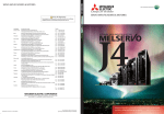
General-Purpose AC Servo
MR-J4 Servo amplifier
MR-J4-10_ to MR-J4-22K_
MR-J4W2-22B to MR-J4W2-1010B
MR-J4W3-222B and MR-J4W3-444B
WARNING
Instructions and Cautions for
Safe Use of AC Servos
It takes 15 minutes for capacitor discharging. Do not touch the unit and terminals immediately
after power off.
2.3.1 Peripheral device and power wiring
The followings are selected based on IEC/EN 61800-5-1, UL 508C, and CSA C22.2 No.14.
(1) Local wiring and crimping tool
Use only copper wires rated at 75 °C for wiring. The following table shows the wire sizes [AWG] and the crimp
terminal symbols rated at 75 °C.
Servo amplifier
J
MR-J4-10_/MR-J4-20_/MR-J4-40_/MR-J4-60_/MR-J4-70_/MR-J4-100_/
MR-J4-200_
MR-J4-350_
MR-J4-500_ (Note 1)
MR-J4-700_ (Note 1)
MR-J4-11K_ (Note 1)
MR-J4-15K_ (Note 1)
MR-J4-22K_ (Note 1)
MR-J4W_-_B
Note
Country/Region
Sales office
Tel/Fax
USA
Mitsubishi Electric Automation Inc.
500 Corporate Woods Parkway, Vernon Hills, IL 60061, USA
Tel :+1-847-478-2100
Fax :+1-847-478-0327
Mitsubishi Electric Europe B.V. German Branch
Gothaer Strasse 8, D-40880 Ratingen, Germany
Tel :+49-2102-486-0
Fax :+49-2102-486-1120
Mitsubishi Electric Europe B.V. Italian Branch
Viale Colleoni 7
1-20041 Agrate Brianza (Milano), Italy
Tel :+39-39-60531
Fax :+39-39-6053312
Germany
Italy
China
Mitsubishi Electric Automation (China) Ltd.
4F Zhi Fu Plazz, No. 80 Xin Chang Road
Shanghai 200003, China
Tel :+86-21-6120-0808
Fax :+86-21-6121-2444
Taiwan
Setsuyo Enterprise Co., Ltd.
6F, No.105 Wu-Kung 3rd Rd, Wu-Ku Hsiang, Taipei Hsine, Taiwan
Tel :+886-2-2299-2499
Fax :+886-2-2299-2509
Korea
Mitsubishi Electric Automation Korea Co., Ltd.
3F, 1480-6, Gayang-dong, Gangseo-gu, Seoul
157-200, Korea
Tel :+82-2-3660-9552
Fax :+82-2-3664-8372
Singapore
Mitsubishi Electric Asia Pte, Ltd.
307 Alexandra Road #05-01/02,
Mitsubishi Electric Building Singapore 159943
Tel :+65-6470-2460
Fax :+65-6476-7439
Copyright©2012 Mitsubishi Electric Corporation All Right Reserved.
Contents of the package
Unpack the product and check the rating plate to see if the servo motor is as you ordered.
Contents
Quantity
1
1
Servo amplifier
MELSERVO-J4 Series Instructions and Cautions for Safe Use of AC Servos (This guide)
Rating plate
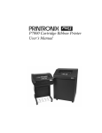
The following shows an example of rating plate for explanation of each item.
MODEL MR-J4-10B
AC SERVO
SER. S21001001
POWER : 100W
INPUT : 3AC/AC200-240V 0.9A/1.5A 50/60Hz
OUTPUT: 3PH170V 0-360Hz 1.1A
STD.: IEC/EN61800-5-1 MAN.: IB(NA)0300175
Max. Surrounding Air Temp.: 55°C
IP20
TOKYO 100-8310, JAPAN
MADE IN JAPAN
Serial number
Model
Capacity
Applicable power supply
Rated output current
Standard, Manual number
Ambient temperature
IP rating
KC certification number, The year and month of manufacture
Country of origin
Model
The following describes what each block of a model name
indicates. Not all combinations of the symbols are available.
Warning plate
Series
Number of axes
Number
Symbol of axes
1
W2
2
W3
3
Rated output
Symbol Rated output [kW]
10
0.1
20
0.2
40
0.4
60
0.6
70
0.75
100
1
200
2
350
3.5
500
5
700
7
11K
11
15K
15
22K
22
Software special specification
Blank, Sn, or Un
(n = 00 to 999)
Hardware special specification
Blank or 2 to 5 digit alphanumeric
(RJ, ED, PX, RU, RZ, etc.)
Corresponding
Symbol
Corresponding
A
General-purpose interface
B
SSCNET III/H
Symbol
22
44
77
1010
222
444
P+/C
14
14
14
14
12
10: a
8: b
6: d
4: f
1/0: h
14 (Note 4)
14: c
14
14: c
12: a
12: e
10: e
10: i
14
Rated output [kW]
A-axis B-axis C-axis
0.2
0.2
0.4
0.4
0.75
0.75
1
1
0.2
0.2
0.2
0.4
0.4
0.4
1.About the manuals
1.1 MELSERVO MR-J4 relevant manuals
This installation guide explains how to mount MR-J4 servo amplifiers. You can also check it with our website for free.
http://www.mitsubishielectric.com/fa/
If you have any questions about the operation or programming of the equipment described in this guide, contact your
local sales office.
In addition, when you mount a protective device, specific technical skills which are not detailed in the guide will be
required.
1.2 Purpose of this guide
This installation guide explains the safe operation of MR-J4 servo amplifiers for engineers of machinery manufacturers
and machine operators. This installation guide does not explain how to operate machines in which safe servo system is,
or will be integrated. For detailed information of the products, refer to each servo amplifier instruction manual.
1.3 Terms related to safety
1.3.1 IEC 61800-5-2 Stop function
STO function (Refer to IEC 61800-5-2:2007 4.2.2.2 STO.) The MR-J4 servo amplifiers have the STO function. The STO
function shuts down energy to servo motors, thus removing torque. This function electronically cuts off power supply in
the servo amplifier.
2. About safety
This chapter explains safety of users and machine operators. Please read the chapter carefully before mounting the
equipment. In this installation guide, the specific warnings and cautions levels are classified as follows.
WARNING
Indicates that incorrect handling may cause hazardous conditions, resulting in death or severe injury.
CAUTION
Indicates that incorrect handling may cause hazardous conditions, resulting in medium or slight injury to
personnel or may cause physical damage.
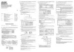
Installation direction and clearances
The devices must be installed in the
specified direction. Not doing so may
cause a malfunction.
Mount the servo amplifier on a cabinet
which meets IP54 in the correct vertical
direction to maintain pollution degree 2.
Note the followings for supplied
regenerative resistors of 11 kW to 22
servo amplifiers because they do
CAUTION kW
not have protect covers.
Touching the resistor will cause a
burn because the surface of the parts
is a resistive element and very high
temperature.
Even if the power turned off, touching
the resistor will cause an electric
shock because the capacitor of the
servo amplifier is charged for a while.
Symbol
a
b (Note 1)
c
d
e
f
g
h
i
j
Note
Crimp terminal (Note 2)
FVD5.5-4
8-4NS
FVD2-4
FVD14-6
FVD5.5-6
FVD22-6
FVD38-6
R60-8
FVD5.5-8
CB70-S8
DH-123
DH-124
TD-125
DH-113
DH-114
TD-113
TD-226
TD-213
10mm or
more
(Note 2)
Servo amplifier
10mm or
more
IP rating
Bottom
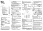
Note
(3-phase
230 V AC)
MC
MCCB
or fuse
L1 L2L3
L11
L21
1. For 11 kW to 22 kW servo amplifiers, the clearance
between the bottom and ground will be 120 mm or more.
2. For MR-J4-500_, the clearance on the left side will be 25
mm or more.
JST
(1-phase
230 V AC)
MCCB
or fuse
MC
L1 L2 L3
L11
L21
Power
(Note)
supply
MCCB
(3-phase
or fuse
400 V AC)
Transformer
(star-connected)
Cabinet side
Machine side
Servo motor
PE
U/V/W/PE
NF50-SVFU-10A (50 A frame 10 A)
15 A
30 A
40 A
60 A
80 A
125 A
150 A
300 A
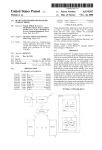
(3) Power supply
This servo amplifier can be supplied from star-connected supply with grounded neutral point of overvoltage
category III set forth in IEC/EN 60664-1. However, when you use the neutral point for single phase supply, a
reinforced insulating transformer is required in the power input section. For the interface power supply, use an
external 24 V DC power supply with reinforced insulation on I/O terminals.
(4) Grounding
To prevent an electric shock, always connect the protective earth (PE)
) of the servo amplifier to the protective earth (PE) of
terminal (marked
the cabinet. Do not connect two grounding cables to the same protective
PE
PE
terminals
terminals
earth (PE) terminal. Always connect cables to the terminals one-to-one.
If using a leakage circuit breaker, always ground the protective earth (PE) terminal of the servo amplifier to prevent
an electric shock. Only an RCD (earth-leakage current breaker) of type B can be used for the power supply side of
the product.
2.3.2 EU compliance
The MR-J4 servo amplifiers are designed to comply with the following directions to meet requirements for mounting,
using, and periodic technical inspections: Machinery directive (2006/42/EC), EMC directive (2004/108/EC), and Lowvoltage directive (2006/95/EC).
(1) EMC requirement
MR-J4 servo amplifiers comply with category C3 in accordance with EN 61800-3. As for I/O wires (max. length 10
m. However, 3 m for STO cable for CN8.) and encoder cables (max. length 50 m), connect them to a shielded
grounding. Use a EMC filter and surge protector on the primary side. The following shows recommended products.
EMC filter: Soshin Electric HF3000A-UN series
Surge protector: Okaya Electric Industries RSPD-250-U4 series
- MR-J4 Series are not intended to be used on a low-voltage public network which supplies domestic premises;
- radio frequency interference is expected if used on such a network.
The installer shall provide a guide for Installation and use, including recommended mitigation devices.
(2) For Declaration of Conformity (DoC)
Hereby, MITSUBISHI ELECTRIC EUROPE B.V., declares that the servo amplifiers are in compliance with the
necessary requirements and standards (2006/42/EC, 2004/108/EC and 2006/95/EC). For the copy of Declaration
of Conformity, contact your local sales office.
2.3.3 USA/Canada compliance
This servo amplifier is designed in compliance with UL 508C and CSA C22.2 No.14.
(1) Installation
The minimum cabinet size is 150% of each MR-J4 servo amplifier's volume. Also, design the cabinet so that the
ambient temperature in the cabinet is 55 °C or less. The servo amplifier must be installed in the metal cabinet. For
environment, the units should be used in open type (UL 50) and overvoltage category III or lower. The servo
amplifier needs to be installed at or below of pollution degree 2. For connection, use copper wires.
(2) Short-circuit current rating (SCCR)
Suitable For Use On A Circuit Capable Of Delivering Not More Than 100 kA rms Symmetrical Amperes, 500 Volts
Maximum.
(3) Overload protection characteristics
The MR-J4 servo amplifiers have solid-state servo motor overload protection. (It is set on the basis (full load
current) of 120% rated current of the servo amplifier.)
(4) Over-temperature protection for motor
Motor Over temperature sensing is not provided by the drive.
(5) Capacitor discharge
It takes 15 minutes for capacitor discharging. Do not touch the unit and terminals immediately after power off.
(6) Branch circuit protection
For installation in United States, branch circuit protection must be provided, in accordance with the National
Electrical Code and any applicable local codes.
For installation in Canada, branch circuit protection must be provided, in accordance with the Canada Electrical
Code and any applicable provincial codes.
2.3.4 South Korea compliance
This product complies with the Radio Wave Law (KC mark). However, some applications are being processed. For the
situation of compliance, contact your local sales office. Please note the following to use the product.
이 기기는 업무용 (A급) 전자파적합기기로서 판 매자 또는 사용자는 이 점을 주의하시기 바라며,가정외의
지역에서 사용하는 것을 목적으 로 합니다.
(The product is for business use (Class A) and meets the electromagnetic compatibility requirements. The seller and the
user must note the above point, and use the product in a place except for home. In addition, use an EMC filter, surge
protector, ferrite core, and line noise filter on the primary side for inputs. Use a ferrite core and line noise filter for
outputs. Use a distance greater than 30 m between the product and third party sensitive radio communications for an
MR-J4-22K_.)
2.4 General cautions for safety protection and protective measures
Observe the following items to ensure proper use of the MELSERVO MR-J4 servo amplifiers.
(1) For safety components and installing systems, only qualified personnel and professional engineers should
perform.
(2) When mounting, installing, and using the MELSERVO MR-J4 servo amplifier, always observe standards and
directives applicable in the country.
(3) The item about noises of the test notices in the manuals should be observed.
2.5 Residual risk
(1) Be sure that all safety related switches, relays, sensors, etc., meet the required safety standards.
(2) Perform all risk assessments and safety level certification to the machine or the system as a whole.
(3) If the upper and lower power module in the servo amplifier are shorted and damaged simultaneously, the servo
motor may make a half revolution at a maximum.
(4) Only qualified personnel are authorized to install, start-up, repair or service the machines in which these
components are installed. Only trained engineers should install and operate the equipment. (ISO 13849-1 Table
F.1 No.5)
(5) Separate the wiring for safety function from other signal wirings. (ISO 13849-1 Table F.1 No.1)
(6) Protect the cables with appropriate ways (routing them in a cabinet, using a cable guard, etc.).
(7) Keep the required clearance/creepage distance depending on voltage you use.
2.6 Disposal
Disposal of unusable or irreparable devices should always occur in accordance with the applicable country-specific
waste disposal regulations. (Example: European Waste 16 02 14)
Note. In regular transport packaging
8.Technical data
MR-J4-10_/MR-J4-20_/MR-J4-40_/MR-J4-60_/
MR-J4-100_/MR-J4-200_/MR-J4-350_/
Item
MR-J4-70_/MR-J4W2-22B/MR-J4W2-44B/
MR-J4-500_/MR-J4-700_/MR-J4W2-1010B/
MR-J4-11K_/MR-J4-15K_/MR-J4-22K_
MR-J4W2-77B/MR-J4W3-222B/MR-J4W3-444B
Main circuit (line voltage) 3-phase or 1-phase 200 V AC to 240 V AC, 50 Hz /60 Hz
3-phase 200 V AC to 240 V AC, 50 Hz/60 Hz
Power Control circuit (line voltage)
1-phase 200 V AC to 240 V AC, 50/60 Hz
supply
24 V DC, (required current capacity: MR-J4-_A, 500 mA; MR-J4-_B, 300 mA; MR-J4W2-_B, 350 mA; MRInterface (SELV)
J4W3-_B, 450 mA)
Control method
Sine-wave PWM control, current control method
Safety function (STO)
EN ISO 13849-1 category 3 PL d, EN 61508 SIL 2, EN 62061 SIL CL 2, and EN 61800-5-2 SIL 2
IEC/EN 61800-5-2
Mean time to dangerous failure
MTTFd ≥ 100 [years]
Effectiveness of fault monitoring of
DC = 90 [%]
a system or subsystem
Average probability of dangerous
PFH
= 1.68 × 10⁻¹⁰ [1/h]
failures per hour
Mission time
TM = 20 [years]
Response performance
8 ms or less (STO input off → energy shut off)
Pollution degree
2 (IEC/EN 60664-1)
Overvoltage category
III (IEC/EN 60664-1)
Protection class
I (IEC/EN 61800-5-1)
Short-circuit current rating (SCCR)
100 kA
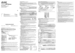
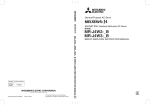
8.2 Servo amplifier dimensions
H
Front
Side
W
D
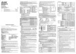
(4) 1-phase input for MR-J4 multi-axis servo amplifier
Servo
amplifier
Servo
motor
MCCB
MC
CNP1 CN2C
or fuse
(L1 L2 L3)
CNP2 CNP3C
L11
CN8
L21
Power
STO
(Note)
supply
CN1
MCCB
Controller
(3-phase
or
fuse
CN2A CN2B Encoder cable
400 V AC)
PE
Transformer
CNP3A CNP3B
(star-connected)
Cabinet side
Machine side
Servo motor
Servo motor
(1-phase
230 V AC)
(3-phase
230 V AC)
Servo
amplifier
MCCB
or fuse
MC
Servo
motor
CNP1 CN2C
(L1 L2 L3)
CNP2 CNP3C
L11
CN8
L21
Power
STO
(Note)
supply
CN1
MCCB
Controller
(3-phase
or fuse
CN2A CN2B Encoder cable
400 V AC)
PE
Transformer
CNP3A CNP3B
(star-connected)
Cabinet side
Machine side
Servo motor
Servo motor
a1
c
Servo amplifier
d1
e
c
a
d
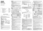
5. Signals
5.1 Signal
The following shows MR-J4-10B signals as a typical
example. For other servo amplifiers, refer to each servo
amplifier instruction manual.
CN3
STO I/O signal
connector
CN8
1
2
LG
2
1
DI1
4
STO1
3
STOCOM
MO1
6
TOFB1
5
STO2
LA
8
TOFCOM
7
TOFB2
LZ
4
3
DOCOM
6
5
DICOM
7
8
LB
9
10
INP
DICOM
DI2
14
MO2
16
LAR
18
LZR
20
Device
STO1
STO2
LG
13
Forced stop 2
Common terminal for input signals
STO1/STO2
STO1 state input
STO2 state input
Connector
CN3
Pin No.
20
3
CN8
4
5
Output device
MBR
15
Symbol
ALM
TOFCOM
17
LBR
TOFB1
TOFB2
Device
Connector
Common terminal for monitor output
signal in STO state
CN8
Monitor output signal in STO1 state
Monitor output signal in STO2 state
Symbol
DICOM
DOCOM
SD
Device
Digital I/F power supply input
Digital I/F common
Shield
19
Pin No.
8
6
7
Power supply
DI3
EM2
Connector
Pin No.
5, 10
3
Plate
CN3
6. Maintenance and service
WARNING
To avoid an electric shock, only qualified personnel should attempt inspections. For repair and
parts replacement, contact your local sales office.
CAUTION
Do not perform insulation resistance test on the servo amplifier. Otherwise, it may cause a
malfunction.
Do not disassemble and/or repair the equipment on customer side.
Servo amplifier
L1
L2
L3
Tightening torque [N•m]
N- P3 P4 P+ C D L11 L21 U
Smoothing capacitor
Relay
Cooling fan
(Note 1) MR-J4 1axis servo amplifier
Rotary servo motor
Direct drive motor
Battery
backup time
Rotary servo motor
(Note 2) MR-J4
multi-axis servo
amplifier
Direct drive motor
(Note 3) Battery life
Note
V
W PE
0.8
0.8
1.2
1.2
1.2
1.2
3.0
6.0
1.2
1. The data-holding time by the battery using MR-BAT6V1SET. Replace the batteries within three years since the operation start whether the
power supply of the servo amplifier is on/off. If the battery is used out of specification, [AL. 25 Absolute position erased] may occur. For
other batteries, refer to each servo amplifier instruction manual.
2. The data-holding time by the battery using five MR-BAT6V1s. Replace the batteries within three years since the operation start whether the
power supply of the servo amplifier is on/off. If the battery is used out of specification, [AL. 25 Absolute position erased] may occur. For
other batteries, refer to each servo amplifier instruction manual.
3. Quality of the batteries degrades by the storage condition. The battery life is 5 years from the production date regardless of the connection
status.
4. The characteristic of smoothing capacitor is deteriorated due to ripple currents, etc. The life of the capacitor greatly depends on ambient
temperature and operating conditions. The capacitor will reach the end of its life in 10 years of continuous operation in normal airconditioned environment (40 °C surrounding air temperature or less).
5. The power-on time ratio 25% is equivalent to 8 hours power on for a weekday and off for a weekend.
CAUTION
Transport the products correctly according to their mass.
Stacking in excess of the limited number of product packages is not allowed.
a1
6
12
45
6
6
12
12
6
6
6
Variable dimensions [mm]
b
c
d
156 ± 0.5
6
156 ± 0.5
6
42 ± 0.3
156 ± 0.5
6
78 ± 0.3
235 ± 0.5
7.5
93 ± 0.3
285 ± 0.5
7.5
160 ± 0.5
380 ± 0.5
10
196 ± 0.5
376 ± 0.5
12
236 ± 0.5
156 ± 0.5
6
156 ± 0.5
6
73 ± 0.3
156 ± 0.5
6
73 ± 0.3
d1
93 ± 0.3
160 ± 0.5
196 ± 0.5
236 ± 0.5
Screw size
e
M5
M5
M5
M5
M5
M5
M10
M5
M5
M5
MR-J4 installation checklist for manufacturer/installer
The following items must be satisfied by the initial test operation at least. The manufacturer/installer must be
responsible for checking the standards in the items.
Maintain and keep this checklist with related documents of machines to use this for periodic inspection.
1. Is it based on directive/standard applied to the machine?
Yes [ ], No [ ]
2. Is directive/standard contained in Declaration of Conformity (DoC)?
Yes [ ], No [ ]
3. Does the protection instrument conform to the category required?
Yes [ ], No [ ]
4. Are electric shock protective measures (protection class) effective?
Yes [ ], No [ ]
5. Is the STO function checked (test of all the shut-off wiring)?
Yes [ ], No [ ]
Checking the items will not be instead of the first test operation or periodic inspection by professional engineers.
[Warranty]
1. Warranty period and coverage
We will repair any failure or defect hereinafter referred to as "failure" in our FA equipment hereinafter referred to as the
"Product" arisen during warranty period at no charge due to causes for which we are responsible through the distributor from
which you purchased the Product or our service provider. However, we will charge the actual cost of dispatching our engineer
for an on-site repair work on request by customer in Japan or overseas countries. We are not responsible for any on-site
readjustment and/or trial run that may be required after a defective unit are repaired or replaced.
(1) You are requested to conduct an initial failure diagnosis by yourself, as a general rule. It can also be carried out by us or our
service company upon your request and the actual cost will be charged. However, it will not be charged if we are responsible
for the cause of the failure.
(2) This limited warranty applies only when the condition, method, environment, etc. of use are in compliance with the terms and
conditions and instructions that are set forth in the instruction manual and user manual for the Product and the caution label
affixed to the Product.
(3) Even during the term of warranty, the repair cost will be charged on you in the following cases.
(i)
Life guideline
(Note 4) 10 years
Number of power-on, forced stop and controller forced stop times: 100 000 times
Number of on and off for STO: 1,000,000 times
10,000 hours to 30,000 hours (2 years to 3 years)
Approximately 20,000 hours (equipment power supply: off, ambient temperature: 20 °C)
Approximately 29,000 hours (power-on time ratio: 25%, ambient temperature: 20 °C)
(Note 5)
Approximately 5,000 hours (equipment power supply: off, ambient temperature: 20 °C)
Approximately 15,000 hours (power-on time ratio: 25%, ambient temperature: 20 °C)
(Note 5)
Approximately 40,000 hours/2 axes, 30,000 hours/3 axes, or 10,000 hours/8 axes
(equipment power supply: off, ambient temperature: 20 °C)
Approximately 55,000 hours/2 axes, 38,000 hours/3 axes, or 15,000 hours/8 axes
(power-on time ratio: 25%, ambient temperature: 20 °C) (Note 5)
Approximately 10,000 hours/2 axes, 7,000 hours/3 axes, or 5,000 hours/4 axes
(equipment power supply: off, ambient temperature: 20 °C)
Approximately 15,000 hours/2 axes, 13,000 hours/3 axes, or 10,000 hours/4 axes
(power-on time ratio: 25%, ambient temperature: 20 °C) (Note 5)
5 years from date of manufacture
7. Transportation and storage
a
6
12
6
6
6
12
12
6
6
6
[Limitations]
(2) Servo motor bearings, brake section, etc. for unusual noise.
(3) Check the cables and the like for scratches or cracks. Perform periodic inspection according to operating conditions.
(4) Check that the connectors are securely connected to the servo motor.
(5) Check that the wires are not coming out from the connector.
(6) Check for dust accumulation on the servo amplifier.
(7) Check for unusual noise generated from the servo amplifier.
(8) Check the servo motor shaft and coupling for connection.
6.2 Parts having service lives
Service lives of the following parts are listed below. However, the service lives vary depending on operation and
environment. If any fault is found in the parts, they must be replaced immediately regardless of their service lives. For
parts replacement, please contact your local sales office.
Part name
MR-J4-10_/MR-J4-20_/MR-J4-40_/MR-J4-60_
MR-J4-70_/MR-J4-100_
MR-J4-200_/MR-J4-350_
MR-J4-500_
MR-J4-700_
MR-J4-11K_/MR-J4-15K_
MR-J4-22K_
MR-J4W2-22B/MR-J4W2-44B
MR-J4W2-77B/MR-J4W2-1010B
MR-J4W3-222B/MR-J4W3-444B
The term of warranty for Product is twelve (12) months after your purchase or delivery of the Product to a place designated by
you or eighteen (18) months from the date of manufacture whichever comes first ("Warranty Period"). Warranty period for
repaired Product cannot exceed beyond the original warranty period before any repair work.
1.2
1.2
1.2
3.0
6.0
0.8
1.0
1.4
2.1
2.3
4.0
6.2
13.4
18.2
1.4
2.3
2.3
[Term]
6.1 Inspection items
It is recommended that the following points periodically be checked.
(1) Check for loose terminal block screws. Retighten any loose screws.
MR-J4-10_/MR-J4-20_/MR-J4-40_/
MR-J4-60_/MR-J4-70_/MR-J4-100_/MR-J4-200_/MR-J4-350_
MR-J4-500_
MR-J4-700_
MR-J4-11K_/MR-J4-15K_
MR-J4-22K_
MR-J4W_-_B
Mass [kg]
9.Check list for user documentation
Input device
Symbol
EM2
STOCOM
11
12
5.2 I/O device
MR-J4-10_/MR-J4-20_
MR-J4-40_/MR-J4-60_
MR-J4-70_/MR-J4-100_
MR-J4-200_
MR-J4-350_
MR-J4-500_
MR-J4-700_
MR-J4-11K_/MR-J4-15K_
MR-J4-22K_
MR-J4W2-22B/MR-J4W2-44B
MR-J4W2-77B/MR-J4W2-1010B
MR-J4W3-222B/MR-J4W3-444B
8.3 Mounting hole
b
Note. When the wire sizes of L1 and L11 are the same, MCCB or fuse is not required.
The control circuit connectors described by rectangles are safely separated from the main circuits described by circles.
The connected motors will be limited as follows.
(1) HG/HF/HC/HA series servo motors (Mfg.: Mitsubishi Electric)
(2) Using a servo motor complied with IEC60034-1 and Mitsubishi Electric encoder (OBA, OSA)
Variable dimension table [mm]
W
H
D
40
168
135
40
168
170
60
168
185
90
168
195
90
168
195
105
250
200
172
300
200
220
400
260
260
400
260
60
168
195
85
168
195
85
168
195
Servo amplifier
Cabinet side
Machine side
Servo motor
Encoder
(2) Selection example of MCCB and fuse
When a servo amplifier is protected by T class fuses or circuit breaker having an interrupting rating not less than
300 A effective value and 240 V maximum, use T class fuses or molded-case circuit breaker (UL489 Listed
MCCB) as the following table. The T class fuses and molded-case circuit breakers in the table are selected
examples based on rated I/O of the servo amplifiers. When you select a smaller capacity servo motor to connect it
to the servo amplifier, you can also use smaller capacity T class fuses or molded-case circuit breaker than ones in
the table. For selecting ones other than Class T fuses and molded-case circuit breakers below, refer to each servo
amplifier instruction manual.
Servo amplifier
P+
C
D
NCN8
STO
CN1
Controller
CN2 Encoder cable
Encoder
(3) 3-phase input for MR-J4 multi-axis servo amplifier
Operation, storage
Transportation
Altitude
Environment
0 to 55 Class 3K3 (IEC/EN 60721-3-3)
-20 to 65 Class 2K4 (IEC/EN 60721-3-2)
-20 to 65 Class 1K4 (IEC/EN 60721-3-1)
5 %RH to 90 %RH
10 Hz to 57 Hz with constant deviation of 0.075 mm
57 Hz to 150 Hz with constant acceleration of 9.8 m/s2 (1 g) to IEC/EN 61800-5-1 (Test Fc
of IEC 60068-2-6)
5.9 m/s2 (0.6 g)
Class 2M3 (IEC/EN 60721-3-2)
Class 1M2 (IEC/EN 60721-3-2)
2
Except terminal block IP20 (IEC/EN 60529) and fan finger guard
Open type (UL 50)
Max. 1000 m above sea level
Max. 10000 m above sea level
8.1 MR-J4 servo amplifier
Servo amplifier
P+
C
D
NCN8
STO
CN1
Controller
CN2 Encoder cable
PE
U/V/W/PE
Operation
Transportation (Note)
Storage
Pollution degree
40mm or
more
(Note 1)
The following shows representative configuration examples to conform to the IEC/EN/UL/CSA standards.
(1) 3-phase input for MR-J4 1-axis servo amplifier
(2) 1-phase input for MR-J4 1-axis servo amplifier
Power
(Note)
supply
MCCB
(3-phase
or fuse
400 V AC)
Transformer
(star-connected)
Fuse (300 V)
10 A
Test values
Vibration load
The installation complies with IEC/EN 60204-1. The voltage supply to machines must be 20 ms
of immunity to instantaneous power failures as specified in IEC/EN 60204-1.
Connecting a servo motor for different axis to U, V, W, or CN2_ of the servo amplifier may cause
a malfunction.
4: f
2: g
2/0: j
14
Molded-case circuit breaker (240 V AC)
NF50-SVFU-5A (50 A frame 5 A)
Item
Operation
[°C]
Transportation (Note)
[°C]
Storage (Note)
[°C]
Ambient humidity Operation, transportation, storage
Ambient
temperature
80 mm or longer
for wiring
CAUTION
8: b
1. Coat the crimping part with an insulation tube.
2. Some crimp terminals may not be mounted depending on the size. Make sure to use the recommended ones or equivalent ones.
NF50-SVFU-15A (50 A frame 15 A)
NF50-SVFU-20A (50 A frame 20 A)
NF50-SVFU-30A (50 A frame 30 A)
NF50-SVFU-40A (50 A frame 40 A)
NF100-CVFU-60A (100 A frame 60 A)
NF100-CVFU-80A (100 A frame 80 A)
NF225-CWU-125A (225 A frame 125 A)
40mm or
more
Do not hold the front cover to transport the servo amplifier. Otherwise, it may drop.
Install the servo amplifier and servo motor in a load-bearing place in accordance with the
Instruction Manual.
Do not get on or put heavy load on the equipment.
For detailed information on the option battery’s transportation and handing refer to the instruction
manual.
When you keep or use it, please fulfill the following environment.
Cabinet
Turn off the molded-case circuit breaker (MCCB) to avoid electrical shocks or damages to the
product before starting the installation or wiring.
Manufacturer
DH-112
Top
WARNING
Dice
DH-122
Cabinet
4. Electrical Installation and configuration diagram
Table: Recommended crimp terminals
Servo amplifier-side crimp terminals
Applicable tool
Body
Head
YNT-1210S
YHT-8S
YNT-1614
YF-1
YNE-38
YNT-1210S
YF-1
YNE-38
YF-1
YNE-38
YF-1
YET-60-1
YNT-1210S
YF-1
YET-150-1
CAUTION
3. Mounting/dismounting
12
Note. For 1-phase 200 V AC power input
This guide uses recycled paper.
Specifications are subject to change without notice.
Printed in Japan
L11/L21
U/V/W/
(Note 3)
1. To connect these models to a terminal block, be sure to use the screws that come with the terminal block.
2. Alphabets in the table indicate crimping tools. Refer to the following table for the crimp terminals and crimping tools.
3. Select wire sizes depending on the rated output of the servo motors. The values in the table are sizes based on rated output of the servo
amplifiers.
4. Use the crimp terminal c for the PE terminal of the servo amplifier.
Servo amplifier
MR-J4-10_/MR-J4-20_/MR-J4-40_/MR-J4-60_/MR-J4-70_/MR-J4W2-22B
MR-J4-60_ (Note)/MR-J4-70_ (Note)/MR-J4-100_/MR-J4W2-22B (Note)/
MR-J4W2-44B/MR-J4W2-77B/MR-J4W3-222B/MR-J4W3-444B
MR-J4-200_/MR-J4W2-44B (Note)/MR-J4W2-1010B
MR-J4-350_/MR-J4W2-77B (Note)/MR-J4W3-444B (Note)
MR-J4-500_
MR-J4-700_
MR-J4-11K_
MR-J4-15K_
MR-J4-22K_
HEAD OFFICE: TOKYO BLDG MARUNOUCHI TOKYO 100-8310
IB(NA)0300175-J(1309)MEE
Wire [AWG] (Note 2)
L1/L2/L3
2.7 Lithium battery transportation
To transport lithium batteries, take actions to comply with the instructions and regulations such as the United Nations
(UN), the International Civil Aviation Organization (ICAO), and the International Maritime Organization (IMO).
The battery options (MR-BAT6V1SET and MR-BAT6V1) are assembled batteries from two batteries (lithium metal
battery CR17335A) which are not subject to the dangerous goods (Class 9) of the UN Recommendations.
Servo amplifier
2.1 Professional engineer
Only professional engineers should mount MR-J4 servo amplifiers.
Here, professional engineers should meet the all conditions below.
(1) Persons who took a proper engineering training or qualified persons who are engaged in electrical equipment
Please note if you can take a proper engineering training at your local Mitsubishi Electric office. Contact your local
sales office for schedules and locations.
(2) Persons who can access to operating manuals for the protective devices (e.g. light curtain) connected to the safety
control system. A person who have read and familiarized himself/herself with the manuals.
2.2 Applications of the devices
MR-J4 servo amplifiers comply with the following safety standards.
ISO/EN ISO 13849-1 Category 3 PL d, IEC/EN 62061 SIL CL 2, IEC/EN 61800-5-2 SIL 2 (STO), IEC/EN 61800-5-1,
IEC/EN 61800-3, IEC/EN 60204-1
In addition, MR-J4 servo amplifiers can be used with the MR-J3-D05 safety logic unit or safety PLCs.
2.3 Correct use
Always use the MR-J4 servo amplifiers within specifications (voltage, temperature, etc. Refer to each instruction manual
for details.). Mitsubishi Electric Co. accepts no claims for liability if the equipment is used in any other way or if
modifications are made to the device, even in the context of mounting and installation.
a failure caused by your improper storing or handling, carelessness or negligence, etc., and a failure caused by your hardware or software
problem
(ii) a failure caused by any alteration, etc. to the Product made on your side without our approval
(iii) a failure which may be regarded as avoidable, if your equipment in which the Product is incorporated is equipped with a safety device
required by applicable laws and has any function or structure considered to be indispensable according to a common sense in the industry
(iv) a failure which may be regarded as avoidable if consumable parts designated in the instruction manual, etc. are duly maintained and
replaced
(v) any replacement of consumable parts (battery, fan, smoothing capacitor, etc.)
(vi) a failure caused by external factors such as inevitable accidents, including without limitation fire and abnormal fluctuation of voltage, and
acts of God, including without limitation earthquake, lightning and natural disasters
(vii) a failure generated by an unforeseeable cause with a scientific technology that was not available at the time of the shipment of the Product
from our company
(viii) any other failures which we are not responsible for or which you acknowledge we are not responsible for
2. Term of warranty after the stop of production
(1) We may accept the repair at charge for another seven (7) years after the production of the product is discontinued. The
announcement of the stop of production for each model can be seen in our Sales and Service, etc.
(2) Please note that the Product (including its spare parts) cannot be ordered after its stop of production.
3. Service in overseas countries
Our regional FA Center in overseas countries will accept the repair work of the Product. However, the terms and conditions of
the repair work may differ depending on each FA Center. Please ask your local FA center for details.
4. Exclusion of responsibility for compensation against loss of opportunity, secondary loss, etc.
Whether under or after the term of warranty, we assume no responsibility for any damages arisen from causes for which we are
not responsible, any losses of opportunity and/or profit incurred by you due to a failure of the Product, any damages, secondary
damages or compensation for accidents arisen under a specific circumstance that are foreseen or unforeseen by our company,
any damages to products other than the Product, and also compensation for any replacement work, readjustment, start-up test
run of local machines and the Product and any other operations conducted by you.
5. Change of Product specifications
Specifications listed in our catalogs, manuals or technical documents may be changed without notice.
6. Application and use of the Product
(1) For the use of our General-Purpose AC Servo, its applications should be those that may not result in a serious damage even if
any failure or malfunction occurs in General-Purpose AC Servo, and a backup or fail-safe function should operate on an
external system to General-Purpose AC Servo when any failure or malfunction occurs.
(2) Our General-Purpose AC Servo is designed and manufactured as a general purpose product for use at general industries.
Therefore, applications substantially influential on the public interest for such as atomic power plants and other
power plants of electric power companies, and also which require a special quality assurance system, including
applications for railway companies and government or public offices are not recommended, and we assume no
responsibility for any failure caused by these applications when used.
In addition, applications which may be substantially influential to human lives or properties for such as airlines,
medical treatments, railway service, incineration and fuel systems, man-operated material handling equipment,
entertainment machines, safety machines, etc. are not recommended, and we assume no responsibility for any
failure caused by these applications when used.
We will review the acceptability of the abovementioned applications, if you agree not to require a specific quality
for a specific application. Please contact us for consultation.