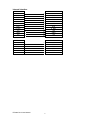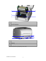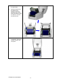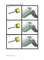
1
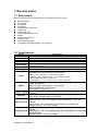
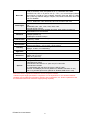
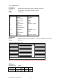
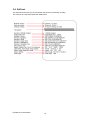
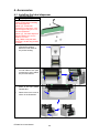
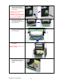
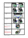
User Manual EZ1000 Plus P/N. 920-012411-04 Rev. B, 05.2010 FCC COMPLIANCE STATEMENT FOR AMERICAN USERS This equipment has been tested and found to comply with the limits for a CLASS A digital device, pursuant to Part 15 of the FCC Rules. These limits are designed to provide reasonable protection against harmful interference when the equipment is operated in a commercial environment. This equipment generates, uses, and can radiate radio frequency energy and, if not installed and used in accordance with the instructions, may cause harmful interference to radio communications. Operation of this equipment in a residential area is likely to cause harmful interference in which case the user will be required to correct the interference at own expense. EMS AND EMI COMPLIANCE STATEMENT FOR EUROPEAN USERS This equipment has been tested and passed with the requirements relating to electromagnetic compatibility based on the standards EN 55022:1998+A1:2000+A2:2003, CISPR 22 , Class A EN 55024:1998+A1:2001+A2:2003, IEC 61000- 4 Series EN 61000-3-2 / 2000 & EN 61000-3-3 / 1995. The equipment has also been tested and passed in accordance with the European Standard EN55022 for both radiated and conducted emissions limits. EZ PLUS SERIES TO WHICH THIS DECLARATION RELATES IS IN CONFORMITY WITH THE FOLLOWING STANDARDS EN55022 : 1998,CLSPR 22, Class A / EN55024 : 1998IEC 61000-4 Serial / EN61000-3-2 : 2000 / EN 6100-3-3 : 1995 / CFR 47, Part 15/CISPR 22 3rd Edition : 1997, Class A / ANSI C63.4 : 2001 / CNS 13438 / IEC60950-1 : 2001 / GB4943 : 2001 / GB9254 : 1998 / GB17625.1 : 2003 /EN60950-1 : 2001 CAUTION Danger of explosion if battery is incorrectly replaced. Replace only with the equivalent type recommended by the manufacturer. Dispose of used batteries according to the manufacturer’s instructions. Specifications are subject to change without notice. EZ1000 Plus User Manual 1 Safety instructions Please read the following instructions carefully. 1. Keep the equipment away from humidity. 2. Before you connect the equipment to the power outlet, please check the voltage of the power source. 3. Make sure the printer is off before plugging the power connector into the power jack. 4. It is recommended that you connect the printer to a surge protector to prevent possible transient overvoltage damage. 5. Be careful not to get liquid on the equipment to avoid electrical shock. 6. For safety and warranty reasons, ONLY qualified service personnel should open the equipment. 7. Do not repair or adjust energized equipment under any circumstances. EZ1000 Plus User Manual 2 1. BARCODE PRINTER ................................................................... 4 1-1. Box content ..................................................................................................................... 4 1-2. Specifications .................................................................................................................. 4 1-3. Interfaces ........................................................................................................................ 6 1-4. Getting to know your printer ............................................................................................ 8 2. PRINTER SETUP ....................................................................... 10 2-1. Loading the ribbon ........................................................................................................ 10 2-2. Loading the label roll ..................................................................................................... 12 2-3. Installing the label supply hub ....................................................................................... 13 2-4. Preparing for tag printing .............................................................................................. 14 2-5. Connecting the printer to the host computer................................................................. 14 2-6. Installing the driver ........................................................................................................ 15 3. OPERATOR PANEL .................................................................. 17 3-1. FEED button ................................................................................................................. 17 3-2. LED indicators ............................................................................................................... 17 3-3. Label size calibration .................................................................................................... 17 3-4. Self test ......................................................................................................................... 18 3-5. Error alerts .................................................................................................................... 19 4. ACCESSORIES.......................................................................... 20 4-1. Installing the label dispenser ........................................................................................ 20 4-2. Installing the cutter ........................................................................................................ 23 4-3. Installing the Ethernet module ...................................................................................... 25 4-4. Installing the WLAN module ......................................................................................... 27 4-5. Installing the CF card adapter ....................................................................................... 31 4-6. Instructions for using the CF card ................................................................................. 32 5. MAINTENANCE AND ADJUSTMENT ....................................... 33 5-1. Cleaning the print head ................................................................................................. 33 5-2. Adjusting the print head pressure ................................................................................. 33 5-3. Adjusting the print line................................................................................................... 34 5-4. Adjusting the cutter ....................................................................................................... 34 5-5. Troubleshooting ............................................................................................................ 35 EZ1000 Plus User Manual 3 1. Barcode printer 1-1. Box content Please check that all of the following items are included with your printer: Barcode printer Power cord AC adapter USB cable Parallel cable (Centronics) Label stock Label supply hub Label guide plates (set of 2) Ribbon Ribbon hubs (set of 2) Cleaning card Quick reference guide CD (with QLabel label software / user manual) 1-2. Specifications Model Print Method Resolution Print Speed Print Width EZ1100 Plus Thermal Transfer / Direct Thermal 203 dpi (8 dot/mm) 4 IPS (102 mm/s) 4.25” (108 mm) Min. 0.16” (4 mm)** Print Length Max. 68” (1727 mm) 4MB Flash (2MB for user storage) ; 8MB SDRAM Memory Adjustable reflective sensor. Fixed transmissive sensor, central aligned Sensor Type Types: Continuous form, gap labels, black mark sensing, and punched hole; label length set by auto sensing or programming Width: 1” (25.4 mm) Min. - 4.64” (118 mm) Max. Media Thickness: 0.003” (0.06 mm) Min. - 0.01” (0.25 mm) Max. Label roll diameter: Max. 5” (127 mm) Core diameter: 1”, 1.5”, 3” (25.4 mm, 38.1 mm, 76.2 mm) Types: Wax, wax/resin, resin Length: 981’ (300 m) Width: 1.18” Min - 4.33” (30 mm - 110 mm) Max Ribbon Ribbon roll diameter.: 2.67“ (68 mm) Core diameter: 1” (25.4 mm) EZPL, GEPL (Godex Eltron® Printer Language), GZPL (Godex Zebra® Printer Printer Language Language) Label design software: QLabel-IV (for EZPL only) Software Driver & DLL: Windows 2000, XP and Vista Bitmap fonts: 6, 8, 10, 12, 14, 18, 24, 30, 16X26 and OCR A & B Bitmap fonts 90°, 180°, 270° rotatable, single characters 90°, 180°, 270° Resident Fonts rotatable Bitmap fonts 8 times expandable in horizontal and vertical directions Scalable fonts 90°, 180°, 270° rotatable Bitmap fonts 90°, 180°, 270° rotatable, single characters 90°, 180°, 270° rotatable Download Fonts Asian fonts 90°, 180°, 270° rotatable and 8 times expandable in horizontal and vertical directions Scalable fonts 90°, 180°, 270° rotatable EZ1000 Plus User Manual 4 Barcodes Code Pages Graphics Interfaces Control Panel Power Environment Humidity Agency Approvals 1-D Bar codes: Code 39, Code 93, Code 128 (subset A, B, C), UCC/EAN-128 K-Mart, UCC/EAN-128, UPC A / E (add on 2 & 5), I 2 of 5, I 2 of 5 with Shipping Bearer Bars, EAN 8 / 13 (add on 2 & 5), Codabar, Post NET, EAN 128, DUN 14, HIBC, MSI (1 Mod 10), Random Weight, Telepen, FIM, China Postal Code, RPS 128 and GS1 DataBar 2-D Bar codes: PDF417, Datamatrix code, MaxiCode, QR code and Micro QR code CODEPAGE 437, 850, 851, 852, 855, 857, 860, 861, 862, 863, 865, 866, 869, 737 WINDOWS 1250, 1251, 1252, 1253, 1254, 1255 Unicode (UTF8, UTF16) Resident graphic file types are BMP and PCX, other graphic formats are downloadable from the software Serial port: RS-232 (DB-9) USB port (default on) Parallel port: Centronics 36-pin Two bi-color status-LEDs: Ready, Status Control key: FEED Auto Switching 100-240VAC, 50-60Hz Operation temperature: 41°F to 104°F (5°C to 40°C) Storage temperature: -4°F to 122°F (-20°C to 50°C) Operation: 30-85%, non-condensing. Storage: 10-90%, non-condensing. CE(EMC), FCC Class A, CB, cUL, CCC Length: 11.2” (285 mm) Height: 6.8” (171 mm) Width: 8.9” (226 mm) 6 lbs (2.72Kg), excluding consumables Weight Rotary Cutter Label Dispenser (peel) External label roll holder for 10” (250 mm) O.D. label rolls External label rewinder Options CF card adapter with real time clock (max. 1GB CF card) Ethernet 10/100Mbps print server (default off; disables USB when in use) 802.11 b/g wireless print server (default off; disables USB when in use) *Specifications are subject to change without notice. All company and/or product names are trademarks and/or registered trademarks of their respective owners. ** Minimum print height specification compliance can be dependent on non-standard material variables such as label type, thickness, spacing, liner construction, etc. Godex is pleased to test non-standard materials for minimum height printing capability. Dimension EZ1000 Plus User Manual 5 1-3. Interfaces Parallel port Handshaking Interface cable Pinout Pin No. 1 2–9 10 11 12 13 14 15 16 17 18 19–30 31 32 33 34–35 36 : DSTB is sent to the printer, BUSY to the host computer : Parallel cable compatible with IBM computers : See below Function /Strobe Data 0-7 /Acknowledge Busy /Paper empty /Select /Auto-Linefeed N/C Signal Gnd Chassis Gnd +5V, max 500mA Signal Gnd /Initialize /Error Signal Ground N/C /Select-in Data source Computer / printer Computer Printer Printer Printer Printer Computer / printer Computer Computer / printer Printer Computer / printer Serial port Default settings : Baud rate 9600, no parity, 8 data bits, 1 stop bit, XON/XOFF protocol and RTS/CTS RS232 housing (9-pin to 9-pin) DB9 socket --1 RXD 2 TXD 3 DTR 4 GND 5 DSR 6 RTS 7 CTS 8 RI 9 Computer 1 2 3 4 5 6 7 8 9 DB9 plug +5V, max 500mA TXD RXD N/C GND RTS CTS RTS N/C Printer 【Note】 The total current to the parallel and serial ports may not exceed 500 mA. USB port Connector type : Type B Pin No. 1 2 3 4 Function VBUS D- D+ GND EZ1000 Plus User Manual 6 Internal interface UART1 wafer N.C TXD RXD CTS GND RTS E_MD RTS E_RST +5V GND +5V UART2 wafer +5V CTS TXD RTS RXD GND 1 2 3 4 5 6 7 8 9 10 11 12 1 2 3 4 5 6 EZ1000 Plus User Manual 1 2 3 4 5 6 7 8 9 10 11 12 Ethernet module N.C RXD TXD RTS GND CTS E_MD CTS E_RST +5V GND +5V 1 2 3 4 5 6 Add-on module +5V RTS RXD CTS TXD GND 7 1-4. Getting to know your printer 1 2 3 5 4 6 7 8 1. 2. 3. 4. 5. 6. 7. 8. Release buttons for opening the printer cover Printer cover Label supply hub Ribbon feed mechanism Print mechanism Ribbon rewind hub and empty ribbon core Release catches (left/right) Front cover 4 1 2 3 5 1. 2. 3. 4. 5. LED indicator (READY) LED indicator (STATUS) FEED button CF card slot cover Screws for adjusting the print head pressure (left/right) EZ1000 Plus User Manual 8 1 4 2 5 3 1. 2. 3. 4. 5. Ribbon supply hub Label guides Platen roller Print line adjustment Label sensor 3 4 5 6 7 1 2 1. Feed slot for continuous labels 2. On/off switch 3. Ethernet port (optional) 4. USB port 5. Parallel port 6. Serial port (RS-232) 7. Power jack * Ports and interfaces vary depending on the model. EZ1000 Plus User Manual 9 2. Printer setup This printer supports the following printing methods: Thermal transfer Requires a ribbon for transferring a printed image to a medium. printing (TTP) Direct thermal Does not require a ribbon, only thermal paper. printing (DTP) Please check which printing method you are using and alter the settings accordingly in the printer driver, and/or software. 2-1. Loading the ribbon 1. Place the printer on a flat surface. Open the printer cover by pressing the release buttons on both sides of the printer housing and lift the cover. 2. Release and lift the print mechanism. 3. Remove the ribbon hub at the back. 4. Place the ribbon on the hub at the back and replace the ribbon hub. EZ1000 Plus User Manual 10 5. Pass the ribbon under the print head. 6. Wind the ribbon onto the rewind core, attaching it with the adhesive strip at the end of the ribbon. Wind the ribbon 2–3 times around the core. 7. Close the print mechanism. Ensure the release catches click into place. EZ1000 Plus User Manual 11 2-2. Loading the label roll 1. Open the printer cover. 2. Place the label roll on the label supply hub. 3. Press the release catches and lift the print mechanism. 4. Pass the labels through the paper guides up to the tear-off plate. 5. Adjust the paper guides to the label width. 6. Close the print mechanism. EZ1000 Plus User Manual 12 2-3. Installing the label supply hub (A) Installing the label supply hub for 1" cores (B) Installing the label supply hub for 1.5" cores (C) Installing the label supply hub for 3" cores EZ1000 Plus User Manual 13 2-4. Preparing for tag printing In tag printing, the tag hole indicates the height of a label. During adjustment, the sensor must therefore be positioned directly below the tag hole as shown in the illustration. The tag hole should be at least 3 mm in diameter to ensure correct functioning. Tag hole position Sensor position Sensor 2-5. Connecting the printer to the host computer 1. Please make sure that the printer is switched off. 2. Connect the power cord to the power supply and to the AC adapter, then connect the adapter to the printer. 3. Connect the printer with the host computer via the USB port or serial port. 4. Switch on the printer. The LED indicator should light up. EZ1000 Plus User Manual 14 2-6. Installing the driver 1. Insert the product CD in the CD/DVD drive of the host computer and open the "Windows Drivers" folder on the CD. 2. Select the icon for the driver file and click it to start the installation. 3. Follow the instructions on the screen. The Driver Wizard guides you through the installation procedure. 4. Select "Install printer drivers". 5. Specify your printer model. EZ1000 Plus User Manual 15 6. Specify the port used to connect the printer to the host computer. 7. Enter a printer name and assign the appropriate rights. 8. Once the installation is complete, a summary of the printer settings is displayed. 9. Check whether the printer settings are correct and click "Finish" to start copying the driver files. 10. Wait until copying is complete, then finish the installation. 11. Once the driver installation is complete, the new printer should appear in the "Printers and Faxes" folder. EZ1000 Plus User Manual 16 3. Operator panel 3-1. FEED button When you press the FEED button, the printer moves the label to the defined stop position. If you are using continuous labels, pressing the FEED button will move label stock until you release the button again. If you are using individual labels, pressing the FEED button will move only one label. If the label does not stop at the correct position, you need to run the auto-detection function on the label stock (see Section 3-3). 3-2. LED indicators LED indicator READY Status Green STATUS - READY - STATUS Description Standby mode The printer is ready for operation. Error mode The printer has detected an error. (See Section 3-5. Error alerts) Red 3-3. Label size calibration The printer can automatically detect and store label height. That means the host computer does not need to transmit the label height to the printer. 1. Check that the label stock is loaded correctly. 2. Switch off the printer. 3. Switch the printer on again, keeping the FEED button pressed. When the READY LED starts to flash red and the STATUS LED lights up orange, release the FEED button. The printer will now measure the label stock and store the label height. 4. Once the printer has successfully measured the label stock, it will print a self-test label. EZ1000 Plus User Manual 17 3-4. Self test The self-test function lets you check whether the printer is functioning normally. The contents of a self-test printout are listed below. EZ1000 Plus User Manual 18 3-5. Error alerts LED indicator Ready Status Red Red Red (flashing) (flashing) Red Red Beeps 2 x 4 beeps None Description The print mechanism is not correctly closed. Solution Open the print mechanism and close it again. Once the print head has High temperature at the print cooled down, the printer head. switches to standby mode. Make sure that the printer is No ribbon is installed and the set to direct thermal printing printer displays an error. mode. 2 x 3 beeps The ribbon is finished or the label supply hub is not Replace the ribbon roll. moving. Make sure that the label sensor is positioned correctly. No paper is detected. If the sensor still does not 2x2 detect the paper, run the beeps auto-detection function again. Paper is finished. Replace the label roll. Red 2x2 beeps Printer feed problem. Possible reasons: the print medium has become trapped around the rubber roll; the sensor cannot detect a gap or black mark between the labels; there is no paper. Please reset the sensor. Red 2x2 beeps The memory is full. The printer prints the message "Memory full". Delete unnecessary data or install additional memory. Red 2x2 beeps Red 2x2 beeps EZ1000 Plus User Manual Use the "~X4" command to Unable to find file. The print all files. Then check printer prints the message whether the files exist and "Filename cannot be found". whether the names are correct. A file of the same name Change the name of the file already exists. The printer and try storing it again. prints the message "Filename is repeated". 19 4. Accessories 4-1. Installing the label dispenser 1 2 Dispenser module Screws (set of 2) 【Note 1】 Remember to switch off the printer before installing the label dispenser. 【Note 2】 A label liner thickness of 0.006 mm ± 10% and a weight of 65 g/m2 ± 6% are recommended. 【Note 3】 The label dispenser will take labels up to a max. width of 110 mm. 【Tip】When using the label dispenser, set the stop position to 9 mm. 1. Open the printer cover by pressing the release buttons on both sides of the printer housing. 2. Press the release catches on both sides of the print mechanism to open and lift the print mechanism. 3. To remove the front cover, press in the two plastic release tabs. 4. Remove the front cover as shown in the illustration. EZ1000 Plus User Manual 1 2 20 5. Connect the dispenser cable to the lower jack as shown in the illustration on the right. 【Important】The printer must be switched off, or the motherboard may be destroyed! There are 2 jacks: the lower jack is for the dispenser, the upper jack for the cutter. 6. Install the dispenser by pressing down first its left-hand side and then its right-hand side. 7. Secure the dispenser using the screws provided for this purpose. 8. Pass the paper through the guides. 【 Note 】 Labels should be at least 25 mm high. 9. Remove the first labels from the liner, so you can pull the liner through the guides. EZ1000 Plus User Manual 21 10. Pass the label stock through the printer as shown in the illustration on the right. 11. Close the print mechanism and the label dispenser. 12. Press the FEED button to set the label position and complete the installation. EZ1000 Plus User Manual 22 4-2. Installing the cutter 1 2 Cutter module Tap screws (3x8 – set of 2) 【Note 1】 Remember to switch off the printer before installing the cutter. 【Note 2】 Do not use to cut adhesive labels! Glue residue will be left on the cutter blade and impair its functioning. The cutter has a blade life of 500,000 cuts when using paper weighing 160 g/m², and of 250,000 cuts when using paper weighing 200 g/m². 1. Open the printer cover by pressing the release buttons on both sides of the printer housing. 2. Press the release catches on both sides of the print mechanism to open and lift the print mechanism. 3. To remove the front cover, press in the two plastic release tabs. 4. Remove the front cover as shown in the illustration. 5. Connect the cutter cable to the upper jack as shown in the illustration on the right. 1 2 【Note 3】 You can cut paper with a max. width of 116 mm. 【Suggestion】 With the cutter installed, set the stop position in Qlabel to 30, and the E value to 30. 【Important】The printer must be switched off, or the motherboard may be destroyed! There are 2 jacks: the lower jack is for the dispenser, the upper jack for the cutter. EZ1000 Plus User Manual 23 6. Install the cutter by pressing down first its left-hand side and then its right-hand side. 7. Fold out the cutter as shown in the illustration. 8. Secure the cutter using the screws provided for this purpose. 9. Once you have secured the cutter with the screws, fold it back in again. 10. Pass the labels through the guides. 11. Close the print mechanism. 【Note】 We advise against using inside wound label stock. 12. To finish, press the FEED button to set the label position. 【Note】 Labels should be at least 20 mm high. When using the printer with the cutter, you should set the stop position (^E) to 30. EZ1000 Plus User Manual 24 4-3. Installing the Ethernet module 1 2 3 4 5 6 Ethernet cable, 1.8 m Bracket Ethernet module Connection cable (module to motherboard) Screws for Ethernet module (set of 2) Fastening screw (1 screw) 1 2 4 3 6 5 【Caution】Please make sure that you take precautions to prevent electrostatic discharge during the installation. 1. Make sure that the printer is switched off and the power cord disconnected from the printer. You should work on a clean, flat surface. Turn the printer upside down and remove the two screws marked in the illustration from the printer housing. 2. Place the printer the right way up again and lift the printer cover. 1 2 3. To remove the top part of the printer housing, gently pull the open printer cover upwards. 4. Remove the cover from the Ethernet interface at the back of the printer housing. 5. Secure the Ethernet module on the bracket. EZ1000 Plus User Manual 25 1 2 6. Remove the cable tie from the connection cable and extend the cable to its full length. Now plug the cable connector into the Ethernet module socket. 【Caution】Be careful when removing the cable tie to avoid damage to the connection cable. 8. Secure the module on the printer housing and plug the other end of the connection cable into the socket on the motherboard. 9. Pass the connection cable underneath the other connection cables as shown in the illustration. 【Caution】Please make sure that you position all cables in such a way that they are not damaged when you reassemble the printer. 10. Finally, replace the top part of the printer housing and secure it on the underside of the printer using the screws you removed earlier. 【Note】 Once you have finished installing the Ethernet module, the command "^XSET,USBETHERNET,1" must be sent to the printer to enable the Ethernet module. While the Ethernet module is enabled, the USB port is disabled. To enable it again, send the command "^XSET,USBETHERNET,0" to the printer. EZ1000 Plus User Manual 26 4-4. Installing the WLAN module 1 Ethernet cable, 1.8 m 2 Fastening screw 3 Screws for Ethernet module (set of 2) 4 Bracket 5 WLAN module 6 Connection cable (module to motherboard) 7 WLAN antenna 8 Nut 9 Washer 10 Fixing plate 11 Antenna bracket 1. Make sure that the printer is switched off and the power cord disconnected from the printer. You should work on a clean, flat surface. Turn the printer upside down and remove the two screws marked in the illustration from the printer housing. 2. Place the printer the right way up again and lift the printer cover. 1 2 3. To remove the top part of the printer housing, gently pull the open printer cover upwards. 4. Remove the cover from the Ethernet interface at the back of the printer housing. EZ1000 Plus User Manual 27 1 2 5. Attach the WLAN module to the bracket. 6. Remove the cable tie from the connection cable and extend the cable to its full length. Now plug the cable connector into the Ethernet module socket. 【Caution】Be careful when removing the cable tie to avoid damage to the connection cable. 7. Secure the module on the printer housing and plug the other end of the connection cable into the socket on the motherboard. EZ1000 Plus User Manual 28 8. Pass the connection cable underneath the other connection cables as shown in the illustration. 【Caution】Please make sure that you position all cables in such a way that they are not damaged when you reassemble the printer. 9. Remove the cover from the opening for the printer's antenna jack. 10. Put the antenna connector through the antenna bracket and then through the opening for the antenna jack as shown. 11. Put first the fixing plate and then the washer on the antenna connector. Now secure them with the nut. EZ1000 Plus User Manual 29 12. Screw the antenna onto the antenna connector. You can now adjust the angle of the antenna as required. 13. Finally, replace the top part of the printer housing and secure it on the underside of the printer using the screws you removed earlier. 【Note 1】 Once you have finished installing the Ethernet module, the command "^XSET,USBETHERNET,1" must be sent to the printer to enable the Ethernet module. While the Ethernet module is enabled, the USB port is disabled. To enable it again, send the command "^XSET,USBETHERNET,0" to the printer. 【Note 2】 The wireless network must be configured via a network cable. EZ1000 Plus User Manual 30 4-5. Installing the CF card adapter 1 2 CF card adapter (front) CF card adapter (back) 2 1 【Note】 Remember to switch off the printer before installing the CF card adapter. 1. Open the printer cover by pressing the release buttons on both sides of the printer housing. 2. Remove the label supply hub. 3. Open and remove the plastic cover inside the printer housing. 4. Align the sockets and pins on the CF card adapter carefully with those on the motherboard before connecting the adapter. 【Note】 Please make sure that the connections are aligned correctly, to prevent damage to the pins. 5. Replace the plastic cover. EZ1000 Plus User Manual 31 4-6. Instructions for using the CF card Once the CF card adapter is installed, all EZ1000 Plus series printers will recognise the CF card. If the printer's internal memory is not sufficient to store label formats, graphics or fonts, you can use the CF card as an external memory to increase the storage capacity. Please follow these instructions when using the CF card: 1. 2. 3. 4. 5. 6. Remember to switch off the printer before installing the CF card or removing it from the card slot. The CF card must be formatted to FAT16 before you can use it as external memory for the printer. When an unformatted CF card is detected, the printer beeps three times and the STATUS indicator flashes orange. To format the CF card, press the FEED button. The printer then formats the card to FAT16. When formatting is complete, the LED indicator lights up green. If you do not wish to format the CF card, open the print mechanism and close it again to cancel the process. Once formatting is complete, a folder "Godex" is created. This folder including its content (formats, images and fonts) is managed by the printer. Do not edit it manually. The following CF cards are supported: • CompactFlash Type I • CompactFlash (CF) v1.4 specification • Capacity: 128 MB–1 GB • File system: FAT16 EZ1000 Plus User Manual 32 5. Maintenance and adjustment 5-1. Cleaning the print head Dirt on the print head or ribbon, or glue residue from the label stock may result in inadequate print quality. The printer cover must therefore always be closed during printing. Keeping dirt and dust away from the paper or labels ensures a good print quality and a longer lifespan of the print head. Here is how you clean the print head: 1. 2. 3. 4. 5. Switch off the printer. Open the printer cover. Remove the ribbon. Press the release catches to open the print mechanism. To remove any label residue or other dirt from the print head (see blue arrow), please use a soft lint-free cloth dipped in alcohol. 【Note 1】 The print head should be cleaned once a week. 【Note 2】 Please make sure that there are no metal fragments or other hard particles on the soft cloth used to clean the print head. 【Note 3】 You can also use the cleaning card supplied with the printer to clean the print head. 5-2. Adjusting the print head pressure When printing on special media (with varying material thickness), the print quality may suffer. You will then need to adjust the print head pressure. 1. 2. 3. Open the printer cover. Remove the ribbon. Use a screw driver and slowly turn the adjustment screws for the print head to increase or reduce the print head pressure. EZ1000 Plus User Manual + 33 - + - 5-3. Adjusting the print line When the print line is incorrectly set, the print quality on one side of the medium may suffer. In such a case, the print line must be adjusted so it is positioned parallel to the paper feed roller. 1. 2. A 1 To move the print head in direction A as indicated by the blue arrow, turn the adjustment wheel anticlockwise (see arrow 1). B 2 To move the print head in direction B as indicated by the blue arrow, turn the adjustment wheel clockwise (see arrow 2). 5-4. Adjusting the cutter 1. 2. A socket head screw for adjusting the cutter is located on the side of the printer, as shown in illustration A. While using the cutter, paper jams may occur. Switch off the printer and use a hex key (# M3) to turn the socket head screw anticlockwise. A When you have cleared the paper jam, switch on the printer again. The cutter will automatically reset. 【Note】 Labels should be at least 30 mm high to ensure correct functioning of the cutter. EZ1000 Plus User Manual 34 5-5. Troubleshooting Problem Solution The printer is switched on but ♦ the LEDs do not light up. ♦ The STATUS LED lights up red. ♦ ♦ The label stock passes through the printer but no image is printed. The label stock jams during printing. There is no printed image on part of the label or the image is blurred. The printed image is positioned incorrectly or a label is missed out during printing. ♦ ♦ Check the power supply. Check the software settings (driver settings) or command codes. Look for the error alert in the table in Section 3-5. Error alerts. Check whether the cutter is functioning normally and whether it is cutting at all. (Only if a cutter is installed.) Please make sure that the label stock is loaded the right way up and that it is suitable material. Please make sure that the ribbon is loaded correctly. ♦ Clear the paper jam. Remove any label material left on the thermal print head and clean the print head using a soft lint-free cloth dipped in alcohol. ♦ ♦ Check the thermal print head for dust or other dirt (label material or ribbon residue). Check for errors in the application software. Check the ribbon for wrinkles. Check the power supply. Run a self test (Section 3-4.) and check the test print pattern to see whether the print head prints over the entire width of the medium. Check the quality of the print medium. ♦ ♦ ♦ ♦ Run the auto-detection function. (Section 3-3.) Check the label height setting. Check whether there is paper or dust covering the sensor. Check the paper guide settings. ♦ ♦ ♦ ♦ The cutter does not cut off the ♦ Check whether the label stock is positioned straight. labels in a straight line. The cutter does not cut off the ♦ Check whether the label is more than 0.2 mm thick. labels completely. When using the cutter, the ♦ Check whether the cutter has been correctly installed. labels are not fed through or ♦ Check whether the paper guides are functioning correctly. cut off incorrectly. The label dispenser is not ♦ Check whether there is dust on the label dispenser. functioning normally. ♦ Check whether the label stock is positioned correctly. 【Note】 If any problems occur that are not described here, please contact your dealer. EZ1000 Plus User Manual 35