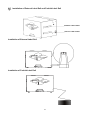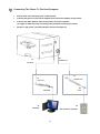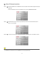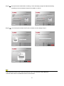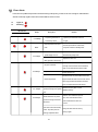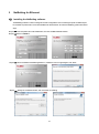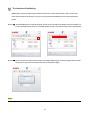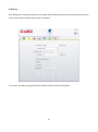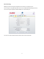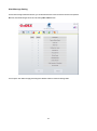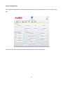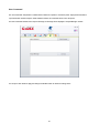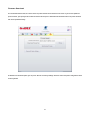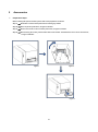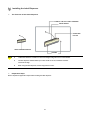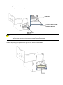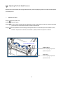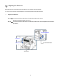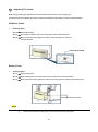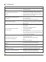
1
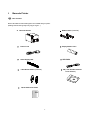
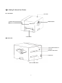
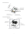
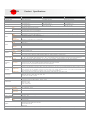
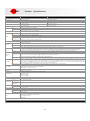
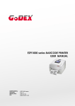
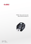
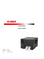
USER MANUAL BP500L SERIES Version : Rev.A Issue Date : 2015.04 P/N : 920-016411-00 CONTENTS 1 2 Barcode Printer ................................................................................................................................................................................. 1 1-1 Box Content................................................................................................................................................................................. 1 1-2 Getting To Know Your Printer .................................................................................................................................................... 2 Printer Setup...................................................................................................................................................................................... 4 2-1 Open The Printer Cover .............................................................................................................................................................. 4 2-2 Open The Printing Mechanism ................................................................................................................................................... 5 2-3 Loading The Ribbon.................................................................................................................................................................... 6 2-4 Loading The Label Roll ............................................................................................................................................................... 8 2-5 Installing The Label Supply Hub .............................................................................................................................................. 10 2-6 Preparing For Tag Printing ....................................................................................................................................................... 11 2-7 Installation of External Label Roll and Fanfold Label Roll...................................................................................................... 12 2-8 Connecting The Printer To The Host Computer ...................................................................................................................... 13 2-9 Wizard CD Standard Installation .............................................................................................................................................. 14 2-10 Wizard CD Other Choice Installation ..................................................................................................................................... 17 3 4 5 Operation Panel ............................................................................................................................................................................... 20 3-1 LED Operation Panel................................................................................................................................................................. 20 3-2 Label size calibration and Self Test Page ................................................................................................................................ 21 3-3 Error Alerts ................................................................................................................................................................................ 22 NetSetting for Ethernet ................................................................................................................................................................... 23 4-1 Installing the NetSetting software ............................................................................................................................................ 23 4-2 The Interface of NetSetting ....................................................................................................................................................... 25 Accessories ..................................................................................................................................................................................... 32 5-1 Installing the Label Dispenser .................................................................................................................................................. 33 5-2 Installing The Cutter.................................................................................................................................................................. 38 5-2-1 Installing The Guillotine Cutter ........................................................................................................................................... 38 5-2-2 Installing The Rotary Cutter ................................................................................................................................................ 42 6 Maintenance And Adjustment ........................................................................................................................................................ 46 6-1 Cleaning The Print Head ........................................................................................................................................................... 46 6-2 Adjusting The Print Head Pressure.......................................................................................................................................... 47 6-3 Adjusting The Print Line ........................................................................................................................................................... 48 6-4 Adjusting The Cutter ................................................................................................................................................................. 49 6-5 Troubleshooting ........................................................................................................................................................................ 50 APPENDIX SAFETY INSTRUCTIONS Please read the following instructions carefully. Keep the equipment away from humidity. Before you connect the equipment to the power outlet, please check the voltage of the power source. Make sure the printer is off before plugging the power connector into the power jack. It is recommended that you connect the printer to a surge protector to prevent possible transient overvoltage damage. Be careful not to get liquid on the equipment to avoid electrical shock. For safety and warranty reasons, ONLY qualified service personnel should open the equipment. Do not repair or adjust energized equipment under any circumstances. CAUTION Danger of explosion if battery is incorrectly replaced. Replace only with the equivalent type recommended by the manufacturer. Dispose of used batteries according to the manufacturer’s instructions. Only use with designated power supply adapter model. Changes or modifications not expressly approved by the party responsible for compliance could void the user's authority to operate the equipment. Specifications are subject to change without notice 1 Barcode Printer 1-1 Box Content Please check that all of the following items are included with your printer. (Package content and Logo style may vary per region。) Ribbon Hubs ( set of 2 ) Barcode Printer Power Cord Empty Ribbon Core Label Supply Hub USB Cable Label Guide Plates ( set of 2 ) CD ( with QLabel software / user manual ) Quick Reference Guide 1 1-2 Getting To Know Your Printer Front View TOP COVER LED INDICATOR VIEWING WINDOW 之 POWER BUTTON FEED BUTTON Rear View FRONT COVER AUTO-CALIBRATION BUTTON USB PORT EXTERNAL LABEL INSERT POWER JACK FAN-FOLD LABEL INSERT 之 2 Open The Printer Cover LABEL SUPPLY MODULE - LABEL SUPPLY HUB - LABEL GUIDE PLATES RIBBON FEED MECHANISM RIBBON HUB EMPTY RIBBON CORE ADJUSTMENT SCREW ( LEFT ) ADJUSTMENT SCREW ( RIGHT ) Screw for adjusting the print head pressure Open The Printing Mechanism Screw for adjusting the print head pressure RELEASE CATCH ( LEFT ) RELEASE CATCH ( RIGHT ) PRINTING MECHANISM RIBBON SUPPLY HUB ADJUSTMENT SCREW LABEL GUIDE ( RIGHT ) PLATEN LABEL GUIDE ( LEFT ) LABEL SENSOR (Movable) 3 2 Printer Setup 2-1 Open The Printer Cover Pressing The Cover Open Buttons Place the printer on a flat surface. Open the printer cover by pressing the release buttons on both sides of the printer housing and lift the cover. 4 2-2 Open The Printing Mechanism Pressing The Release Catches Release and lift the printing mechanism. RELEASE CATCH (LEFT) Lift the printing mechanism RELEASE CATCH (RIGHT) Pressing Pressing 5 2-3 Loading The Ribbon A New Ribbon Module Installation Place the new ribbon on the hub which forms a ribbon supply hub. Place on the hub RIBBON SUPPLY HUB RIBBON HUB NEW RIBBON Place the empty ribbon core on the hub which forms a ribbon rewind hub. Place on the hub RIBBON FEED MODULE RIBBON HUB NEW RIBBON Stick the ribbon supply hub on the ribbon rewind hub and wind the rewind hub 2~3 circles. Wind the ribbon around the core 6 Install The Ribbon On The Printer Place the ribbon supply hub at the back of the printing mechanism. Insert into the printing mechanism Pass the ribbon supply hub under the print head. Insert the ribbon rewind hub on the ribbon feed mechanism. Close the printing mechanism, making sure that it clicks into place. Place on the printing mechanism Wind to the back RIBBON FEED MECHANISM 7 2-4 Loading The Label Roll A New Label Roll Module Installation Place the label stock on the label supply hub, attach the guide plates to the label stock holder. LABEL STOCK Place on the ribbon hub LABEL SUPPLY HUB LABEL GUIDE PLATES Install The Label Roll Module On The Printer Step.01 Press the release catches to lift the printing mechanism and Pass the labels through the label guides up to the tear-off plate. Adjust the label guides to the label width Through the label guides LABEL GUIDES 8 Step.02 Close the printing mechanism. Close the printing mechanism Step.03 Install The Label Roll Module On The Printer Place the label stock into into the printer as the direction of the arrows. 9 2-5 Installing The Label Supply Hub 1" Cores Installing the label supply hub for 1" cores. 1.5" Cores Installing the label supply hub for 1.5" cores. 10 2-6 Preparing For Tag Printing In tag printing, the tag hole indicates the height of a label. During adjustment, the sensor must therefore be positioned directly below the tag hole as shown in the illustration. The tag hole should be at least 3 mm in diameter to ensure correct functioning. SENSOR POSITION 11 2-7 Installation of External Label Roll and Fanfold Label Roll EXTERNAL LABEL INSERT FAN-FOLD LABEL INSERT Installation of External Label Roll Installation of Fanfold Label Roll 12 2-8 Connecting The Printer To The Host Computer Please make sure that the printer is switched off. Connect the power cord to the AC adapter and connect the adapter to the printer. Connect the USB / parallel cable to the printer and host computer. (The type of cable may vary according to the products which you purchase.) Switch on the printer. The LED indicator should now lights up. B1 A1 POWER SLOT USB PORT B1 A1 POWER JACK USB PORT A2 B2 USB PORT PLUG A2 B2 USB PORT THE SOCKET OF THE WALL 13 2-9 Step.01 Wizard CD Standard Installation Insert the Super Wizard CD in the CD/DVD drive of the host computer and the installation program should pop up automatically. You will see the Welcome screen first. On the Welcome screen, choose “STANDARD INSTALLATION”. Step.02 The wizard will then ask you to make sure your USB and power cables are connected and that the power is turned on. Then click “NEXT”. Step.03 The next screen you will see is, “Install the GoLabel Software and Windows driver”. Click “NEXT” to continue. NOTE * If the Super Wizard program did not run automatically, you can either turn on the “Auto-run” setting for your CD/DVD driver or double-click the icon of CD/DVD driver to run the program manually. 14 Step.04 As the printer driver and GoLabel are installing, a screen will display a progress bar. While downloading completed you will see Installation completed. Click “NEXT” to continue. Step.05 You can also print a test label. If don’t print a test label, the screen display as step 6. Note * If you need more resources, tools or reference documents, you can also find them on Super Wizard CD. Just click “Other Choices” on the Welcome Screen to access the files. 15 Step.06 Once the installation is complete, you can start to make and print labels with GoLabel or through the printer driver. 16 2-10 Step.01 Step.02 Step.03 Wizard CD Other Choice Installation Click “OTHER CHOICES” to next screen and select “PRINTER DRIVERS”. Click “INSTALL SEAGULL SCIENTIFIC WINDOWS DRIVER” to next screen, and click “NEXT”. Select “I accept the terms in the license agreement”, and click ”Next”,then click ”Finish” to step 4. 17 Step.04 The Driver Wizard will guide you through the installation procedure. Select "Install printer drivers" and click “Next”. Step.05 With a USB connection, search models such as the right diagram printer device. Specify your printer model and click ”Next”. Step.06 Enter the printer name (you can use default), then click "Next" to display as right diagram. Click "Finish" button to start installation. 18 Step.07 Driver installation completed. 19 3 Operation Panel 3-1 LED Operation Panel FEED Button When you press the FEED button, the printer moves the label to the defined stop position. If you are using continuous labels, pressing the FEED button will move label stock until you release the button again. If you are using individual labels, pressing the FEED button will move only one label. If the label does not stop at the correct position, please run the auto calibration (See Section 3-2. for the label size calibration function) on the label stock. LED Indicators LED indicator READY Beeps Description Green X STATUS x READY x Standby mode The printer is ready for operation. 2 x 2 beeps 2 x 3 beeps STATUS Status 2 x 4 beeps Red 20 The printer has detected Error mode an error. (See Section 3-3. for Error alerts) 3-2 Label size calibration and Self Test Page The printer can automatically detect and store label height. That means the host computer does not need to transmit the label height to the printer. And the self-test function lets you check whether the printer is functioning normally. Here is how you run the label size calibration and self test. Step.01 Check that the label stock is loaded correctly. Step.02 Switch off the printer. Step.03 Switch the printer on again, keeping the FEED button pressed. When the READY LED starts to flash red and the STATUS LED lights up orange, release the FEED button. The printer will now measure the label stock and store the label height Step.04 Once the printer has successfully measured the label stock, it will print a self-test label. The contents of a self-test printout are listed below. (The data below is for reference only, actual result may vary according to each situation.) Model & Version USB ID setting Serial port setting Number of forms Number of graphics Number of fonts Number of Asian fonts Number of Databases Number of Scalable fonts Free memory Speed, Density, Ref. Point, Print direction size Label width, Form length, Stop position Cutter, Label Dispenser, Mode Sensor Setting Code Page 21 3-3 Error Alerts In the event of a problem that prevents normal functioning of the printer, you will see an error message on LED indicators and hear some beep signals. Please refer to below table for the error alerts. Light on Flashing LED indicator Beeps READY Solution Description STATUS 2 x 4 beeps The printing mechanism is Open the print mechanism and close not correctly closed. it again. High temperature at the print None head. Once the print head has cooled down, the printer switches to standby mode. No ribbon is installed and the Make sure that the printer is set to printer displays an error. direct thermal printing mode. 2 x 3 beeps The ribbon is finished or the Replace the ribbon roll. label upply hub is not moving. Make sure that the label sensor is positioned No paper is detected correctly. If the sensor still does not detect the paper, run the auto-detection function again. 2 x 2 beeps Paper is finished. Replace the label roll. Possible reasons: the print medium has become Printer feed problem. trapped around the rubber roll; the sensor cannot detect a gap or black mark between the labels; there is no paper. Please reset the sensor. The memory is full. The printer Delete unnecessary data or install 2 x 3 beeps prints the message "File System additional memory. full". Use the "~X4" command to print all Unable to find file. The printer files. Then check whether the files 2 x 2 beeps prints the message "File Name exist and whether the names are Not found". correct. A file of the same name already Change the name of the file and try exists. The printer prints the storing it again. message "Duplicate Name". 22 4 NetSetting for Ethernet 4-1 Installing the NetSetting software The NetSetting software is used to manage the network configurations when connecting the printer via Ethernet port. It is available on product CD or can be downloaded from official website. To install the NetSetting, please follow below steps. Step.01 Insert the product CD in the CD/DVD drive, and click “OTHER CHOICES” buttom. Step.02 Select “ETHERNET”. Step.03 Click "Install Ethernet NetSetting Software", installation screen as right diagram, click "Next". Step.04 Specify the “Installation Folder", then click ”Next” to installing. 23 Step.05 Once the installation is completed, you will see the NetSetting icon on your desktop as right diagram. 24 4-2 The Interface of NetSetting GoDEX printer can also be used through a network connection (as a remote network printer), make sure the printer connected to the Internet and the power cord, you can use the Interface of NetSetting to search connected network printers. Step.01 Click the NetSetting icon to start the program, you will see the start page as left diagram. Click the magnifier icon to search the Godex printers which are connected via Ethernet port in you network environment (as right diagram). Step.02 There are six tabs on the top of interface which can configure different types of network settings. But for the data security reason, you need correct password to enter the configuration pages. NOTE * The default password is “1111”, you can change the password later from the “IP Setting” tab. 25 IP Setting The IP Setting tab can change the printer name, Port number, Gateway setting and the password for configuring the printer. You can also set the printer’s IP address ether by DHCP or by Static IP. You can press “Set” button to apply the settings and “ReGet” button to refresh the setting values. 26 Alert Path Setting NetSetting will send the alert messages to designated mail account when the error happened on printer. The alert messages are sent by SMTP (Simple Mail Transfer Protocol) or SNMP (Simple Network Management Protocol). You can set or change the configurations of SMTP and SNMP on this “Alert Path Setting” tab. You can press “Set” button to apply the settings and “ReGet” button to refresh the setting values. 27 Alert Message Setting For the alert message notification function, you can decide which error cases need to be sent out to the operator. Moreover, the alert messages can be set to be sent by SMTP, SNMP or both. You can press “Set” button to apply the settings and “ReGet” button to refresh the setting values. 28 Printer Configuration Set or change the configurations of connected printer. Most of key settings for the printer operation can be done by this setting page. You can press “Set” button to apply the settings and “ReGet” button to refresh the setting values. 29 User Command The “User Command” tab provides a communication interface for operator to control the printer. Input printercommands in "Input Command" window and press “Send Command” button, the commands will be sent to the printer. For some commands that will return response message, the message will be displayed in "Output Message" window. You can press “Set” button to apply the settings and “ReGet” button to refresh the setting values. 30 Firmware Download On “Firmware Download” tab, the current version of printer firmware will be showed on the screen. If you need to update the printer firmware, just specify the file location of firmware file and press “Start Download Firmware”button. The printer firmware then can be updated remotely. In addition to the firmware update, you can press “Recover To Factory Settings” button to restore the printer configurations back to factory default. 31 5 Accessories Preparation Steps Before installing the optional modules, please make some preparations as follows. Step.01 Remember to switch off the printer before installing any module. Step.02 Place the printer upside down, as figure 2 indicates. Step.03 Remove two screws on the front of the printer base, as figure 2 indicates. Step.04 After removing the screws, pull the bottom base cover forward. The bottom base cover can be removed now, as figure 3 indicates. Figure 2 Figure 1 Figure 3 32 5-1 Installing the Label Dispenser The Overview of the Label Dispenser CONNECT CABLE OF LABEL DISPENSER PAPER SENSOR PAPER FEED ROLLER LABEL DISPENSER MODULE SCREWS NOTE A label liner thickness of 0.006 mm ± 10% and a weight of 65 g/m2 ± 6% are recommended. The label dispenser will take labels up to a max. width of 110 mm, and labels should be at least 25 mm high. When using the label dispenser, set the stop position to 9 mm. Preparation Steps Please complete the preparation steps before installing the label dispenser. 33 Installing The Label Dispenser Connect the dispenser cable to the lower jack. LOWER JACK CONNECT CABLE OF LABEL DISPENSER MODULE NOTE The printer must be switched off, or the motherboard may be damaged! There are 2 jacks : the lower jack is for the dispenser, the upper jack for the cutter. Install the dispenser by pressing down first its right-hand side and then its left-hand side. LEFT-HAND SIDE RIGHT-HAND SIDE LABEL DISPENSER MODULE 34 Secure the dispenser using the screws provided for this purpose. Locking Locking SCREWS Install The Label Roll Module On The Printer Pass the paper through the guides. Through the label guides LABEL GUIDES 35 Remove the first labels from the liner, so you can pull the liner through the guides. THE PAPER FEED ROLLER OF PRINTER PLATEN Tear a label THE FIRST LABEL Pass the label stock through the printer as shown in the illustration on the right. LABEL LINER THE PAPER FEED ROLLER OF LABEL DISPENSER MODULE THE PAPER LABEL STOCK FEED ROLLER OF PRINTER 36 Close the label dispenser and the print mechanism. The installation is completed now. Close Press the FEED button to feed the label. The label will be peeled from the liner while it passes through the label dispenser. Note There is a paper sensor on the Label Dispenser module. It will stop the printing if it is covered by label. Remove the last printed label and the printer will then continue to print next label. PAPER SENSOR Remove the label Press the FEED key LABEL 37 LINER 5-2 Installing The Cutter 5-2-1 Installing The Guillotine Cutter The Overview Of The Guillotine Cutter CONNECT CABLE OF GUILLOTINE CUTTER MODULE GUILLOTINE CUTTER MODULE SCREWS NOTE Remember to switch off the printer before installing the guillotine cutter. Do not use to cut adhesive labels! Glue residue will be left on the cutter blade and impair its functioning. You can cut paper with a max. width of 116 mm, and The cutter has a blade life of 400,000 cuts when using paper liner which is 250μm thick and 3 inches wide. Labels should be at least 30 mm high to ensure correct functioning of the cutter. SUGGESTION With the cutter installed, set the stop position to 30, or the E value to 30. Before installing the cutter module, remove the cutter cover as shown in the illustration. Preparation Steps Please complete the preparation steps before installing the label dispenser. 38 CONNECT CABLE OF GUILLOTINE CUTTER MODULE UPPER JACK NOTE The printer must be switched off, or the motherboard may be damaged. There are 2 jacks : the lower jack is for the dispenser, the upper jack for the cutter. Secure the cutter using the screws provided for this purpose. Locking Locking SCREWS 39 Secure the cutter cover using the screws provided for this purpose. Locking Locking SCREWS Place the cutter cover Pass the labels through the guides. Close the printing mechanism. Through the label guides Through the cutter module LABEL GUIDES 40 To finish, press the FEED button to set the label position. Press the FEED button NOTE We advise against using inside wound label stock. 41 5-2-2 Installing The Rotary Cutter The Overview Of The Rotary Cutter ROTARY CUTTER MODULE NOTE Remember to switch off the printer before installing the rotary cutter. Do not use to cut adhesive labels! Glue residue will be left on the cutter blade and impair its functioning. The cutter has a blade life of 500,000 cuts when using paper weighing 160 g/m², and of 250,000 cuts when using paper weighing 200 g/m². Labels should be at least 30 mm high. SUGGESTION With the cutter installed, set the stop position to 30, and the E value to 30. 42 Installation of the rotary cutter CONNECT CABLE OF ROTARY CUTTER MODULE UPPER JACK NOTE Step.01 The printer must be switched off, or the motherboard may be damaged! There are 2 jacks : the lower jack is for the dispenser, the upper jack for the cutter. Install the cutter by pressing down first its left-hand side and then its right-hand side. 43 Step.02 Secure the cutter using the screws provided for this purpose. Locking Locking Step.03 Once you have secured the cutter with the screws, fold it back in again. Fold cutter back in again 44 Step.04 Pass the labels through the guides and close the printing mechanism. Through the label guides Through the cutter LABEL GUIDES module Step.05 To finish, press the FEED button to set the label position. Press the FEED Button NOTE We advise against using inside wound label stock. 45 6 Maintenance And Adjustment 6-1 Cleaning The Print Head Dirt on the print head or ribbon, or glue residue from the label stock may result in inadequate print quality. The printer cover must therefore always be closed during printing. Keeping dirt and dust away from the paper or labels ensures a good print quality and a longer lifespan of the print head. PRINT HEAD Cleaning Steps Step.01 Switch off the printer. Step.02 Open the printer cover. Step.03 Release the printing mechanism and lift it. To clean the print head Step.04 Remove the ribbon 6-2 Step.05 To remove any label residue or other dirt from the Turn the adjustment print head (see blue arrow), please use a soft screws lint-free cloth dipped in alcohol. SCREW ( RIGHT ) Screw for adjusting the NOTE print head pressure on The print head should be cleaned once a week. Please make sure that there are no metal fragments or other hard particles on the soft clothright usedside to SCREW ( clean the print head. 46 6-2 Adjusting The Print Head Pressure When printing on special media (with varying material thickness), the print quality may suffer. You will then need to adjust the print head pressure. Adjustment Steps Step.01 Open the printer cover. Step.02 Remove the ribbon. Step.03 Use a screw driver and slowly turn the adjustment screws for the print head to increase or reduce the print head pressure. Do not screw it hard, otherwise the machine will be broken. Step.04 Turn the adjustment screws according to actual position which is unsuccessful printed. Turn towards + (Plus) indicates : The pressure is increased;Turn towards – (Minus) indicates: The pressure is reduced. Turn the adjustment screws SCREW ( RIGHT ) Screw for adjusting the print head pressure on right side SCREW ( LEFT ) Screw for adjusting the print head pressure on left side 47 6-3 Adjusting The Print Line When the print line is incorrectly set, the print quality on one side of the medium may suffer. In such a case, the print line must be adjusted so it is positioned parallel to the paper feed roller. Adjustment Methods Step.01 To move the print head in direction B as indicated by the blue arrow, turn the adjustment wheel anticlockwise (see arrow 1). Step.02 To move the print head in direction B as indicated by the blue arrow, turn the adjustment wheel clockwise (see arrow 2). Turn the adjustment wheel Direction-A ADJUSTMENT WHEEL Direction-B PRINT HEAD 48 6-4 Adjusting The Cutter While using the cutter, paper jams may occur. Please follow the below steps to clean the paper jam. A socket head screw for adjusting the cutter is located on the bottom of cutter module, as shown in below illustration. Guillotine Cutter Cleaning Steps Step.01 Switch off the printer. Step.02 Use a Philips screwdriver to turn the socket head screw and release the knife. Step.03 When you have cleared the paper jam, switch on the printer again. The cutter will automatically reset. SOCKET HEAD SCREW Rotary Cutter Cleaning Steps Step.01 Switch off the printer Step.02 Switch off the printer and use a hex key to turn the socket head screw anticlockwise. Step.03 When you have cleared the paper jam, switch on the printer again. The cutter will automatically reset. Adjusting position of the cutter NOTE Labels should be at least 30 mm high to ensure correct functioning of the cutter. 49 6-5 Troubleshooting Problem The printer is switched on but the display does not Solution Check the power supply.。 Check the software settings (driver settings) or command codes. One or both LEDs light up red and printing is Look for the error alert in the table in Section 3-3 Error alerts . interrupted. Check whether the cutter is functioning normally and whether it is light up. cutting at all. (Only if a cutter is installed.) Please make sure that the label stock is loaded the right way up and The label stock passes through the printer but no that it is suitable material. image is printed. Please make sure that the ribbon is loaded correctly. Clear the paper jam. Remove any label material left on the thermal The label stock jams during printing. print head and clean the print head using a soft lint-free cloth dipped in alcohol. Check the thermal print head for dust or other dirt (label material or ribbon residue). Check for errors in the application software. There is no printed image on part of the label Check the ribbon for wrinkles. or the image is blurred. Check the power supply. Run a self test (Section 3-2 ) and check the test print pattern to see whether the print head prints over the entire width of the medium. The printed image is positioned incorrectly Check the quality of the print medium. Run the Label size calibration function. (Section 3-2) Check the label height setting. Check whether there is paper or dust covering the or a label is missed out during printing. sensor. Check the paper guide settings. Check whether the label stock is positioned straight. Check whether the label is more than 0.2 mm thick. When using the cutter, the labels are not fed Check whether the cutter has been correctly installed. through or cut off incorrectly. Check whether the paper guides are functioning correctly. Check whether there is dust on the label dispenser. Check whether the label stock is positioned correctly. The cutter does not cut off the labels in a straight line. The cutter does not cut off the labels completely. The label dispenser is not functioning normally. NOTE If any problems occur that are not described here, please contact your dealer. 50 APPENDIX Product G500 Series Model Name Print Method Resolution (dpi) Print Speed (ips) Print Width Appendix_ Print Length Processor Memory Flash SDRAM Sensor Type Bitmap fonts TTF Fonts Bitmap Fonts Download Fonts Asian Fonts TTF Fonts Barcodes 1-D Barcodes 2-D Barcodes Code Pages Graphics Interfaces Control Panel Real Time Clock Power Operation temperature Environment Storage temperature Operation Humidity Storage Agency Approvals Length Dimension Height Width BP500L BP520L BP530L Thermal Transfer / Direct Thermal 203 dpi (8 dots/mm) 203 dpi (8 dots/mm) 300 dpi (12 dots/mm) 5IPS (127 mm/s) 7 IPS (177 mm/s) 5IPS (127 mm/s) 108 mm (4.25”) 108 mm (4.25 ”) 105.7mm (4.16") Min. 4mm (0.16”)**; Min. 4 mm (0.16 ”)** Min. 4 mm (0.16 ”)** Max. 1727mm (68”) Max. 1727 mm (68 ”) Max. 762 mm (30 ”) 32 bit RISC CPU 128 MB Flash (60MB for user storage) 32 MB Fixed transmissive sensor, central aligned Adjustable reflective sensor (full range) Continuous form, gap labels, black mark sensing, and punched hole; label length set by auto sensing or programming Min. 25.4 mm (1 ”) ~ Max. 118 mm(4.64 ”) Min. 0.06 mm (0.0024 ”) ~ Max. 0.25 mm (0.01 ”) roll Max. 152 mm (6 ”) Types Width Thickness Media Label diameter Core diameter Types Length Width Ribbon Ribbon roll diameter Core diameter Printer Language Label design software Software Driver DLL Resident Fonts Specifications 25.4 mm (1 ”)、38.1 mm (1.5 ”)、76.2 mm (3”) Wax、Wax/resin、resin 300 m (981 “) 30 mm (1.18 “) ~ 110 mm (4.33 “) 68 mm (2.67 ”) 25.4 mm (1 ”) EZPL、GEPL、GZPL,auto switch GoLabel (for EZPL only) Windows 2000 / XP / VISTA / Windows 7 / Windows 8.1 Win CE, .NET, Andriod, Windows Mobile, Windows 2000 / XP / VISTA / Windows 7 / Windows 8.1 Bitmap fonts 6、8、10、12、14、18、24、30、16x26 and OCR A&B 90°、180°、270° rotatable, single characters 90°、180°、270° rotatable. 8 times expandable in horizontal and vertical directions. CG Triumvirate™ (Bold / Italic / Underline),0°、90°、180°、270° rotatable,single characters 90°, 180°, 270° rotatable。 Bitmap fonts 90°, 180°, 270° rotatable, single characters 90°, 180°, 270° rotatable。 16x16, 24x24. Traditional Chinese (BIG-5), Simplified Chinese(GB2312), Japanese(S-JIS), Korean (KS-X1001) Bitmap fonts 90°, 180°, 270° rotatable, single characters 90°, 180°, 270° rotatable. Bitmap fonts 8 times expandable in horizontal and vertical directions. Bitmap fonts 90°, 180°, 270° rotatable, single characters 90°, 180°, 270° rotatable。 Code 39, Code 93, EAN 8 /13 (add on 2 & 5), UPC A/E (add on 2 & 5), I 2 of 5 & I 2 of 5 with Shipping Bearer Bars, Codabar, Code 128 (subset A, B, C), EAN 128, RPS 128, UCC 128, UCC/EAN-128 K-Mart, Random Weight, Post NET, ITF 14, China Postal Code, HIBC, MSI, Plessey, Telepen, FIM, GS1 DataBar, German Post Code, Planet 11 & 13 digit, Japanese Postnet, I 2 of 5 with human readable check digit, Standard 2 of 5, Industrial 2 of 5, Logmars, Code 11, Code 49 and Cadablock PDF417, Datamatrix code, MaxiCode, QR code, Micro PDF417, Micro QR code 以及 Aztec code. CODEPAGE 437, 850, 851, 852, 855, 857, 860, 861, 862, 863, 865, 866, 869, 737 WINDOWS 1250, 1251, 1252, 1253, 1254, 1255, 1257 Unicode UTF8、UTF16BE、UTF16LE Resident graphic file types are BMP and PCX, other graphic formats are downloadable from the software USB Device port (B-Type) Two groups of two-color LED indicator:Ready、Status Calibration button Control key : FEED Power on/off button Standard Switching power 100-240VAC, 50-60Hz input 41°F ~ 104°F (5°C ~ 40°C) -4°F ~ 122°F (-20°C ~ 50°C) 30 % ~ 85 %,non-condensing. 10 % ~ 90 %,non-condensing. CB、CCC、cUL 320 mm (12.5 ”) 220 mm (8.7 ”) 275 mm (10.8 ”) Cutter Label dispenser with label sensor module Options External label rewinder Wireless LAN * Specifications are subject to change without notice. All company and/or product names are trademarks and/or registered trademarks of their respective owners. 51 APPENDIX 機種 Print Method Resolution (dpi) Print Speed (ips) Print Width Print Length Processor Memory Flash SDRAM Sensor Type Download Fonts Bitmap fonts TTF Fonts Bitmap Fonts Asian Fonts 1-D Barcodes 2-D Barcodes Code Pages Graphics Interfaces Control Panel Real Time Clock Power Operation temperature Environment Storage temperature Operation Humidity Storage Agency Approvals Length Dimension Height Width BP520L (DT) Direct Thermal 203 dpi (8 dots/mm) 203 dpi (8 dots/mm) 5IPS (127 mm/s) 7 IPS (177 mm/s) 108 mm (4.25”) 108 mm (4.25 ”) Min. 4mm (0.16”)**; Min. 4 mm (0.16 ”)** Max. 1727mm (68”) Max. 1727 mm (68 ”) 32 bit RISC CPU 128 MB Flash (60MB for user storage) 32 MB Fixed transmissive sensor, central aligned Adjustable reflective sensor (full range) Continuous form, gap labels, black mark sensing, and punched hole; label length set by auto sensing or programming Min. 25.4 mm (1 ”) ~ Max. 118 mm(4.64 ”) Min. 0.06 mm (0.0024 ”) ~ Max. 0.25 mm (0.01 ”) roll Max. 152 mm (6 ”) TTF Fonts Barcodes Specifications BP500L (DT) Types Width Thickness Media Label diameter Core diameter Printer Language Label design software Software Driver DLL Resident Fonts Product 25.4 mm (1 ”)、38.1 mm (1.5 ”)、76.2 mm (3”) EZPL、GEPL、GZPL,auto switch GoLabel (for EZPL only) Windows 2000 / XP / VISTA / Windows 7 / Windows 8.1 Win CE, .NET, Andriod, Windows Mobile, Windows 2000 / XP / VISTA / Windows 7 / Windows 8.1 Bitmap fonts 6、8、10、12、14、18、24、30、16x26 and OCR A&B 90°、180°、270° rotatable, single characters 90°、180°、270° rotatable. 8 times expandable in horizontal and vertical directions. CG Triumvirate™ (Bold / Italic / Underline),0°、90°、180°、270° rotatable,single characters 90°, 180°, 270° rotatable。 Bitmap fonts 90°, 180°, 270° rotatable, single characters 90°, 180°, 270° rotatable。 16x16, 24x24. Traditional Chinese (BIG-5), Simplified Chinese(GB2312), Japanese(S-JIS), Korean (KS-X1001) Bitmap fonts 90°, 180°, 270° rotatable, single characters 90°, 180°, 270° rotatable. Bitmap fonts 8 times expandable in horizontal and vertical directions. Bitmap fonts 90°, 180°, 270° rotatable, single characters 90°, 180°, 270° rotatable。 Code 39, Code 93, EAN 8 /13 (add on 2 & 5), UPC A/E (add on 2 & 5), I 2 of 5 & I 2 of 5 with Shipping Bearer Bars, Codabar, Code 128 (subset A, B, C), EAN 128, RPS 128, UCC 128, UCC/EAN-128 K-Mart, Random Weight, Post NET, ITF 14, China Postal Code, HIBC, MSI, Plessey, Telepen, FIM, GS1 DataBar, German Post Code, Planet 11 & 13 digit, Japanese Postnet, I 2 of 5 with human readable check digit, Standard 2 of 5, Industrial 2 of 5, Logmars, Code 11, Code 49 and Cadablock PDF417, Datamatrix code, MaxiCode, QR code, Micro PDF417, Micro QR code 以及 Aztec code. CODEPAGE 437, 850, 851, 852, 855, 857, 860, 861, 862, 863, 865, 866, 869, 737 WINDOWS 1250, 1251, 1252, 1253, 1254, 1255, 1257 Unicode UTF8、UTF16BE、UTF16LE Resident graphic file types are BMP and PCX, other graphic formats are downloadable from the software USB Device port (B-Type) Two groups of two-color LED indicator:Ready、Status Calibration button Control key : FEED Power on/off button Standard Switching power 100-240VAC, 50-60Hz input 41°F ~ 104°F (5°C ~ 40°C) -4°F ~ 122°F (-20°C ~ 50°C) 30 % ~ 85 %,non-condensing. 10 % ~ 90 %,non-condensing. CB、CCC、cUL 320 mm (12.5 ”) 220 mm (8.7 ”) 275 mm (10.8 ”) Cutter Label dispenser with label sensor module Options External label rewinder Wireless LAN * Specifications are subject to change without notice. All company and/or product names are trademarks and/or registered trademarks of their respective owners. 52