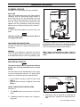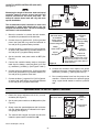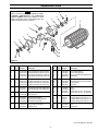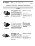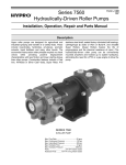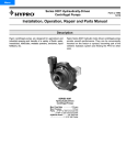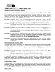
1
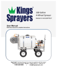
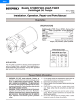
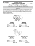
Menu
4000 Series 12-Volt
Electric-Driven Roller Pumps
& 2530-0057 Speed Controller
Form L-0130R
6/11, Rev. B
Installation, Operation, Repair, and Parts Manual
Description
Hypro Roller Pumps are designed for agricultural and
industrial transfer of a variety of fluids and chemicals.
The 4001 Series maximizes flow and the 4101 Series
maximizes pressure. Both are coupled to 12-volt DC
motors that are driven by a standard 12-volt battery.
These systems are ideal for bulk chemical transfer, fertilizer placement, herbicide banding, nitrogen side
dressing, and orchard and cattle spraying.
The E2H Models have specially designed motors for
situations where higher pressure is desired.
The 2530-0057 Speed Controller allows smooth
variable speed operation to accurately set pressures for
controlled application rates. Optional switched leads are
included for a boom control solenoid valve. Maximum
output is 25 amps. Refer to the performance charts for
maximum performance at 25 amps.
4000 Series 12-Volt
Electric-Driven Roller Pump
2530-0057
Speed Controller
Model 4101N-EH and 4101XL-EH, Model 4101N-E2H and 4101XL-E2H
Model 4001N-EH and 4001XL-EH, Model 4001N-E2H and 4001XL-E2H
12-Volt Roller Pump and Motor Unit
Maximum Flow:
4101N-EH and 4101XL-EH . . . . . . . . . . . . . . . . . . . . . . . . . . . . . . . . . . . . . . . . . . . . . . . . . . . . 7.5 gpm [28.4 lpm]
4101N-E2H and 4101XL-E2H . . . . . . . . . . . . . . . . . . . . . . . . . . . . . . . . . . . . . . . . . . . . . . . . . . 5.9 gpm [22.3 lpm]
4001N-EH and 4001XL-EH . . . . . . . . . . . . . . . . . . . . . . . . . . . . . . . . . . . . . . . . . . . . . . . . . . . 10.4 gpm [39.4 lpm]
4001N-E2H and 4001XL-E2H . . . . . . . . . . . . . . . . . . . . . . . . . . . . . . . . . . . . . . . . . . . . . . . . . . 9.9 gpm [37.5 lpm]
Maximum PSI:
4101N-EH and 4101XL-EH . . . . . . . . . . . . . . . . . . . . . . . . . . . . . . . . . . . . . . . . . . . 50 psi [3.45 BAR] continuous
4101N-E2H and 4101XL-E2H . . . . . . . . . . . . . . . . . . . . . . . . . . . . . . . . . . . . . . . . . 90 psi [6.20 BAR] continuous
4001N-EH and 4001XL-EH . . . . . . . . . . . . . . . . . . . . . . . . . . . . . . . . . . . . . . . . . . . 30 psi [2.07 BAR] continuous
4001N-E2H and 4001XL-E2H . . . . . . . . . . . . . . . . . . . . . . . . . . . . . . . . . . . . . . . . . 50 psi [3.45 BAR] continuous
Ports: . . . . . . . . . . . . . . . . . . . . . . . . . . . . . . . . . . . . . . . . . . . . . . . . . . . . . . . . . . . . . . . . . . . . . . . . . . .
3/4” NPT inlet
3/4” NPT outlet
Max. Inlet Vacuum . . . . . . . . . . . . . . . . . . . . . . . . . . . . . . . . . . . . . . . . . . . . . . . . . . . . . . . . . . . . . . . 10” Hg [0.7 BAR]
General Safety Information
The following attention notices are used to notify and
advise the user of this product of procedures that may
be dangerous to the user or result in damage to the
product.
• Use a pressure relief device on the discharge
side of the pump to prevent damage from pressure buildup when the pump discharge is
blocked or otherwise closed and the power
source is still running.
Notes are used to notify of installation, operation, or
maintenance information that is important but not
safety related.
• Do not pump at pressures higher than the maximum recommended pressure.
• Do not pump liquids at temperatures higher than
the recommended maximum temperature.
Caution is used to indicate the presence of a hazard, which will or can cause minor injury or property
damage if the notice is ignored.
• Disconnect the power before servicing the pump.
• Release all pressure within the system before
servicing any component.
Warning denotes that a potential hazard exists and
indicates procedures that must be followed exactly
to either eliminate or reduce the hazard, and to
avoid serious personal injury, or prevent future
safety problems with the product.
• Drain all liquids from the system before servicing
any component.
• Check hoses for weak or worn condition before
each use. Make certain that all connections are
tight and secure.
Danger is used to indicate the presence of a hazard
that will result in sever personal injury, death, or
property damage if the notice is ignored.
• Periodically inspect the pump and the system
components. Perform routine maintenance as
required.
Do not pump flammable or explosive fluids such as
gasoline, fuel oil, kerosene, etc. Do not use in
explosive atmospheres. The pump should be used
only with fluids that are compatible with the pump
component materials. Failure to follow this notice
can result in severe personal injury, death, and/or
property damage and will void the product warranty.
• Use only pipe, hose, and fittings rated for the
maximum pressure rating of the pump.
• Do not use these pumps for pumping water or
other liquids for human or animal consumption.
• The sound pressure level of the pump is 82 dBA.
Observe all safety precautions when operating
the pump within close proximity for extended
periods by wearing hearing protectors. Extended
exposure to elevated sound levels will result in
permanent loss of hearing acuteness, tinnitus,
tiredness, stress, and other effects such as loss
of balance and awareness.
Never use your hand to check the condition of
hydraulic lines or hoses. If hydraulic fluid penetrates the skin, get medical attention immediately.
Failure to proper medical attention may result in
loss of limb or life. The safest way to check
hydraulic lines or hoses is by holding a piece of
cardboard next to the hydraulic line or hose.
Form L-0130R (6/11, Rev. B)
-2-
Installation Instructions
PLUMBING HOOK-UP
See Figure 1 for recommended plumbing installation.
INLET LINE
Use a 3/4'' 2-braid suction hose or 3/4'' pipe to prevent
collapsing. Avoid all unnecessary bends, elbows, or
kinks in the inlet line. The less restrictions in the inlet
line, the better the pump will perform. Avoid loops in the
inlet line. Loops in the inlet line will permit air to be
trapped in the line, preventing the pump from priming.
Make sure all connections are tight and do not leak air.
STRAINER
A strainer should be installed on the inlet side of the
pump.
Check the strainer periodically to ensure that it is
not clogged with debris.
Figure 1
tee should be installed in the inlet line to allow liquid to
be poured into the inlet line to facilitate priming.
Installation of a foot valve is also recommended onto the
inlet line on the bottom of the tank (See Figure 1).
DISCHARGE HOSE AND FITTINGS
Use only hose, pipe, pipe fittings, and accessories that
are rated at or above the maximum operating pressure
of the pump.
PRIMING
This pump is not designed to "self prime" more than 3
ft. [0.9 m] above liquid level. Ideally, the pump should
be located below the tank. If this is not possible, a pipe
Make certain all inlet fittings are tight. Loose or
leaking fittings will decrease the pump’s ability to
prime.
ELECTRICAL HOOK-UP
The motor must be fused to protect the electrical
system. Use a 30 amp slow-blow fuse or circuit
breaker.
The motor lead wires are identified with (+) and (-) tags
on each corresponding lead wire. For proper pump
rotation, the connections should be made as follows:
•
•
ON/OFF Toggle Switch
(rated at 35 amps)
Positive Motor Lead (+) to Positive Power Lead
(Red, +).
Negative Motor Lead (-) to Negative Power Lead
(Black, -).
ON/OFF TOGGLE SWITCH INSTALLATION
See Figure 2.
Figure 2
1. The ON/OFF Switch must be rated at or above 35
amps.
30 amp
Slow-Blow Fuse
or circuit breaker
12-volt
Battery
3. Performance may be improved by shortening the
motor lead wires. Minimize wire length where possible.
2. If additional lead wire is required, use 10 gauge or
larger wire.
Form L-0130R (6/11, Rev. B)
-3-
12 VOLT DC SPEED CONTROLLER (2530-0057)
See Figure 3.
Hypro Model
2530-0057 Speed
Controller
Shortening the length of the motor leads and speed
controller leads to remove excess lead wire will
improve performance and lower amp draw. The
amount to shorten these leads will vary with each
specific installation.
12 Volt
Power
Source
The recommended speed controller to motor lead
connection is solder with shrink tube or wire nut
wrapped with electrical tape. The use of crimp-type
connectors is not recommended.
Leads for
Optional
Solenoid
Valves
Figure 3
1. Mount the controller in a remote but safe location,
accessible, but protected from the elements.
Speed
Adjustment
Dial
Main Power Switch
Circuit Breaker
(35 amp, thermal)
located behind
Pressure Gauge Fitting
2. Connect the red (+) positive 20 ft. [6.09 m] provided
power lead (lead with ring terminals fastened on
one end) to the (+) positive battery terminal.
Pressure Gauge
(0-60 psi [4.1 BAR])
DC Motor
Leads
Battery
Power Leads
3. Connect the black (-) negative 20 ft. [6.09 m] provided power lead (lead with ring terminals fastened on
one end) to the (-) negative battery terminal.
Special
Receptacle
Special
Receptacle
4. Set the controller main power switch to OFF (See
Figure 4).
5. Connect the controller battery leads to the power
leads from the battery, connecting Red (+) to Red
(+) and Black (-) to Black (-). (See Figures 3 and 4.)
Figure 4
Fusible Link
(10 amp fuse)
Optional Solenoid Valve leads (If the
solenoid valve leads are not used,
secure them to the motor leads or
speed controller.)
8. Connect the controller motor leads to the power
leads from the motor, connecting Red (+) to Red (+)
and Black (-) to Black (-). (See Figures 3 and 4.)
6. Connect the red (+) positive 20 ft. [6.09 m] provided
power lead (lead without ring terminals fastened on
one end) to the (+) positive motor lead.
9. Run a small pressure hose from the pump to the
controller. Connect this hose to the pressure gauge
using a pipe thread sealant to ensure a positive
seal.
7. Connect the black (-) negative 20 ft. [6.09 m] provided power lead (lead without ring terminals fastened
on one end) to the (-) negative motor lead.
Operation with 12 Volt DC Speed Controller
1. Rotate the speed adjustment dial fully counter
clockwise (See Figure 5).
Main Power Switch
2. Set the main power switch to the ON position (See
Figure 5).
Speed
Adjustment
Dial
Pressure Gauge
(0-60 psi)
3. Slowly rotate the speed adjustment dial clockwise
until the desired pressure is indicated on the pressure gauge (See Figure 5).
4. The solenoid will energize and open the valve the
instant the power switch is switched to ON.
Figure 5
Form L-0130R (6/11, Rev. B)
-4-
Fertilizer Application (Special Instructions)
Popular uses for the 4101N-E2H include starter fertilizer application for row crop planting. Starter fertilizer is
heavier than water per gallon (approx.1.40 specific
Gravity) and is also more viscous. These two characteristics will affect the performance as compared to
water like herbicide/pesticide applications. Refer to the
Performance Chart on page 6 for examples of performance using 10-34-0 fertilizer.
Liquid fertilizers also have a tendency to cause
gumming if left in the pump. Thoroughly flush the
pump after each use as described in Care of the
Pump.
Care of the Pump
TIGHT PUMP
Before starting the pump, make sure it can be freely rotated by hand.
CORROSION
If the rotor is stuck due to rust or failure to clean the
pump after use, the rotor can be freed by loosening
each endplate bolt one full turn.
A few drops of oil poured into the ports will help
free the rotor.
Using an adjustable wrench, turn the shaft to break the
rotor loose. Keep turning the shaft as the endplate bolts
are alternately and evenly tightened.
FOREIGN OBJECT
If something is lodged in the pump (wire, straw, rust
flake, stick, etc.), the pump will have to be partially disassembled to remove the object. Refer to Hypro Form
L-0100R for disassembly instructions.
LUBRICATION
forced into the ball bearings. Do not plug or inject oil into
these two drain holes. Excessive dripping from these
drain holes indicates seal or shaft wear and these worn
parts must be replaced. Refer to Hypro Form L-0100R
for repair instructions.
This pump is equipped with factory-lubricated ball bearings and requires no further lubrication. Do not allow
kerosene or oil to enter into the ball bearings as this will
wash the grease out of the ball bearings. The two drain
holes under the bearing housings serve to relieve the
pressure behind the bearing seals and prevent any liquid which may get behind the bearing seals from being
AFTER USE PUMP CARE
GUMMING
Gumming or corrosion inside the pump can be prevented by thoroughly flushing the pump with water or a liquid that will neutralize the liquid pumped. For many liquids, a solution of 1 gallon [3.785 liter] of ammonia
mixed with 6 gallons [2.271 liters] of water may be used
as a flushing solution. If the pump has been used for
liquid fertilizer or similar liquids, it should be flushed
after each use.
CORROSION PREVENTION
To prevent corrosion, Hypro recommends:
•
•
Flush the pump with a 50-50 solution of a permanent-type automotive antifreeze containing a rust
inhibitor and water; then plug the pump ports to prevent air from getting into the pump.
•
Cleaning and rust protection should be performed
whenever the pump with be stored for more than
two to three days.
DO NOT:
• Do not use a screwdriver or hammer to force the
pump apart. Follow the Repair Instructions in Hypro
Form L-0100R.
Flush the pump as described in Gumming.
Form L-0130R (6/11, Rev. B)
-5-
•
Do not run the pump dry. Doing so may damage the
roller and seals.
•
Do not pump sandy or gritty liquids. Avoid pumping
solutions containing abrasive material.
•
Do not pump hot liquids (over 140° F. [59.9° C]).
•
Do not pump copper sulphate or corrosive acids
with cast iron, Ni-Resist or XL Series pumps.
Roundup™ type herbicides are only compatible
with XL Series pumps.
Performance
In Water
Volts
12.0
(Battery)
Engine
O ff
13.5
(Alternator)
Engine Running
Model 4101N- EH
and 4101XL- EH
GPM
psi
AMPS
[LPM]
[BAR]
6.3
0
10.0
[23.8]
[0.00]
5
6.0
11.3
[0.34]
[22.7]
5.8
10
12.5
[21.9]
[0.68]
15
5.6
13.7
[1.03]
[21.2]
20
5.4
15.1
[1.38]
[20.4]
25
5.2
16.7
[1.72]
[19.7]
30
5.0
18.6
[2.07]
[18.9]
4.8
35
20.3
[18.2]
[2.41]
40
4.6
22.3
[2.76]
[17.4]
45
4.4
24.1
[3.10]
[16.6]
50
4.2
25.7
[3.45]
[15.9]
psi
GPM
AMPS
[BAR]
[LPM]
0
7.5
10.4
[0.00]
[28.4]
5
7.0
11.7
[0.34]
[26.5]
6.6
10
13.0
[25.0]
[0.68]
15
6.4
14.2
[1.03]
[24.2]
20
6.2
15.8
[1.38]
[23.5]
25
6.0
17.4
[1.72]
[22.7]
30
5.8
19.6
[2.07]
[22.0]
35
5.6
20.9
[2.41]
[21.2]
40
5.4
22.5
[2.76]
[20.4]
45
5.2
224.3
[3.10]
[19.7]
50
5.0
26.1
[3.45]
[18.9]
Model 4101N- E2H
and 4101XL- E2H
GPM
p si
AMPS
[LPM]
[BAR]
0
----[0.00]
10
5.3
8.4
[0.69]
[20.0]
4.8
20
11.8
[18.2]
[1.4]
30
4.65
13.7
[2.1]
[17.60]
40
4.4
16.4
[2.8]
[16.6]
50
4.05
19.6
[3.4]
[15.33]
60
3.65
22.8
[4.1]
[13.82]
3.20
70
25.8
[12.11]
[4.8]
80
3.00
28.9
[5.5]
[43.50]
90
2.75
31.5
[6.2]
[10.41]
100
2.60
34.2
[6.9]
[9.84]
p si
GPM
AMPS
[BAR]
[LPM]
0
----[0.00]
10
5.9
9 .1
[0.69]
[22.3[
5.8
20
11.2
[21.9]
[1.4]
30
5.25
13.9
[2.1]
[19.87]
40
5.0
16.9
[2.8]
[18.9]
50
4.7
19.5
[3.4]
[17.8]
60
4.35
22.7
[4.1]
[16.46]
70
4.0
25.7
[4.8]
[15.1]
80
3.6
29.2
[5.5]
[13.6]
90
3.4
31.9
[6.2]
[12.9]
100
3.2
34.8
[6.9]
[12.1]
[16.4]
4
Form L-0130R (6/11, Rev. B)
-6-
Replacement Parts
When ordering parts, give QUANTITY, PART
NUMBER, DESCRIPTION and COMPLETE
MODEL NUMBER. Reference numbers are used
ONLY to identify parts in the drawing and are
NOT to be used as order numbers.
4
2
13
9
8
1
12
16
5
6
8
9
3
7
11A
14
15
19
18
11
Figure 6
Ref.
No.
Qty.
Req'd
Part
Number
Description
1
1
1
1
1
1
1
1
0100-4001N
0100-4101N
0100-4001X
0100-4101X
2
2
2
2
1
1
1
1
3
3
Ref.
No.
Qty.
Req'd
Part
Number
Description
Body (Ni-Resist) with Std. Seal (4001)
Body (Ni-Resist) with Std. Seal (4101)
Body (Silvercast) with Std. Seal (4001)
Body (Silvercast) with Std. Seal (4101)
8
8
8
9
2
2
2
2
2107-0002
2102-0001
2102-0001T
2000-0010
Viton Seal (Standard)
Buna-N Seal (Optional)
Teflon-Coated Buna-N Seal(Optional)
Ball Bearing
0200-4001N
0200-4101N
0200-4001X
0200-4101X
Endplate (Ni-Resist) Std. Seal (4001)
Endplate (Ni-Resist) Std. Seal (4101)
Endplate (Silvercast) Std. Seal (4001)
Endplate (Silvercast) Std. Seal (4101)
11
11A
12
13
1
1
1
1
2300-0021
6031-0258
1420-0001
2230-0001
Bearing Cover
Name Plate (Specify Pump Model No.)
Locking Collar
Set Screw
1
1
3430-0780
3430-0781
Rotor Assembly (Std. 4001 Ni-Resist & XL)
Rotor Assembly (Std. 4101 Ni-Resist & XL)
14
15
16
16
1
2
1
1
1510-0054
1450-0003
2570-0013
2570-0015
Base
Bumper
Electric Motor (12 vdc, .33 hp) (gold)
Electric Motor (12 vdc, .39 hp) (black)
4
4
1
1
2230-0016
2230-0002
Rotor Set Screw (Silvercast Only)
Rotor Set Screw
5
5
5
4
4
4
1005-0002
1002-0002
1055-0002
Super Rollers (Standard)
Polypropylene Rollers (Optional)
Teflon Rollers (Optional)
17
17
17
17
1
1
1
1
4001N-H
4001XL-H
4101N-H
4101XL-H
Complete Roller Pump Assy (Not Shown)
Complete Roller Pump Assy (Not Shown)
Complete Roller Pump Assy (Not Shown)
Complete Roller Pump Assy (Not Shown)
6
7
1
4
1720-0104
2220-0018
O-ring Gasket for Endplate
Endplate Screw
18
19
2
2
2210-0003
2260-0002
Bolt
Lock Washer
Form L-0130R (6/11, Rev. B)
-7-
Limited Warranty on Hypro/SHURflo Agricultural Pumps & Accessories
Hypro/SHURflo (hereafter, “Hypro”) agricultural products are warranted to be free of defects in material and workmanship under
normal use for the time periods listed below, with proof of purchase.
- Pumps: one (1) year from the date of manufacture, or one (1) year of use. This limited warranty will not
exceed two (2) years, in any event.
- Accessories: ninety (90) days of use.
This limited warranty will not apply to products that were improperly installed, misapplied, damaged, altered, or incompatible with
fluids or components not manufactured by Hypro. All warranty considerations are governed by Hypro’s written return policy.
Hypro’s obligation under this limited warranty policy is limited to the repair or replacement of the product. All returns will be tested
per Hypro’s factory criteria. Products found not defective (under the terms of this limited warranty) are subject to charges paid by the
returnee for the testing and packaging of “tested good” non-warranty returns.
No credit or labor allowances will be given for products returned as defective. Warranty replacement will be shipped on a freight
allowed basis. Hypro reserves the right to choose the method of transportation.
This limited warranty is in lieu of all other warranties, expressed or implied, and no other person is authorized to give any other
warranty or assume obligation or liability on Hypro’s behalf. Hypro shall not be liable for any labor, damage or other expense, nor
shall Hypro be liable for any indirect, incidental or consequential damages of any kind incurred by the reason of the use or sale of
any defective product. This limited warranty covers agricultural products distributed within the United States of America. Other world
market areas should consult with the actual distributor for any deviation from this document.
Return Procedures
All products must be flushed of any chemical (ref. OSHA section 1910.1200 (d) (e) (f) (g) (h)) and hazardous chemicals must be
labeled/tagged before being shipped* to Hypro for service or warranty consideration. Hypro reserves the right to request a Material
Safety Data Sheet from the returnee for any pump/product it deems necessary. Hypro reserves the right to “disposition as scrap”
products returned which contain unknown fluids. Hypro reserves the right to charge the returnee for any and all costs incurred for
chemical testing, and proper disposal of components containing unknown fluids. Hypro requests this in order to protect the environment and personnel from the hazards of handling unknown fluids.
Be prepared to give Hypro full details of the problem, including the model number, date of purchase, and from whom you purchased
your product. Hypro may request additional information, and may require a sketch to illustrate the problem.
Contact Hypro Service Department at 800-468-3428 to receive a Return Merchandise Authorization number (RMA#).
Returns are to be shipped with the RMA number clearly marked on the outside of the package. Hypro shall not be liable for freight
damage incurred during shipping. Please package all returns carefully. All products returned for warranty work should be sent
shipping charges prepaid to:
HYPRO
Attention: Service Department
375 Fifth Avenue NW
New Brighton, MN 55112
For technical or application assistance, call the Hypro Technical/Application number: 800-445-8360, or send an email to:
[email protected]. To obtain service or warranty assistance, call the Hypro Service and Warranty number:
800-468-3428; or send a fax to the Hypro Service and Warranty FAX: 651-766-6618.
*Carriers, including U.S.P.S., airlines, UPS, ground freight, etc., require specific identification of any hazardous material being shipped. Failure to do so
may result in a substantial fine and/or prison term. Check with your shipping company for specific instructions.
Printed in the USA
2011 Hypro
SPRAY & INJECTION TECHNOLOGIES GROUP
375 Fifth Avenue NW • New Brighton, MN 55112
Phone: (651) 766-6300 • 800-424-9776 • Fax: 800-323-6496
w w w. h y p r o p um p s . c o m