1
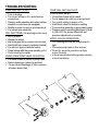
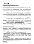
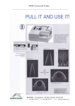
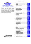
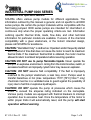
freshwatersystems.com serving you since 1989 INDUSTRIAL PUMP 8000 SERIES ® Installation and Operation Manual SHURflo offers various pump models for different applications. The information outlined by this manual is general, and not specific to all 8000 series pumps. Be certain the pumps' materials will be compatible with the fluid being pumped. 8000 series pumps are intended for intermittent or continuous duty when the proper operating criteria are met. Information outlining specific thermal limits, loads, flow data, and other technical information for particular models are available. If unsure of the chemical compatibility with a given elastomers, or the motors’ intended design, please call SHURflo for assistance. CAUTION: "Intermittent Duty" is defined as: Operated and/or frequently started within a period of time that does not cause the motor to reach its maximum thermal limits. If the maximum thermal limit is obtained, the motor must be allowed to return to ambient temperature before resuming operation. CAUTION: DO NOT use to pump flammable liquids. Never operate the pump in an explosive environment.. Arcing from the motor brushes, switch, or excessive heat from an improperly cycled motor may cause an explosion. CAUTION: DO NOT assume fluid compatibility. If the fluid is improperly matched to the pumps' elastomers, a leak may occur. Pumps used to transfer hazardous or hot (max. temperature 170°F [76°C] Viton™ only) chemicals must be in a ventilated area to guard against the possibility of injury due to harmful or explosive liquid/vapors. CAUTION: DO NOT operate the pump at pressures which cause the motor to exceed the amperes rating indicated on the nameplate. Various pump models are equipped with thermal breakers to interrupt operation due to excessive heat. Once the temperature of the motor is within proper limits it will automatically reset, and the pump will start operation without warning. 911-314 Rev. R 5/08 Page: 1 of 8 CAUTION: To prevent electrical shock, disconnect power before initiating any work. In the case of pump failure, the motor housing and/or the fluid being pumped may carry high voltage to components normally considered safe. PRESSURE SWITCH OPERATION (If Equipped) The pressure switch reacts to outlet pressure, and interrupts power at a preset shut-off pressure, indicated on the pump label. When outlet pressure drops below a predetermined limit (typically 15-20 PSI. [1-1.4 bar] less than the shut-off pressure), the switch will close and the pump will operate until the shut-off (high) pressure is reached again. The shut-off pressure is factory-set to calibrated standards. CAUTION: Improper adjustment of the pressure switch setting may cause severe overload, or premature failure. Refer to SHURflo Service Bulletin #1031 for the proper adjustment procedure. Failures due to improper adjustment of the pressure switch setting will not be covered under the limited warranty. If the plumbing is restrictive, or the flow rate is very low, the pump may repressurize the outlet faster than the fluid is being released, causing rapid cycling (ON/OFF within 2 sec.). If the pump is subjected to rapid cycling during normal operation, or for infrequent periods, damage may occur. Applications that exhibit rapid cycling should have restrictions in the outlet minimized. If not feasible, consider a SHURflo Accumulator or a SHURflo "bypass" model pump. BYPASS OPERATION (If Equipped*) A bypass pump may be used in an application that would normally induce frequent starts/stops of the motor, and thereby create a potential for overheating. Models equipped with an internal bypass are designed to pump at high pressure while at low flow rates. Bypass models equipped with a switch may operate for several seconds even though the discharge side has been closed off. Models equipped with a bypass only will continue to run until the power is turned OFF. MOUNTING • The 8000 series pumps are self-priming. Horizontal and vertical prime vary depending on the fluid viscosity and pump configuration. Refer to the pumps’ Flow vs. Pressure Data. • The pump should be located in an area that is dry, and provides adequate ventilation. If mounted within an enclosure, provisions to cool the motor may be necessary. Heat sinks, which attach to the motor, are available from SHURflo if increased heat dissipation is necessary. CAUTION: DO NOT locate the motor near low temperature plastics or combustible materials. The surface temperature of the motor may exceed 250°F [121°C]. • The pump may be mounted in any position. However, if mounting the pump vertically, the pump head should be in the down position, so that in the unlikely event of a leak, fluid will not enter the motor. • Secure the rubber feet with #8 hardware. DO NOT compress the feet; doing so will reduce their ability to isolate vibration/noise. PLUMBING • Use flexible, high-pressure tubing, compatible with the fluid to connect the inlet/outlet ports. Tubing should be either 3/8" or 1/2" [10 or 13 mm] I.D., and at least 18 in. [46 cm] length is suggested to minimize stress on the fitting/ports, and reduce noise. Allow for the shortest possible tubing route and avoid sharp bends that may kink over time. • Installation of a 50-mesh strainer is recommended to prevent foreign debris from entering the system. Failures due to foreign debris are not covered under the limited warranty. NOTE: Restrictions on the inlet may cause vacuum levels to reach the fluid vapor pressure, causing cavitation, degassing, vapor lock and a loss in performance. Inlet pressure must not exceed 30 psi [2.1 bar] maximum. • If a check valve is installed in the plumbing, it must have a cracking pressure of no more than 2 psi [.14 bar]. NOTE: SHURflo does not recommend the use of metal fittings, or rigid pipe, to plumb the inlet/outlet ports. Standard plastic male and female threaded fittings can be acquired at commercial plumbing supply stores. SHURflo also distributes Swivel Barb Fittings, and special fittings, through our dealers (See SHURflo website for list of available dealers). • 3/8" Female NPT models: In some cases, the ports may require a suitable thread sealer applied sparingly. DO NOT over-tighten, max. torque 3.7 ft\Lb (45 in\Lb) [5 Nm]. • 1/2" Male threaded models: Are intended to be used with SHURflo Swivel Barb Fittings, which seal with an internal taper when hand tightened. Standard 1/2" NPT fittings may be used when tightened to a max. torque of 3.7 ft\Lb (45 in\Lb) [5 Nm]. CAUTION: Sealers and Teflon tape may act as a lubricant, causing cracked housings or stripped threads due to over tightening. Care should be used when applying sealers. Sealers may enter the pump, inhibiting valve action, causing no prime, or no shut-off. A failure due to foreign debris is not covered under warranty. • Snap-Lock models: The slide fittings are open when the slide is moved out toward the switch. Fittings should be inserted flush against housing port before the slide is moved to the locked position. Fittings of Nylon or Polypropylene are available in various sizes. ELECTRICAL CAUTION: Electrical wiring should be performed by a qualified electrician, in accordance with all local electrical codes. • Improper duty cycle and/or rapid start/stop conditions may cause the internal thermal breaker (if equipped) to trip, or can result in premature motor failure due to excessive heat. Refer to the pumps’ Flow vs. Pressure Data. • Pumps should be on a dedicated (individual) circuit, controlled with a double pole switch (UL/C-UL certified) rated at, or above, the fuse ampere indicated by the pump motor label. Depending on the distance of the power source from the pump, and ampere load on the circuit, wires may need to be heavier than indicated by the chart. CAUTION: All 115 VAC and 230 VAC pump motors and systems, be grounded per local and state electrical codes. MUST • For the pump to meet UL/C-UL requirements the circuit MUST be protected with a slow-blow fuse (UL/C-UL certified), or equivalent circuit breaker, as indicated on the motor label. Use an approved wire of the size specified or heavier. VOLTAGE 12 DC 24 DC 36 DC 115 AC 230 AC MODEL 80XX-XXX-XXX 80XX-XXX-XXX 80XX-XXX-XXX 800X-X1X-XXX 800X-X2X-XXX 800X-X3X-XXX 800X-X6X-XXX 800X-X0X-XXX 809X-X0X-XXX 800X-X9X-XXX 809X-X1X-XXX FUSE (amp) 7.5 ~ 15.0 2.5 ~ 10.0 1.5 ~ 5.0 1.25 1.0 0.8 0.5 WIRE LEADS WIRE SIZE RED (positive +) BLACK (negative -) #14 AWG [2.5 Mm2] (or heavier) BLACK (common/hot) WHITE (neutral) GREEN (ground) BROWN (common/hot) BLUE (neutral) GRN/YELL (ground) #18 AWG C-UL / TEW 1015 (or heavier) [1 Mm2 ] CAUTION: Circuit protection is dependent on the individual application requirements. Failure to provide proper overload/thermal devices may result in a motor failure, which is not covered under the limited warranty. *The information outlined by this manual is general, and not specific to all 8000 series pumps. Contact the factory for information outlining technical specifications for a particular model. TROUBLESHOOTING PUMP WILL NOT START: 9 Fuse or breaker 9 For correct voltage (±10%) and electrical connections 9 Pressure switch operation and correct voltage at switch or motor wires (as equipped) 9 Rectifier or motor for open or grounded circuit 9 For locked drive assembly WILL NOT PRIME: (No discharge/motor runs) 9 Out of product 9 Strainer for debris 9 Inlet tubing/plumbing; severe vacuum leak 9 Inlet/Outlet tube severely restricted (kinked) 9 For debris in pump inlet/outlet valves 9 Proper voltage with the pump operating (±10%) 9 Pump housing for cracks LEAKS FROM PUMP HEAD OR SWITCH: 9 For loose screws at switch or pump head. 9 Switch diaphragm ruptured or pinched 9 For punctured diaphragm if fluid is present at bottom drain holes PUMP WILL NOT SHUT-OFF: (Pressure switch equip.) 9 Output line closed and no leaks 9 For air trapped in outlet line or pump head 9 For correct voltage to pump (±10%) 9 Inlet/Outlet valves for debris or swelling 9 For loose drive assembly or pump head screws 9 Pressure switch operation/adjustment (Refer to S/B #1031 for proper differential and pressure adjustment procedure) NOISY / ROUGH OPERATION: 9 For mounting feet that are compressed to tight 9 For loose pump head or drive screws 9 Does the mounting surface multiply noise (flexible) 9 Is the pump plumbed with rigid pipe causing noise transmission SERVICE KITS Kits are readily available to repair standard 8000 series pumps. Repair kits include simple illustrated instructions, allowing easy installation. To insure that the correct kit is received, the model number and all nameplate data must be included with the order. Contact a SHURflo distributor, or SHURflo directly, to order the necessary repair kit. KEY# 1 2 3 4 5 6 7 8 9 10 DESCRIPTION Complete assembled pump head Pressure switch assembly Check valve components Upper housing Valve assembly Diaphragm assembly Drive Assembly Motor Bypass Valve assembly Solid Diaphragm assembly 1 10 8 BYPASS MODELS W/O PRESS. SW. 7 4 6 3 2 5 BYPASS MODELS 9 INDUSTRIAL PRODUCT LIMITED WARRANTY SHURflo Industrial series pumps and products are warranted to be free of defects in material and workmanship under normal use, for a period of one (1) year from the date of manufacture, or one (1) year from date of purchase, with proof of purchase. This limited warranty will not exceed two (2) years, in any event. The limited warranty will not apply to pumps/products that were improperly installed, misapplied, damaged, altered, incompatible with fluids or components not manufactured by SHURflo. All Industrial pumps/products must be flushed of any chemicals before shipping. All warranty considerations are governed by SHURflo's written Return Policy. Returns are to be shipped postage prepaid to either service center; SHURflo Cypress, CA or Elkhart, IN. SHURflo shall not be liable for freight damage incurred during shipping. Package returns carefully. SHURflo's obligation under this warranty policy is limited to the repair or replacement of the pump/ product. All returns will be tested per SHURflo factory criteria. Products found not defective (under the terms of this limited warranty) are subject to charges paid by the returnee for the testing and packaging of "tested good" non-warranty returns. No credit or labor allowances will be given for pumps or products returned as defective. Warranty replacements will be shipped on a freight allowed basis. SHURflo reserves the right to choose the method of transportation. This limited warranty is in lieu of all other warranties, expressed or implied, and no other person is authorized to give any other warranty or assume obligation or liability on SHURflo's behalf. SHURflo shall not be liable for any labor, damage or other expense, nor shall SHURflo be liable for any indirect, incidental or consequential damages of any kind incurred by the reason of the use or sale of any defective product or part. This limited warranty covers industrial products distributed within the United States of America. Other world market areas should consult with the actual distributor for any deviation from this document. RETURN POLICY All Industrial pumps/products must be flushed of any chemical (ref. OSHA Section 1910.1200 (d)(e)(f)(g)(h)) and hazardous chemicals must be labeled / tagged before being shipped to SHURflo for service or warranty consideration. SHURflo reserves the right to request a Material Safety Data Sheet from the returnee for any pump/product it deems necessary. SHURflo reserves the right to "disposition as scrap" pumps/products returned which contain unknown fluids. SHURflo reserves the right to charge the returnee for any and all costs incurred for chemical testing, and proper disposal of components containing unknown fluids. SHURflo request this in order to protect the environment and personnel from the hazards of handling unknown fluids. Carriers, including U.S.P.S., airlines, UPS, ground freight, etc., require specific identification of any hazardous materials to be shipped. Failure to do so may result in a substantial fine and/or prison term. Check with your shipping company for specific instructions. ISO Certified Facility SHURflo reserves the right to update specifications, prices, or make substitutions. SHURflo 5900 Katella Ave. Cypress, CA 90630 (800) 854-3218 (562) 795-5200 FAX (562) 795-7564 Shipping: 5900 Katella Ave., Suite B Cypress, CA 90630 911-314 Rev. R 5/08 SHURflo East 52748 Park Six Court Elkhart, IN 46514-5427 (800) 854-3218 (574) 262-0478 FAX (574) 264-2169 © 2008 Printed in USA SHURflo Ltd. Unit 5 Sterling Park Gatwick Road, Crawley West Sussex, RH10 9QT United Kingdom +44 1293 424000 FAX +44 1293 421880 Page: 8 of 8