1
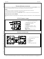
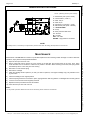
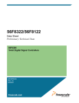
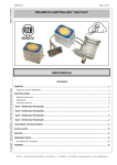
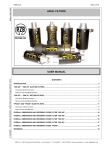
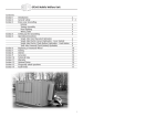
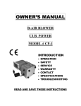
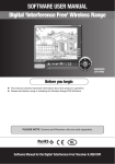
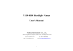
Edition 28/07/2002 PZB S.p.A. Pag.1 of 6 GF 100 FILTERING AND TEST UNIT Copyright – Reproduction prohibited. Listed data can be changed without notice. USER MANUAL CONTENTS GENERAL INFORMATION ............................................................................................................2 Filtration group ...................................................................................................................................... 2 Max. working pressure setting group ..................................................................................................... 2 “KIT ETA-PUMP” for testing the efficiency of the pump (optional) .......................................................... 2 WORKING OPERATIONS..............................................................................................................2 CIRCUIT CLEANING OR FILTERING .................................................................................................................. 2 CHECKING THE MAX. WORKING PRESSURE ..................................................................................................... 2 TESTING THE EFFICIENCY OF THE PUMP......................................................................................................... 3 Maximum working pressure (PROBE) ................................................................................................... 3 “GF-100” HYDRAULIC SCHEME..................................................................................................................... 3 WORKING FILTRATION SCHEME ..................................................................................................................... 3 WORKING EFFICIENCY TEST SCHEME ............................................................................................................. 4 MAINTENANCE..............................................................................................................................4 DIMENSIONS AND ORDERING CODES “GF-100”.......................................................................5 NOTES ...........................................................................................................................................6 Picture 1 (GF-100 hydraulic scheme) ........................................................................................................... 3 Picture 2 (Working hydraulic scheme) .......................................................................................................... 3 Picture 3 (Working efficiency test scheme) ................................................................................................... 4 Picture 4 (Overall dimensions GF-100) ......................................................................................................... 5 Table 1 (GF-100 technical specifications) ..................................................................................................... 5 Table 2 (GF-100 spare parts) ....................................................................................................................... 5 PZB S.p.A. - 40012 Calderara di Reno (BO) Italy – Via Persicetana, 2 – Tel. 0516460511 – Fax 051728528 – http://www.pzbitaly.com - E-mail: [email protected] PZB S.p.A. GENERAL INFORMATION Edition 28/07/2002 Pag.2 of 6 “GF-100” filtering unit is specifically designed to make hydraulic circuit cleaning easier before starting working operations or after a maintenance service. This operation is the key factor in order to supply to the client a correctcly working hydraulic system, without particles or foreign bodies that might jeopardize the operation of hydraulic and mechanical members. The new modern design allows the operator to easily control the circuit working parameters such as: - Hydraulic oil temperature coming out from oil tank - Pressure in the cleaning filter - Hydraulic circuit oil flow - Hydraulic circuit max. working pressure Moreover, the supporting trolley, provided with a shelf for tools, allows an easy handling and moving of the whole unit in the working area. FILTRATION GROUP The filtering unti is provided with a pair of filters in dual configuration. The first one has a filtering degree of 120 µm and the second one 60 µm. Bothe filters are interchangeable cartridge type retaining the possibility to increase the filtration degree until 25 µm using different cartridges. MAX. WORKING PRESSURE SETTING GROUP The “GF-100” unit is equipped with a manometer reading up to 600 bar, which can be connected to the max. pressure area of te hydraulic circuit, in order to check the real load levels and eventually adjust the max. pressure valve setting. “KIT ETA-PUMP” FOR TESTING THE EFFICIENCY OF THE PUMP (OPTIONAL) WORKING OPERATIONS The “GF 100” unit has been designed to perform the following operations CIRCUIT CLEANING OR FILTERING To correctly perform this operation, check the following procedure: 1) Disconnect exhaust pipe from oil tank 2) Connect the exhaust pipe to the inlet (IN) located on the left side of the filtering unit 3) Connect a new pipe from the outlet port (OUT) of the filtering unit to the exhaust port of the tank. In case a filter is fitted to the tank, remove the filtering cartridge from it to allow a free flowing to the tank of the oil filtered by the filtering unit GF 100. In any case, the maximum exhaust pressure (after the GF 100) must be lower than 5 bar. 4) Start up the whole installation in order to reach a complete rotation of the oil contained in the tank. The duration of the required cycle (in minutes) can be easily calculated dividing the tank capacity (in litres) by the pump displacement (ltres per minute). CHECKING THE MAX. WORKING PRESSURE Connecting with the supplied pipe M16 the max. pressure circuit area to the inlet port of the high pressure manometer located on the the left side of the filtering unit, the real working pressure of the hydraulic system can be checked. Thanks to the value indicated by the GF 100 filtering unit, you can set the maximum pressure relief valve of the circuit at the required value. NOTE: Before effecting this operation, it is necessary to contact with the manufacturer or distributor of the hydraulic components of the system to check the maximum value which the valve must open at. PZB S.p.A. - 40012 Calderara di Reno (BO) Italy – Via Persicetana, 2 – Tel. 0516460511 – Fax 051728528 – http://www.pzbitaly.com - E-mail: [email protected] Copyright – Reproduction prohibited. Listed data can be changed without notice. With the “KIT ETA-PUMP” aviable on request, the “GF-100” unit can testing the efficiency of the pump (pressure – flow). Edition 28/07/2002 PZB S.p.A. Pag.3 of 6 TESTING THE EFFICIENCY OF THE PUMP Connecting with the supplied pipe M16 the max. pressure circuit area to the inlet port of the “KIT ETA-PUMP” as show in the Picture 3 (Working efficiency test scheme), the real efficiency of the pump can be checked. NOTE: For safety reason, is necessary to verify the Max. pressure relief valve setting (300 bar) before to start the test. The best conditions of the test are: Oil ISO WG46 – Temperature 35-45°C. The maximum pressure for the pipe going to the “KIT ETA-PUMP” is 300 bar. For safety reason, never exceed this pressure limit. MAXIMUM WORKING PRESSURE (PROBE) The maximum pressure for the pipe going to the manometer is 400 bar. For safety reason, never exceed this pressure limit. “GF-100” HYDRAULIC SCHEME Picture 1 (GF-100 hydraulic scheme) Copyright – Reproduction prohibited. Listed data can be changed without notice. 1 – Manometer (max. press. 10 bar ) 2 – Thermometer ( 0-100°C ) 3 – Filter 120 µm 4 – Filter 60 µm 5 – Flowmeter ( 0-100 l/min – 5 bar ) 6 – Manometer (max.press. 600 bar) IN – Oil inlet OUT – Oil outlet PROBE – High pressure connection WORKING FILTRATION SCHEME Picture 2 (Working hydraulic scheme) 1 – GF-100 Filtering unit 2 – Oil tank 3 – Hydraulic circuit 4 – Suction filter 5 – Pump 6 – Max. pressure relief valve PZB S.p.A. - 40012 Calderara di Reno (BO) Italy – Via Persicetana, 2 – Tel. 0516460511 – Fax 051728528 – http://www.pzbitaly.com - E-mail: [email protected] PZB S.p.A. WORKING EFFICIENCY TEST SCHEME Picture 3 (Working efficiency test scheme) Edition 28/07/2002 Pag.4 of 6 1 – Manometer (max. press. 10 bar ) 2 – Thermometer ( 0-100°C ) 3 – Filter 120 µm 4 – Filter 60 µm 5 – Flowmeter ( 0-100 l/min – 5 bar ) 6 – Manometer (max.press. 600 bar) 7 – “KIT ETA-PUMP” 8 – Pump 9 – Max. pressure relief valve 10 – Oil tank IN – Oil inlet OUT – Oil outlet PROBE – High pressure connection NOTE For safety reason, is necessary to verify the Max. pressure relief valve “9” setting (300 bar) before to start the test. MAINTENANCE 1) Open the front port of the GF 100 2) With a hexagonal wrench remove the cover screws of the first filter (the located closer to the port). Then, place under the filter cover a container to collect the oil present in the filter. When removing the screws, the spring inside the filterwill push the cover away from the housing 3) Remove the cover and the spring 4) Remove the cartridge 5) Clean the cartridge and/or replace it (in case you have to replace it, use origianl cartridge only). Pay attention to the by pass valve 6) Insert the cartridge in the original position 7) Insert the spring and fit the cover back in place, paying attention that the gasket is not damaged and correctly placed 8) Lock the cover with the screws originally removed 9) Repeat the same procedure with the second filter 10) Close the front port of the GF 100 unit Note: For any further operation different from the above described, please contact the manufacturer PZB S.p.A. - 40012 Calderara di Reno (BO) Italy – Via Persicetana, 2 – Tel. 0516460511 – Fax 051728528 – http://www.pzbitaly.com - E-mail: [email protected] Copyright – Reproduction prohibited. Listed data can be changed without notice. Maintenance of the GF 100 unit consists of a periodical replacement and cleaning of filter cartridge. In order to effect this operation, simply follow the steps listed herebelow: Edition 28/07/2002 PZB S.p.A. Pag.5 of 6 DIMENSIONS AND ORDERING CODES “GF-100” Picture 4 (Overall dimensions GF-100) Copyright – Reproduction prohibited. Listed data can be changed without notice. “GF 100” technical specifications Code Maximum pressure (bar) Maximum temperatur e (°C) Max. oil flow (l/min.) 10 100 100 Maximum pressure check circuit GF-100 400 - - Efficency Test circuit “GF-100” 300 Description Filtering circuit GF-100 0.00.99.008.00 0.99.00.349.00 100 Table 1 (GF-100 technical specifications) “GF 100” spare-parts Code Description Q.ty Notes 0.99.00.344.00 Cartridge filtering degree 120 µm 1 By-pass valve set at 1,5 bar 0.99.00.345.00 Cartridge filtering degree 60 µm 1 By-pass valve set at 1,5 bar 0.99.00.346.00 Cartridge filtering degree 25 µm 1 By-pass valve set at 1,5 bar 0.99.00.347.00 Cartridge filtering degree 10 µm 1 By-pass valve set at 1,5 bar 0.99.00.348.00 High pressure mini-connector 1 Lenght 3 mt. – Threaded connector M16 2.99.141.0000 KIT ETA-PUMP (3/4”) 1 Max 300 bar – 100 Lpm Table 2 (GF-100 spare parts) PZB S.p.A. - 40012 Calderara di Reno (BO) Italy – Via Persicetana, 2 – Tel. 0516460511 – Fax 051728528 – http://www.pzbitaly.com - E-mail: [email protected] PZB S.p.A. NOTES Edition 28/07/2002 Pag.6 of 6 Copyright – Reproduction prohibited. Listed data can be changed without notice. This Edition 28/07/2002 of the catalogue cancels and replaces any previous edition. Dimensions and techncial specifications of the items shown in this catalogue can undergo any modification at the discretion of our technical department and without previous information. The drawings included in this catalogue are protected by copyright. Always indicate complete codes in your order. General sales condition are mentioned in the valid list price. PZB S.p.A. - 40012 Calderara di Reno (BO) Italy – Via Persicetana, 2 – Tel. 0516460511 – Fax 051728528 – http://www.pzbitaly.com - E-mail: [email protected]