1
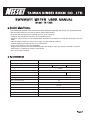
TAIWAN NISSEI SOKKI CO . , LTD .
SWR / WATT METER USER MANUAL
Model : TX-1202
Product Main Feature
This wattmeter series offer many innovative features typically not found at this price level
• DC Grounded Antenna connector prevents electrostatic buildup.
• True Directional Coupler for increased accuracy over frequency.
• Low Bias Schottky Diode Detectors for increased linearity.
• Precision, large (104mm) Cross Needle Meter simultaneously displays forward and reflected power with
SWR.
• Individual Meter Scales for each power range increase reading accuracy.
• LED backlighting provides smooth, even illumination.
• Three Color Scale for improved readability.
• Rugged metal cabinet with speckled black finish and designer style grey injection molded front panel
aesthetically complements modern transceivers.
• DC Power Cable Included.
Specifications
TX-1202
MODEL
1.6MHz-1300 MHz
Frequency Range
Center Calibrated
435 MHz
28.5/145 MHz
0 - 200W
Power Range
2/20/200W
Power Scale
Maximum Power
200W
Accuracy
± 10% of Full Scale or better
Insertion Loss
Min. Power (Forward)
Testing Function
1260 MHz
20W
Less than 0.1dB
1W
Forward Power, Reversed Power, SWR, PEP
Input/Output Impedance
50 ohm
Input/Output Connectors
“M” type for HF/VHF Band,“N” type for UHF Band
Input power
Dimension (W/H/D)
Weight (Net)
9-14 VDC 200 mA (Max.)
184 X 118 X 131 m/m
1100g
Page1
Front Panel
<DESCRIPTION>
1
2
AVG
HF
VHF
UHF
70cm
UHF
25cm
3
PEP
LED OFF
10
100
4
1. Indicator Display : Indicates FWD/REV power in watts and VSWR ratio
2. AVG/PEP (elliptical) push botton : Select AVG (out) or PEP (depressed)
3. Frequency switch : Select frequency measured
4. Range switch : Selects RF power range multiplier x1 x10 x100
5.LED ON/OFF button (elliptical) : Turn LED lamp
6. Zero adjust screws of analog cross needle meter
ON
6
Rear Panel
5
<DESCRIPTION>
7
9
8
7. TX connector : Coax connector to transmitter 50 ohm RF output
8. ANT connector : Coax connector to 50 ohm antenna system
9.13.8V DC connection (via power supply) : LED illumination
Note 1 : Watch out the LED wire must be correctly connected, black/
white to '+', Black to '-'. Wrong connection burn LED)
Note 2 : DC power is only required to run the meter backlight. This
meter will function w/o DC power in the AVG mode, even when
switch off.
Forward /Reverse Pwr /SWR Measurement
A. Set the RANGE switch to the proper meter multiplier (X1, X10, X100) for the
expected power level of the intended measurement.
B. In TX-1202, it corrosponds to 2/20/200 watts forward and 0.5/5/50 watts
reflected full scale (Fwd : Ref = 4 : 1)
C. Select the frequency needed (HF/VHF/UHF amateur bands)
D. Set the radio transceiver to transmit mode and read the scale corresponding
to the RANGE selected
E. When switch to 'AVG', the meter reads average RF power.When switch to
'PEP', the meter reads Peak Envelope Power for use withSSB and AM
transmissions. In this mode, there will be a slow rise and decay time.
F. Push LED ON/OFF button when LED light is needed
<INSTALLATION>
12V DC
Caution
1. Since the meter movement is very sensitive, avoid excessive vibration or mechanical shock to the meter.
2. Watch the absolute maximum power could be applied to the meter by different models you bought.
3. The meter must never be reverse connected. Always observe the correct connections to transmitter and
antenna as indicated on the rear sockets.
4. Do not expose the meter to excessive temperatures, high humidity, or strong magnetic fields.
5. Contact your local dealer for service. Dealer information is in the back of user manual.
RoHS
Page2