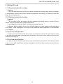
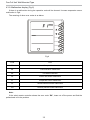
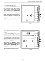
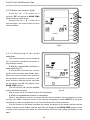
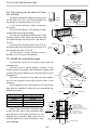
1
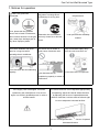
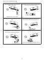
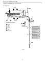
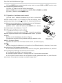
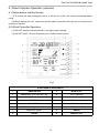
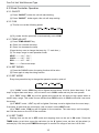
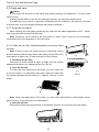
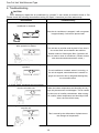
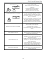
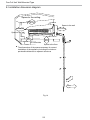
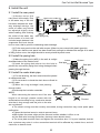
USER MANUAL
WALL MOUNTED FAN COILS
SF-51H, SF-68H, SF-85H
User Notice
This symbol stands for items should be forbidden.
This symbol stands for
the items should be followed.
Thank you for choosing SINCLAIR fan coils, please read this owner's manual
carefully before operation and keep it for fucture reference.
The products in this manual may be different from the real one, according to different
models, some models have displayer and some models without displayer, the position
and shape of the displayer please refer to the real one.
This appliance is not intended for use by persons (including children) with restricted
physical, sensory or mental capabilities or lack of experience and knowledge, unless they
have been given supervision or instruction concerning use of the appliance by a person
responsible for their safety.
Children should be supervised to ensure that they do not play with the appliance.
Do not dispose this product as unsorted municipal waste. Collection of such
waste separately for special treatments necessary.
Contents
1. Notices for operation.........................................................................1
2. Notices for use..................................................................................3
3.Name and function of each part........................................................4
4. Wired Controller Operation (optional)................................................9
5. Emergency operation......................................................................15
6. Troubleshooting...............................................................................18
7. Notices for installation.....................................................................20
8. Installation dimension diagram........................................................22
9. Install the unit..................................................................................23
10. Install the connection pipe.............................................................24
11. External water pipe connection sketch..........................................25
12. Check after installation and test operation....................................26
Fan Coil Unit Wall Mounted Type
1. Notices for operation
Earth: The ground be
connected!
Be sure to pull out the power
plug when not using the air
codictionary for a long time.
Select the most appropriate
Otherwise, the accumulated
It can preclude the electricity
tempremature.
If not, please ask the qualified
person-nel to install. Furthermore,
don't connect each wire to the gas
pipe, water pipe, drainage pipe or
any other improper places.
dust may cause fire or electric
wasted.
shock.
Don't leave windows and doors
Don't block the air intake or
Keep combustible spray away
open for a long time while
outlet vents of both the units.
from the units more than 1m.
operating the air conditioner.
It can decrease the airconditioning
capacity.
It can cause a fire or explosion.
It can decrease the air
conditioning capacity or cause a
malfunction.
If the supply cord is damaged, it must be
The airflow direction can be adjusted appropriately.
replaced by the manufacturer or its service
At operating, adjust the vertical airflow direction
agent or a similarly qualified person in order to
by adjusting the louvers of upward/downward
avoid a hazard.
direction. And then, hold two ends of left and right
louver to adjust the horizontal air-flow.
Louver of left/right direction
Louver of upward/
downward direction
1
Fan Coil Unit Wall Mounted Type
Don't insert your hands or stick into the air
Don't blow the wind to animals and plants directly.
intake or outlet vents.
It can cause a bad influence to them.
Otherwise it will cause accident.
Don't apply the cold wind to the body for a long
Don't use the air conditioner for other purposes,
time.
such as drying clothes, preserving foods, etc.
Splashing water on the air conditioner can
Don't place a space heater near the air conditioner.
cause an electric shock and malfunction.
Or CO toxicsis may occur for incomplete burning.
2
Fan Coil Unit Wall Mounted Type
2. Notices for use
2.1 Working principle for cooling
Principle:
●● The unit absorbs energy from the air indoors and takes the energy away through circulation
of cooling water, so as to reduce indoor ambient temperature. Accordingly, the cooler the water, the
larger the cooling capacity.
2.2 Working principle for heating
Principle:
●● Air circulation, which is forced by the fan, transfers the energy from hot. water to the air
indoors so as to increase indoor ambient temperature.
●● Accordingly, the hotter the water, the larger the heating capacity.
●● Because heating capacity of such air circulation system is closely related to the temperature
of hot water, if water temperature is not high enough, additional heating appliance is recommended
to use together.
2.3 Anti-cool-wind function
In order to ensure comfort of the users, under circumstances such as the heat mode just starts
or the unit runs heat mode under low water temperature, the fan will stop running to prevent the
chilled wind blowing out.
2.4 Anti-heat-wind function
In order to ensure comfort of the users, under circumstances such as the cool mode just starts
or the unit runs cool mode under hot water temperature, the fan will stop running to prevent the hot
wind blowing out.
3
Fan Coil Unit Wall Mounted Type
3.Name and function of each part
3.1 The unit
Air in
Air out
The patten in displayer:
Cool
Dry
Fan
Heat
Run
Set temp.
Wireless
remote control
(1) Power cable
(2) Remote control
(3) Front panel
(4) Filter
(5) Guide louver
(6) Wall pipe
(7) Bind tape
(8) Drain pipe
Fig.1
4
Fan Coil Unit Wall Mounted Type
3.2 Operation of wireless remote control
Note: Be sure that there are no obstructions between receiver and remote control; Donot drop
or throw the remote control; Don't let any liquid drop into the remote control or leave the remote
control under the sunlight or place where is very hot.
●● ON/OFF
Press ON/OFF button to turn on/off the unit. When the unit is turned off, the Timer, Sleep
function will not be retained in memory, but the time will be retained and is still displaying.
●● MODE
MODE button
(1) Press this button, Auto, Cool, Dry, Fan Heat mode can be selected circularly.
(2) Under Cool mode, the initial value is 24°C(75°F) . Under Heat mode, the initial values
24°C(75°F).
(3) Auto mode is not available in this mode.
AUTO
COOL
DRY
FAN
HEAT
●● SLEEP
SLEEP button
Press this button to select Sleep On/Sleep Off. If power is on, Sleep
Off is default. If the unit is turned off, the Sleep function setting will be
not retained in memory. If Sleep function is on, the mark of Sleep will
display. In this mode, the time of timer can be adjusted. Under Fan and
Auto modes, this function is not available.
●● FAN
FAN button
Press this button, Auto, Low, Medium, High-speed can be circularly
selected. After powered on, Auto fan speed is default. Under Dehumidify
mode, Low fan speed is default.
AUTO
Low
Medium
High
Note: Under the Dry mode, the fan speed isn't adjustable, low fan speed is default.
●● CLOCK
CLOCK button
Press Clock button to set the time of clock. When
blinks and displays, you can set
the time by pressing + or - button. If no button is pressed within 10 seconds the remote
will revert back to the normal display. Press
again to accept the setting. If it is set the
first time, 12:00 is the initial value. Note: If mark
displays on the LCD, it means it is the
time of clock, if not, it is the time of timer.
5
Fan Coil Unit Wall Mounted Type
●● LIGHT
LIGHT button
Press this button to select LIGHT On/Off in the displayer. When the LIGHT On is LIGHT
buttonLIGHTset,the mark
will be displayed and the indicator light in the displayer will be on. When
the LIGHT Off is set, the mark
will disappear and the indicator light will be off.
3.3 Operation of wireless remote control
Note: This is a general remote control, it could be used for
multiple types (functions) of air conditioners. For some models without
the functions specified here, we preserve the right to not to inform
exclusively.
●● X-FAN
X-FAN button
(1) Press this button to turn on/off the X-FAN function.
(2) The function is not available for this mode.
●● - button
Presetting temperature can be decrease the temperature by 1
degree Celsius once. press and hold for more than two seconds so
that we can change the temperature continuously. The minimum and
maximum setting range of the temperature is 16 to 30 degree Celsius.
●● + button
Press this button increase the temperature by 1 degree Celsius
once. Press and hold for more than two seconds so that we can
change the temperature continuously. The minimum and maximum
setting range of the temperature is 16 to 30 degree.
●● TEMP
TEMP button
Press this button to select the display of either indoor setting temperature or indoor ambient
temperature. When the indoor unit powered on firstly, setting temperature display is default. Change
status to to display the ambient temperature. If received control signal in 5 seconds, the display
temp.will revert back to setting temperature. When unit is off, indoor setting temperature display is
default. Note: This function is only available for certain models.
●● TURBO
TURBO button
In Cool or Heat mode, press this button to turn on/off the Turbo function.
Note: This function is not available for this model.
6
Fan Coil Unit Wall Mounted Type
3.4 Operation of wireless remote control
Note: This is a general remote control, it could be used for multiple types (functions) of air
conditioners. For some models without the functions specified here, we preserve the right to not to
inform exclusively.
●● SWING UP AND DOWN BUTTON
Press this button to adjust swing angle, which circularly changes as below:
OFF
This is a general use remote control. If remote control shows the
following three kinds of status that the swing status of main unit will
be:
When the guide louver start to swing up and down, if turn off the
Swing, the air guide louver will stop at current position.
which indicates the guide louver swings up and down between
the five positions.
●● TIMER ON BUTTON
Press the TIMER ON button to set the timed On. Press +/- once to
increase or decrease the minute by 1 minute. If pressed and held for 2
seconds, the minute will increase or decrease constantly by 1 minute.
If held constantly for more than 5 seconds, the minute will begin to
change in every 10 minutes. Press TIMER ON again to accept the
setting and ON will show besides the time of clock meaning the setting
succeeds. Press the TIMER ON again to cancel the setting.
●● TIMER OFF BUTTON
Press the TIMER OFF button to set the timed Off. The procedures are similar as above.
3.5 Operation of wireless remote control
3.5.1 Guide for operation – General operation
(1) Press SLEEP button to set the sleep state.
(2) Press TIME ON and TIME OFF button to scheduled the unit ON/
OFF
(3) Press LIGHT button to control on and off the indicator board.
(This function maybe not available for some units).
3.5.2 Guide for operation-Optional operation
(1) After powered on, press ON/OFF button, the unit will start to run.
(Note: When it is powered off , the guide louver of main unit will close
automatically.)
7
Fan Coil Unit Wall Mounted Type
(2) Press MODE button, select desired running mode ,or press COOL or HEAT mode to enter
the corresponding operation directly.
(3) Press + or-button to set the desired temperature.
(4) Press FAN button to set fan speed from AUTO, FAN ,LOW MID and HIGH.
(5) Press+_ button to select SWING mode.
3.5.3 Operation of wireless remote control
(1) Press +and - buttons simultaneously to lock or unlock the
wireless remote control. If it is locked, the mark will display; when
pressing any button, the mark
will blink for three times but the air
conditioner has no despondence. If unlocked, the mark will disappear.
(2) Switch between Fahrenheit and Centigrade.
(3) When unit is under Off state, press MODE and – button
simultaneously to switch between ℃ and ℉ .
Fig.1
3.6 Changing batteries and notices.
(1) Slightly to press the place with
, along the arrowhead
direction to push the back cover of wireless remote control. (As show
in figure)
(2) Take out the old batteries. (As show in figure)
(3) Insert two new AAA1.5V dry batteries, and pay attention to the
polarity. (As show in figure).
(4) Attach the back cover of wireless remote control. (As show in figure)
Fig.2
Sketch map for
changing batteries
NOTE:
●● When changing the batteries, do not use the old or different batteries, otherwise, it can cause
the malfunction of the wireless remote control.
●● If the wireless remote control will not be used for a long time, please take them out, and don't
let the leakage liquid damage the wireless remote control.
●● The operation should be in its receiving range.
●● It should be placed at where is 1m away from the TV set or stereo sound sets.
●● If the wireless remote control can not operate normally, please take them out, after 30s later
and reinsert, if they cannot normally run, please change them.
8
Fan Coil Unit Wall Mounted Type
4. Wired Controller Operation (optional)
4.1 Notice before starting the unit.
(1) To ensure the heat exchanging, the air in the fan coil of the unit must be exhausted before
using.
(2) Before starting the unit , make sure that the cable connection of the fan coil is correct and no
sundries in the duct.
4.2 Wired Controller Operation
(1) DO NOT install the wired controller in the place water leakage.
(2) DO NOT knock , throw or frequently turn on/off the wired controll
Fig.3
STRUCTURE OF EACH PARTS
1
TIMER ON/OFF
9
MODE button
2
FAN display (Auto,High,Mid,Low)
10
Temp. Adjust(up)
3
Energy Saving display
11
Temp. Adjust(down)
4
SET TEMP.
12
FAN button
5
ROOM TEMP.
13
SWING button
6
MODE (Coo, Dry, Heat and Fan)
14
TIME ON /OFF
7
Malfunction display
15
ON/OFF
8
SLEEP
16
SWING display
9
Fan Coil Unit Wall Mounted Type
4.3 Wired Controller Operation
4.3.1 ON/OFF
(1) Press “ON/OFF” button this unit will start working.
(2) Press “ON/OFF” button again, this unit will stop working.
4.3.2 FAN
(1) This fan runs at the following speed:
(2) Dry mode: the fan speed will be automatically set to LOW.
4.3.3 TEMP ADJUST
(1) Press TEMP ADJUST key
▲: Press it to increase the temp;
▼: Press it to decrease the temp.
(Press the key once to change the temp. by 1℃ each time.)
(2) The temp. range in each operation mode:
HEAT----------16℃ - 30℃ ;
COOL---------16℃ - 30℃ ;
DRY-----------16℃ - 30℃ ;
FAN-----------Can not set temp.
4.3.4 SET SWING
(1) Press the SWING button, the swing function will be ative.
(2) Press again to stop the swing function.
4.3.5 SET MODE
Every time press this key to change the operation mode in order of:
(1) In “COOL” mode, COOL key will be lighted and set temp. must be lower than temp. If set
temp. is higher than room temp. , this unit won’t run in COOL mode and only fan can operate.
(2) In “DRY” mode, DRY key will be lighted and internal fan will work at high speed within a
certain temp. range. This mode is more efficient than DRY function in COOL mode and it can save
the energy.
(3) In “HEAT” mode , HEAT key will be lighted. Set temp. must be higher than the room temp. ;
If set temp, is lower than the room temp., this unit won’t run the HEAT mode.
(4) In “FAN” mode , FAN key will be lighted. In the meantime. The room temp. can’t be adjust ,
but it will be shown on the LCD of the controller.
4.3.6 SET TIMER
Starting time can be set in OFF mode and stopping time can be set in ON mode. Press the
TIMER button to set timer, press the ▲ button (or the ▼ button) once, set time will be raised (or
reduced) by 0.5h, then press TIMER button again to confirmThe range of set time is 0.5h~24h.
10
Fan Coil Unit Wall Mounted Type
4.3.7 Energy Saving Setting (Fig.4).
(1) In the status of OFF, press the button
FAN and ▼ simultaneously for 5seconds,
MO DE
the SAVE menu will appear and comes to
the energy saving settings of cooling and dry
(showing SAVE + COOL, for the first time
of setting, the initial temperature is 26);then
press MODE button, it changes to energy
FAN
saving setting of heating mode (showing
SAVE + HEAT, for the time of setting, the
SW IN G
initial temperature is 20 ℃ ); The upper limit
COOL
TI ME R
temp. is set at the SET TEMP, the lower
temp. limit is set at the ROOM TEMP. ,
ON /O FF
press ON/OFF button to switch over the
upper/lower temp. limit setting, press ▲ and
▼ to adjust the temperature(the range is
Fiig.4
16~30 ℃ ). After finishing the setting ,press
FAN and ▼ simultaneously again for 5 seconds, and exit the SAVE menu.
(2) After the operation above ,SAVE will be display on the liquid crystal panel, then neither the
remote controller nor the wired controller the user use to set the temperature, the SET TEMP. will
not exceed the range that has been set. For example, in the Fig.2 we set temp. range from 23 ℃
to 28 ℃ ,then the user can only adjust the
temp. between 23℃ and 28℃ by the remote
controller or the wired controller.
(3) If the upper limit is the same with the
MO DE
lower limit that the system can only run at
this temperature.
(4) To cancel the energy saving, press
the button of FAN and ▼ simultaneously for
5 seconds in the status of OFF, but temp.
FAN
limit will be keep until next time to set the
energy saving function.
SW IN G
(5) After the power cut, the energy
saving function will still be store in memory.
TI ME R
NOTE: The upper limit can not be lower
than the lower limit, or else the system will
ON /O FF
default the higher one to be upper limit, if
there is no operation in 20 seconds, the
Fiig.5
SAVE menu will automatically shut down.
4.3.8 Memory function (Fig.5)
Press the MODE button for 10 seconds in the OFF status, the memory function can be switch
over., If“01”is showed,it means the memory function is on,or else if “02”is showed, it means the
memory function is off. Press ON/OFF button to exit. If there is no operation is 20 seconds, the
memory function menu will be shut of and the present setting will be stored.
11
Fan Coil Unit Wall Mounted Type
4.3.9 Malfunction display (Fig.6)
If there is a malfunction during the operation code will be showed. It means evaporator sensor
malfunction is Fig4.
The meaning of other error codes is as below:
MO DE
FA N
SW IN G
TI ME R
ON /O FF
Fig.6
Code
Error
E0
Pump malfunction
E6
Communication malfunction
E9
Full-water Protection
F0
Indoor unit sensor malfunction
F1
Evaporator sensor malfunction
F5
Wired controller sensor malfunction
EH
Auxiliary electric heater malfunction
Note:
If the wired remote controller shows the error code “EH”, lease cut off the power and find the
professional to fix the problem.
12
Fan Coil Unit Wall Mounted Type
4.3.10 Sensor setting (Fig.7)
Press the “FAN+SWING” button
for 10 seconds in the “OFF ”status to
enter the senor setting menu. A code
will be displayed on the “ROOM TEMP.”
“01”means the indoor unit sensor, and
“02”means the wired controller senor,
press “▲”and “▼”to chose the senor. If
there is no operation in 20 seconds, the
system will exit this menu and the present
setting will be saved, or else press “ ON/
OFF ” button to save and exit.
MO DE
FAN
DEBUG
SW IN G
TI ME R
ON /O FF
Fiig.7
4.3.11 System parameters display
(Fig.8)
MO DE
Press “FAN+SWING” for 10 seconds
while the system is ON to enter the
system parameters displa interface.
The temperature of the water valve,
pump and surface cooler in the system.
The temperature of the surface cooler
is display at “ TIMER ”the two position
value display at “ TEMP.SET ” means
“Valve 1” and “Valve 2”, the status of the
pump displays at “ ROOM TEMP. ”and “1”
means ON while “2” means OFF. Press
ON/OFF button to exit or else the system
will automatically exit after 30 minutes.
FAN
SW IN G
TI ME R
ON /O FF
Fiig.8
13
Fan Coil Unit Wall Mounted Type
4.3.12 Button lock function (Fig.9)
Press the “▲” + “▼” button for 5
seconds, “EE” will appear at ROOM TEMP
and the buttons will be locked.
Presses the “▲” +“ ▼ ” button for 5
seconds again, the button locked function
will be canceled.
MO DE
FAN
SW IN G
COOL
TI ME R
ON /O FF
Fiig.9
4.3.13 Monitoring of the wired
controllers
MO DE
The wired controllers can be monitored
by a connected centralized controller or
long-distance monitor.
●● While a centralized controller is
connected (Fig.10)
A centralized controller can monitor
all the wired controllers and disable them.
When the wired controllers are rocked by
the centralized controller, the button of the
COOL
wired controller and the remote controller
are all locked, and “CC” will appear at the
ROOM TEMP location.
The lock function can also be disabled
Fiig.10
by the centralized controller.
After a power cut off, the locked function will be disabled.
FAN
SW IN G
TI ME R
ON /O FF
●● While a long-distance monitor is connected
When a long-distance monitor connects with the wired controller, the long-distance monitor
not only can make a real-time control of the velocity\ temperature\ mode\ ON\OFF of the wired
controllers, but also can disable some or all of the functions of the wired controllers.
If all the functions of the wired controllers are locked, the buttons of the wired controller and the
remote controller are all disable, and the code “CC” will display at the ROOM TEMP location. If one
or some of the functions are locked, the other functions still work, and nothing will display on the
panel.
14
Fan Coil Unit Wall Mounted Type
When the functions are locked, the lock function can only be canceled by the long-distance
monitor or by pressing MODE+▼ for 5 seconds. The lock function can be kept in the memory after
the power-off.
4.3.14 Set the address code of the
wired controller (Fig.11)
MO DE
(1) An address code of long-distance
monitoring can be set to the wired
controller and the main-board.
(2) Press MODE+▲ for 5 seconds
in the OFF status to enter the addresswriting menu.(Fig.10), then the present
FAN
DEBUG
address code will flickeringly display at
SW IN G
the TIMER location (the default code is
0), and “DEBUG” will also flickeringly
TI ME R
display at the same time. Press▲ + ▼ to
choose the address code with the range
ON /O FF
of 1~2999. Press ON/OFF to confirm,
then if the address code stop flickering,
Fiig.11
it means the code of the wired controller
is successfully written; if “DEBUG” stop
flickering that means the code of the mainboard is successfully written.
(3) If there is no operation within 20 seconds, the menu will automatically exit, or else press the
button “MODE+▲” for 5 seconds to exit.
5. Emergency operation
5.1 Indicator light control of the displayer
When sleeping at night, the user can get the
indicator light off.
(1) Get the displayer indicator light on: When setting
the light function, the mark 8 will display on the remote
Manual switch
controller screen by pressing this button. In which case,
Fiig.12
the displayer indicator light will be on if the AC receives
this signal.
(2) Get the displayer indicator light off: If cancel the light function, the mark 8 will disappear on
the remote controller screen by pressing this button. In which case, the displayer indicator light will
be off if the AC receives this signal.
5.2 Emergency operation
If the wireless remote control is lost or broken, please use the manual switch button. The unit
will run at the mode which was setted before turned off, but the temperature and fan speed cannot
be changed.
Open the front panel, the manual switch is on the edge as Fig.12.
15
Fan Coil Unit Wall Mounted Type
5.3 Clean and care
Caution
● Turn power off and pull out the power plug before cleaning air conditioner, or it may cause
electric shock.
● Never sprinkle water on the unit for cleaning because it can cause an electric shock.
● Volatile liquid (e.g. thinner or gasoline) will damage the air conditioner. (So wipe the units with
a dry soft cloth, or a cloth slightly moistened with water or cleanser.)
5.3.1 Clean the front panel
When cleaning the front panel, please dip the cloth into the water temperature of 45℃ below,
then to dry the cloth and wipe the dirty part.
Note: Please do not to immerse the front panel in water, due to there are microcomputer
components and circuit diagrams on the front panel.
5.3.2 Clean the air filter (Recommended once every three
months)
Note: If dust is much more around the air conditioner, the air
filters should be cleaned many times. After taking off the filter, don't
touch the fin of indoor unit, in order to avoid hurt your fingers.
●● Take down the air filter
At the slot of surface panel to open an angle, pull the air filter
downward and take it out, please see the Fig.13(a, b).
●● Clean the air filter
To clean the dust adhering to the filters, you can either use
a vacuum cleaner, or wash them with warm water the water with
the neutral detergent should below 45 ℃ degree) ,and dry it in the
shade.
(a)
(b)
Fiig.13
Note: Never use water above 45 to clean, or it can cause deformation or discoloration. Never
parch it by fire, or can cause a fire or deformation.
●● Insert the air filter
Reinsert the filters along the direction of arrowhead, and then to cover the cover and clasp it.
16
Fan Coil Unit Wall Mounted Type
5.4 Clean and care
●● Check before use
1. Be sure that nothing obstructs the air outlet and intake vents.
2. Check that whether ground wire is properly connected or not.
3. Check that whether the batteries of air conditioner are changer or not.
●● Maintain after use
1. Turn main power off.
2. Clean the filter and the unit body.
17
Fan Coil Unit Wall Mounted Type
6. Troubleshooting
CAUTION
Don’t attempt to repair the air conditioner by yourself, it can cause an electric shock or fire.
Please check the following items before asking for repair, it can save your time and money.
Phenomenon
Not operate immediately when the air
Troubleshooting
conditioner is restarted.
Once the air conditioner is stopped, it will not operate
in approximately 3 minutes to protect itself.
There's unusual smell blowing from the outlet
after operation is started.
The unit has no peculiar smell by itself. If has, that is
due to the smell accumulated in the ambient.
Solution method: Cleaning the filter. If problem still
has, so need to clean air conditioner. (Please contact
with the authorized maintenance center.)
Sound of water flow can be heard during the
operation.
The air conditioner is started, when it is running, or
the unit is stopped, sometimes there is swoosh or
gurgle, the sound is due to refrigerant flowing they
are not malfunctions.
In COOL mode, sometimes the mist emitted
from the air outlet vent.
When the indoor temperature and humidity are very
high, this phenomenon would happen. This is caused
by the room air is swiftly cooled down. After running
for a while, indoor temperature and humidity will fall
down, the mist will die away.
Creaking noise can be heard when start or
stop the unit.
This is caused by the deformation of plastic due to
the changes of temperature.
18
Fan Coil Unit Wall Mounted Type
The unit can not run.
Is Temp. setting suitable?
Were inlet and outlet vents obstructed?
Is filter dirty?
Are the windows and doors clothed?
Did Fan speed set at low speed?
Is there any heat sources in the room?
Cooling(Heating) efficiency is not good.
The unit is interfered by abnormal or frequent
functions switchover occasionally the controller
cannot operate. At this time, you need to pull out of
the plug, and reinsert it.
Is it in its receiving range? Or obstructed? To check
the voltage in wireless remote control inside is
charged, otherwise to replace the batteries.
Whether the wireless remote control is damaged.
The air humidity is on the high side.
Wireless remote control is not available.
Condensing water over flowed.
The connection position of the unit drainage pipe is
loosed.
The sound of fan relay is switching on or off.
If water leakage in the room.
When the unit turn off. That is due to the water
flowed to the reverse direction.
In HEAT mode, when the temperature of the heat
exchanger is very low, that will stop deliver air in
order to prevent cool air.
In COOL mode, when the temperature of the heat
The unit cannot deliver air.
exchanger is very high, that will stop deliver air in
order to prevent hot air.
In dehumidifying mode, sometimes indoor fan
will stop, in order to avoid condensing water be
vaporized again, restrain temperature rising.
If unit is running under the high humidity for a long
Noise from the unit emitted.
time, the moisture will be condensed on the air
outlet grill and drip off.
19
Fan Coil Unit Wall Mounted Type
7. Notices for installation
7.1 Important Notices
1. The unit installation work must be done by qualified personnel according to the local rules and
this manual.
2. Before installing, please contact with local authorized maintenance center, if unit is
not installed by the authorized maintenance center, the malfunction may not solved, due to
discommodious contacts.
3. When removing the unit to the other place, please firstly contact with the authorized
Maintenance Center in the local area.
7.2 Basic Requirements For Installation Position
Installation in the following place may cause malfunction. If it is unavoidable, contact with
service center please.
(1) Place where strong heat sources, vapors, flammable gas or volatile object are emitted.
(2) Place where high-frequency waves are generated by radio equipment, welders and medical
equipment.
(3) Place where a lot of salinities such as coast exists.
(4) Place where the oil (machine oil) is contained in the air.
(5) Place where a sulfured gas such as the hot spring zones is generated.
(6) Other place with special circumstance.
7.3 The Unit Installation Position Selection
(1) The air inlet and outlet vent should be far from the obstruction, make sure that the air can be
blown through the whole room.
(2) Select a position where the condensing water can be easily drained out.
(3) Select a location where the children can not reach.
(4) Can select the place where is strong enough to withstand the full weight and vibration of the
unit. And will not increase the noise.
(5) Be sure to leave enough space to allow access for routine maintenance. The height of the
installed location should be 250cm or more from the floor.
(6) Select a place about 1m or more away from TV set or any other electric appliances.
(7) Select a place where the filter can be easily taken out.
(8) Make sure that the unit installation should accord with installation dimension diagram
requirements.
(9) Do not use the unit in the immediate surroundings of a laundry a bath a shower or a
swimming pool.
7.4 Safety Requirements For Electric Appliances
(1) The power supply be used the rated voltage and AC exclusive circuit, the power cable
diameter should be satisfied.
(2) Don’t drag the power cable emphatically.
(3) It should be reliably earthed, and it should be connected to the special earth device, the
installation work should be operated by the professional.
The air switch must have the functions of magnetic tripping and heat tripping, in order to protect
the short circuit and overloading.
20
Fan Coil Unit Wall Mounted Type
(4) The min. distance from the unit and combustive surface is 1.5m.
(5) The appliance shall be installed in accordance with notional wiring regulations.
(6) An all-pole disconnection switch having a contact separation of at least 3mm in all poles
should be connected in fixed wiring.
Note:
●● Make sure that the Live wire or Zero line as well as the earth wire in the family power socket
can not be wrong connected, there should be reliable and no short circuit in the diagram.
●● Wrong connection may cause fire.
7.5 Ground requirements
(1) Air conditioner is type I electric appliance, thus please do conduct reliable grounding
measure.
(2) The yellow-green two-color wire in air conditioner is ground wire and cannot be used for
other purpose. Cut off and fixed by screw as grounded is not permissible, otherwise is would cause
serious damage.
(3) The earth resistance should follow the local code.
(4) The power source must offer reliable grounding terminal. Make sure not to connect the
ground wire with the following:
① Tap water pipe. ② Gas pipe. ③ Contamination pipe. ④ Other places that professional
personnel consider unreliable.
(5) The type and rated values of fuse is justified according to the silk print on the fuse or PCB.
21
Fan Coil Unit Wall Mounted Type
8. Installation dimension diagram
Space to the ceiling
15cm
Above
Space to the wall
15cm Above
15cm Above
Space to the wall
300cm
Above
Air outlet side
●
250cm
Above
Space to the floor
The dimensions of the space necessary for correct
installation of the appliance including the minimum
permissible distances to adjacent structures
cm
30
50cm
Fig.14
22
Fan Coil Unit Wall Mounted Type
9. Install the unit
9.1 Install the rear panel
(1) A l w a y s m o u n t t h e
Wall
Wall
Mark on the middle of it
Gradienter
rear panel horizontally. Due
Space
Space
to the
to the
to the water tray of the unit
wall
wall
has been adopted the both150mm
150mm
above
above
way drainage design, the
outlet of water tray should
be adjusted slightly down
Right
Left
when installing, that is taking
the outlet of the water tray (Rear piping hole)
(Rear piping hole)
as the center of a circle, the
Fiig.15
included angle between the
evaporator and level should
be 0 or more, that is good for condensing water drainage.
(2) Fix the rear panel on the wall with screws. (Where is pre-covered with plastic granula)
(3) Be sure that the rear panel has been fixed firmly enough to withstand the weight of an adult
of 60kg, further more, the weight should be evenly shared by each screw.
9.2 Install the piping hole
(1) Make the piping hole (Ф55) in the wall at a slight
downward slant to the outdoor side.
(2) Insert the piping-hole sleeve into the hole to
prevent the connection piping from being damaged when
passing through the hole.
Indoor
Wall pipe
Outdoor
Seal pad
55
9.3 Install the water drain pipe
(1) For well draining, the drain hose should be placed
at a downward slant.
(2) Do not wrench or bend the drain hose or flood its
end by water.
(3) When the long drainage hose passing
through indoor,
should wrap the insulation materials.
Wrenched
Bent
NOTE:
When connecting the electric wire if the wire
length is not enough, please contact with the
Flooded
authorized service shop to buy a exclusive electric
wire that is long enough and the joint on the wire
are not allowed.
● The electric wiring must be correctly connected, wrong connection may cause spare parts
malfunction.
● Tighten the terminal screw in order to prevent loose.
● After tighten the screw, slight pull the wire and confirm whether is it firm or not.
● If the earth wire is wrong connection, that may cause electric shock.
● The cover plate must be fixed, and tighten the connection wire, if it is poor installed, that the
dust, moisture may enter in or the connection terminal will be affected by outside force, and will
cause fire or electric shock.
23
Fan Coil Unit Wall Mounted Type
9.4 The piping can be lead out from
left, left rear.
(1) When routing the piping and wiring from
the left side of the unit, cut off the tailings from
the chassis in necessary(Show in Fig.16)
1) Cut off the tailings 1 when routing the
wiring only;
2) Cut off the tailings 1 and tailings 2 when
routing both the wiring and piping.
(2) Take out the piping from body case, wrap
the piping electric wire, water pipe with tape and
pull them through the piping hole (As show in
Fig.17)
(3) Hange the mounting slots of the FCU on
the upper tabs of the rear panel and check if it is
firm enough.(As show in Fig.18)
(4) The height of the installed location
should be 2.5m or more from the floor.
Inlet water side pipe
Outlet water side
Tailing2
Tailing1
Inlet side piping
Outlet side
piping insulation
Finally wrapit
with tape
Water drainage pipe
Fig.16
Left
Left rear
Fig.17
Fixing hook
Mounting
baord
Mounting
plate
Fig.18
10. Install the connection pipe
(1) Align the center of the piping pipe with the
relevant valve.
(2) Place the nut, spring washer, washer, O-ring
cross the pipe sequentially, and keep them tightly close
to each other with a distance of 6-7mm from the O-ring to
the pipe end.
(3) Screw in the pipe nut by hand and then tighten
the nut with spanner and torque wrench refer to the
following.
(4) If supplied by the manufacturer, the connection
pipe shall be installed in place so as to guarantee the
reliable connection.
Hex nut diameter
Ф6
Ф9.52
Ф12
Ф16
Ф19
Tightening torque(N·m)
15~20
31~35
50~55
60~65
70~75
Note: Firstly connect the connection pipe
to the FCU pipe, then to the connection pipe;
pay attention to the piping bending, do not
damage the connection pipe; the joint nut
couldn't tighten too much, otherwise it may
cause leakage.
Nut
Spring washer
Washer
O-ring
Nut
FCU pipe
Connection nut
O-ring
Washer
Spring washer
Connection pipe
Spanner
Torque wrench
FCU pipe
Nut
Spring washer
Washer
O-ring
Connection nut
Nut
O-ring
Washer
Be sure there is an
interval of 6-7mm when
the fitting is completed.
Before installed the two pipes must be
tightened with the steps of the connection nut.
Be sure there is an
interval of 6-7mm when
the fitting is completed.
Spring washer
Connection pipe
24
Fan Coil Unit Wall Mounted Type
11. External water pipe connection sketch
11.1 Pipe connectionsketch
Fan coil (Rear view)
Two-Way Valve
Provided by contract/install
Water flow
Water outlet
(Diameter=12mm)
Water inlet
(Diameter=12mm)
Connection pipe
(Provided by contractor / installer)
Connection nut
Provided by factory
Nut
Spring washer
Washer
Torque wrench
O-ring
Nut
FCU pipe
Connection nut
O-ring
Wrench
Washer
Spring washer
Connection pipe
Fig.19
11.2 Motorized Valve
All units must be equipped with a motorized valve because of the following main reasons
(1) There would be a water flood risk for some units without motorized valves in the event that
they stop under the cooling conditions
(2) Under the cooling and heating conditions, energy loss would happen to the chilled water and
hot water.
Note:
●● The pipe must be wrapped by heat insulation material to prevent condensing water drips.
●● It is prohibited to bind directly the water valve wire and sponge up with the copper tube, as
there would be probably a short circuit or even electric leakage. The right way is letting the water
valve wire go through the pipe sleeve and then binding the sponge and pipe sleeve.
●● It is prohibited to put the valve core upside down.
● Power supply of motorized valve is 230 V, using 24 V motorized valve can lead to its destruction.
25
Fan Coil Unit Wall Mounted Type
12. Check after installation and test operation
Check after installation
Items to be checked
Possible malfunction
Has it been fixed firmly?
The unit may drop,shake or emit noise.
Have you done the water leakage test?
It may cause insufficient cooling (heating) capacity.
Is heat insulation sufficient?
It may cause condensation and dripping.
Is water drainage well?
It may cause condensation and dripping.
Is the voltage in accordance with the rated
voltage marked on the nameplate?
Is the electric wiring and piping connection
installed correctly and securely?
It may cause electric malfunction or damage the part.
It may cause electric malfunction or damage the part.
Has the unit been connected to a secure earth
It may cause electrical leakage.
connection?
Is the power cord specified?
It may cause electric malfunction or damage the part.
Is the inlet and outlet been covered?
It may cause insufficient cooling(heating)capacity.
12.1 Test Operation
12.1.1 Before test operation
(1) Do not switch on power before installation isfinished completely.
(2) Electric wiring must be connected correctly and securely.
(3) All the impurities such as scraps and thrums must be cleared from the unit.
12.1.2 Test operation method
(1) Switch on power, press "ON/OFF" button on the wireless remote control to startthe operation.
(2) Press MODE button, to select the COOL, HEAT, FAN to check whether theoperation is
normal or not.
26
Fan Coil Unit Wall Mounted Type
12.2 Installation and Maintenance of Healthy Filter
●● Installation Instructions
(1) Forcibly pull the panel for a specific anglefrom the two
ends of the front panel accordingto the arrow direction. Then
pull the air filterdownwards to remove it. (See Fig.20)
(2) Mount the healthy filter onto the air filter,(asshown in
Fig.21). If the air filter cannot be installed,please mount the
healthy filter onthe front case. (as shown in Fig.22)
Fig. 20
Fig. 21
Air filter
Healthy filter
(3) Mount the air filter properly along the arrowdirection in
Fig.23, and then close the panel cover.
Healthy filter
12.3 Mount the air filter properly along the arrow
Fig. 22
Fig. 23
direction in Fig.d, and then close the panel cover.
12.3.1 Cleaning and Maintenance.
Take out the healthy filter before cleaning and reinstall it after cleaning according to the
installation instruction. Pay special attention that silver ion filter can't be cleaned with water, while
active carbon, photocatalyst, low temperature conversion (LTC) catalyst, formaldehyde eliminator,
catechin or mite killing filter can, but can't with brush or hard things. Dry it in the shade or sun after
cleaning, but not by wiping.
12.3.2 Service Life
(1) The healthy filter commonly has its usage lifetime for one year under normal condition. As for
silver ion filter, it is invalid when its surface becomes black (green).
(2) This supplementary instruction is provided for reference to the unit with healthy filter. If
the graphics provided herein is different from the physical goods, the latter one shall prevail. The
quantity of healthy filters shall be based on the actual delivery.
27
Take-back of electrical waste
Information for Users to Disposal of electrical and electronic equipment
(private households)
Icon on the product or in the accompanying documentation means that used electric or electronic products
must not be disposed together with domestic waste. For the correct disposal of the product hand it over to a
place for take-back, where it is collected free of charge. By correct disposal of the product you can help to
preserve valuable natural resources and help in preventing potential negative impacts to environment and
human health, which could be consequence of incorrect disposal of waste. Ask for more details from local
authorities, nearest collection point, in Waste Acts of respective country, in the Czech Republic in Act no.
185/2001 Coll., in the wording of later regulations. In case of incorrect disposal of this waste, a fine can be
imposed according to national regulations.
Manufacturer:
Sinclair Corporation Ltd., 1-4 Argyll Street,
London W1F 7LD, UK
Supplier and technical support:
Nepa, spol.s.r.o.
Purky ova 45
612 00 Brno
Czech Republic
www.nepa.cz
Toll-free info line:
+420 800 100 285


![hank yo_fo buyil_gaSamsung (}a_Te_a ]hs](http://vs1.manualzilla.com/store/data/005691502_1-2e8e29ffb67d0c8f7d0d701e3cb644b7-150x150.png)