1
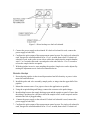
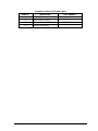
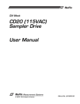
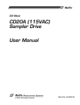
CLIF MOCK™
CS Sample Extractor
(24 VDC, 115 VAC)
User Manual
Manual No. 2295241-01, Rev. 01
Technical Support Contact Information:
Cameron Measurement Systems
14450 John F. Kennedy Blvd.
Houston, TX 77032
Phone: 1-800-654-3760; 281-582-9500
Fax: 281-582-9599
Clif Mock is a trademark of Cameron International Corporation (“Cameron”).
Copyright © 2008 Cameron International Corporation (“Cameron”). All
information contained in this publication is confidential and proprietary property of
Cameron. Any reproduction or use of these instructions, drawings, or photographs
without the express written permission of an officer of Cameron is forbidden.
All Rights Reserved.
Printed in the United States of America.
Manual No. 2295241-01, Rev. 01
May 2008
Table of Contents
Description ................................................................................................................. 5
Installation.................................................................................................................. 5
Direct Hookup ........................................................................................................ 5
Remote Hookup ..................................................................................................... 6
Maintenance .............................................................................................................. 6
May 2008
iii
CS Sample Extractor
CS Sample Extractor
iv
May 2008
Description
The CS Sample Extractor is designed to provide samples of flowing liquids in a costeffective and simple operation. The extractor obtains a proportion-to-flow sample from a
flow meter or measurement control system which provides a pulse to the solenoid actuation
valve. Upon actuation, the extractor connects the accumulation chamber with the flow
stream. In deactivation, the sample is discharged into the sample receptacle.
For dual-solenoid (two-coil) units, the pulse is routed to two actuation coils – a pulse to one
side allows the sample into sample chamber and a pulse to the other side allows the sample to
empty into the container.
The sample chamber can be adjusted to hold from approximately 0.5 cc to 4.0 cc per sample
to provide the required volume for analysis. (To achieve the maximum size sample, the
solenoid must remain energized in the open position for 1.5 to 2 seconds.)
The maximum operating pressure depends on the solenoid model used. An extractor with a
single solenoid (one coil and one set of wires) has a maximum operating pressure of 150 psi.
An extractor with a dual solenoid (two coils and two sets of wires) has a maximum operating
pressure of 500 psi.
The CS Sample Extractor is constructed of stainless steel and is available with Buna-N®
or Viton® seals.
Installation
The CS Sample Extractor is furnished as shown in the schematic in the back of this manual.
To complete installation, ensure that the customer has provided the following items:
•
Power supply (24 VDC or 115 VAC single phase)
•
Tubing and fittings as required for connecting the CS extractor to the sample
probe/stinger
•
Tubing and fittings as required for connecting the CS extractor to the receptacle
Direct Hookup
1. Ensure that the pipeline is shut in and depressurized, and that all electrical power is
turned off and locked out.
2. Install the probe and valve assembly, sample probe, or stinger in the upper half of the
pipeline.
3. Connect the CS Sample Extractor directly to the probe using any required tubing and or
fittings (Figure 1, page 6).
4. Connect the sample discharge port to the sample receptacle. Ensure that the tubing is
positioned at a decline to allow the sample to flow from the discharge port down to the
receptacle. This position helps reduce the risk for the tubing to become plugged.
May 2008
5
CS Sample Extractor
Figure 1—Direct hookup to a dual-coil solenoid
5. Connect the power supply to the solenoid. If a dual-coil solenoid is used, connect the
power supply to both coils.
6. Configure the pulse output of the measurement control system. If a single-coil solenoid is
used, energize the solenoid and hold it for 1.5 to 2 seconds, then release. If a dual-coil
solenoid is used, send a pulse to one side to collect the sample into the sample chamber,
wait 1.5 to 2 seconds, then send a second pulse to the other side for 1.5 to 2 seconds to
release the sample into the receptacle.
7. With the pipeline in service, start sampling the product. Sample size can be adjusted by
turning the adjustment screw clockwise/counterclockwise.
Remote Hookup
1. Ensure that the pipeline is shut in and depressurized and all electricity or power is also
turned off and locked out.
2. Install the probe and valve assembly, sample probe, or stinger into the upper half of the
pipeline.
3. Mount the extractor onto a 2-in. pipe as close to the application as possible.
4. Using the required tubing and fittings, connect the extractor to the probe/stinger.
5. Install tubing between the sample discharge port and the sample receptacle. Ensure that
the tubing is positioned at a decline to allow the sample to flow to the receptacle and to
minimize the risk of plugged tubing.
6.
Connect the power supply to the solenoid. If a dual-coil solenoid is used, connect the
power supply to both coils.
7. Configure the pulse output of the measurement control system. If a single-coil solenoid is
used, energize the solenoid and hold it for 1.5 to 2 seconds, then release. If a dual-coil
CS Sample Extractor
6
May 2008
solenoid is used, send a pulse to one side to collect the sample into the sample chamber,
wait 1.5 to 2 seconds, then send a second pulse to the other side for 1.5 to 2 seconds to
release the sample into the receptacle.
8. With the pipeline in service, start sampling the product. Sample size can be adjusted by
turning the adjustment screw clockwise or counterclockwise.
Maintenance
Note: The item numbers in the following procedure correspond to the numbers referenced in
the assembly diagram and list of components on page 9.
1. Disconnect the power supply or turn off the power and lock out the power supply to the
sampler.
2. Close off the sample probe or remove the sample probe from the pipeline to isolate all
flow from the sampler.
3. Remove the extractor from the solenoid.
4. Carefully remove the six mounting screws (item 6) that attach the accumulator to the CS
extractor body.
5. Inspect the O-ring (item 7) that seals between the accumulator and the body, and replace
if necessary.
NOTE: If the seal leaks, pressure could be built up behind the screws. Extreme care should be
exercised to ensure no one is hurt or injured by escaping pressure as the screws are
removed.
6. Remove the piston subassembly (items 5, 9, 10, and 15) and spring (item 11). If oil or
liquid has accumulated inside the accumulator (item 4), carefully clean out and remove
all liquid from the accumulator.
7. Remove the snap ring (item 10), seal retainer (item 15), and the seal (item 9) from the
piston.
8. Inspect the piston seal and accumulator for damage, and replace if required.
9. Unscrew the accumulator cap (item 13) from the accumulator.
10. Inspect the O-ring (item 12) on the accumulator and replace if necessary.
11. If oil or liquid has accumulated inside the accumulator cap, carefully clean out and
remove all liquid.
12. Inspect the lock nut (item 3) and adjustment screw (item 2) for damage or wear.
a. To replace the lock nut, unscrew the lock nut from the adjustment screw and screw
the replacement back onto the adjustment screw.
May 2008
7
CS Sample Extractor
b. To replace the adjustment screw, unscrew the lock nut from the adjustment screw,
and then unscrew the adjustment screw from the accumulator. Screw the replacement
adjustment screw into the accumulator and screw the lock nut back onto the screw.
c. Ensure that both the lock nut and adjustment screw are properly installed before
proceeding.
NOTE: If the lock nut is moved, ALL sample size settings will be eliminated and sample size
must be reset.
13. Lightly lubricate the internal parts with a light oil or mineral spirits.
14. Replace the accumulator cap onto the accumulator.
15. Replace the spring inside the accumulator, sliding it over the shaft of the adjustment
screw.
16. Replace the piston subassembly (items 5, 9, 10, and 15) inside the accumulator.
17. Carefully attach the accumulator to the CS extractor body (item 8) and replace the
mounting screws.
18. Reattach the extractor to the solenoid.
19. Open the sample probe to the line.
20. Reconnect the power to the sampler to resume sampling.
21. Reset the sample size, if necessary (if the lock nut was moved or replaced).
CS Sample Extractor
8
May 2008
ITEM NO.
May 2008
DESCRIPTION
1
PLUG, HEX, 1/4" SS
2
SCREW, ADJUSTMENT
3
NUT, HEX, 5/16-18 SS
4
ACCUMULATOR
5
PISTON, ACCUMULATOR
6
SCREW, SOCKET HEAD, 10-32 X 1/2 SS
7
O-RING, VITON #20 70 DURO
8
BODY, SAMPLER
9
SEAL, U-CUP, VITON
10
RING, SNAP, CS PISTON
11
SPRING, ACCUMULATOR
12
O-RING, VITON #019
13
CAP, ACCUMULATOR
14
TAG, SERIAL NUMBER
15
SEAL RETAINER, PISTON
9
CS Sample Extractor
CS SAMPLE EXTRACTOR SPARE PARTS
PART NUMBER
ITEM NO. *
DESCRIPTION
7
O-RING, VITON #20 70 DURO
9A-50108500097
9
SEAL, U-CUP, VITON
9A-50108500120
10
RING, SNAP, CS PISTON
9A-50108500089
12
O-RING, VITON #019
9A-50142200462
*See assembly drawing on previous page for location.
CS Sample Extractor
10
May 2008
WARRANTY - LIMITATION OF LIABILITY: Seller warrants only title to the products,
software, supplies and materials and that, except as to software, the same are free
from defects in workmanship and materials for a period of one (1) year from the date
of delivery. Seller does not warranty that software is free from error or that software
will run in an uninterrupted fashion. Seller provides all software "as is". THERE ARE
NO WARRANTIES, EXPRESS OR IMPLIED, OF MERCHANTABILITY, FITNESS
FOR A PARTICULAR PURPOSE, OR OTHERWISE WHICH EXTEND BEYOND
THOSE STATED IN THE IMMEDIATELY PRECEDING SENTENCE. Seller's liability
and Buyer's exclusive remedy in any case of action (whether in contract, tort, breach
of warranty or otherwise) arising out of the sale or use of any products, software,
supplies, or materials is expressly limited to the replacement of such products,
software, supplies, or materials on their return to Seller or, at Seller's option, to the
allowance to the customer of credit for the cost of such items. In no event shall Seller
be liable for special, incidental, indirect, punitive or consequential damages. Seller
does not warrant in any way products, software, supplies and materials not
manufactured by Seller, and such will be sold only with the warranties that are given
by the manufacturer thereof. Seller will pass only through to its purchaser of such
items the warranty granted to it by the manufacturer.