1
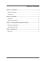
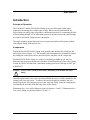
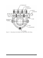
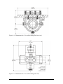
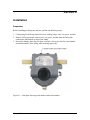
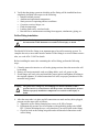
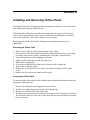
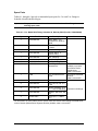
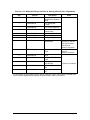
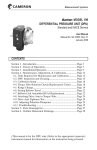
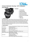
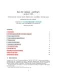
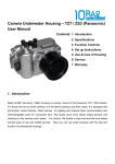
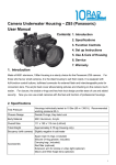
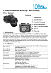
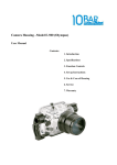
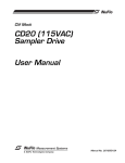
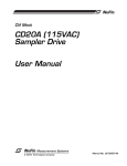
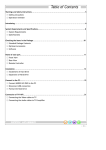
CLIF MOCK
TM
Model 5030
Orifice Fitting
User Manual
Manual No. 25165003, Rev. B
© 2007 Cameron International Corporation (“Cameron”). All information
contained in this publication is confidential and proprietary property of Cameron.
Any reproduction or use of these instructions, drawings, or photographs without
the express written permission of an officer of Cameron is forbidden.
All Rights Reserved.
Printed in the United States of America.
Manual No. 25165003, Rev. B
January 2007
Table of Contents
Section 1—Introduction .....................................................................................5
Principle of Operation........................................................................................5
Components......................................................................................................5
Section 2—Installation .......................................................................................9
Preparation........................................................................................................9
Orifice Fitting Installation .................................................................................10
Section 3—Installing and Removing Orifice Plates ....................................... 11
Removing an Orifice Plate...............................................................................11
Inserting an Orifice Plate .................................................................................11
Section 4—Maintenance...................................................................................13
Spare Parts .....................................................................................................14
January 2007
iii
iv
January 2007
Section 1
Introduction
Principle of Operation
The Clif Mock™ Model 5030 Orifice Fitting secures an orifice plate in the proper
position for measuring flow within a pipe or tube. When correctly positioned in the
orifice fitting, an orifice plate will produce a differential pressure by constricting the flow
of fluid passing through it. The differential pressure is measured across the plate through
two taps located on the fitting near the constriction.
The single chamber design allows the user to inspect and replace orifice plates without
removing the fitting from the flow line.
Components
Within the Model 5030 Orifice Fitting is an assembly that includes the sealing bar and
orifice plate carrier (Figure 1.1). This assembly allows maintenance personnel to remove
the sealing bar, orifice plate carrier, the orifice plate, and plate seal in a single step.
The Model 5030 Orifice Fitting is a weld-by-weld fitting available in 2 in. and 3 in.
diameters and in two pipe thicknesses (Schedule 40 and Schedule 80). The orifice fitting
is rated for ANSI Class 600 with a maximum working pressure of 1480 psi at 100°F per
ASME B16.5.
Warning
!
Always relieve system pressure before attempting to disassemble the orifice
fitting.
The orifice plate fitted with a seal is positioned inside the carrier, which is attached to the
sealing bar by two cap screws. To remove the carrier/sealing bar assembly, the user
simply loosens the four clamping screws at the top of the fitting, slides the clamping bar
out, and lifts the assembly from the body of the orifice fitting.
Dimensions for a 2-in. orifice fitting are shown in Figures 1.2 and 1.3. Dimensions for a
3-in. orifice fitting are shown in Figures 1.4 and 1.5.
January 2007
5
Figure 1.1—Nomenclature for the Model 5030 single-chamber orifice fitting
6
January 2007
Figure 1.2—Dimensions for a 2-in. orifice fitting (flow line view)
Figure 1.3—Dimensions for a 2-in. orifice fitting (side view)
January 2007
7
Figure 1.4—Dimensions for a 3-in. orifice fitting (flow line view)
Figure 1.5—Dimensions for a 3-in. orifice fitting (side view)
8
January 2007
Section 2
Installation
Preparation
Before installing the fitting into the line, perform the following steps:
1. Clean piping of all foreign material such as welding chips, scale, oil, grease, and dirt.
2. Remove all foreign matter such as scale, oil, grease, and dirt from the fitting line
connections and internal cavities of the fitting.
3. Record the fitting's plate data for future reference. Always provide the serial number
and model number of the fitting when ordering spare parts.
Figure 2.1—Data plate showing serial number and model number
January 2007
9
4. Verify that the piping system in which the orifice fitting will be installed has been
adequately designed with respect to the following:
• Internal/external pressure
• Ambient and operational temperatures
• Static pressure in operating and test conditions
• Corrosion, erosion, fatigue, etc.
• Fluid decomposition
• Loading from traffic, wind and earth
• Reaction forces and moments resulting from supports, attachments, piping, etc.
Orifice Fitting Installation
Warning
!
The orifice fitting may contain fluid under high pressure. Failure to comply with
the instructions in this document can result in serious injury or death.
The Model 5030 Orifice Fitting is an important part of an orifice metering system. To
complete the unit, a meter tube must be attached. If the fitting is received without a meter
tube, see code AGA-3-1985 for details.
Before installing the meter tube containing the orifice fitting, perform the following
steps:
1. Clean the meter tube interior as well as the piping sections where the meter tube will
be installed.
2. Remove all foreign materials such as welding debris, scale, oil, grease or dirt.
3. If end flanges are used, select and install the proper gaskets and tighten all bolting to
the required tightness. If welded connections are used, use proper procedures for the
materials being joined.
Warning
!
The gasket seal, sealing bar, and clamping bar must be installed so that a
pressure barrier is created between the line pressure and atmospheric pressure.
Failure to properly install these components can result in serious injury or
death.
4. After the meter tube is in place and all connections are made and any holes plugged,
pressure-test the meter tube as follows:
a. Tighten the orifice fitting clamping bar screws to 40 ft-lb of torque.
b. Hydrostatically pressure test in accordance with applicable piping code ASME
B31.3. Before initiating the test, verify that there is no orifice plate in the fitting.
c. Check for leaks at the sealing bar gasket and at all threaded connections on the
orifice fitting.
10
January 2007
Section 3
Installing and Removing Orifice Plates
The Model 5030 Orifice Fitting design allows an operator to install or remove the orifice
plate while minimizing line shutdown time.
Within the orifice fitting is an assembly that includes the sealing bar and orifice plate
carrier. This sealing bar/orifice plate carrier assembly allows maintenance personnel to
remove the sealing bar, orifice plate, and plate seal at one time.
The design of the Model 5030 Orifice Fitting prevents spillage in liquid service
applications.
Removing an Orifice Plate
1. Depressurize or shut in the line supporting the orifice fitting.
2. Once pressure in the plate holder is reduced to ambient pressure, remove the sealing
bar/orifice plate carrier assembly, containing the orifice plate, from the fitting.
3. Loosen the fasteners on the clamping bar two turns.
4. Lightly tap the sealing bar to break the gasket seal.
5. Slide out the clamping bar.
6. Lift out the sealing bar/orifice plate carrier from the orifice fitting body.
7. Remove the sealing bar gasket.
8. Remove the orifice plate and orifice plate seal from the sealing bar/orifice plate
carrier.
9. Remove the orifice plate seal from the orifice plate.
Inserting an Orifice Plate
To insert an orifice plate into the orifice fitting without removing the fitting from the line,
perform the following steps.
1.
2.
3.
4.
Remove the sealing bar and clamping bar from the body.
Install a new sealing bar gasket onto the orifice fitting body.
Install a new orifice seal onto the orifice plate.
Install the orifice plate and seal assembly into the plate carrier, taking into account the
flow direction of the line. This can be done using the dowel pin located in the sealing
bar as a reference.
January 2007
11
Caution
!
Failure to install the orifice plate and orifice gasket assembly in a direction
properly oriented with the direction of flow will result in measurement error
and a possible loss of revenue.
5. Lower the plate carrier assembly into the orifice fitting, while aligning the dowel pin
hole with the dowel pin, until the sealing bar/plate holder comes in full contact with
the sealing bar gasket.
6. Install the clamping bar.
7. Tighten each of the clamping bar fasteners to 40 ft-lb of torque.
The Model 5030 Orifice Fitting is now ready for final pressurization and operation.
12
January 2007
Section 4
Maintenance
Under normal measurement conditions, the Model 5030 Orifice Fitting will require no
maintenance. However, Cameron recommends a periodic inspection of the orifice fitting
at an interval established by the measurement supervisor.
The inspection should include a check of the plate holder for vandalism, or other
inadvertent damage and well as a check for tightness of fasteners and connectors to
ensure that the corrosion and tolerance dimensions of the fitting are not exceeded.
January 2007
13
Spare Parts
Tables 4.1 though 4.4 provide recommended spare parts for 2 in. and 3 in. fittings in
Schedule 40 and Schedule 80 pipe.
Important
Always provide the serial number and model number of the fitting when
ordering spare parts.
Table 4.1—2-in. Model 5030 Fitting. Schedule 40, Weld-by-Weld (Part No. 50306000440)
Qty.
1
Part No.
50306000442
Description
Body, Mach., 2-in.
Schedule 40, Weld-byWeld
Pin, Sealing Bar
Locator
Pin, Carrier Alignment
Carrier, Mach , 2”
Orifice Fitting
Bar, Clamping
Bar, Sealing
Gasket, Sealing Bar
Seal Ring, Nitrile, 2”,
Schedule 40
1
50316000438
1
1
50316000439
50316000444
1
1
1
1
50316000445
50316000446
50316000447
9910100
1
TBD
2-in. Universal Orifice
Plate
2
2
50025400759
50316000437
4
50316000448
2
50316000465
3
0199-0192C
Rivet
Bolt, Hex HD, 3/8-16 x
1 SS
Screw, Clamping, ½-13
x 1 ¼ SQ HD Half-Dog
Washer, Split Lock, 3/8
SS
Plug, Pipe, ½ “ MNPT
ST
Notes
Other materials
available on request.
See Orifice Plates
data sheet at
www.c-a-m.com/flo.
See Orifice Plate data
sheet at
www.c-a-m.com/flo.
Common to all fittings
For information on orifice plates, see the Orifice Plates and Orifice Plate Sealing Units data sheet
on the Cameron (Measurement Systems Division) website, www.c-a-m.com/flo.
14
January 2007
Table 4.2—2-in. Model 5030 Fitting, Schedule 80, Weld-by-Weld (Part No. 50306000461)
Qty.
1
Part No.
50306000459
Description
Body, Mach., 2-in.
Schedule 80, Weld-byWeld
Pin, Sealing Bar
Locator
Pin, Carrier Alignment
Carrier, Mach, 2”
Orifice Fitting
Bar, Clamping
Bar, Sealing
Gasket, Sealing Bar
Seal Ring, Nitrile, 2”,
Schedule 80
1
50316000438
1
1
50316000439
50316000444
1
1
1
1
50316000445
50316000446
50316000447
9910101
1
TBD
2-in. Universal Orifice
Plate
2
2
50025400759
50316000437
4
50316000448
2
50316000465
3
0199-0192C
Rivet
Bolt, Hex HD, 3/8-16 x
1 SS
Screw, ½-13 x 1 ¼ SQ
HD Half-Dog
Washer, Split Lock, 3/8
SS
Plug, Pipe, ½ “ MNPT
ST
Notes
Other materials
available on request.
See Orifice Plates
data sheet at www.ca-m.com/flo.
See Orifice Plates
data sheet at
www.c-a-m.com/flo.
Common to all fittings
For information on orifice plates, see the Orifice Plates and Orifice Plate Sealing Units data sheet
on the Cameron (Measurement Systems Division) website, www.c-a-m.com/flo.
January 2007
15
Table 4.3—3-in. Model 5030 Fitting, Schedule 40, Weld-by-Weld (Part No. 50306000450)
Qty.
1
Part No.
50306000452
Description
Body, Mach., 3-in.
Schedule 40, Weld-byWeld
Pin, Sealing Bar
Locator
Pin, Carrier Alignment
Carrier, Mach, 3”
Orifice Fitting
Bar, Clamping
Bar, Sealing
Gasket, Sealing Bar
Seal Ring, Nitrile, 3”,
Schedule 40
1
50316000438
1
1
50316000439
50316000454
1
1
1
1
50316000455
50316000456
50316000457
9910102
1
TBD
3-in. Universal Orifice
Plate
2
2
50025400759
50316000437
4
50316000448
2
50316000465
3
0199-0192C
Rivet
Bolt, Hex HD, 3/8-16 x
1 SS
Screw, ½-13 x 1 ¼ SQ
HD Half-Dog
Washer, Split Lock, 3/8
SS
Plug, Pipe, ½ “ MNPT
ST
Notes
Other materials
available on request.
See Orifice Plates
data sheet at
www.c-a-m.com/flo.
See Orifice Plate data
sheet at
www.c-a-m.com/flo.
Common to all fittings
For information on orifice plates, see the Orifice Plates and Orifice Plate Sealing Units data sheet
on the Cameron (Measurement Systems Division) website, www.c-a-m.com/flo.
16
January 2007
Table 4.4—3-in. Model 5030 Fitting, Schedule 80, Weld-by-Weld (Part No. 50306000462)
Qty.
1
Part No.
50306000460
Description
Body, Mach., 3-in.
Schedule 80, Weld-byWeld
Pin, Sealing Bar
Locator
Pin, Carrier Alignment
Carrier, Mach, 3”
Orifice Fitting
Bar, Clamping
Bar, Sealing
Gasket, Sealing Bar
Seal Ring, Nitrile, 3”,
Schedule 80
1
50316000438
1
1
50316000439
50316000454
1
1
1
1
50316000455
50316000456
50316000457
9910103
1
TBD
3-in. Universal Orifice
Plate
2
2
50025400759
50316000437
4
50316000448
2
50316000465
3
0199-0192C
Rivet
Bolt, Hex HD, 3/8-16 x
1 SS
Screw, ½-13 x 1 ¼ SQ
HD Half-Dog
Washer, Split Lock, 3/8
SS
Plug, Pipe, ½ “ MNPT
ST
Notes
Other materials
available on request.
See Orifice Plates
data sheet at
www.c-a-m.com/flo.
See Orifice Plate data
sheet at
www.c-a-m.com/flo.
Common to all fittings
For information on orifice plates, see the Orifice Plates and Orifice Plate Sealing Units data sheet
on the Cameron (Measurement Systems Division) website, www.c-a-m.com/flo.
January 2007
17
18
January 2007
WARRANTY - LIMITATION OF LIABILITY: Seller warrants only title to the
products, software, supplies and materials and that, except as to software, the
same are free from defects in workmanship and materials for a period of one (1)
year from the date of delivery. Seller does not warranty that software is free from
error or that software will run in an uninterrupted fashion. Seller provides all
software "as is". THERE ARE NO WARRANTIES, EXPRESS OR IMPLIED, OF
MERCHANTABILITY, FITNESS OR OTHERWISE WHICH EXTEND BEYOND
THOSE STATED IN THE IMMEDIATELY PRECEDING SENTENCE. Seller's
liability and Buyer's exclusive remedy in any case of action (whether in contract,
tort, breach of warranty or otherwise) arising out of the sale or use of any
products, software, supplies, or materials is expressly limited to the replacement
of such products, software, supplies, or materials on their return to Seller or, at
Seller's option, to the allowance to the customer of credit for the cost of such
items. In no event shall Seller be liable for special, incidental, indirect, punitive or
consequential damages. Seller does not warrant in any way products, software,
supplies and materials not manufactured by Seller, and such will be sold only
with the warranties that are given by the manufacturer thereof. Seller will pass
only through to its purchaser of such items the warranty granted to it by the
manufacturer.