1
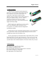
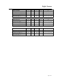
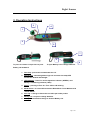
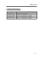
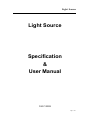
Light Source Light Source Specification & User Manual 2009 VERB Page 1 of 7 Light Source 1.1 Description Light Source is a handy tool and instrument to provide you several different wavelengths to test the fiber equipment in the optical network and FTTx construction. Light Source is ideal for field or laboratory testing of optical communication system at 850 nm for datacom testing, 1310 nm / 1550 nm. Light Source features zero warm up, superb productivity and is easy to use with pocket-size and rugged and handy design. With LC patch cord , Light Source can be used for all the most widespread fiber interfaces such as LC connector. It is suitable to test both Singlemode and Multimode cables. Internally there is also a specifically designed power circuit included; the APC ( Auto Power Control ) circuit provides steady power which avoids unstable laser output when the battery is low. The LD output signal can be switched CW or Pulse Mode 270 Hz / 2 KHz Modulated Mode to simulate signal transmission. There is a dust proof cap which will prevent dust from getting into the inside of the LD connector. The cap also helps evade incidental exposure of the laser directly into your eyes. 1.2 Features Pocket-size & rugged & handy design. Needless to pre-warm-up time. Interchangeable SFP Module design with LC connector. Flexible to change any wavelength. High stability of the Output Power. Page 2 of 7 Light Source Excellent & stable output wavelength. Excellent re-connection repeatability. Low Voltage Battery warning signal in LED. Compatible to LC Connectors. Economic type and easy to use. Operates in CW ( Continuous Wave) or Pulse Mode 270 Hz / 2 KHz The dust-proof design keeps fiber connectors clean Two AAA-size alkaline batteries LED indicator for Power, Battery Low indicators 1.3 Application Maintenance CATV / Telecom / FTTH in Singlemode or Multimode fiber optical fiber network. Standard laboratories. High throughput quality assurance. 2. Specification Laser Class Wavelength (nm) Mode Class 1 850, 1310, 1550 CW / Pulse Mode 270 Hz / 2 KHz Battery Type AAA 1.5 V x 2 LED Indicator Power On ( GREEN ) / Battery Low ( RED) Output Power Accuracy +/- 0.2 dB Output Power Stability ( 1 HR ) +/- 0.05 dB Operating Temp. 0℃ ~ 50℃ Storage Temp. 0℃ ~ 70℃ Page 3 of 7 Light Source MOD-VC0850L VCSEL Output Power Min. Typ. Center Wavelength λC Min. Typ. 1290 Min. DFB LD Output Power -3 Center Wavelength λC 1530 Spectral Width Δλ @ 25℃ 62.5 / 125 µm fiber nm @ 25℃ 62.5 / 125 µm fiber 0.85 nm @ 25℃ 62.5 / 125 µm fiber Max. Unit Note dBm @ 25℃ 9 / 125 µm fiber 1330 nm @ 25℃ 9 / 125 µm fiber <4 nm @ 25℃ 9 / 125 µm fiber Max. Unit -5 1310 Spectral Width Δλ MOD-DF1550L dBm 850 Spectral Width Δλ FP LD Output Power Note -5 Center Wavelength λC MOD-FP1310L Unit Max. Typ. 1550 Note dBm @ 25℃ 9 / 125 µm fiber 1570 nm @ 25℃ 9 / 125 µm fiber <1 nm @ 25℃ 9 / 125 µm fiber Page 4 of 7 Light Source 3. Operating Instructions 3 4 1 2 5 7 8 6 To press to release Linchpin then to push To open Battery Lid to change batteries. Battery Lid backward. 1. Dust Cap : prevent dirt contaminates the LD . 2. SFP Module : Interchangeable single LC connector hot swap SFP module for identical wavelength. 3. LED Indicator : Power On and In Operation indicator ( GREEN ) and Battery Low Warning indicator ( RED) . 4. Button : pressing to Turn On / Turn Off the LD emitting. 5. Mode Switch : to select CW Continuous Wave Mode / Pulse Mode 270 Hz / 2 KHz Switch. 6. Pen Clip : a design to fasten the tool while put inside pocket. 7. Battery Lid : to open to change batteries. 8. Linchpin : a mechanical design to lock the Battery Lid. Page 5 of 7 Light Source 1. The Light Source is powered by two pieces 1.5 V AAA batteries. 2. To inset Plug-In Module inside the Light Source Main Frame, press Button and check if the LED is GREEN. 3. To press Button to Turn Off Light Source. 4. Lift the front of the Dust Cap and insert on end of the fiber connector to the LC connector or directly insert to a connector of the fiber or LC patch cord. 5. Switch to select to CW Mode or Pulse Mode 270 Hz / 2 KHz. 6. To press the Button to Turn On Light Source. LED Indicator now is GREEN while the Light Source is in operation. 7. To press the Button second time to Turn Off Light Source. The LED Indicator will be turned off. 8. When the LED Indicator is RED, this means batteries are almost drained out and in low voltage status. You will need to replace the batteries right away to keep the tool in right functions. 9. Do not touch the Light Source connector to avoid dirt into the connector. 10. Keep the Dust Cap closed all the time while the Light Source is not in use. 11. With proper cleaning tools to clean the Light Source SFP connector before testing so that to obtain best results and keep the Light Source service longer. 4. Maintenance This tool requires no maintenance other than periodic battery charges. Like any other electronic equipment, this tool should be kept away from water, high damp, dust, electricity, and environments of extreme temperature. Do not drop this tool on hard surface. Modifying internally any of this tool components can cause a malfunction and will invalid the manufacturer’s warranty. Page 6 of 7 Light Source 5. Ordering Information: Part Number Description RP-MF1200 Light Source Main Frame MOD-VC0850L VCSEL 850 nm plug-in LC module MOD-FP1310L FP LD 1310 nm plug-in LC module MOD-FP1550L FP LD 1550 nm plug-in LC module Page 7 of 7