1
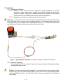
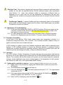
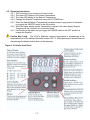
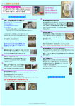
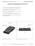
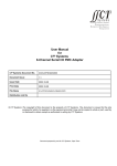
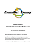
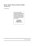
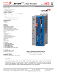
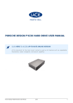
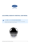
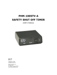
VTAC
SU-A750
Variable Tem perature
AC Controller Heater Controller
and Pow er Supply
SU-200 Substrate Heater
OPERATION MANUAL
220V
www.meivac.com
SAFETY
THIS CONTROLLER GENERATES VOLTAGES THAT ARE DANGEROUS AND MAY BE FATAL.
OBSERVE EXTREME CAUTION WHEN WORKING WITH THIS EQUIPMENT.
SERVICING SAFETY
Servicing should be done by qualified personnel aware of the electrical hazards.
Maintenance may require removing the instrument cover with the power on.
Do not ground yourself or work under wet or damp conditions.
Caution notes in the text indicate procedures to be followed to avoid possible damage to equipment
Voltage, Removing the VTAC cover may expose the User to Hazardous voltages. All
electrical power to the VTAC circuits and from the heater system must be disconnected
before removing the cover from the enclosure or disconnecting any wiring.
Fire/Explosion, Disconnect all electrical power from the VTAC prior to removing the cover
from the enclosure. Failure to do so may result in sparks that could cause a fire or an
explosion.
Heat, Do not obstruct air circulation to the enclosure. Overheating and possible fire may
occur.
Weight Imbalance, The VTAC enclosure has a significant weight imbalance front to rear.
Use caution in lifting, handling, mounting, or installing this case.
Electrical Code, This product is supplied with Input and Output connectors and power cables
suitable for use with the specified MeiVac SU-200 substrate heaters (See specification
table Section 1.2). Users who substitute cables or connectors of different sizes or
capacities do so at their own risk and are responsible for determining that any such
substitutions are suitable for the purpose selected and meet all relevant local and national
codes.
Feedthrough capacity, A vacuum feedthrough that is adequately sized for the VTAC’s
specified power levels and thermocouple signals must be utilized. Such feedthroughs are
available from MeiVac as extra cost Options.
Process Advisory: Glow Discharge
A Plasma discharge may be created around the portion of the feedthrough and conductors
located within the vacuum chamber. Adequate shielding may be required to minimize
interference with process conditions in the chamber.
Caution, The VTAC equipment described in this Manual is designed, factory programmed
and tested for use with the MeiVac SU-200 substrate heaters specified herein. Modifying
or re-programming this VTAC equipment in any manner other than described in this Manual,
or using it with any products other than the specified substrate heaters, is done at the
User’s sole risk. Such modification, re-programming and/or use with other products may
damage the VTAC and/or the product it’s being used with and void their respective
warranties.
1/17
Table of Contents
Page
Safety , Cautionary Notes. ········································································· 1
1.0
1.1
1.2
1.3
1.4
Introduction ··················································································· 3
Description of the VTAC SU-A750 ························································ 3
Specifications ··················································································· 3
Standard Features ············································································ 3-4
User Supplied Items ·········································································· 4
2.0
Receiving, Installation and Maintenance ·············································· 4
2.1 Receiving and Inspection ···································································· 4
2.2 Installation ······················································································· 5-6
2.3 Maintenance & Troubleshooting ··························································· 6
3.0
Principles of Operation····································································· 6
4.0
Operation ······················································································ 6
4.1 Setting up the controller on start-up ··············································· 6
4.2 Operating Instructions································································· 7
4.3 Programming Optional Ramp Function ·········································· 8-10
4.4 Starting a RAMP Cycle from the Home Page ·································· 10-11
4.5 Programming Returning to the STANDARD function ························· 12-13
4.6 Other Watlow Controller Capabilities ············································· 13
5.0
Options ························································································· 14
6.0
System Schematic ·········································································· 15
7.0
Parts List······················································································· 16
8.0
Factory Service ············································································· 16
Attachments, Watlow, EZ-Zone PM User’s Manual, 0600-0058-0000 Rev. C
Table
1
2
3
4
5
Description
Page
Specifications: VTAC SU-A750 for use with MeiVac SU-200 heater······ 3
Programming Ramp Function & Re-locking the Controller Program ······ 9-10
Returning to Standard Function & Re-locking the Controller Program ··· 12-13
Optional Equipment /Accessories ·················································· 14
Replacement Parts List ································································ 16
Figure
1
2
3
4
5
Typical Heater assembly ······························································ 5
Controller front panel ··································································· 7
Optional Vacuum Power and Thermocouple Feedthrough ················· 14
Typical in-vacuum heater assembly with options······························· 14
System Schematic ······································································ 15
2/17
1.0 Introduction: The SU-A750 VTAC is designed to control MeiVac SU-200 Substrate Heaters.
1.1 PRODUCT DESCRIPTION
The VTAC variable temperature AC controller provides a closed loop solution to drive and
control the MeiVac SU-200 series substrate heaters. There is a PID controller at the heart of
this unit with auto tuning capability for fast and efficient control of your thermal process. The
controller drives the heater using SSR technology which regulates the voltage applied to the
heater. Temperature feedback is relayed through a Type K thermocouple which provides for the
closed loop control.
1.2 Table 1. Specifications: VTAC SU-A750-220V for use with MeiVac SU-200 heater
Controller model
Power Output, Max
Input Voltage
Input Current
Output Voltage
Input connector or cord length
Output conductor length and
connector
Weight
Dimensions
Fuse
Thermocouple (not supplied)
SU-A750-220V
1000 W
220 VAC 50 / 60 Hz
≥6A
< 60 VAC
Connector European CEE 7/7
Cord length 6 ft
10 ft Standard. Optional length
available upon request
Output connectors,
(2) Altech CB4/1
50 pounds (23 kg)
6.5” (165 mm) tall
10” (254 mm) wide
14’’ (356 mm) deep
1 A & (2) 6 A
Type K
1.3 Standard Features and Benefits:
1.3.1 Advanced PID Control Algorithm
- Provides auto tuning for fast, efficient start ups
- Allows tighter control of thermal processes
1.3.2 Variable Set-point
- Temperature controlled to user selected setpoint
- Setpoint can range from room temperature to 950º C
1.3.3 Programmable Ramp
- User defined ramps for rate-of-rise sensitive thermal processes
- Ramp intervals designated in minutes or hours
1.3.4 Program Lock-out
- Protection against unintended changes
- Secures process parameters from unauthorized users
3/17
1.3.5 Over-temp Alarm
- Sonalert alarm sounds if operating temperature exceeds the programmed setpoint
by 30º C (86º F)
- Corrective action required to silence the alarm
1.3.6 Air Cooled
- Forced air cooling integrated into the unit to provide protection against overheating
1.4 The User must supply the following, which are available from MeiVac as Extra Cost
Options. See section 5.0
1.4.1 Power and Thermocouple vacuum feedthrough appropriately sized for the VTAC output
power and thermocouple type.
1.4.2 Electrical wiring to connect the vacuum feedthrough to the substrate heater in the
vacuum system
1.4.3 Thermocouple
1.4.4 Thermocouple signal wiring from the thermocouple to the VTAC controller
2.0 Receiving, Installation and Maintenance
2.1 Receiving and Inspection
2.1.1 On receipt, the unit should be unpacked and checked for damage such as loose parts
or dents and scratches on the enclosure or front and rear panels.
2.1.2 If damage to the shipping carton is evident on receipt, the User should request that
shipper’s agent be present when the unit is unpacked to confirm visible shipping
damage that might be claimed.
2.1.3 If necessary, file claims for damage with the shipper.
2.1.4 If damage appears to be significant, contact MeiVac for product repair or return
instructions.
2.1.5 If return to MeiVac is required, repackage and ship in original shipping cartons, when
possible.
Caution, Do not attempt to operate a VTAC if physical damage is evident. When possible,
retain shipping cartons and packing material should subsequent return of the unit to
MeiVac become necessary.
4/17
2.2 Installation
2.2.1 Mechanical Installation
2.2.1.1 Because of the VTAC enclosure’s weight and weight imbalance, it must be
mounted on a flat surface that is properly reinforced and capable of carrying the
enclosure’s weight. Anchoring or otherwise securing the enclosure to its mounting
surface must be in accordance with all local codes and regulations.
2.2.1.2 Adequate air circulation must be provided to the enclosure.
Warning, It is very important to insert the thermocouple all the way into the substrate heater
block and make sure it cannot come out during operation. If the thermocouple comes out
during operation severe damage to the substrate heater can occur. If the thermocouple breaks,
the controller will shut down the system and the Sonalert will sound.
Figure 1. Typical Heater assembly. (See Options page for additional information)
2.2.2 Electrical Installation
Confirm that the VTAC is connected to a power source operating at the required voltage,
and specified input current.
Caution: The power supply may be damaged if it is connected to the wrong supply voltage
or the wiring is incorrect. Before applying power, make sure that the input voltage specified
on the Input Ratings Label on the rear panel of the enclosure corresponds to the voltage of
your system.
5/17
Electrical Code, This product is supplied with Input and Output connectors and power cables
suitable for use with the specified MeiVac SU-200 substrate heaters (See specification
table Section 1.2). Users who substitute cables or connectors of different sizes or
capacities do so at their own risk and are responsible for determining that any such
substitutions are suitable for the purpose selected and meet all relevant local and national
codes
Feedthrough Capacity, A vacuum feedthrough that is adequately sized for the specified
power levels and thermocouple signals must be utilized. Such feedthroughs are available
from MeiVac as extra cost Options.
2.3 Maintenance & Troubleshooting
2.3.1 In the event that toggling the POWER or HEATER switches ON does not power up the
controller or heater, check the fuses (after disconnecting input power) located on the
back panel of its main enclosure.
2.3.2 For other maintenance and troubleshooting information Refer to System Schematic
(Section 6.0), Replacement parts list (Section 7.0) and/or attached Watlow Manual.
3.0 Principles of operation:
At the heart of the MeiVac VTAC heater power supply and temperature controller is a
Proportional–Integral–Derivative (PID) controller. This controller provides adaptive tuning for
tighter control and auto-tune for faster start-ups.
A PID controller is a generic control loop feedback mechanism widely used in industrial control
systems. A PID controller attempts to correct the difference between a measured Process
Variable and a desired Setpoint by calculating and then outputting a corrective action that can
adjust the process accordingly and rapidly, to keep the difference minimal.
4.0 Operation
The VTAC utilizes a Watlow Temperature Controller that has been programmed and tested at
the factory for use as a setpoint type controller with the SU-200 substrate heater specified in this
Manual. The controller will drive the heater at full power until the desired setpoint is achieved.
However, certain applications may require slower ramping of the temperature for their process.
See Sections 4.3 and 4.4 for the Programmable RAMP function.
4.1 Setting up the controller on start-up: Reference Watlow EZ-ZONE Panel Figure on the next page
4.1.1 Apply power to the controller by toggling the POWER switch on the front panel to the
ON position.
4.1.2 The temperature controller display will light up.
4.1.3 Press the ADVANCE key
should read “AUTO”.
. The lower display should read “C.r7I”. The upper display
4.1.4 If the upper display does not read “AUTO”, then push the UP-DOWN keys
change the display from “MANUAL” to “OFF” to “AUTO”.
4.1.5 When “AUTO” is displayed, press the INFINITY
6/17
key.
to
4.2 Operating Instructions:
4.2.1 The Controller is now running in the Auto mode.
4.2.2 The upper LED Display is the Heater Temperature.
4.2.3 The lower LED display is the Setpoint Temperature.
4.2.4 Change the Setpoint Temperature using the UP-DOWN keys.
4.2.5 When the desired Setpoint Temperature has been entered, apply power to the heater
by toggling the HEATER switch to the ON position.
4.2.6 When the upper display Heater Temperature is equal to the lower display Setpoint
Temperature, the controller is in the control mode.
4.2.7 It will remain in that state until you toggle the POWER switch to the OFF position or
change the Setpoint.
Caution Max Temp: The VTAC’s Maximum setpoint temperature is programmed at the
temperature limit of the MeiVac Substrate Heaters, 950 ºC. Reprogramming to exceed this limit
may damage the heater module and void the warranty.
Figure 2. Controller front Panel
7/17
Safety Feature: If the new Setpoint you input is 30 ºC lower than the Heater temperature, the
Sonalert alarm will sound indicating an over-temperature condition. This is a safety feature to alert
you that the substrate Heater temperature is significantly higher than the Setpoint temperature. The
alarm will turn off automatically when the substrate Heater temperature is less than 30 ºC above the
Setpoint temperature. To silence the alarm prior to that, toggle the HEATER switch to the OFF
position until the Heater temperature is less than 30 ºC above the new Set-point, then toggle the
HEATER switch back to the ON position. The temperature controller will then control to the new
Setpoint.
4.3 RAMP Program Programming Optional Ramp Function:
The VTAC model SU-A750 has the ability to be programmed so that the Heater temperature
can be ramped to the desired Setpoint temperature over a user defined period of time. This
feature could be used if the wafer or substrate might be damaged by a rapid temperature
increase. If you need a slower rate of rise for your wafer or substrate, it will be necessary to
change the program. The program allows you to control the rate of rise in degrees per minute
or hour. When the VTAC model SU-A750 Supply was shipped from our factory, this
programming feature was locked out. To use the RAMP mode you will need to unlock the
controller and change the program. Below is a step by step method to unlock and re-program
the controller for the RAMP feature.
Warning: After you unlock the controller and make changes to the program, you need to
relock the controller to maintain security.
8/17
Table 2. Programming
the RAMP Function
With both the POWER and HEATER switches in the OFF position, toggle the POWER switch ON, the
temperature controller display will light up. (This is called the Home Page)
9/17
4.4 Starting a RAMP Cycle from the Home Page
4.4.1 Push the ADVANCE key
and the lower display will read “Cr71”.
4.4.2 Press the DOWN arrow key
until the upper display reads “OFF”.
4.4.3 Press the INFINITY key
.
4.4.4 Toggle the HEATER switch to the ON position.
4.4.5 Push the ADVANCE key
and the lower display will read “Cr71”.
4.4.6 Press the DOWN arrow key
until the upper display reads “AUTO”.
4.4.7 Press the Infinity key
.
4.4.8 This will start the heat cycle and you will see in the top display, flashing “r.rt” and heater
temperature. The bottom display will be flashing “Attn” and the temperature set point.
10/17
4.4.9 If needed you can set the temperature set point with the UP/DOWN Arrow Keys. The
temperature of the heater will ramp per your Rate of Rise setting until it reaches the
desired Setpoint. When the heater temperature is equal to the Setpoint temperature,
both displays will stop blinking. The controller is now in the control mode. It will remain
in that state until you toggle the POWER or HEATER switch to the OFF position or
change the setpoint.
4.4.10 When you want to start a new heat cycle, start from 4.4.1.
Caution: You must complete the off/auto sequence in-order to reset the ramping feature.
Safety Feature: If the new Setpoint you input is 30 ºC lower than the Heater temperature, the
Sonalert alarm will sound indicating an over-temperature condition. This is a safety feature to alert
you that the substrate Heater temperature is significantly higher than the Setpoint temperature. The
alarm will turn off automatically when the substrate Heater temperature is less than 30 ºC above the
Setpoint temperature. To silence the alarm prior to that, toggle the HEATER switch to the OFF
position until the Heater temperature is less than 30 ºC above the new Setpoint, then toggle the
HEATER switch back to the ON position. The temperature controller will then control to the new
Setpoint.
Caution Max Temp: The VTAC’s Maximum setpoint temperature is programmed at the
temperature limit of the MeiVac Substrate Heaters, 950 ºC. Reprogramming to exceed this limit
may damage the heater module and void the warranty.
11/17
4.5 Table 3. Returning to the STANDARD function:
Follow these instructions to return to the standard Setpoint operation mode:
12/17
After Re-locking, Refer to Section 4.2 Operation in the user manual for instructions to operate in the
Standard Function mode.
4.6
Other Watlow Controller Capabilities
The Watlow Temperature Controller can be programmed to have the VTAC operate in other
modes besides Setpoint control and RAMP function. Information on how to program the
Watlow Temperature Controller to make use of its other features can be found in the Watlow,
EZ-Zone PM User’s Manual, 0600-0058-0000 Rev. C included with this VTAC equipment.
However, any modification or re-programming of the Watlow Controller is done at the User’s
sole risk. Such modification or reprogramming or use of said VTAC equipment with products
other than specified MeiVac SU-200 heaters may damage the VTAC and/or the product it’s
being used with and void their respective warranties.
13/17
5.0 Table 4. Optional Equipment /Accessories:
Part Number
SU-200-HH
SU-200-IH
SU-1018-K
Description
2” Sample Substrate Heater
2” Wafer Substrate Heater
18.0” Hook-up Kit with type “K” TC wire,
power leads, and insulating ceramics
Mounting Stand with power & TC
feedthrough on a 2.75” CF Flange
Mounting Stand with power & TC
feedthrough on a 4.5” CF Flange
Mounting Stand with power & TC
feedthrough on a 6.0” CF Flange
SU-925-275
SU-925-450
SU-926-600
Figure 3. Optional Vacuum Power and Thermocouple Feedthrough with Specified Flanges
SU-200 Heater
Ceramic Insulator Beads
Part of 18.0” Hook-up Kit
SU-1018-K
Ceramic Connectors
Part of 18.0” Hook-up Kit
SU-1018-K
Thermocouple
Part of 18.0” Hook-up Kit
SU-1018-K
Vacuum, Power and
Thermocouple Feedthrough
Option available with
specified flanges
Figure 4. Typical in-vacuum heater assembly with optional Heater, 18” Hook-up Kit,
and Vacuum Feedthrough
14/17
6.0 Figure 5. System Schematic
15/17
16/17
7.0 Table 5. Replacement Parts List
MeiVac Pt. #
6056-0001-0
6056-6250-0
6160-5100-0
Description
Fuse
Fuse (2)
Lamp
Specification
1 Amp 3 AG
6 Amp
Red Neon 115 VAC
Supplier
Little Fuse
Little Fuse
CML Innovative
Tech.
Supplier Pt. #
312001
03266.25HXP
1050C1
8.0 Factory Service,
For factory service and support, contact MeiVac by telephone at +1.408.362.1000 or by e-mail at
[email protected]
In the event that the product needs to be returned to the factory, contact MeiVac to request a
Return Material Authorization (RMA). Package properly for return shipment to MeiVac, reusing
original factory packaging if possible.
17/17