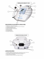
1
CAUTION
This device is not designed to be connected with any electrical equipment unless manufactured and approved by Rich-Mar.
NOTE: This includes whirpools and carbon electrodes NOT manufactured by Rich-Mar.
CAUTION: When using carbon electrodes with any Rich-Mar stimulator, a moistened interface (cloth or
sponge) MUST be utilized between these electrodes and the patient to avoid skin irritation and/or electrical
burns.
3
THIS PAGE INTENTIONALLY LEFT BLANK
4
TABLE OF CONTENTS
Therasound 3 Series Warranty...........................................6
Ultrasound Indications for Treatment................................ 7
Ultrasound Contraindications & Warnings.........................7
Introduction.....................................................................8
Therasound 3 and Therasound EVO Operation.. .............8
User Interface and Front Panel Display....................... ................9
Combining Therasound 3 Units with Stimulation........................10
Ultrasound Calibration & Tuning Procedure.....................11
Trouble Shooting............................................................ 13
Therasound 3 Series Specifications..................................13
Changing the Voltage of the Therasound 3 Series..............14
Appendix A
Ultrasound Technical Information..........................................17
5
WARRANTY
Rich-Mar warrants that our units are free of defects in material and workmanship.
This warranty shall remain in effect for (3) three years from the date of original customer purchase.
If these Products fail to funtion during the three year warranty period due to a defect in material or workmanship,
Rich-Mar or the selling dealer will repair or replace the respective Product without charge within a period of Thrity (30) days
from the date on which the Product is returned to Rich-Mar.
All repairs to the Product must be performed by Richmar or a Richmar Authorized Service Center.
Any modifications or repairs performed by unarthorized centers or groups will void this warranty.
The warranty period for certain accessories is 90 days. These accessories consist of Lead Wires and Electrodes.
The warranty period for the Ultrasound Applicators is one year (12 months).
To participate in warranty coverage, the Product's warranty registration card (included with the Product) must be filled out
and returned to Rich-Mar by the original owner within ten (10) business days from the date of purchase.
RICHMAR SHALL RESERVE THE RIGHT TO REQUEST PROOF OF PURCHASE
FROM THE END-USER TO VALIDATE THE WARRANTY PERIOD
This Warranty Does Not Cover:
~ Replacement parts or labor furnished by anyone other than Rich-Mar, the selling dealer or a certified service technician.
~ Defects or damage caused by labor furnished by someone other than Rich-Mar, the selling dealer or a certified service
technician.
~ Any malfunction in the Product caused by product misuse, including, but not limited to, the failure to provide reasonable and
required maintenance or any use that is inconsistent with the Product's User's Manual.
RICH-MAR SHALL NOT BE LIABLE IN ANY EVENT FOR INCIDENTAL OR CONSEQUENTIAL DAMAGES
Some states do not allow the exclusion or limitation of incidental or consequential damages, so the above limitation or exclusion
may not apply to you.
To Obtain Service from Rich-Mar or the selling dealer under this warranty:
1. A written claim must be made within the warranty period to Rich-Mar or the selling dealer.
Written claims made to Rich-Mar should be sent to:
Rich-Mar, Inc.
4120 South Creek Road
Chattanooga, TN 37406
Telephone (423)648-7730 / FAX(423) 648-7735
and
2. The Product must be returned to Rich-Mar or the selling dealer by the owner.
This warranty gives you specific legal rights and you may also have other rights which vary from location to location.
Rich-Mar does not authorize any person or representative to create for it any other obligation or liability in connection
with the sale of the Product.
Any representative or agreement not contained in the warranty shall be void and of no effect.
THE FOREGOING WARRANTY IS IN LIEU OF ALL OTHER WARRANTIES, EXPRESSED OR IMPLIED,
INCLUDING ANY WARRANTY OR MERCHANT ABILITY OR FINESS FOR A PARTICULAR PURPOSE.
6
Ultrasound Indications for Treatment
(Therapeutic Ultrasound)
Rich-Mar Ultrasound devices are indicated to produce therapeutic deep heat for the following conditions:
1) Relief of pain.
2) Muscle spasms.
3) Joint contractures.
But not for the treatment of malignancies.
WARNING - Federal law restricts this device to sale by or on the order of a physician or any other practitioner licensed by the law of the state in which said person practices.
Ultrasound Contraindications
Contraindications
Ultrasound should not be used in the following areas:
1) Near or over the heart.
2) Near or over the eyes.
3) On the head.
4) Near or over reproductive organs.
5) On the lower back during pregnancy or over the pregnant uterus.
6) Directly over the spinal column.
7) Over growing bone in children.
8) Where the skin suffers from any sensory impairment.
9) Over areas of malignancies.
10) In the area of visceral plexus and large autonomous ganglion.
11) Over the thoracic area if the patient is using a cardiac pacemaker.
12) Over a healing fracture.
13) Over ischemic tissues in individuals with vascular disease where the blood supply would be unable to
follow the increase in metabolic demand and tissue necrosis might result.
Precautions
Precautions should be taken when used:
1) Over anesthetized areas.
2) On patients with hemorrhagic diastheses.
3) Ultrasound treatment should not be performed over an area of the spinal cord following laminectomy (i.e.when major covering tissues have been removed).
Caution
1) Excessive doses of ultrasound may cause damage to tissue. Periosteal pain is an indication of excess
intensity and if it occurs, the power should be reduced; the transducer should be moved more rapidly over the
area being treated; or a lower pulsed duty cycle should be used.
2) If the soundhead has been operated unloaded for an extended period of time, the transducer will get hot. If
the soundhead is applied to the patient while the transducer is hot, a burn may result.
Warning
Do not operate the soundhead in an unloaded condition. It is possible that unrepairable damage may occur to
the transducer in an unloaded state.
7
Changing the Voltage from 115V to 230V
WARNING: RISK OF ELECTRICAL SHOCK.
Unplug unit prior to changing the voltage from 115 to 230.
1. After unplugging the unit, open
the outlet cover with a flathead
screwdriver by inserting it into the
notch as shown above.
2. Once the outlet cover is open,
insert the flathead screwdriver into
the notch on the red voltage
converter as shown above.
3. Holding the regulator so that
115V is right-side up, remove the
1amp slow blow fuse from the right
side.
4. Rotate the regulator until 230V 5. SAVE THE CLIP AS IT IS NEEDED TO SWITCH BACK TO
is right-side up. Remove the clip
115V. After correct fuses are inserted into each side, insert the regulator
from the right-hand side and insert into the slot with 230V reading right-side up as shown above.
two .5amp slow-blow fuses, one
on each side.
6. Finally, close the outlet cover, ensuring that the
desired voltage appears through the window in the
outlet cover. Also be sure to use an adapter for
the AC plug to suit local wall outlets in use.
115V to 230V Quick Check
, Take out 1amp slow blow fuse and remove clip on
back of 230V side.
, SAVE CLIP
, Insert two .5 amp slow blow fuses.
, Insert regulator with 230V appearing through the
window in outlet cover.
14
Changing the Voltage from 230V to 115V
WARNING: RISK OF ELECTRICAL SHOCK.
Unplug unit prior to changing the voltage from 230 to 115.
1. After unplugging the unit, open
the outlet cover with a flathead
screwdriver by inserting it into the
notch as shown above.
4. Hold the regulator so that
230V is right-side up. Insert the
clip into the right-hand side of the
regulator.
2. Once the outlet cover is open,
insert the flathead screwdriver into
the notch on the red voltage
converter as shown above.
3. Remove the two .5 amp slow
blow fuses from the voltage
regulator.
5. Rotate the regulator so that 115V is right-side up and insert one 1
amp slow blow fuse into the right side. Insert the regulator into the slot
in the unit with 115V reading right-side up.
6. Close the outlet cover, ensuring that 115V appears through the
window in the outlet cover. Also be sure to use an adapter for the
AC plug to suit local wall outlets in use.
230V to 115V Quick Check
Take out the two .5 amp slow blow fuses.
INSERT THE CLIP INTO THE RIGHT HAND
SIDE OF THE 230V REGULATOR
, Insert one 1 amp slow blow fuse.
, Insert regulator with 115V appearing through the
window in outlet cover.
15
THIS PAGE INTENTIONALLY LEFT BLANK
16
APPENDIX A
ULTRASOUND TECHNICAL INFORMATION
17
Ultrasound Technical
Information
Applicator Type:
The ultrasonic radiation fields produced by Rich-Mar
therapeutic ultrasound transducers are of the plane
wave type and are essentially cylindrical in shape. This
type of applicator is referred to as a collimating
applicator.
Applicator Label:
Each Rich-Mar applicator is labeled to provide the user
with information on its applicable parameters. The
following abbreviations are used on the label.
Near Field Distribution
Beyond this point, the beam has a more uniform intensity
and is called the “far field”. Below is shown the far field
distribution at 16cm from the transducer face.
Gen: The Rich-Mar ultrasonic generator
for which the applicator is intended.
f: The operating frequency in MHz for
the applicator.
Area: The effective radiating area of the
applicator in square centimeters.
BNR: The Beam Nonuniformity Ratio.
Type: Coll-means collimating applicator.
Near Field/ Far Field:
If measurements are made of the sound intensity along
the central axis of the beam produced by the applicator, the intensity distribution shows maxima and minima
near the applicator and then a gradual decline beyond
the last maximum intensity.
The “interference” or “near field” is the area in the
ultrasound beam extending from the applicator surface
to the location of the most distant intensity maximum.
In this area, maxima and minima of intensity are
located close to each other. This is the area in which
most therapeutic application occurs. This is shown in
the following figure measured 0.5cm from the transducer face.
Far Field Distribution
The preceding descriptions apply for radiation emitted
into the equivalent of an infinite medium of distilled,
degassed water at 30°C and with line voltage variations
in the range of +/-10% of the rated value
Transducer Parameters and Tolerances:
10cm² / 5cm² /Hammer (5cm² & 2cm²) Applicators
The Rich-Mar ultrasound units operate at frequencies of
either 1MHz or 3MHz +/- 10%. The effective radiating
areas (ERA) of the transducers are ten, five, or
two square centimeters, depending upon the size of
the transducer being used. The tolerance for the ERA
is +/-25% on the 2 and 5 square centimeter transducers. The tolerance for the 10 square centimeter
transducers is +0. -25%. The Beam-NonuniformityRatio (BNR) of any Rich-Mar transducer is 5.5:1 or
less.
18
Transducer Parameters and Tolerances:
Autosound Applicator
The Rich-Mar ultrasound units operate at frequencies
of either 1MHz or 3MHz +/- 10%. The effective
The error in indication of radiated power in intensity
radiating areas (ERA) of the transducers are ten, five,
for the pulsed mode does not exceed +/-14% allowing
three and a half (3.5), or two square centimeters,
for an allowable 6% error in the wattmeter, which
depending upon the size of the transducer being used.
equals +/-20%.
The tolerance for the ERA is +/-25% on the 2, 3.5 and 5
square centimeter transducers. The tolerance for the 10
Timer Accuracy
square centimeter transducers is +0. -25%.
The Food and Drug Administration requires that the
The Beam-Nonuniformity-Ratio (BNR) of any Rich-Mar treatment timer accuracy is to within 0.5 minutes for
transducer is 5.5:1 or less.
the preset duration of emission for settings less than
100% Mode
five minutes, to within 10% of the preset duration of
When operated in the 100% mode, the generator
emission for settings from five to ten minutes, and to
produces a non-interrupted sinusoidal waveform of one
within one minute of the preset duration of emission for
or three MHz. The peak power and average power
settings greater than ten minutes.
are therefore the same.
Ratio of Temporal Peak to Temporal Average
The error in indication of radiated power in intensity
(Rtpa):
for the continuous mode does not exceed +/- 14%
The ratios of temporal peak to temporal average
allowing for a 6% error in the wattmeter, which equals
intensities (Rtpa) will vary with the pulse rate of the
+/- 20%.
device. Depending upon the Rich-Mar model of
Pulsed Mode
therapeutic ultrasound in use, the duty cycle can be
When operated in the pulsed mode, the generator
chosen between 5% and 95% duty.
produces a square-wave burst of sinusoidal waveform
The Rtpa is calculated in the following manner:
of 1MHz or 3MHz of 2.5 milliseconds in duration.
Rtpa = (1/Duty):1
Depending upon the Rich-Mar model of therapeutic
Example 5% duty = .05 (min. duty, max. Rtpa)
ultrasound in use, the duty cycle can be chosen beRtpa = (1/.05):1
tween 5% and 95% duty. This then implies the repetiRtpa = 20:1
tion rate is selectable between 20 and 380 pulses per
Example 95% duty = .95 (max. pulsed duty, min. Rtpa)
second. (This is computed by taking the inverse of the
duty cycle 1/380 = .95, 1/20 = .05). The tolerance for
Rtpa = (1/.95):1
the pulsed mode is +/- 20%.
Rtpa = 1.05:1
See the following chart for second comparison on
See the following chart for %Duty cycle to Rtpa
%Duty cycle to pulses.
comparison.
% Duty Cycle
Pulses/Second
% Duty Cycle
(Indicated on front panel of device)
5
10
15
20
25
30
35
40
45
50
55
60
65
70
75
80
85
90
95
Rtpa
(Indicated on front panel of device)
20
40
60
80
100
120
140
160
180
200
220
240
260
280
300
320
340
360
380
19
5
10
15
20
25
30
35
40
45
50
55
60
65
70
75
80
20:1
10:1
8.33:1
5:1
4:1
3.33:1
2.86:1
2.5:1
2.22:1
2:1
1.82:1
1.66:1
1.54:1
1.43:1
1.33:1
1.25:1
85
90
95
1.18:1
1.11:1
1.05:1
The Rtpa tolerance does not exceed +/- 20%.
The temporal maximum intensity for each duty cycle
as well as the 100% modulation is whatever is indicated on the meter.
The temporal average intensity for each duty cycle will
be the meter indication multiplied by the percentage
duty cycle.
Temporal Average = (Duty) x (Meter Indication)
Example, 5 Watts, 35% Duty
Temporal Average = .35 x 5 Watts = 1.75 Watts
The Spatial Average Intensities for each of these
setting will be divided by the transducer’s Effective
Radiating Area (ERA)
Spatial Average = (Temporal Average)/(ERA)
Example, 5 Watts, 35% Duty, 5cm2 Transducer
Spatial Average = (1.75 Watts)/(5cm2 ) = 0.35 Watts/
cm2
The pulse width (On time) of all Rich-Mar therapeutic
ultrasound devices is 2.5 milliseconds (mS). The time
between pulses (Off time) in milliseconds is calculated
as follows:
Pulse width (On time) = 2.5mS
Off time = [2.5-2.5(%Duty cycle)]/(%Duty cycle)
Where %Duty cycle is represented as a decimal.
Please see the following example for computing the
Off time for a 10% Duty cycle:
Off time=[2.5-2.5(0.10)]/(0.10)=22.5 milliseconds.
Additional Technical Notes:
The peak power is the same in the pulsed modes as in
the 100% modulated mode.
Unless otherwise stated, all technical parameters are
accurate within +/- 20%.
When in the pulse modes the unit is still generating
therapeutic heat, although it is an amount reduced by a
factor directly related to the duty cycle. The pulse
rates are used to allow the practitioner to treat areas of
bony prominences without creating periosteal pain.
The line leakage is tested in both the forward and
reverse polarities to be less than 50 microamperes
exceeding all standards for medical devices in this
class.
20