1
PNC-3200
USER'S MANUAL
2
Cutting Using RML-1
Thank you very much for purchasing the PNC-3200.
•
To ensure correct and safe usage with a full understanding of
this product's performance, please be sure to read through this
manual completely and store it in a safe location.
•
Unauthorized copying or transferral, in whole or in part, of
this manual is prohibited.
•
The contents of this operation manual and the specifications of
this product are subject to change without notice.
•
The operation manual and the product have been prepared and
tested as much as possible. If you find any misprint or error,
please inform us.
Table of Contents
Introduction ....................................................................................................................................................2
Part 1 Basic Operations
1 About the Switch Panel .........................................................................................................................3
Making Setting Using the Liquid-crystal Display .......................................................................4
2 Setting the Origin (Home Position and Z0) ......................................................................................5
Setting the Home Position ............................................................................................................5
Setting the Z0 Position ..................................................................................................................6
Setting Z0 with the Z0 Position Sensor (Included withe the Unit) ..........................................7
3 Cutting Condition Setting .....................................................................................................................9
Manual Setting of Cutting Conditions .........................................................................................9
Cutting Condition Setting Examples ......................................................................................... 11
4 Setting the Z1 and Z2 Position ......................................................................................................... 12
5 Downloading Cutting Data ................................................................................................................ 13
6 Finishing ................................................................................................................................................. 14
Part 2 User's Reference
Cutting Area ................................................................................................................................................ 15
Coordinate System .................................................................................................................................... 16
Operating Each Function ......................................................................................................................... 17
Performing Repeat Cutting ........................................................................................................ 18
Changing the Feed Rate or Spindle Speed During Cutting ................................................. 19
Stopping the Cutting Process ................................................................................................... 20
Explanation of the Display Menus ........................................................................................................ 21
What to Do If... ............................................................................................................................................ 24
Error Messages .......................................................................................................................................... 25
Other Messages ......................................................................................................................................... 26
List of RML-1 Instructions ....................................................................................................................... 27
Device Control Instructions .................................................................................................................... 29
Display Menus Flowchart ........................................................................................................................ 31
Copyright © 1999,2000 ROLAND DG CORPORATION
1
Introduction
This document describes operation when performing cutting with the PNC-3200 using RML-1.
To perform cutting using RML-1, the command selection must be set to RML-1 when the PNC-3200 is switched on. For information on
how to select commands, see "User's Manual 1 -- Setup and Maintenance."
2
1
Part
1
Basic Operations
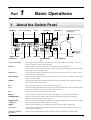
About the Switch Panel
HOME key
Liquid-crystal display
SPINDLE TEST
ON/OFF key
Z0 key
Z1 key
Z2 key
MENU key
Arrow keys
JOG Handle
VIEW key
ENTER/PAUSE
key
HANDLE FUNCTION
SELECT key
TOOL UP key
TOOL DOWN key
Liquid-crystal display
The settings and selection choices (or values) for the PNC-3200 are shown on this display. Error messages also appear here in the event of a problem.
Arrow keys
Pressing an arrow key causes the XY table to move in the corresponding direction.
The arrow keys are also used together with the liquid-crystal display to manipulate settings, select items,
display other choices, and change values.
TOOL UP key
This key makes the cutting tool (blade) move in a positive direction on the Z axis (i.e., upward). Movement is always at a constant speed.
TOOL DOWN key
This key makes the cutting tool move in a negative direction on the Z axis (i.e., downward). Movement is
always at a constant speed.
HOME key
This raises the tool (blade) to the highest point and moves the tool (blade) to the present home position
(the origin point on the X and Y axes).
Z0 key
This key moves the cutting tool to the current Z-axis origin point.
Z1 key
This key starts the spindle motor and moves the tool to the current tool-down position. When the spindle
switch is off, the spindle does not rotate and the tool does not move.
Z2 key
This key moves the tool to the current tool-up position.
MENU key
This key scrolls through the menu on the liquid-crystal display (i.e., it changes the panel display).
ENTER/PAUSE key
This key is used to confirm settings, values, and selections made with the liquid-crystal display.
When pressed during cutting, operation is paused.
SPINDLE TEST
ON/OFF key
This key is used to start and stop the spindle motor. To rotate, hold down the key for one second or longer.
When the spindle switch is off, the spindle does not rotate.
VIEW key
This key raises the cutting tool to its highest point and moves the XY table to the front left.
JOG handle
This is used for inching the XY table and cutting tool (in steps of 0.01 mm (0.00039 in)), and also to set
the speed of the spindle motor.
HANDLE FUNCTION
SELECT key
This key is used together with the liquid-crystal display to select the function of the JOG handle.
3
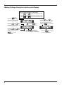
Making Settings Using the Liquid-crystal Display
When coordinate values are displayed:
Press the
Use the
and
keys to move along the X axis.
Use the
and
keys to move along the Y axis.
Use the
and
keys to move along the Z axis.
key to
keys
Use the
and
to move the blinking cursor (" ")
and select the execution item.
move the "*" and select the
function of the JOG handle.
Press the
and
keys
to move the blinking cursor (" ")
and select the setting item.
Press the
and
keys
to change the value (or selection
choice), and then press the
key to confirm.
4
Press the
key
to display the next menu.
The value (or selection choice)
enclosed in angled brackets
("< >") indicates the current setting.
Press the
Press the
key to execute.
key to toggle
the setting on or off.
2
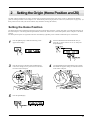
Setting the Origin (Home Position and Z0)
The PNC-3200 are suitable for use with a versatile range of workpiece shapes and a wide variety of tools, so determine the standard
points for cutting each time a new workpiece is set. Set the home position (origin point for X an Y axes) and Z0 (Z axis origin point). (If
these points can be set with your current software, they should be set using the software.)
Setting the Home Position
The home position is the point that becomes the origin point in the X and Y directions. Usually, this point is set at the front left corner of
the fixed workpiece. The setting method explained here, uses the left, bottom corner (nearest the operator) of the workpiece as the home
position.
The home position points are registered in the PNC-3200 memory right after power is turned on and before power is turned off.
1
Press the [MENU] key to make the following screen
appear on the display.
2
Press the HANDLE FUNCTION SELECT key to
move the "*" on the screen to "X" or "Y," then press
the [ENTER] key.
3
Press the arrow keys and the TOOL UP/DOWN keys
to move the cutting tool to a position close to the front
left corner of the workpiece.
4
Use the HANDLE FUNCTION SELECT key and the
JOG handle to align the cutting tool with the front left
corner of the workpiece.
Workpiece
5
Press the [ENTER] key.
Make sure that "< >" appears.
5
Setting the Z0 Position
The Z0 position is the point that becomes the origin point in the Z directions. Usually, this point is set at the surface of the fixed
workpiece. The following explains the method for setting the workpiece surface Z0 position. If "Z0_MEMORY" is off, then the Z0
position is set to the mechanically uppermost position immediately after the power is switched on.
1
Press the [MENU] key to make the following screen
appear on the display.
2
Press the HANDLE FUNCTION SELECT key to
move the "*" on the screen to "Z," then press the
[ENTER] key.
3
Press the [Z0] key to move the blinking cursor (" ") to
"Z0."
4
Press the arrow keys and the [TOOL UP/DOWN] keys
to move the cutting tool close to the surface of the
workpiece.
Workpiece
5
Rotate the JOG handle to align the tip of the cutting
tool with surface of the workpiece.
6
Press the [ENTER] key.
Make sure
that "< >" appears.
The following method can be used to
set the Z0 position even more precisely. This method is suitable for
cases where the position is marked
with an oil pen and later cut off.
Set Z0 as the position where the ink
was cut off.
First, make a mark on
the work surface with
a generally available
oil pen, etc.
Workpiece
6
Press the [SPINDLE TEST ON/
OFF] key to make the spindle
rotate. Place the tool in the
marked position, then lower the
tool until the ink is cut off. The
ink mark on the work surface
has a certain thickness, so only
the ink is removed.
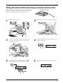
Setting Z0 with the Z0 Position Sensor (Included with the Unit)
The Z0 sensor included with the unit is used to set the Z0 point on the
surface of the workpiece. The Z0 sensor is placed on the location
which is to serve as the Z0 point, and the Z0 point is set.
Z0 position sensor
Z0
1
Install the Z0 position sensor.
2
Place the Z0 position sensor on top of the workpiece.
Z0 position
sensor jack
Z0 position sensor
3
Use the arrow keys and the tool up/down keys to move
to a position 2 to 3 mm (0.079 in. to 0.118 in.) above
surface of the Z0 sensor.
4
Press the [MENU] key to make the following screen
appear on the display.
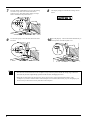
5
Press the [ ] key to move the blinking cursor (" ") to
"SENSOR OFF," then press the [ENTER] key.
6
The display changes to indicate the message shown
below.
7
7
Press the TOOL UP/DOWN keys to move the cutting
tool until its tip comes into contact with the Z0
position sensor. Movement of the cutting tool stops
when it touches the Z0 position sensor.
8
The display changes to indicate the message shown
below.
9
Use the tool-up key to raise the tool, then remove the
Z0 sensor.
10
Press the [Z0] key. The tool descends automatically to
the Z0 position, and the Z0 point is set.
Remove
• The Z0 sensor removed from above the workpiece in step 9 must be placed outside the cutting range. Otherwise
the cable may become caught during operation of the XY table, damaging the sensor.
• When the tool descends to the Z0 position in step 10, the tool may contact and scratch the surface of the
workpiece. If you don’t want the surface of the workpiece to be scratched, then before you press the [Z0] key, use
the arrow keys to move the tool away from above the workpiece.
8
3
Cutting Condition Setting
Before you begin the actual cutting process, the cutting conditions such as the revolution speed of the spindle motor and the feeding
speed of each axis must be designated according to the quality of the workpiece and the type of tool used. There are several deciding
factors to be taken into account when designating the cutting conditions.
The quality of the workpiece
The cutting method
The type of tool used
The cutting shape
The diameter of the tool used
Designate the cutting conditions in consideration of the above factors by performing the following three PNC-3200 setting operations.
1. The spindle motor revolution speed (tool revolution speed)
2. The feeding speed (tool moving speed)
3. The cutting-in amount (depth of one cutting operation)
Note : When settings have been made with both the software and the PNC-3200, the last settings made have
priority.
In this manual, these three conditions are called the cutting conditions. The characteristics and points to consider for each of these
conditions are as follows.
Item
Characteristics/Points to Consider
Spindle motor revolution
The bigger this number, the faster the cutting speed. However, if this number is too large, the work
surface may melt or burn due to excessive friction. Conversely, if this number is made smaller, the time
taken for cutting becomes too longer. Generally speaking, the entire cutting speed is determined by the
cutting edge speed, so the smaller the tool diameter, the higher the spindle revolution speed required.
(When performing engraving without rotating the cutting tool, set "REVOLUTION" to "OFF.")
Revolution speed : 3000—8000 rpm
speed
Feeding speed
Cutting-in amount
When the feeding speed is high, processing becomes rough and flash marks tend to remain on the cut
surface. On the other hand, when the feeding speed is slow, processing takes more time. Be careful
because a slower feeding speed does not always result in improved finishing.
When the cutting-in amount is deeper, the cutting speed increases, but the cutting-in amount is limited
by the quality of the workpiece. In cases where the required depth can not be cut at once, repeat cutting
several times to depth that does not breach the limit.
Manual Setting of Cutting Conditions
The cutting conditions can be set manually according to the method described below.
If the cutting conditions can be set with your current software, this is a faster and more efficient method than manual setting. It makes no
difference when you come to construct a program. The following method is appropriate for making delicate halfway adjustments to
conditions previously set using software, etc.
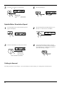
Feeding Speed
1
Press the [MENU] key to make the following screen
appear on the display.
2
Press the [ ] or [ ] key to move the blinking cursor
(" ") to "XY-SPEED."
To set the lowering speed of the head, move the
blinking cursor (" ") to "Z-SPEED."
9
3
Press the [ ] or [ ] key to set the feed rate.
4
Press the [ENTER] key.
Make sure that
"< >" appears.
Setting range
X- and Y-axis : 0 to 60 mm/sec
Z-axis
: 0 to 30 mm/sec
Spindle Motor Revolution Speed
1
Press the [MENU] key to make the following screen
appear on the display.
2
Press the HANDLE FUNCTION SELECT key to
move the "*" on the screen to "??00 RPM."
3
Rotate the JOG handle to set the speed of rotation.
4
To store the speed setting in memory, press the
[ENTER] key. The stored speed does not disappear
even when the power is turned off, but remains in
effect until the setting is changed.
Setting range:
3,000 to 8,000 rpm
RPM : Revolutions Per Minute
Cutting-in Amount
The cutting-in amount is set by setting Z1. For more information on the Z1 setting, see "4 Setting the Z1 and Z2 Position."
10
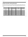
Cutting Condition Setting Examples
The chart below contains reference examples of the appropriate cutting conditions for several types of workpiece material. In the case
that the conditions are input using software or when constructing your own programs, set the cutting conditions with reference to the
chart. However, because conditions differ depending on tool sharpness and workpiece hardness, cutting performance may not always be
optimal when adhering to the conditions specified below. In such a case, delicate adjustment should be performed at the time of actual
cutting.
Workpiece
Spindle revolution
Cutting-in amount
Feeding speed
speed [RPM]
[mm]
[mm/sec.]
ZUS-600
8000
2.5
14
Chemical wood
ZUS-600
8000
0.6
14
Acrylic resin
ZUS-600
8000
0.3
14
ABS plastic
ZUS-600
8000
0.7
14
Aluminum
ZUS-600
8000
0.1
14
Brass
ZUS-600
8000
0.1
14
Modeling wax
Tool
(option)
11
4
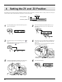
Setting the Z1 and Z2 Position
The cutting tool up position (Z2 point) and down position (Z1 point) are normally set with the software. If they cannot be set with your
current software then set them manually using the keys on the switch panel.
Tool
Tool up position
Z2
Z0
Tool down position Z1
Workpiece
1
Press the [MENU] key to make the following screen
appear on the display.
2
Press the HANDLE FUNCTION SELECT key to
move the "*" on the screen to "Z," then press the
[ENTER] key.
3
Press the [Z1] key to move the blinking cursor (" ") to
"Z1."
When setting the Z2 point, press the [Z2] key to move
the blinking cursor (" ") to "Z2."
4
Press the arrow keys and the TOOL UP/DOWN keys
to move the cutting tool close to the point where Z1
will be set.
When setting Z1, move the cutting tool to a position
away from the loaded workpiece.
Workpiece
5
Rotate the JOG handle to gradually move the cutting
tool to the height where the Z1 point is to be set.
6
Press the [ENTER] key.
Make sure
that "< >" appears.
12
5
Downloading Cutting Data
Do not operate beyond capacity or
subject the tool to undue force.
The tool may break or fly off in a random
direction. If and attempt is made by mistake
to perform cutting beyond capacity,
immediately switch off the spindle switch.
Do not insert the fingers between
the XY table and base or between
the head and Z cover.
Doing so may result in injury.
Do not insert the fingers between
the XY table and base or between
the head and Z cover.
The fingers may be pinched, resulting in
injury.
Base
XY Table
To keep cutting waste from being scattered, we recommend using a commercially available vacuum cleaner to take up
cutting waste during cutting. When attaching a vacuum cleaner to the PNC-3200, use a brush adapter for chip cleaning
(ZAD-10/ZAD-20), sold separately.
Data is sent from the computer (the program), and the PNC-3200 performs cutting.
The included 2.5D DRIVER is used to perform output from the program.
The 2.5D DRIVER can be found on the included CD-ROM. For information on how to install it, take a look at "PNC-3200 Setup &
Maintenance."
13
6
Finishing
Do not touch the tip of the blade
with your fingers.
Do not touch the tool immediately
after cutting operating stops.
Doing so may result in injury.
The tool may have become hot due to
friction heat and may cause burns if
touched.
When mounting or removing a tool,
first switch off the spindle switch.
Please use a vacuum cleaner to
remove cutting dust.
Do not use any blower like airbrush.
Doing so may result in injury.
Otherwise, dust spread in the air may harm
your health or damage this machine.
After cutting has been finished, detach the tool, remove the material, and clean away chips.
1
Press the [MENU] key to make the following screen
appear on the display.
2
Press the [VIEW] key for at least 0.5 seconds.
3
Turn off the spindle switch on the front of the unit.
4
Detach the tool.
LED Flashing
22 mm
(0.87 in.)
30 mm
(1.18 in.)
5
14
Remove the material.
6
Use a commercially available vacuum cleaner to take
up cutting waste.
Part
2
User's Reference
Cutting Area
The maximum cutting area of the PNC-3200 is 250 mm x 150 mm x 150 mm (9-13/16 x 5-7/8 x 5-7/8 in). When converted to coordinate values (step size: 1/100 mm (0.00039 in)), (x, y, z) = (25,000, 15,000, 15,000).
The actual available cutting area is subject to restrictions according to the length of the attached tool, the X table position at which the
workpiece is fixed, and the vice height (in the case that the vice is used); and in some cases it may be larger than the maximum operating
area.
150 mm (5-7/8 in.)
250 mm
(9-13/16 in.)
150 mm (5-7/8 in.)
15
Coordinate System
The PNC-3200 employs three separate coordinate systems (described below) according to the application or purpose of use.
Machine Coordinate
Under the machine coordinate system, the coordinates are determined
mechanically against the PNC-3200. This system forms the basis of
the "work coordinates" and "user coordinates" which are explained
later. The point to which the XY table and head move when the power
is turned ON is the origin of the machine coordinate system (x, y,
z)=(0, 0, 0). (The origin is fixed.)
The machine coordinate system basic unit is fixed as one step = 1/100
mm (0.00039 in).
The origin
of the machine
coordinates
Z
Y
X
Work Coordinate
The origin of the machine coordinate system is fixed, but there is a
coordinate system in which the origin can be moved relative to the
machine coordinate system. This system is called the work coordinate
system.
In the work coordinate system, the home position is the XY origin and
Z0 is the Z axis origin. The origin of the work coordinates can be set
by setting the home position (the XY axis origin) and Z0 (the Z axis
origin).
The origin of the work coordinates is the standard point for cutting
against the attached workpiece.
The work coordinate system basic unit is fixed as one step = 1/100
mm (0.00039 in).
User Coordinate
The origin
of the work
coordinates
Z
Y
X
* If you are using application software, there is no need to worry about the
user coordinate system. You can ignore it completely.
Under the machine coordinate system and the work coordinate system, the unit value is fixed. In contrast, the user coordinate
system allows the user to set the unit value freely. (However, the unit value can be set only for the XY axis. The Z axis unit
value cannot be set.)
The user coordinate system unit is determined by replacing (converting) the work coordinate system unit with the user coordinate
system unit. Also, the user can set the cutting data output to the position of the basic point of the workpiece on the XY axis. This
operation is called scaling. It can be performed with the use instructions.
If scaling is not performed, the user coordinate system unit and the work coordinate system unit are equivalent.
16
Operating Each Function
Making Settings with the Liquid-crystal Display
When coordinate values are displayed:
Press the
Use the
and
keys to move along the X axis.
Use the
and
keys to move along the Y axis.
Use the
and
keys to move along the Z axis.
key to
keys
Use the
and
to move the blinking cursor (" ")
and select the execution item.
move the "*" and select the
function of the JOG handle.
Press the
and
keys
to move the blinking cursor (" ")
and select the setting item.
Press the
and
keys
to change the value (or selection
choice), and then press the
key to confirm.
Press the
key
to display the next menu.
Press the
The value (or selection choice)
enclosed in angled brackets
("< >") indicates the current setting.
Press the
key to execute.
key to toggle
the setting on or off.
Changing to Other-language Messages on the Liquid-crystal Display
1
Switch on the power while holding down the [MENU]
key.
While pressing
the MENU key
2
Press the [ ] key to move the blinking cursor (" ") to
"
" and then press the [ENTER] key.
Turn the power on
+
3
Messages on the display now appear in Japanese.
* To return the display to English-language messages,
carry out Step 1 again. When the language-selection
menu appears (similar to the one in Step 1, but in
Japanese), move the cursor to "ENGLISH" and press
the [ENTER] key.
17
Performing Repeat Cutting
The data buffer is the place where data received from the computer is stored temporarily. (The data in the data buffer can be erased by
switching off the power or executing the "BUFFER-CLEAR".)
Executing the "REPEAT" calls up the cutting data stored in the PNC-3200's data buffer and executes the replotting procedure.
When replotting is executed, the entire data content of the data buffer is called up. When you perform replotting, clear the data from the
data buffer before sending the cutting for replotting from the computer.
1
Press the [MENU] key to make the following screen
appear on the display.
2
Press the [ ] key to move the blinking cursor (" ") to
"BUFFER CLEAR," then hold down the [ENTER]
key for at least 0.5 sec.
* The "BUFFER CLEAR"
text flashes.
3
Install the tool (blade) and load the material. Use the
software to send the cutting data.
4
After cutting has finished, remove the cut material and
load a new piece. Set the origin point if necessary.
5
Press the [MENU] key to make the following screen
appear on the display.
6
Press the [ ] key to move the blinking cursor (" ") to
"REPEAT," and then press the [ENTER] key.
18
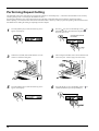
Changing the Feed Rate or Spindle Speed During Cutting
The feed rate and spindle rotating speed set by the software can be changed while cutting is in progress.
Changing the Feed Rate
This is done by first pausing the PNC-3200 during cutting, then changing the feed rate. However, if the computer subsequently sends a
command to change the feed rate, the setting will change as specified by the new command. When set by software or set directly on the
PNC-3200, the setting made last takes precedence.
1
Press the [ENTER/PAUSE] key while cutting is in
progress. One cutting step is performed, after which
operation stops. The display changes to show the
following message.
2
Press the [MENU] key to make the following screen
appear on the display.
3
Press the [ ] or [ ] key to move the blinking cursor
(" ") to "XY-SPEED."
To set the lowering speed of the head, move the
blinking cursor (" ") to "Z-SPEED."
4
Press the [ ] or [ ] key to set the feed rate.
Setting range
X- and Y-axis : 0 to 60 mm/sec
Z-axis
: 0 to 30 mm/sec
5
Press the [ENTER] key.
Make sure
that "< >" appears.
Canceling the Paused State to Resume Cutting
After changing the feed rate, cancel the paused state. Cutting then resumes at the new feed rate.
1
Press the [MENU] key to make the following screen
appear on the display.
2
Press the [ ] key to move the blinking cursor (" ") to
"CONTINUE," and then press the [ENTER] key.
19
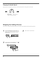
Changing the Spindle Speed
Spindle speed can be changed at any time. There is no need to pause operation. Use the jog dial to vary the speed.
LOW
HIGH
3,000 rpm
Setting range:
8,000 rpm
3,000 to 8,000 rpm
* RPM : Revolutions Per Minute
Stopping the Cutting Process
In the case that you begin cutting and then find that you have sent the wrong cutting data, perform the following operation.
1
Press the [ENTER/PAUSE] key while cutting is in
progress. One cutting step is performed, after which
operation stops. The display changes to show the
following message.
3
Press the [ ] key to move the blinking cursor (" ") to
"STOP," and then press the [ENTER] key.
20
2
Use the software to stop data output.
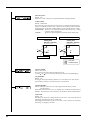
Explanation of the Display Menus
This shows the current position of the tool (in coordinates) and the spindle speed.
The coordinate values indicate the home position as the origin point on the X and Y
axes, and the Z0 point as the origin point on the Z axis. "RPM" is an abbreviations
for "revolutions per minute."
It is possible to move from this menu to submenus for setting the X- and Y-axis
origin point (home position), the Z-axis origin point (Z0), the tool-up position (Z2),
the tool down position (Z1), and the spindle speed.
This sets the X- and Y-axis origin point (home position). Use the arrow keys to
move the tool to the desired location for the home position, and press the [ENTER]
key.
For details, see "Setting the Home Position".
This sets the Z-axis origin point (Z0), tool-up position (Z2), and tool down position
(Z1). Move the blinking cursor (" ") on the display to "Z0," "Z1," or "Z2," align the
tip of the tool to the height to be set, then press the [ENTER] key.
For details, see "Setting the Z0 Position" or "4 Setting the Z1 and Z2".
This sets the spindle speed. Turn the jog handle to set the desired speed.
For details, see "Manual Setting of Cutting Conditions_Spindle Motor Revolution
Speed".
This shows the X/Y-axis feed rate and the Z-axis feed rate.
Move the blinking cursor (" ") on the display to "XY-SPEED" or "Z-SPEED" use
the [ ] or [ ] key to set the speed, and press the [ENTER] key.
For details, see "Manual Setting of Cutting Conditions_Feeding Speed".
"BUFFER-CLEAR"
This deletes any cutting data stored in the data buffer.
"REPEAT"
This loads cutting data that is stored in the data buffer and performs cutting. This
makes it possible to cut multiple copies of the same shape.
For details, see "Performing Repeat Cutting".
"SENSOR OFF"
This switches on a Z0 sensor connected to the PNC-3200. "SENSOR ON" is
displayed when the Z0 sensor is used to set the Z0 point.
For details, see "Setting Z0 with the Z0 Position Sensor".
"OTHERS"
This switches to the submenu for setting communication parameters when a serial
connection is used.
The submenus for "OTHERS"
are described on the following
page.
21
"REVOLUTION"
Default : ON
When set to "OFF," cutting can be performed without rotating the spindle.
"OVER_AREA"
Default : CONTINUE
This selects the action when the tool returns from a coordinate outside the cutting
range to a coordinate inside the range. (The tool cannot actually be moved outside
the cutting range, but the PNC-3200's internal processing handles this as if it had.)
"CONTINUE": Operation is not paused upon return to the cutting range. Cutting
continues without interruption.
"PAUSE"
: Operation is paused when the tool returns to the cutting range.
"CONTINUE"
1
"PAUSE"
Cutting Area
(250 mm x 150 mm)
Cutting Area
(250 mm x 150 mm)
(9-13/16 x 5-7/8 in.)
(9-13/16 x 5-7/8 in.)
2
Operation continues
1
2
Operation is paused
: Tool path
: Coodinate point
"MOVE_SPEED"
Default : 60 mm/sec
This sets the speed of movement with the tool raised.
Use the [ ] or [ ] key to set the movement speed, then press the [ENTER] key.
"Z0_MEMORY"
Default : ON
This toggles the Z0 point memory function on or off. When set to "ON," the Z0
point remains in memory even after the power is switched off.
"SENSE_HEIGHT"
Default : Thickness of the Z0 sensor when shipped from the factory (actual
measured value).
The thickness of the Z0 sensor can vary slightly due to conditions of temperature or
humidity. This allows the sensor thickness to be adjusted to match actual thickness.
"SMOOTH"
Default : ON
Smoothing is a function for cutting smooth arcs and circles. This selects the type of
smoothing. Smoothing can also be switched off.
When shipped from the factory, this is set to "ON." If arcs cannot be cut well using
this setting, try changing it to "OFF."
22
"COMMAND"
Default : AUTO
This selects the RML-1 command mode. When set to "AUTO," "MODE 1" or
"MODE 2" is determined automatically. If automatic determination is not made
correctly, find out what instruction system the application software (or driver
software) uses for data that is sent, and change this setting to "MODE1" or
"MODE2." To determine which mode your software is sending data in, refer to the
documentation for the software.
"I/O"
Default : AUTO
This sets the type of interface connected to the computer. When set to "AUTO," the
interface type (parallel or serial) is determined automatically. However, serial
communication parameters (baud rate, parity checking, stop bit, data bit, and
handshaking settings) are not determined and must be set.
"STOP"
Default : 1
This sets the number of stop bits when using a serial connection. Either 1 bit or 2
bits can be selected.
"DATA"
Default : 8
This sets the data bit length when using a serial connection. A length of either 7 bits
or 8 bits can be selected.
"PARITY"
Default : NONE
This makes the setting for parity checking when using a serial connection. The
available selections are no parity ("NONE"), even parity ("EVEN"), and odd parity
("ODD").
"BAUDRATE"
Default : 9600
This sets the baud rate when using a serial connection. The available selections are
9600 and 4800 bps.
"HANDSHAKE"
Default : HARDWIRE
This sets the handshaking mode when using a serial connection. Either hardwire
handshaking or Xon/Xoff control can be selected.
This shows the rotation time of the spindle. The spindle rotation time cannot be
returned to "0" (zero).
Refer to "Maintenance_Display of Spindle Rotation Time" in the separate "User's
Manual 1 -- Setup and Maintenance."
23
What to Do If...
When the PNC-3200 does not work
Is operation paused?
Cancel the paused state.
Is the power for the PNC-3200 switched on?
Make sure the PNC-3200 is powered up.
Is cutting data stored in the buffer?
No operation takes place if no cutting data is stored in the
buffer.
Switching off the power causes all cutting data stored in the
buffer to be deleted.
When the spindle does not rotate
Is the PNC-3200 Spindle switch OFF?
Turn the Spindle switch ON.
Is "REVOLUTION" set to "OFF?"
If "REVOLUTION" is set to "OFF," the spindle will cut without
rotating.
Refer to "Explanation od the Display Menus" and change the setting
for "REVOLUTION" to "ON."
Data cannot be sent
Do the PNC-3200's connection parameter
settings match the settings for the computer?
Refer to "6 Setting the Connection Parameters" in the separate
"User's Manual 1 -- Setup and Maintenance."
Has the connection cable come loose?
Make sure the connection cable is plugged in securely with no
looseness at either end.
Is the correct connection cable being used?
The type of connection cable varies according to the computer
being used. Also, some application software requires the use of
a special cable. Make sure the correct cable is being used.
Is the correct output device set for the application or driver software?
Refer to the manual for the application or driver software to set
the output device correctly.
If you're using the included "2.5D DRIVER," refer to "4
Setting Up the Program" in the separate "User's Manual 1 -Setup and Maintenance."
The power does not come on
Has the power cord come loose?
24
Make sure the power cord is plugged in securely with no
looseness at either end.
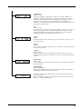
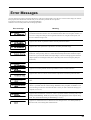
Error Messages
An error message will appear if incoming data has any of the errors listed in table. Since the error is shown in the display for informational purposes, the data transfer continues and you are allowed to perform the next operation.
To get the error message to go away, press the [ENTER] key.
Occurrence of an error may make correct cutting impossible.
Error message
Meaning
Appears if an instruction that the PNC-3200 cannot interpret is sent. This error is generated if
an instruction from the "mode2" set is sent when the unit has been set to recognize "mode1," or
viceversa. Change the setting for the recognized instruction set, using the control panel, and
this error should no longer occur.
Appears if the number of parameters differs from the permissible number.
Appears if the value specified for a parameter is out of the permissible range.
Appears if an output instruction is sent from the computer during execution of a previous output
instruction. More precisely, there is a certain amount of delay between the moment an output
instruction is given and the instant actual output begins. This error message appears if the new
output request arrives during this delay time. (The delay time can be set using the [ESC].M
instruction.)
Appears if a device control instruction that the PNC-3200 cannot interpret is sent.
Appears if an invalid parameter has been specified for a device control instruction.
Appears if the value for a device control instruction parameter exceeds the permissible limit.
Appears if the number of parameters for a device control instruction is more than that permissible.
Appears if a framing error, parity error, or overrun error occurs at the time of data reception.
(There is a problem with one of these settings: Baud Rate, Parity, Stop Bits, or Data Bits. The
protocol settings for the PNC-3200 must be made correctly in order to match the settings your
computer is set to use.)
Appears if the I/O buffer has overflowed. (There is a problem with the connecting cable, or the
settings for Handshaking. Make sure you are using a cable appropriate for the computer being
used. Also, check that the setting for Handshaking is correct.)
Appears if a communication error other than "Err10" through "Err16", one uninterpretable by
the PNC-3200, occurs during data communications.
25
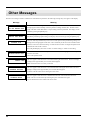
Other Messages
Besides error messages related to commands or communication parameters, the following messages may also appear on the display.
Message
CAN'T REPEAT
TOO BIG REPEAT DATA
Meaning
When the amount of cutting data exceeds the capacity of the PNC-3200's data buffer, this
message appear when an attempt is made to perform recutting with this data. The data cannot
all fit in the PNC-3200's data buffer, so repeat cutting cannot be performed. The display can be
cleared by pressing the [MENU] key.
CAN'T REPEAT
REPLOT DATA EMPTY
Hit "ENTER"
SPINDLE LOCK
This message appears if repeat cutting is attempted when the data buffer is empty. Send cutting
data before performing repeat cutting. The display can be cleared by pressing the [MENU] key.
The PNC-3200 stops automatically if an excessive load is placed on the spindle during cutting. The
message shown at right appears at this time. The overload may be due to excessive hardness of the
material, an excessive amount of cutting, or a feed rate that is too fast. Investigate the problem and
eliminate the cause of the overload.
Press the [ENTER] key, then select "CONT" to resume cutting or "STOP" to end cutting.
Pause ON
SPINDLE SWITCH OFF
CHECK Z0 POSITION
SENSOR JACK
When data has been sent from the computer to the PNC-3200, this message appears when the spindle
switch is set to OFF.
Turn on the spindle switch.
This error appears if the Z0 sensor is loose when entering the sensor mode. The error message
is displayed for approximately two seconds, then disappears.
Make sure the Z0 sensor is securely connected.
CAN'T TURN ON
Z0SENSOR NOTHING
This error appears if the Z0 sensor is not connected when entering the sensor mode. The error
message is displayed for approximately two seconds, then disappears.
Connection the Z0 sensor before entering the sense mode.
EMERGENCY STOP
Z0SENSOR ERROR
26
This error appears if the Z0 sensor is detached when the tool is moved while in the sensor
mode. The error can be cleared by switching the power off and back on again.
Do not detach the Z0 sensor while in the sensor mode.
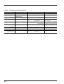
List of RML-1nstructions
* 1 : -(223-1)—+(223-1)
mode1
Instruction
@
Input Z1 & Z2
Format
Parameter
@ Z1, Z2
H
Range [Default]
Z1
Position on Z1
-12000—0 [0]
Z2
Position on Z2
0—+12000 [0]
H
Home
None
D
Draw
D x1, y1, x2, y2, ..... , xn, yn
xn, yn
Absolute coordinate
*1
M
Move
M x1, y1, x2, y2, ..... , xn, yn
xn, yn
Absolute coordinate
*1
I
Relative Draw
I x1, y1, x2, y2, ..... ,
xn, yn
Relative coordinate
*1
xn, yn
Relative coordinate
*1
xn, yn
R
Relative Move
R x1, y1, x2, y2, ..... ,
xn, yn
V
Velocity Z-axis
Vf
f
Feed rate for Z axis
0—30 [mm/sec] [2 [mm/sec]]
F
Velocity X,Y-axis
Ff
f
Feed rate for X and Y axis
0—60 [mm/sec] [2 [mm/sec]]
Z
XYZ-axis
Z x1, y1, z1, ..... , xn, yn, zn
xn, yn
XY coordinate
*1
Simultaneous Feed
Z x1, y1, z1, ..... , xn, yn, zn
zn
Z coordinate
*1
W
Dwell
Wt
t
Dwell time
0—32767 [msec] [2 [msec]]
^
Call mode2
^ [mode2] [parameter].....
[parameter] [;]
mode2
Instruction
DF Default
IN
Initialize
PA Plot Absolute
Format
Parameter
DF;
Range [Default]
None
IN;
None
PA x1, y1 (,x2, y2, ..... , xn, yn);
xn, yn
Absolute XY coordinate
*1
xn, yn
XY coordinate
*1
Relative XY coordinate
*1
xn, yn
XY coordinate
*1
s
Feed rate for X and Y axis
0—60 [mm/sec] [2 [mm/sec]]
PA;
PD Pen Down
PD x1, y1 (,x2, y2, ..... , xn, yn);
PR Plot Relative
PR x1, y1 (, x2, y2, ..... ,
PD;
xn, yn
xn, yn);
PR;
PU Pen Up
PU x1, y1 (,x2, y2, ..... , xn, yn);
PU;
VS Velocity select
VS s;
VS;
27
mode1, mode2 common instruction
Instruction
!DW Dwell
!MC Motor Control
Format
Parameter
Range [Default]
!DW t [terminator]
t
Dwell time
0—32767 [0]
!MC n [terminator]
n
Motor ON/OFF switching
-32768—32767 [motor ON]
!MC [terminator]
!NR Not Ready
!NR [terminator]
None
!PZ Set Z1&Z2
!PZ z1 (,z2) [terminator]
z1
Z1 coordinates
-12000—0 [0]
z2
Z2 coordinates
0—12000 [0]
!RC Revolution
!RC n [terminator]
n
Spindle motor
0—15
revolution speed
!VZ Velocity Select
[Value set by using panel keys]
!VZ s [terminator]
s
Feed rate (Z axis)
0—30 [mm/sec] [2 [mm/sec]]
Z-axis
!ZM Z-axis Move
!ZM z [terminator]
z
Z coordinate
-12000—0
!ZO Set Z0
!ZO z [terminator]
z
Z machine coordinate
-12000—0
!ZZ XYZ-axis
!ZZ x1, y1, z1, .....,
Simultaneous Feed
28
xn, yn
XY coordinate
*1
zn
Z coordinate
*1
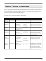
Device Control Instructions
The Device Control instructions determine how communication between the PNC-3200 and the computer will be handled using the RS232C interface; and also are employed when relaying to the computer the status of the PNC-3200. Some of them can be used to format
the output for RML-1 instructions.
A Device Control instruction is composed of three characters: ESC (1Bh), a ".", and an uppercase letter. There are also two types of
device control instructions: one carries parameters and the other does not.
Parameters can be omitted. Semicolons, " ; " are used as separators between parameters. A semicolon without parameters means that
parameters have been omitted. Device Control instructions with parameters require a terminator to indicate the conclusion of the
instruction. A colon " : " is used as the terminator, and it must not be omitted.
No terminator is necessary for Device Control instructions without parameters.
Instruction
Format
Handshake Instructions
ESC .B
[ESC].B
Output Remaining
Buffer Capacity
ESC .M
[ESC].M<P1>;<P2>;
Set Handshake
<P3>;<P4>;<P5>;
Output
<P6>:
Specifications (1)
ESC .N
Set Handshake
Output
Specifications (2)
ESC .H
Sets ENQ/ACK
Handshake Mode1
ESC .I
Set Xon/Xoff
Handshake and
ENQ/ACK
Handshake Mode2
ESC .@
Controls DTR
Parameter
Range
([ ] is default)
None
P1: Delay time
P2: Output trigger character
P3: Echo terminator
P4: Output terminator
P5: Output terminator
P6: Output initiator
[ESC].N<P1>;<P2>; P1: Intercharacter delay
<P3>; ••••• ;<P11>:
P2-P11
: Xoff character (for Xon/Xoff)
Immediate response character
(for ENQ/ACK)
[ESC].H<P1>;<P2>; P1: The number of bytes for
<P3>; •••••••• ;<P12>:
data block
P2: ENQ character
P3-P12
: ACK character (only when
<P2> is set)
[ESC].I<P1>;<P2>;
P1: Limit of the remaining
<P3> ; •••••••• ;<P12>: buffer capacity (for Xon/Xoff)
The number of data block bytes
(for ENQ/ACK (mode2))
P2: ENQ character
(for ENQ/ACK (mode2))
0 (for Xon/Xoff)
P3-P12
: Xon character(for Xon/Xoff)
ACK character
(for ENQ/ACK (mode2))
[ESC].@ P1;P2:
P1: Ignored
P2: DTR signal control
Explanation
Outputs the current remaining buffer capacity to the
computer.
0-32767 (msec) [0 (msec)]
[0 (Sets nothing)]
[0 (Sets nothing)]
[13 ([CR])]
[0 (Sets nothing)]
[0 (Sets nothing)]
0-32767 (msec) [0 (msec)]
[All 0 (Sets nothing)]
0-15358 (byte) [80 (byte)]
[0 (Sets nothing)]
[All 0 (Sets nothing)]
0-15358 (byte) [80 (byte)]
[0 (Sets nothing)]
Sets handshake output specifications.
Note: When you specify some values to <P4> and
<P5>, always set 0 to <P6>. When you specify
some value to <P6>, always set 0 to <P5>.
Sets an intercharacter delay, and also an Xoff
character for performing the Xon/Xoff handshake.
When receiving the ENQ character set by <P2>,
compares the value set by <P1> and the remaining
buffer capacity, and returns the ACK character to
the host computer when the remaining buffer
capacity is larger. The [ESC].H with no parameter
performs a dummy handshake.
Used for performing the Xon/Xoff handshake and
the ENQ/ACK handshake mode 2.
The [ESC].I instruction with no parameter performs
a dummy handshake. In a dummy handshake,
always returns the ACK character to the host
computer, regardless of the remaining buffer
capacity, when receiving the ENQ character.
[All 0 (Sets nothing)]
0-255
[1]
Controls the DTR signal (No. 20 pin of RS-232C).
An even number parameter (e.g. 0) always sets the
DTR signal to High without performing the
hardware handshake. An odd number parameter
(e.g. 1) performs the hardware handshake and
controls the DTR signal according to the remaining
buffer capacity.
29
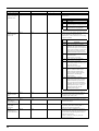
Instruction
Format
Status Instructions
ESC .O
[ESC].O
Outputs the Status
of Buffer, Pause
ESC .E
Output RS-232C
Error Code
[ESC].E
Parameter
None
Range
([ ] is default)
Explanation
Outputs the status codes of PNC-3200 shown in
the table below.
Code
Meaning
0
Data remaining in buffer.
8
Buffer empty.
16
Data remaining in buffer. PNC-3200
being paused (Pause On being displayed).
24
Buffer empty. PNC-3200 being
paused (Pause On being displayed).
None
Outputs an error code related to RS-232C interface
(see the table below), and clears the error
simultaneously. At the same time, the error being
displayed is canceled.
Error
Possible cause
code
and action
0
No I/O errors
10
Cause: after execution of an output
command, other output instructions are
sent before the output was not completed.
Action: let the computer to read the PNC3200 output by the output instruction
and then send another output instruction.
11
Cause: an error occurs in a device
control instruction.
Action: correct your program.
13
Cause: parameters are overflowing.
Action: correct your program.
14
Cause: the number of the parameters set
is more than specified or a colon ':' was
not used to terminate.
Action: correct your program.
15
Cause: framing error, parity error or overrun error at the time of data receipt .
Action: match the communication
protocols of both computer and PNC3200 (baud rate, data bit length,
stop bit length).
16
Cause: the I/O buffer overflows.
Action: This error does not occur when
hardware handshake is performed, but
may occur when software handshake is
performed. If this error occurs, check the
remaining buffer capacity of the PNC3200 and send less data than the
remaining buffer capacity.
ESC .L
Output I/O buffer
size
Abort Instructions
ESC .J
Abort Device
Control Instruction
ESC .K
Abort RML-1
Instruction
ESC .R
Initialize Device
Control Instruction
30
[ESC].L
None
PNC-3200 outputs the size of the I/O buffer to
the computer when receiving this instruction.
It usually outputs 1024 (bytes).
[ESC].J
None
Aborts both the currently executed device control
instruction and output.
[ESC].K
None
[ESC].R
None
Continues to execute the RML-1 instruction
in operation, aborts other incoming RML-1
instructions and clears the data buffer.
Initializes all settings established by the device
control instructions. Execution of [ESC].R brings
the same states as the following device control
instructions are executed.
[ESC].J, [ESC].M:, [ESC].N:, [ESC].H:,
[ESC].I: and [ESC].@:
Display Menus Flowchart
Switch on the power while holding
down the [MENU] key
POWER ON
Use
or
to select
the language used for the display,
then press
Use
or
to select
the "RML-1", then press
to move the
Use
"*" to "X" or "Y," then press
Use
to move the
"*" to "Z," then press
Use
to move the
"*" to "??00RPM," then press
Use
or
,
Use
or
to move the blinking cursor.
to move
the blinking cursor to "OTHERS,"
then press
For I/O, select "PARALLEL"
then press
For I/O, select "SERIAL" or
"AUTO" then press
31
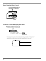
Menu Flowchart When Paused
Press the [ENTER/PAUSE] key
while cutting is in progress.
Flowchart from the Emergency-stop Menu
Emergency stop due to excessive load
on the spindle motor during cutting
Use
or
to select "CONT" or "STOP", then press
* Resuming operation is possible, but not recommended. Cutting precision after resuming operation is
not guaranteed. When operation is resumed, the machine coordinates for the X, Y, and Z axes are
detected again, and operation starts from the portion where the emergency stop occurred.
Position where cutting resumes
Position where cutting stopped
32
R4-000229