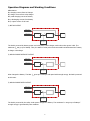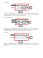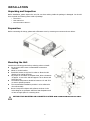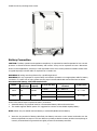
1
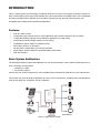
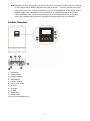
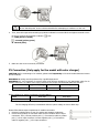
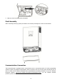
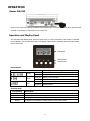
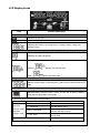
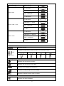
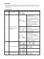
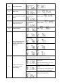
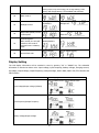
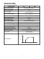
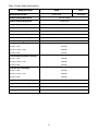
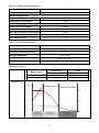
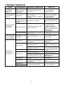
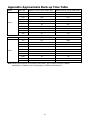
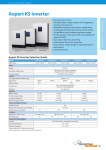
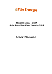
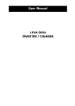
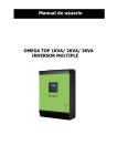
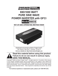
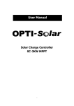
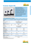
User Manual 4KVA/ 5KVA INVERTER / CHARGER CONTENTS ABOUT THIS MANUAL ..................................................................................................................................... 1 Purpose ............................................................................................................................................................ 1 Scope ............................................................................................................................................................... 1 SAFETY INSTRUCTIONS.................................................................................................................................. 1 INTRODUCTION ............................................................................................................................................... 2 Features ........................................................................................................................................................... 2 Basic System Architecture ............................................................................................................................... 2 Product Overview ............................................................................................................................................. 3 Operation Diagrams and work conditions ........................................................................................................ 4 INSTALLATION ................................................................................................................................................... 6 Unpacking and Inspection................................................................................................................................ 6 Preparation ...................................................................................................................................................... 6 Mounting the Unit ............................................................................................................................................. 6 Battery Connection .......................................................................................................................................... 7 AC Input/Output Connection ............................................................................................................................ 8 PV Connection (Only apply for the model with solar charger) ......................................................................... 9 Final Assembly ............................................................................................................................................... 10 OPERATION ..................................................................................................................................................... 11 Power ON/OFF .............................................................................................................................................. 11 Operation and Display Panel ......................................................................................................................... 11 LCD Display Icons ......................................................................................................................................... 12 LCD Setting .................................................................................................................................................... 14 Display Setting ............................................................................................................................................... 16 Operating Mode Description .......................................................................................................................... 19 Fault Reference Code .................................................................................................................................... 20 Warning Indicator ........................................................................................................................................... 20 SPECIFICATIONS ........................................................................................................................................... 21 Table 1 Line Mode Specifications ................................................................................................................... 21 Table 2 Invert Mode Specifications ................................................................................................................ 22 Table 3 Charge Mode Specifications .............................................................................................................. 23 Table 4 General Specifications ....................................................................................................................... 23 Charging Controls ........................................................................................................................................... 23 TROUBLE SHOOTING ..................................................................................................................................... 24 Appendix: Approximate Back-up Time Table ........................................................................................... 25 ABOUT THIS MANUAL Purpose This manual describes the assembly, installation, operation and troubleshooting of this unit. Please read this manual carefully before installations and operations. Keep this manual for future reference. Scope This manual provides safety and installation guidelines as well as information on tools and wiring. SAFETY INSTRUCTIONS WARNING: This chapter contains important safety and operating instructions. Read and keep this manual for future reference. 1. Before using the unit, read all instructions and cautionary markings on the unit, the batteries and all appropriate sections of this manual. 2. CAUTION --To reduce risk of injury, charge only deep-cycle lead acid type rechargeable batteries. Other types of batteries may burst, causing personal injury and damage. 3. Do not disassemble the unit. Take it to a qualified service center when service or repair is required. Incorrect re-assembly may result in a risk of electric shock or fire. 4. To reduce risk of electric shock, disconnect all wirings before attempting any maintenance or cleaning. Turning off the unit will not reduce this risk. 5. CAUTION – Only qualified personnel can install this device with battery. 6. NEVER charge a frozen battery. 7. For optimum operation of this inverter/charger, please follow required spec to select appropriate cable size. It’s very important to correctly operate this inverter/charger. 8. Be very cautious when working with metal tools on or around batteries. A potential risk exists to drop a tool to spark or short circuit batteries or other electrical parts and could cause an explosion. 9. Please strictly follow installation procedure when you want to disconnect AC or DC terminals. Please refer to INSTALLATION section of this manual for the details. 10. Fuses (4 pieces of 30A, 150VDC for 4KVA and 5pcs of that for 5KVA) are provided as over-current protection for the battery supply. 11. GROUNDING INSTRUCTIONS -This inverter/charger should be connected to a permanent grounded wiring system. Be sure to comply with local requirements and regulation to install this inverter. 12. NEVER cause AC output and DC input short circuited. Do NOT connect to the mains when DC input short circuits. 13. Warning!! Only qualified service persons are able to service this device. If errors still persist after following troubleshooting table, please send this inverter/charger back to local dealer or service center for maintenance. 1 INTRODUCTION This is a multi-function inverter/charger, combining functions of inverter, solar charger and battery charger to offer uninterruptible power support with portable size. Its comprehensive LCD display offers user-configurable and easy-accessible button operation such as battery charging current, AC/solar charger priority, and acceptable input voltage based on different applications. Features Pure sine wave inverter Configurable input voltage range for home appliances and personal computers via LCD setting Configurable battery charging current based on applications via LCD setting Configurable AC/Solar Charger priority via LCD setting Compatible to mains voltage or generator power Auto restart while AC is recovering Overload/ Over temperature/ short circuit protection Smart battery charger design for optimized battery performance Cold start function Basic System Architecture The following illustration shows basic application for this inverter/charger. It also includes following devices to have a complete running system: Generator or Utility. PV modules (option) Consult with your system integrator for other possible system architectures depending on your requirements. This inverter can power all kinds of appliances in home or office environment, including motor-type appliances such as tube light, fan, refrigerator and air conditioner. Figure 1 Hybrid Power System 2 Note: Appliances such as air conditioner are required at least 2~3 minutes to restart because it’s required to have enough time to balance refrigerant gas inside of circuits. If a power shortage occurs and recovers in a short time, it will cause damage to your connected appliances. To prevent this kind of damage, please check manufacturer of air conditioner if it’s equipped with time-delay function before installation. Otherwise, this inverter/charger will trig overload fault and cut off output to protect your appliance but sometimes it still causes internal damage to the air conditioner. Product Overview 1. LCD display 2. Status indicator 3. Charging indicator 4. Fault indicator 5. Function buttons 6. Power on/off switch 7. AC input 8. AC output 9. PV input 10. Battery input 11. Circuit breaker 12. RS-232 communication port 3 Operation Diagrams and Working Conditions Abbreviation: IUC, charging current from AC charger ISC, charger current from solar charger ICHG, total charging current of battery IDISC, discharging current from battery ILOAD, output current of AC load 1) BAT AC OUTPUT Utility Source Solar Source Solar Charger Isc IDISC DC/AC Inverter ILOAD AC Load Battery Bank The load is powered by battery power and solar power. Solar charger works when solar power is OK. The maximum ISC will go up to 50Amp. Then, the status of solar power and connected load will determine if battery is charge or discharge. 2) SOLAR CHARGE WITHOUT OUTPUT Utility Source Solar Source Solar Charger Isc DC/AC Inverter AC Load Battery Bank Solar charges the battery. The Max. ISC goes up to 50Amp if solar panel with enough energy. No load is powered at this state. 3) SOLAR CHARGE WITH OUTPUT Utility Source Solar Source Solar Charger Isc DC/AC Inverter ILOAD AC Load Battery Bank The load is powered by the utility. Solar power charges the battery. The maximum ISC will go up to 50Amp if enough energy is generated by solar modules. 4 4) AC CHARGE Utility Source Solar Source Iuc Solar Charger DC/AC Inverter ILOAD AC Load Battery Bank The battery is charged by the utility. The maximum IUC is 30Amp. The solar charger doesn’t work. When the power ON/OFF switch is turned “ON”, the device will generate output to the load. When the power ON/OFF switch is turned “OFF”, the device won’t generate output to the load. 5) AC & SOLAR CHARGE Utility Source Solar Source Solar Charger Isc Iuc DC/AC Inverter ILOAD AC Load Battery Bank The battery is charged by the utility and solar power at the same time. ICHG = IUC + ISC and the maximum ICHG is 50Amp. When the power ON/OFF switch is turned “ON’, the device will generate output to the load. If the power ON/OFF switch is turned “OFF”, the device won’t generate output to the load. 6) NO CHARGE Utility Source Solar Source DC/AC Inverter Solar Charger ILOAD AC Load Battery Bank When the power ON/OFF switch is turned “ON”, the device will generate output to the load. If the power ON/OFF switch is turned “OFF”, the device won’t generate output to the load. There is no charging current to the battery. 5 INSTALLATION Unpacking and Inspection Before installation, please inspect the unit. Be sure that nothing inside the package is damaged. You should have received the following items inside of package: The unit x 1 User manual x 1 Communication cable x 1 Preparation Before connecting all wirings, please take off bottom cover by removing two screws as shown below. Mounting the Unit Consider the following points before selecting where to install: Do not mount the inverter on flammable construction materials. Mount on a solid surface Install this inverter at eye level in order to allow the LCD display to be read at all times. For proper air circulation to dissipate heat, allow a clearance of approx. 10 cm to the side and approx. 50 cm above and below the unit. The ambient temperature should be between 0°C and 55°C to ensure optimal operation. The recommended installation position is to be adhered to the wall vertically. Be sure keep other objects and surfaces as shown in the below diagram to guarantee sufficient heat dissipation and to have enough space for removing wires. SUITABLE FOR MOUNTING ON CONCRETE OR OTHER NON-COMBUSTIBLE SURFACE ONLY. 6 Install the unit by screwing three screws. Battery Connection CAUTION: To safety operation and regulation compliance, it’s requested to install a separate DC over-current protector or disconnect device between battery and inverter. It may not be requested to have a disconnect device in some applications, however, it’s still requested to have over-current protection installed. Please refer to typical amperage in below table as required fuse or beaker size. WARNING! All wiring must be performed by a qualified personnel. WARNING! It's very important for system safety and efficient operation to use appropriate cable for battery connection. To reduce risk of injury, please use the proper recommended cable and terminal size as below. Recommended battery cable and terminal size: Model Typical Battery Amperage capacity 4KVA 67A 200AH 5KVA 84A 200AH 1~3 m one-way Ring Type for Cable Terminal 1*4AWG KST: RNBS22-6 2*8AWG KST: RNBS14-6 1*4AWG KST: RNBS22-6 2*8AWG KST: RNBS14-6 Torque value 2~ 3 Nm 2~ 3 Nm Please follow below steps to implement battery connection: 1. Assemble battery ring terminal based on recommended battery cable and terminal size. 2. This model supports 48VDC system. It’s suggested to connect at least 200Ah capacity battery. NOTE: Please only use sealed lead acid battery or sealed GEL/AGM lead-acid battery. 3. Insert the ring terminal of battery cable flatly into battery connector on the inverter and make sure the bolts are tightened to a torque of 2-3 Nm. Make sure polarity at both the battery and the inverter/charge is correctly connected and ring terminals are tightly screwed to the battery terminals. 7 WARNING: Shock Hazard Installation must be performed with care due to high battery voltage in series. CAUTION!! Do not place anything between the flat part of the inverter terminal and the ring terminal. Otherwise, overheating may occur. CAUTION!! Do not apply anti-oxidant substance on the terminals before terminals are connected tightly. CAUTION!! Before making the final DC connection or closing DC breaker/disconnector, be sure positive (+) must be connected to positive (+) and negative (-) must be connected to negative (-). AC Input/Output Connection CAUTION!! Before connecting to AC input power source, please install a separate AC breaker between inverter and AC input power source. This will ensure the inverter can be securely disconnected during maintenance and fully protected from over current of AC input. The recommended spec of AC breaker is 40A for 4KVA and 50A for 5KVA. CAUTION!! There are two terminal blocks with “IN” and “OUT” markings. Please do NOT mis-connect input and output connectors. WARNING! All wiring must be performed by a qualified personnel. WARNING! It's very important for system safety and efficient operation to use appropriate cable for AC input connection. To reduce risk of injury, please use the proper recommended cable size as below. Suggested cable requirement for AC wires Model AWG no. Torque 4KVA 10 AWG 1.4~1.6Nm 5KVA 8 AWG 1.4~1.6Nm Please follow below steps to implement AC input/output connection: 1. Before making AC input/output connection, be sure to open DC protector or disconnector first. 2. Remove insulation sleeve 10mm for six conductors. And shorten phase L and neutral conductor N 3 mm. 3. Insert AC input wires according to polarities indicated on terminal block and tighten the terminal screws. Be sure to connect PE protective conductor ( ) first. L→LINE (brown or black) →Ground (yellow-green) N→Neutral (blue) 8 WARNING: Be sure that AC power source is disconnected before attempting to hardwire it to the unit. 4. Then, insert AC output wires according to polarities indicated on terminal block and tighten terminal screws. Be sure to connect PE protective conductor ( L→LINE (brown or black) ) first. →Ground (yellow-green) N→Neutral (blue) 5. Make sure the wires are securely connected. PV Connection (Only apply for the model with solar charger) CAUTION: Before connecting to PV modules, please install separately a DC circuit breaker between inverter and PV modules. WARNING! All wiring must be performed by a qualified personnel. WARNING! It's very important for system safety and efficient operation to use appropriate cable for PV module connection. To reduce risk of injury, please use the proper recommended cable size as below. Model Typical Amperage Cable Size Torque 4KVA/5KVA 50A 8 AWG 1.4~1.6 Nm Please configure PV system as following recommendation: Model Best Vmp 4KVA/5KVA 60Vdc Vmp range 56V~72V Note: * Vmp: panel max power point voltage. The PV charging efficiency is maximized while PV system voltage is close to Best Vmp. Please follow below steps to implement PV module connection: 1. Remove insulation sleeve 10 mm for positive and negative conductors. 2. Check correct polarity of connection cable from PV modules and PV input connectors. Then, connect positive pole (+) of connection cable to positive pole (+) of PV input connector. Connect negative pole (-) of connection cable to negative pole (-) of PV input connector. 9 3. Make sure the wires are securely connected. Final Assembly After connecting all wirings, please put bottom cover back by screwing two screws as shown below. Communication Connection This inverter/charger is equipped with a communication port to communicate with a PC with corresponding software. Please use supplied communication cable to connect to RS-232 of this inverter and RS-232 port of the PC. Please access software download site to download the monitoring software in your PC. Software download website: www.power-software-download.com/watchpower.html. For the detailed software operation, please check user manual of software. 10 OPERATION Power ON/OFF Once the unit has been properly installed and the batteries are connected well, simply press On/Off switch (located on the button of the case) to turn on the unit. Operation and Display Panel The operation and display panel, shown in below chart, is on the front panel of the inverter. It includes three indicators, four function keys and a LCD display, indicating the operating status and input/output power information. LCD display LED indicators Function keys LED Indicator LED Indicator Green Green Red Messages Solid On Output is available in bypass mode Flashing Output is powered by battery in inverter mode Solid On Battery is fully charged Flashing Battery is charging. Solid On Fault mode Flashing Warning mode Function Keys Function Key Description ESC Exit setting mode UP To previous selection DOWN To next selection ENTER To confirm the selection in setting mode or enter setting mode 11 LCD Display Icons Icon Function description Input Source Information Indicates the AC input. Indicates the PV input Indicate input voltage, input frequency, PV voltage, battery voltage and charger current. Configuration Program and Fault Information Indicates the setting programs. Indicates the warning and fault codes. Warning: Fault: flashing with warning code. lighting with fault code Output Information Indicate output voltage, output frequency, load percent, load in VA and load in Watt. Battery Information Indicates battery level by 0-24%, 25-49%, 50-74% and 75-100% in battery mode and charging status in line mode. In AC mode, it will present battery charging status. Status Battery voltage <2V/cell Constant 2 ~ 2.083V/cell Current mode / Constant Voltage mode LCD Display 4 bars will flash in turns. Bottom bar will be on and the other three bars will flash in turns. Bottom two bars will be on and the other two bars will flash in turns. Bottom three bars will be on and the top 2.083 ~ 2.167V/cell > 2.167 V/cell bar will flash. Floating mode. Batteries are fully charged. 4 bars will be on. 12 In battery mode, it will present battery capacity. Load Percentage Battery Voltage LCD Display < 1.717V/cell 1.717V/cell ~ 1.8V/cell Load >50% 1.8 ~ 1.883V/cell > 1.883 V/cell < 1.817V/cell 1.817V/cell ~ 1.9V/cell 50%> Load > 20% 1.9 ~ 1.983V/cell > 1.983 < 1.867V/cell 1.867V/cell ~ 1.95V/cell Load < 20% 1.95 ~ 2.033V/cell > 2.033 Load Information Indicates overload. Indicates the load level by 0-24%, 25-50%, 50-74% and 75-100%. 0%~25% 25%~50% 50%~75% Mode Operation Information Indicates unit connects to the mains. Indicates unit connects to the PV panel. Indicates load is supplied by utility power. Indicates the utility charger circuit is working. Indicates the DC/AC inverter circuit is working. Mute Operation Indicates unit alarm is disabled. 13 75%~100% LCD Setting After pressing and holding ENTER button for 3 seconds, the unit will enter setting mode. Press “UP” or “DOWN” button to select setting programs. And then, press “ENTER” button to confirm the selection or ESC button to exit. Setting Programs: Program Description Selectable option Escape 00 Exit setting mode Solar energy provides power to the loads as first priority. If solar energy is not sufficient to power all connected loads, battery Solar first: energy will supply power the loads at the same time. Utility provides power to the loads only when any one condition happens: - Solar energy is not available - Battery voltage drops to low-level warning voltage Output source priority: 01 To configure load power Utility will provide power to the loads Utility first (default): as first priority. Solar and battery energy will provide source priority power to the loads only when utility power is not available. Solar energy provides power to the loads as first priority. If solar energy is not sufficient to SBU priority: power all connected loads, battery energy will supply power to the loads at the same time. Utility provides power to the loads only when battery voltage drops to the setting point in program 12. 10A: 20A: 30A: 02 40A: Maximum charging current 50A (default): Appliances(default): 03 AC input voltage range 14 UPS: Saving 04 Power saving mode Saving mode enable: disable(default): AGM(default): 05 Battery type Flooded: Restart 06 Auto restart when overload occurs disable(default): Restart enable: Restart 07 Auto restart when over temperature occurs disable(default): Restart enable: 50Hz(default): 09 12 Output frequency Setting voltage point back to utility source when selecting “SBU priority” in program 01 60Hz: 44V: 45V: 46V(default): 47V: 48V: 49V: 50V: 51V: If this inverter/charger is working in Line, Standby or Fault mode, charger source can be programmed as below: Solar first: Solar energy will charge battery as first priority. Utility will charge battery only when Charger source priority: 16 To configure charger solar energy is not available. Utility first: Utility will charge battery as first priority. source priority Solar energy will charge battery only when utility power is not available. Solar and Utility Solar energy and utility will charge (default): battery at the same time. 15 If this inverter/charger is working in Battery mode or Power saving mode, only solar energy can charge battery. Solar energy will charge battery if it's available and sufficient. Alarm on(default): 18 Alarm off: Alarm control Backlight 20 Backlight control 22 Beeps while primary source is interrupted 23 Overload bypass: When enable, the unit will transfer to line mode if overload occurs in battery mode on(default): Alarm on(default): Alarm off: Bypass Bypass enable: disable(default): Record enable: 25 Backlight off: Record disable(default): Record Fault code Display Setting The LCD display information will be switched in turns by pressing “UP” or “DOWN” key. The selectable information is switched as below order: input voltage, input frequency, battery voltage, charging current, PV voltage, output voltage, output frequency, load percentage, load in Watt, load in VA, CPU1 Version and CPU2 Version Selectable information LCD display Input Voltage=230V, output voltage=230V Input voltage/Output voltage (Default) Input frequency=50Hz, Output frequency=50Hz Input frequency/Output frequency Battery voltage=25.5V Battery voltage/Output voltage 16 PV voltage=60V, Load percent=70% PV voltage/Load percentage Current ≧ 10A Charging current/Output voltage Current < 10A When load is lower than 1kVA, load in VA will presents 350V as below. Input voltage/Load in VA When load is larger than 1kVA (≧1KVA), load in VA will presents 1.5kVA as below: 17 When load is lower than 1kW, load in W will present 270W as below: Input voltage/Load in Watt When load is larger than 1kW (≧1KW), load in W will present 1.2kW as below. Main CPU version 00014.04 Main CPU version checking Secondary CPU version 00003.03 Secondary CPU version checking 18 Operating Mode Description Operation mode Description LCD display Charging by utility and PV Charging by utility Standby mode/ Fault mode/ Power saving mode No output is supplied by the unit but it still can charge batteries. Charging by PV No charging Charging by utility and PV The unit will provide output Line Mode power from the mains. It will also charge the battery at Charging by utility line mode. Power from battery and PV power. The unit will provide output Battery Mode power from battery and PV power. Power from battery only. 19 Fault Reference Code Fault Code Fault Event 01 Fan is locked 02 Over temperature 03 Battery voltage is too high 04 Battery voltage is too low 05 Output short circuited or Over temperature 06 Output voltage is too high 07 Over load time out 08 Bus voltage is too high 09 Bus soft start failed 11 Main relay failed 51 Over current inverter / Surge 52 Bus voltage is too low 53 Inverter soft start failed 54 Self-test failed 55 Over DC voltage on output of inverter 56 Battery connection is open 57 Current sensor failed 58 Output voltage is too low Icon on Warning Indicator Warning Code Warning Event Audible Alarm 01 Fan is locked Beep three times every second 03 Battery is over charged Beep once every 1second 04 Low battery Beep once every 1 second 07 Overload Beep once every 0.5 second 10 Power limitation Beep twice every 3 seconds 20 Icon flashing SPECIFICATIONS Table 1 Line Mode Specifications INVERTER MODEL 4KVA Input Voltage Waveform 5KVA Sinusoidal (utility or generator) Nominal Input Voltage 230Vac 170Vac± 7V (UPS); Low Loss Voltage 90Vac± 7V (Appliances) 180Vac± 7V (UPS); Low Loss Return Voltage 100Vac± 7V (Appliances) High Loss Voltage 280Vac± 7V High Loss Return Voltage 270Vac± 7V Max AC Input Voltage 300Vac Nominal Input Frequency 50Hz / 60Hz (Auto detection) Low Loss Frequency 40± 1Hz Low Loss Return Frequency 42± 1Hz High Loss Frequency 65± 1Hz High Loss Return Frequency 63± 1Hz Output Short Circuit Protection Circuit Breaker Efficiency (Line Mode) >95% ( Rated R load, battery full charged ) 10ms typical (UPS); Transfer Time 20ms typical (Appliances) Output Power Rated Power Power Limitation 50% Power 90V 21 170V 280V Input Voltage Table 2 Invert Mode Specifications INVERTER MODEL Rated Output Power 4KVA 5KVA 4KVA/3.2KW 5KVA/4KW Output Voltage Waveform Pure Sine Wave Output Voltage Regulation 230Vac± 5% Output Frequency 50Hz Peak Efficiency 90% Overload Protection 5s@≥150% load; 10s@110%~150% load 2* rated power for 5 seconds Surge Capacity Nominal DC Input Voltage 48Vdc Cold Start Voltage 46.0Vdc Low DC Warning Voltage @ load < 20% 44.0Vdc @ 20% ≤ load < 50% 42.8Vdc @ load ≥ 50% 40.4Vdc Low DC Warning Return Voltage @ load < 20% 46.0Vdc @ 20% ≤ load < 50% 44.8Vdc @ load ≥ 50% 42.4Vdc Low DC Cut-off Voltage @ load < 20% 42.0Vdc @ 20% ≤ load < 50% 40.8Vdc @ load ≥ 50% 38.4Vdc High DC Recovery Voltage 58Vdc High DC Cut-off Voltage 60Vdc No Load Power Consumption <50W Saving Mode Power Consumption <15W 22 Table 3 Charge Mode Specifications INVERTER MODEL 4/5KVA Charging Algorithm 3-Step Utility Charging Mode Charging Current (UPS) 20/30Amp Charging Floating Voltage 54Vdc Solar Charging Mode Charging Current (PWM) 50Amp System DC Voltage 48Vdc Max. PV Array Open Circuit Voltage 125Vdc Standby Power Consumption 2W DC Voltage Accuracy +/-0.3% Table 4 General Specifications INVERTER MODEL 4KVA/5KVA Safety Certification CE Operating Temperature Range 0°C to 55°C Storage temperature -15°C~ 60°C Dimension (D*W*H), mm 468 * 295 * 120 Net Weight, kg 10 Charging Controls Voltage Setting Boost CC, CV Float 48 48 Flooded 58.4 54 AGM / Gel 56.4 54 Battery Type Charging Curve Battery Voltage, per cell Charging Current, % 2.43Vdc (2.35Vdc) Voltage 2.25Vdc 100% 50% T0 T1 T1 = 10* T0, minimum 10mins, maximum 8hrs Current Bulk (Constant Current) Absorption (Constant Voltage) 23 Maintenance (Floating) Time TROUBLE SHOOTING Problem Unit shuts down automatically during startup process. No response after power on. Mains exist but the unit works in battery mode. When the unit is turned on, internal relay is switched on and off repeatedly. LCD/LED/Buzzer Explanation / Possible cause LCD/LEDs and buzzer will be active for 3 seconds and then complete off. The battery voltage is too low (<1.91V/Cell) 1. Re-charge battery. 2. Replace battery. No indication. 1. The battery voltage is far too low. (<1.4V/Cell) 2. Battery polarity is connected reversed. 1. Check if batteries and the wiring are connected well. 2. Re-charge battery. 3. Replace battery. Input voltage is displayed as 0 on the LCD and green LED is flashing. Input protector is tripped Check if AC breaker is tripped and AC wiring is connected well. Green LED is flashing. Insufficient quality of AC power (Shore or Generator) Green LED is flashing. Set Solar power as the priority of output source LCD display and LEDs are flashing. Battery is disconnected. Fault code 07. Overload error. The inverter is loaded with more than 110% load and time is up 1. Check if AC wires are too thin and/or too long. 2. Check if generator (if applied) is working well, or check if input voltage range setting is correct (UPSAppliance) Change output source priority to Utility first. Check if battery wires are connected well. Temperature of internal converter component is over 120°C. Internal Inverter component over 100°C Reduce the connected load by switching off some equipment. Check if wiring is connected well and remove abnormal load. Check whether the air flow of the unit is blocked or whether the ambient temperature is too high. Battery is over charged. Return to repair center. The battery voltage is too high. Check if spec and quantity of batteries are meet requirements. Fault code 01. Fan fault Replace the fan. Fault code 06. Output abnormal (Inverter voltage below than 190Vac or is higher than 260Vac) 1. Reduce the connected load. 2. Return to repair center Internal components failed. Return to repair center Output short circuited. Fault code 05. Fault code 02. Buzzer beeps continuously and red LED is on. What to do Fault code 03. Fault code 08. Fault code 09. 24 Appendix: Approximate Back-up Time Table Model 4KVA Model 5KVA Load (VA) Backup Time @ 12Vdc 100Ah (min) Backup Time @ 12Vdc 200Ah (min) 400 766 1610 800 335 766 1200 198 503 1600 139 339 2000 112 269 2400 95 227 2800 81 176 3200 62 140 3600 55 125 4000 50 112 Load (VA) Backup Time @ 12Vdc 100Ah (min) Backup Time @ 12Vdc 200Ah (min) 500 613 1288 1000 268 613 1500 158 402 2000 111 271 2500 90 215 3000 76 182 3500 65 141 4000 50 112 4500 44 100 5000 40 90 Note: Backup time depends on the quality of the battery, age of battery and type of battery. Specifications of batteries may vary depending on different manufacturers. 25