Download WLP - Software Manual
Transcript
Motors | Automation | Energy | Transmission & Distribution | Coatings Software WLP User's Manual User's Manual Series: WLP V9.90 Language: English Publication Date: 12/2014 Content 3 Index 0 Parte I Welcome 10 Parte II Overview 10 1 What the................................................................................................................................... new in WLP 10 2 General Information ................................................................................................................................... 25 3 Installation ................................................................................................................................... and initialization of the WLP 26 4 Introduction ................................................................................................................................... 27 5 Project Architecture ................................................................................................................................... 28 6 Project Tree ................................................................................................................................... 29 7 Configuration ................................................................................................................................... Wizards 31 8 Monitoring ................................................................................................................................... Dialogs 31 32 Parte III Menus 1 Project ................................................................................................................................... 32 New ......................................................................................................................................................... Open ......................................................................................................................................................... Save ......................................................................................................................................................... Save As ......................................................................................................................................................... Save All ......................................................................................................................................................... Close ......................................................................................................................................................... Remove ......................................................................................................................................................... Print ......................................................................................................................................................... Print Preview ......................................................................................................................................................... Print Setup ......................................................................................................................................................... Units ......................................................................................................................................................... Proprieties ......................................................................................................................................................... Language......................................................................................................................................................... Load the last ......................................................................................................................................................... Project during initialization Exit ......................................................................................................................................................... 2 Edit 32 32 32 33 33 33 33 33 34 34 34 34 35 35 35 ................................................................................................................................... 35 Undo Redo Cut Copy Paste Find 3 View ......................................................................................................................................................... ......................................................................................................................................................... ......................................................................................................................................................... ......................................................................................................................................................... ......................................................................................................................................................... ......................................................................................................................................................... 35 36 36 36 36 37 ................................................................................................................................... 37 Standard ......................................................................................................................................................... Bar Communication ......................................................................................................................................................... Bar Edition Bar ......................................................................................................................................................... Block Bar......................................................................................................................................................... Page Bar ......................................................................................................................................................... Status Bar......................................................................................................................................................... Copyright © 1999-2014 WEG. All rights reserved. 37 37 37 37 38 38 4 WLP V9.90 Project Tree ......................................................................................................................................................... Grid ......................................................................................................................................................... Tag/Address ......................................................................................................................................................... Compilation ......................................................................................................................................................... errors Searching......................................................................................................................................................... errors Compilation ......................................................................................................................................................... Info Address table ......................................................................................................................................................... User parameter ......................................................................................................................................................... table 4 Page ................................................................................................................................... 40 Insert before ......................................................................................................................................................... Inserte after ......................................................................................................................................................... Delete ......................................................................................................................................................... Previous ......................................................................................................................................................... Next ......................................................................................................................................................... Go to ......................................................................................................................................................... 5 Insert 38 38 38 39 39 39 39 39 40 40 40 40 41 41 ................................................................................................................................... 41 Select ......................................................................................................................................................... Delete Element ......................................................................................................................................................... Comment......................................................................................................................................................... Connection ......................................................................................................................................................... Horizontal.................................................................................................................................................. Vertical .................................................................................................................................................. Contacts ......................................................................................................................................................... NO CONTACT .................................................................................................................................................. NC CONTACT .................................................................................................................................................. Coils ......................................................................................................................................................... COIL .................................................................................................................................................. NEG COIL .................................................................................................................................................. SET COIL .................................................................................................................................................. RESET COIL .................................................................................................................................................. PTS COIL .................................................................................................................................................. NTS COIL .................................................................................................................................................. IMMEDIATE .................................................................................................................................................. COIL Function ......................................................................................................................................................... Blocks Movement .................................................................................................................................................. Control STOP ........................................................................................................................................... QSTOP ........................................................................................................................................... POSITION0 ........................................................................................................................................... Positioning .................................................................................................................................................. SCURVE ........................................................................................................................................... TCURVE ........................................................................................................................................... HOME ........................................................................................................................................... TCURVAR........................................................................................................................................... CAM ........................................................................................................................................... CALCCAM ........................................................................................................................................... SHIFT ........................................................................................................................................... MC_CamTableSelect ........................................................................................................................................... MC_CamCalc ........................................................................................................................................... MC_CamIn ........................................................................................................................................... MC_CamOut ........................................................................................................................................... Movement .................................................................................................................................................. SETSPEED ........................................................................................................................................... JOG ........................................................................................................................................... SPEED ........................................................................................................................................... 41 41 42 42 42 42 43 43 43 43 43 43 44 44 44 44 45 45 45 45 45 45 46 46 46 46 46 47 47 47 48 48 48 48 49 49 49 49 Copyright © 1999-2014 WEG. All rights reserved. Content 5 REF ........................................................................................................................................... Gear-Box.................................................................................................................................................. FOLLOW ........................................................................................................................................... Verify .................................................................................................................................................. INPOS ........................................................................................................................................... INBWG ........................................................................................................................................... PLC .................................................................................................................................................. TON ........................................................................................................................................... RTC ........................................................................................................................................... CTU ........................................................................................................................................... PID ........................................................................................................................................... FILTER ........................................................................................................................................... CTENC ........................................................................................................................................... CTENC2 ........................................................................................................................................... Calculation .................................................................................................................................................. COMP ........................................................................................................................................... MATH ........................................................................................................................................... FUNC ........................................................................................................................................... SAT ........................................................................................................................................... MUX ........................................................................................................................................... DMUX ........................................................................................................................................... Transference .................................................................................................................................................. TRANSFER ........................................................................................................................................... FL2INT ........................................................................................................................................... INT2FL ........................................................................................................................................... IDATA ........................................................................................................................................... USERERR ........................................................................................................................................... CAN Network .................................................................................................................................................. MSCANWEG ........................................................................................................................................... RXCANWEG ........................................................................................................................................... SDO ........................................................................................................................................... USERFB.................................................................................................................................................. MMC .................................................................................................................................................. 6 Tools ................................................................................................................................... 57 Parameter......................................................................................................................................................... Values Anybus ......................................................................................................................................................... CANOpen......................................................................................................................................................... Cam Profiles ......................................................................................................................................................... Application ......................................................................................................................................................... Create .................................................................................................................................................. Configurate .................................................................................................................................................. 7 Build 49 50 50 50 50 50 51 51 51 51 51 52 52 52 52 52 53 53 53 54 54 54 54 54 55 55 55 55 55 56 56 56 57 57 57 57 58 68 68 68 ................................................................................................................................... 68 Compile ......................................................................................................................................................... Compile Subroutine/USERFB ......................................................................................................................................................... Debug ......................................................................................................................................................... 68 69 69 8 Communicate ................................................................................................................................... 69 Download......................................................................................................................................................... Upload ......................................................................................................................................................... Online Monitoring ......................................................................................................................................................... Config Online ......................................................................................................................................................... Monitoring Signed .................................................................................................................................................. Not Signed .................................................................................................................................................. Decimal .................................................................................................................................................. Copyright © 1999-2014 WEG. All rights reserved. 69 69 70 70 70 70 70 6 WLP V9.90 Hexadecimal .................................................................................................................................................. Binary .................................................................................................................................................. Monitoring ......................................................................................................................................................... Variables Trend Variables ......................................................................................................................................................... Monitoring ......................................................................................................................................................... Input/Outputs Monitoring ......................................................................................................................................................... by HMI Force Inputs/Outputs ......................................................................................................................................................... General Information ......................................................................................................................................................... Config ......................................................................................................................................................... 70 71 71 71 71 72 72 72 72 9 User Block ................................................................................................................................... 73 Configuration ......................................................................................................................................................... Information ......................................................................................................................................................... 73 73 10 Window ................................................................................................................................... 74 Cascade ......................................................................................................................................................... Tile Horizontally ......................................................................................................................................................... Tile Vertically ......................................................................................................................................................... 11 Help 74 74 74 ................................................................................................................................... 74 Contents ......................................................................................................................................................... About WLP ......................................................................................................................................................... Parte IV Edit Operations 74 74 75 1 Selecting................................................................................................................................... Cells 75 2 Moving Cells ................................................................................................................................... 76 3 Pasting Cells ................................................................................................................................... 77 Parte V Monitoring 77 1 Introduction ................................................................................................................................... 77 2 Toolbar ................................................................................................................................... 78 3 Online Monitoring ................................................................................................................................... 78 4 Monitoring ................................................................................................................................... Numerics Values in the Ladder 81 5 Ladder Variable ................................................................................................................................... Write 82 6 Variables................................................................................................................................... Monitoring 82 7 Trend of................................................................................................................................... Variables 84 8 Inputs/Outputs ................................................................................................................................... Monitoring 88 9 Monitoring ................................................................................................................................... via the HMI 90 10 Force Inputs/Outputs ................................................................................................................................... 91 11 General Information ................................................................................................................................... (Online) 93 12 Parameters ................................................................................................................................... Value Table 93 Parte VI Communications 94 1 General Review ................................................................................................................................... 94 2 Serial Cable ................................................................................................................................... 94 3 Installing/Uninstalling ................................................................................................................................... USB Driver 95 Parte VII Language 96 Copyright © 1999-2014 WEG. All rights reserved. Content 7 1 Introduction ................................................................................................................................... 96 Element Structure ......................................................................................................................................................... Data Types ......................................................................................................................................................... Functions ......................................................................................................................................................... of the system markers Compatibility ......................................................................................................................................................... Types of......................................................................................................................................................... arguments Quick reference ......................................................................................................................................................... 96 97 104 110 114 129 2 Texto ................................................................................................................................... 130 Comment ......................................................................................................................................................... 130 3 Contacts ................................................................................................................................... 131 NO CONTACT ......................................................................................................................................................... NC CONTACT ......................................................................................................................................................... 4 Coils 131 131 ................................................................................................................................... 132 COIL ......................................................................................................................................................... NEG COIL ......................................................................................................................................................... SET COIL ......................................................................................................................................................... RESET COIL ......................................................................................................................................................... PTS COIL ......................................................................................................................................................... NTS COIL ......................................................................................................................................................... IMMEDIATE ......................................................................................................................................................... COIL 132 133 134 135 136 137 137 5 Function ................................................................................................................................... Blocks 138 Controle......................................................................................................................................................... de Movimento MC_Power .................................................................................................................................................. MC_Reset .................................................................................................................................................. MC_Stop .................................................................................................................................................. MW_IqControl .................................................................................................................................................. STOP .................................................................................................................................................. QSTOP.................................................................................................................................................. POSITION0 .................................................................................................................................................. Positioning ......................................................................................................................................................... SCURVE .................................................................................................................................................. TCURVE .................................................................................................................................................. HOME .................................................................................................................................................. TCURVAR .................................................................................................................................................. CAM .................................................................................................................................................. CALCCAM .................................................................................................................................................. SHIFT .................................................................................................................................................. MC_MoveAbsolute .................................................................................................................................................. MC_MoveRelative .................................................................................................................................................. MC_StepAbsSwitch .................................................................................................................................................. MC_StepLimitSwitch .................................................................................................................................................. MC_StepRefPulse .................................................................................................................................................. MC_StepDirect .................................................................................................................................................. MC_FinishHoming .................................................................................................................................................. MC_CamTableSelect .................................................................................................................................................. MW_CamCalc .................................................................................................................................................. MC_CamIn .................................................................................................................................................. MC_CamOut .................................................................................................................................................. Movement ......................................................................................................................................................... SETSPEED .................................................................................................................................................. JOG .................................................................................................................................................. SPEED .................................................................................................................................................. Copyright © 1999-2014 WEG. All rights reserved. 138 138 140 142 145 146 150 151 153 153 156 159 165 167 180 183 185 189 194 197 200 202 204 205 206 209 212 213 213 216 218 8 WLP V9.90 REF .................................................................................................................................................. MC_MoveVelocity .................................................................................................................................................. Gear-Box ......................................................................................................................................................... FOLLOW .................................................................................................................................................. AUTOREG .................................................................................................................................................. MC_GearIn .................................................................................................................................................. MC_GearInPos .................................................................................................................................................. MC_Phasing .................................................................................................................................................. MC_GearOut .................................................................................................................................................. Verify ......................................................................................................................................................... INPOS .................................................................................................................................................. INBWG .................................................................................................................................................. PLC ......................................................................................................................................................... TON .................................................................................................................................................. RTC .................................................................................................................................................. CTU .................................................................................................................................................. PID .................................................................................................................................................. FILTER .................................................................................................................................................. CTENC .................................................................................................................................................. CTENC2.................................................................................................................................................. Calculation ......................................................................................................................................................... COMP .................................................................................................................................................. MATH .................................................................................................................................................. FUNC .................................................................................................................................................. SAT .................................................................................................................................................. MUX .................................................................................................................................................. DMUX .................................................................................................................................................. Transference ......................................................................................................................................................... TRANSFER .................................................................................................................................................. INT2FL .................................................................................................................................................. FL2INT .................................................................................................................................................. IDATA .................................................................................................................................................. USERERR .................................................................................................................................................. CAN Network ......................................................................................................................................................... MSCANWEG .................................................................................................................................................. RXCANWEG .................................................................................................................................................. SDO .................................................................................................................................................. Modbus ......................................................................................................................................................... Modbus.................................................................................................................................................. RTU Overview MB_ReadBinary .................................................................................................................................................. MB_WriteBinary .................................................................................................................................................. MB_ReadRegister .................................................................................................................................................. MB_WriteRegister .................................................................................................................................................. USERFB......................................................................................................................................................... MMC ......................................................................................................................................................... 220 223 227 227 228 230 234 235 238 239 239 241 243 243 246 247 250 253 255 258 260 260 261 268 269 270 272 273 273 274 275 276 277 278 278 279 279 281 281 282 285 288 291 294 307 6 User Blocks ................................................................................................................................... 308 User Blocks ......................................................................................................................................................... installed in the WLP Parte VIII Compiler 308 309 1 General................................................................................................................................... Review 309 2 Fatal Errors ................................................................................................................................... 309 3 Errors ................................................................................................................................... 310 Copyright © 1999-2014 WEG. All rights reserved. Content 9 4 Warnings ................................................................................................................................... 312 5 Informations ................................................................................................................................... 313 Parte IX Applications 313 1 Applications ................................................................................................................................... in the WLP 313 Parte X Tutorial 316 1 General................................................................................................................................... Resume 316 2 Installing ................................................................................................................................... the WLP Software 317 3 Executing ................................................................................................................................... the WLP Software 320 4 Creating................................................................................................................................... a New Project 321 5 Editing ................................................................................................................................... a Ladder Programm (Tutor1) 322 6 Monitoring ................................................................................................................................... a Ladder Program (Tutor1) 332 7 Examples ................................................................................................................................... of User´s Programs 334 On/Off via ......................................................................................................................................................... buttons (Tutor2 and Tutor3) On/Off via ......................................................................................................................................................... user´s parameters (Tutor4) Enable/disable ......................................................................................................................................................... drive and control speed (Tutor5 and Tutor6) Relative ......................................................................................................................................................... positioning with s-curve and t-curve (Tutor7) Absolut ......................................................................................................................................................... positioning with s-curve and t-curve (Tutor8) Analog Input ......................................................................................................................................................... Reading 0-10Vdc (Tutor9) Analog Input ......................................................................................................................................................... Reading 4-20mA (Tutor10) Motor control ......................................................................................................................................................... speed through PID block (Tutor11) Parte XI Getting Help 334 335 336 339 343 347 348 350 355 1 Fixing computer ................................................................................................................................... problems 355 2 Copyright ................................................................................................................................... 356 Parte XII Technical Support 357 1 Technical ................................................................................................................................... Support 357 Index Copyright © 1999-2014 WEG. All rights reserved. 358 10 1 WLP V9.90 Welcome WELCOME TO WEG LADDER PROGRAMMER! Thanks for using WEG LADDER PROGRAMMER, a graphic ladder program used to facilitate the PLC programming, through an integrated development environment. WLP is a powerful 32 bits tool that grants you characteristics and functionalities to create professional applications through simple mouse clicks. 2 Overview 2.1 What the new in WLP WLP V9.90 New Functions: - Included CVW500 equipment - Included versions PLC11-01 V1.70, PLC11-02 V1.70, CFW500 V1.80, CFW501 V1.80 and MW500 with the following blocks: · MB_ReadBinary 282 · MB_WriteBinary 285 · MB_ReadRegister 288 · MB_WriteRegister 291 - Included CAN configurator for PLC11-01 V1.70 and PLC11-02 V1.70 - Included CFW100 V2.31 - Included CFW701 V2.04 and V2.05 WLP V9.82 New Functions: - Included SRW01-PTC V6.02 - Included SRW01-RCD V6.02 - Included CFW11 Ve5.42, Ve45.11, Ve55.10 e Ve75.10 WLP V9.81 New Functions: - Included CFW100 V2.30 which was added an analog (%QW1) and four digital inputs (%IX5 - %IX8). - Included CFW700 v2.04. Improvements: - Closing mechanism of the monitoring dialogs was changed to accelerate the closing process of dialogs in low speed communication systems. Corrections: - Error on ladder compilation of the CVW300 version Ve11.10 causing incompatibility when running in firmware. - Error on ladder compilation of the SCA06 version V3.19 and V3.20 causing incompatibility when running in firmware. WLP V9.80 New Functions: - CVW300 V1.20 or higher: CAN Configurator. Overview 11 - CFW500 Ve11.52 e Ve21.52: SRAMP and STOP blocks. - New versions of CFW11, CFW100, CFW500, CFW700, CFW701, CVW300, SCA06, SSW7000, SRW01. PTC, SRW01.RCD. Corrections: - SDO Block of SCA06 do not worket odd retentive markers on the outputs of the block. - Download dialog has fail "not responding" for PLC11-01 and PLC11-02. - IDATA function block not allow network markers %RW, %WW,%RB and %WB for PLC11-01 and PLC11-02. Changes in the new Pump Genius Multiplex application version 2.02: - Compiled the Pump Genius Multiplex Control application for the CFW-11 Ve5.31. Functional deviations in the Pump Genius Multiplex application version 2.00: - It was corrected the logic that does not show on the HMI of CFW-11 the value selected in the configuration wizard for the parameter P0205 WLP V9.71 New functions: - New bit system markers for CFW100 %SX3032: HMI Keyboard "1" %SX3034: HMI Keyboard "0" %SX3046: HMI Keyboard "Up" %SX3048: HMI Keyboard "Down" Corrections: - Failed to download software to PLC11-01 and PLC11-02 connected to CC11D card of the CFW11. WLP V9.70 New functions: - CFW11 Ve5.30: included system markers %SX3022 e %SX3023; 90 user parameters; included application Pump Genius Multiplex Control (V2.00). - SCA06 V1.40: include the analog outputs %QW1 e %QW2. - Updated the versions of CFW11, CFW100, CFW500, CFW700, CFW701, CTW900, CVW300, SCA06, SSW06, SSW7000. Improvements: - FTDI driver updated. - Installer compatible with Windows 8.1. - Included in help the error 97 for the blocks MC_StepAbsswitch, MC_StepLimitSwitch e MC_StepRefPulse of SCA06. Corrections: - In user parameter configuration, in decimal point set for engeener unit. - Monitoring fault in slow communications. - Decompiler for SCA06 error, which changed block MW_CamCalc to MC_CamIn, and CAM Profiles Fixed and Calculated. - Calculation of acceleration and jerk in CAM editor. WLP V9.61 12 WLP V9.90 Corrections: - Latching PLC11-01 e PLC11-02 after downloading Ladder; - Dialogs errors in configuration wizards of application PUMPGENIUS Multipump Single Drive V1.04 for CFW500. It was generated the V1.05. WLP V9.60 Included new equipments: - SRW01-ETH. New functions: - CFW11 V5.12 - SRW01-PTC V5.05 - SRW01-RCD V5.05 WLP V9.51 Corrections: - Error for CFW500, CFW501 and CFW100 during download in Portuguese language show "unspecified error" message box; - Error in programmable parameters editor dialog CFW700; - Failed to open programmable parameters editor dialog for CFW500 for smaller versions than 1.50; - In English language the timebase for TON ladder block for CFW500 only show centiseconds option and since the 1.00 version of firmware options of seconds and minutes are valid. New functions: - CFW11 Ve3.79, Vb3.96, V5.10 and V5.11; - CFW100 V2.01. WLP V9.50 Included new equipments: - CVW300. New functions: - Update WLP software and USB driver to support Windows 8 (32 and 64bit) in Portuguese, English and Spanish; - Application PUMPGENIUS Multipump SingleDrive (V1.03) in Portuguese, English and Spanish for CFW500; - SRW01-PTC V5.00, SRW01-PTC V5.01, SRW01-RCD V5.00 e SRW01-RCD V5.01; - CFW700 V2.01 e CFW701 V2.01. Corrections: - Error in sequence of datatypes in TRANSFER block for CFW100; - System markers SX3014, SX3016, SX3018, SX3022 and SX3024 were not accepted for CFW500; - Error related to exchange of versions between v1.29, v1.28 and Ve3.19 and Ve3.20 for SCA06; - Error in wizards to process upload values of a wizard which had a page that does not exist; - Fatal error when device connected to USB port incorrectly answered with a 512 bytes response; - Including system markers SW3322 and SW3324 on TRANSFER block for CFW700 and CFW701; - System marker SX3121 was wrong address in PLC11; - Fixed the issue of the user parameters dialog for CFW100, which had problems when the decimal digits were different from 0. Overview 13 WLP V9.40 New features for CFW700 and CFW701 V2.00: - In the project properties, it was included options to copy of the SoftPLC software from the memory card to the drive: (0) copy is always allowed, (1) does not allow copying from a memory card that already has a copy of the SoftPLC software, or (2) never allows copying; - Delivered the digital input frequency, called IW4%; - New block POSITION0 151 (for CFW700), which allows the engine to allocate a certain position; WLP V9.20 Included new equipments: - CFW100; - CFW501; - MW500; New functions: - CFW500 V1.50: included setting the table of default values of user parameters. - CFW500 V1.50: Included engineering units referenced. - CFW500 V1.50: included configuration table of standardts values of user parameters. - CFW500 V1.50: included the referenced engineering units. Improvements: - SSW700 - TRANSFER: included options% IW and% QW. - CFW500 V1.50: Included markers%% SX3022 and SX3023. - CFW701 V1.23: included marker SX3022%. Corrections: - SCA06 - IDATA - when used the data type PM_WORD. - CFW500: force command analog input% IW2. - CFW400: upload. - Generating compilation errors when using: - %SX3022 for CTW900, SSW06, SSW7000; - %SX3024 for CTW900, SSW06, SSW7000; - %SX3026 for SSW7000; - %SX3028 for SSW06, SSW7000; - SSW06: removed the markers% SX3032, SX3034%,% SX3036, SX3038%. WLP V9.11 New functions: - Included versions 1.21, 1.22, 1.23 and 1.24 of the SCA06 Correction of V9.10 functional deviations: - Compilation does not abort when ladder logic is incomplete and generate some incomplete binary code - Virtual Axis option does not appear in MC_CamTableSelect, MW_CamCalc, MC_CamIn and MC_CamOut blocks. - Generated wrong 16bits dummy variable for 64bits disabled arguments. In this case the markers %SX3064, %SX3066, %SX3068, %SX3070, %SW3404 e %SW3406 is dirtied. - Blocks mathematicians did not accept system word markers for SCA06. - On editing a macro and save it through main ladder, not ask to save the changes of this macro. 14 WLP V9.90 - Opened wrong double monitoring box for REFCNT argument of CTENC2 block. Applications Dancer Center Winder, Load Cell Center Winder: Functional Deviations: 1) In the monitoring dialog of the analog input parameters, the value shown in P0021 (AI4) was wrong. Modifications made in the current version of the application 1) Created the F799 fault to indicate that the CFW-11 software version (P0023) is not compatible with the software version used in developing of this application. For the Motor Torque Center Winder application is necessary that the software version is greater than or equal to 2.05. 2) Created the F797 fault to indicate that the control type (P0202) is not compatible with the type necessary for this application. For the Motor Torque Center Winder application is necessary to use vector control with encoder. Application Motor Torque Center Winder: Functional Deviations: 1) In the monitoring dialog of the analog input parameters, the value shown in P0021 (AI4) was wrong. 2) When enabled the center winder, it was written 0 rpm at a speed reference and because of this, the motor was stopped. Modifications made in the current version of the application 1) Created the F799 fault to indicate that the CFW-11 software version (P0023) is not compatible with the software version used in developing of this application. For the Motor Torque Center Winder application is necessary that the software version is greater than or equal to 2.05. 2) Created the F797 fault to indicate that the control type (P0202) is not compatible with the type necessary for this application. For the Motor Torque Center Winder application is necessary to use vector control with encoder. WLP V9.10 New functions: - CFW700 V1.22: - Engineering units referenced according to the parameters P510, P512, P514 or P516 in the configuration of user parameters (%UW); - Decimal points referenced according to the parameters P511, P513, P515 or P517 in teh configuration of user parameters (%UW); - Included %SX3022 = state of command run; - Included %SX3023 = force run SoftPlc; - Included %SX3024 = in quick stop; - Allow config Ts field of PID as %MF; - CFW701: - Included %SX3024 = in quick stop; - Included %SX3026 = in bypass; - Included %SX3028 = in firemode; Correction of V9.00 functional deviations: - New application was not showing the latest standard version of equipment; - TRANSFER Block: floating point data was converted to integer; - MUX and DMUX block: fixed system markers according to the equipment; - IMMEDIATE COIL: fixed help that was not open; - CFW11: updated the EDS; - CFW700: changed V1.20 that does not exist to V1.22; - CFW701 - user parameters: fixed items of engineering units; Overview 15 - SCA06 - inside USERFB block: fixed data types on SRC field of TRANSFER block - SCA06 - inside USERFB block: fixed INT2FL and FL2INT blocks to the float and double data types; - SCA06: disabled monitoring of macro parameters; - SCA06: fix error code in the help of MC_Power block; WLP V9.00 New blocks SCA06: - IMMEDIATE COIL - CTENC2 258 137 New functions: - Included version 1.20 of the SCA06 - Upload/decompiler function for SCA06 - Added Jerk argument for the following blocks of the SCA06: - MC_Stop 142 - MC_MoveAbsolute 185 - MC_MoveRelative 189 - MC_MoveVelocity 223 - Added Velocity, Aceleration e Deceleration arguments for the following block of the SCA06: - MC_Phasing 235 - New float system markers and double system markers of the SCA06 108 - Added encoder inputs of the EEN1 and EEN2 accessory for following SCA06 blocks: - MC_CamIn 209 - MC_GearIn 230 - MC_GearInPos 234 - Added signed variable option in trend of variables dialog Correction of V8.90 functional deviations: - SDO block did not work properly for the retentive markers of the SCA06, could use incorrect values in its execution. - Conversion of unit speed "rps" was incorrect. WLP V8.90 Included new equipments: - CFW701 - CTW900 WLP V8.81 Correction of V8.80 functional deviations: - Correction in identification of equipment and/or versions of the equipment in download, which could lead to improper requests for changes to equipment. WLP V8.80 Included V4.0X of SRW01-PTC and SRW01-RCD Included VE2.50 of VE3.90 and CFW11 WLP V8.71 16 WLP V9.90 New applications for CFW11: - Crane horizontal and vertical motion - Center winder via dancer, load cell or motor torque Correction of V8.70 functional deviations: - Compilation error of block USERFB for CFW700, this error make the program incompatible with these equipments - Error on loading aplications in spanish language, no aplication was loaded in this situation WLP V8.70 Included new equipments: - SSW7000 - CFW500 Correction of V8.60 functional deviations: - Solved the problem in setting languages for Windows Vista and Windows 7, that do not load correctly the data of the language; - Solve the problem that WLP load the wrong menu when the Ladder project is openned (loading the language of the Windows); - Not descompile PLC-01 V1.4X and PLC11-02 V1.4X because WLP was identifying a wrong version; - Not descompile CAM and CALCAM blocks for PLC11-01 and PLC11-02; - Uploading of wizards values of configuration do not read negative values of words; - Descompiler of user program parameters had problems with negative values of the minimum and maximum values and the decimal digits; - Configuration of the tags of MUX and DMUX blocks were not possible because the tag button used wrong markers addresses. WLP V8.60 Included V1.1X of SCA06 100% compatible with Windows Vista and Windows 7 (32 and 64bit) New blocks SCA06: - MC_CamTableSelect - MW_CamCalc 206 - MC_CamIn 209 - MC_CamOut 212 205 New functions: CANopen master for SCA06 according WSCAN V2.00 Tool Cam Profiles 58 for SCA06 utilized for managing the CAM profiles of equipment. WLP V8.41 Modifications: For the CFW700 V1.03, the compiler blocks programs with size superior to 5986 bytes. Correction of V8.40 functional deviations: For SCA06 when the inputs of MUX block were disabled, in some situations the boolean value read and transfered to output was 1. Overview 17 WLP V8.40 Included V3.0X of SRW01-RCD and SRW01-PTC New functions: * USERERR 277 : User error block to SRW01-RCD V3.0X/Higher and SRW01-PTC V3.0X/Higher Correction of V8.30 functional deviations: - Programmable parameters of SCA06 were not working properly - Block IDATA in SCA06 was not working correctly for double marker - In CFW700 in some situations the download does not work correctly WLP V8.30 New functions: * CAM: creation of CAM 167 positioning profile for PLC11-01 and PLC11-02 firmware versions 1.30 or higher Verify block compatibility 110 and data type 97 for more details. Correction of V8.22 functional deviations: - Error while compiling USERFBs for PLC11-01 and PLC11-02 - MC_PHASING 235 block - PhaseShift argument was truncating the value when configured as constant - In the USERFB it was not releasing parameters (%PM) for the encoder counter reset - Error in the project conversions from wlp 8.00 to 1.20, 1.30 and 1.70 CFW11 firmware versions - SCA06 MATH block was not correctly enabling the tag button for double markers - It released double marker in the IDATA for equipments different from the SCA06 - It released the double option in the USERFB configuration for equipments different from the SCA06 - The parameter value window did not indicate the correct project pass when saving a file WLP V8.22 Version to correction of WSCAN V1.80 functional deviations. WLP V8.21 Correction of V8.20 functional deviations: - Fixed the table parameters for the CFW11. - In PLC11-02 analog inputs and outputs were not allowed in the TRANSFER block. WLP V8.20 New supported equipment: - SCA06 Verify block compatibility 110 and data type New function blocks for the SCA06: - MC_Power : Real axis enabling - MC_Reset : Fault reset - MC_Stop : Stop execution - MW_IqControl : Iq control - MC_MoveAbsolute : Absolute positioning - MC_MoveRelative : Relative positioning 97 for more details. 18 WLP V9.90 - MC_StepAbsSwitch : Search of zero switch - MC_StepLimitSwitch : Search of limit switch - MC_StepRefPulse : Search of reference pulse - MC_StepDirect : Axis position value change - MC_FinishHoming : Axis status change - MC_MoveVelocity : Speed movement - MC_GearIn : Speed synchronism - MC_GearInPos : Synchronism in position - MC_Phasing : Axis shift execution - MC_GearOut : Finalize synchronism WLP V8.00 New supported equipment: - PLC11-02 - SRW01-RCD Verify block compatibility 110 and data type 97 for more details. New functions: - The MMC 307 block for the SSW06 was added (one block per ladder and only with the SSW06 optional IOS6 board). - The CANopen Follow 227 block for PLC11-01 and PLC11-02 was added. - Support to Spanish language for SRW01-PTC and SRW01-RCD. Modifications: - The equipment SRW01 was changed to SRW01-PTC. Verify block compatibility 110 and data type 97 for more details. WLP V7.23 New functions: - An english wizard for the SWDA, SWLC and SWMT surface winders has been included. - Before recording a backup, it verifies if the file has been saved. - The SRW wizard has been changed in order to inform that the unbalance protection is only for three-phase motors. - It generates a compilation error when putting SX system markers in contacts and coils for PLC1, PLC2, POS2 and SRW. Correction of V7.24 functional deviations: - “Illegal Operation Error” was indicated when an anybus table was opened, only one output was put in and the “Close” button was clicked. - By changing the CAME number of points to a constant and defining a value, it always indicated an out of range error when OK was pressed. - Errors regarding the PW-PD term and wrong comments in BTBA, BTCC and BTTM applications, were corrected. - The sign logic in the position conversion to floating point (it was inverted) in the PO2FLOAT user block has been corrected. - The wake up mode activation logic to enable the multipump system for the MBCF, MBCM, MPFIC and MPFLC applications, has been corrected. - The visualization of the Line Speed Reference variable in the Surface Winder monitoring dialog box for BTBA, BTCC, BTTM, SWDA, SWLC and SWMT applications, has been corrected. - The logic to switch off the pump driven by the inverter when this pump is disabled during operation with MBCM and MPFLC applications, has been corrected. Overview 19 WLP V7.22 Included V1.30 of CFW11. Final version for PLC11-01. WLP V7.21 Included V1.30 of SRW01. Correction of V7.20 functional deviations: - Sometimes when the "Print Preview" function was used, it could not quit WLP anymore; - When downloading a program with the ladder file closed, if it was needed to compile, an 'Illegal Operation' was issued. WLP V7.20 Final version for SRW01; Check the modifications of the V7.10 Beta, V7.11 Beta, V7.12 Beta, V7.13 Beta and V7.14 Beta versions. Correction of VB7.14 functional deviations: - If more than one project is open with different equipment, when changing from one project to another and executing the “compile” command in certain situations, the address range of the other project was used, causing a compilation error in several points because the addresses are not completely compatible (ex: one PLC2 project and one PLC11 project). - Illegal operation when the customized monitoring window was closed. - Optimized time to close the customized monitoring window. - User blocks (USERFB) were corrected so that they are compatible with the PLC1, PLC2, POS2, PLC11 and CFW11 equipment. - In certain situations, online monitoring did not open, which loaded different communication configurations from the macros or the subprograms. - Illegal operation when converting a project with a macro. - Compiler generated invalid program for the 0.5X versions of the PLC11-01. WLP V7.14 Beta New blocks: * REF 220 : Send speed reference or the torque current reference for the drive. * CALCCAM 180 : Calculate CAM. For more details verify the block compatibility 110 . New functions: * Force Inputs/Outputs 72 * General Information (Online) 72 * CFW11: the USERERR 277 and RTC 246 blocks for use in the ladder were released. Correction of VB7.13 functional deviations: - Error message when creating new USERFB. - Conversion of equipment to sat block did not work for markers that were not float. - When creating a project with a name that contained "-;.,:" the text was erased from the character on and a project was created (sometimes overwriting projects). - Error message was inserted for when the SSW06 program is > 1024 bytes. - System marker monitoring generated error. 20 WLP V9.90 - Modbus upload function via serial was corrected (SSW-06 decompiler sometimes did not work). - USB error messages were simplified. - A method was created to prevent illegal operations accessing monitoring dialogs which sometimes occurred because a monitoring thread had not been completely finished. - Error when creating marker description with “Tag” text (wlp understood that it was a tag definition again). - USERFB parameter does not work at the output of the dmux block to the PLC11. - USERFB block + fieldbus configuration in the same PLC11 project blocks the card. - Dmux does not allow PM to be inserted in the conversion bits. - USERFB parameter monitoring does not work for SoftPLC CFW11. - Combobox error in the transfer to PM of the SoftPLC CFW11. - Modbus offset for SX and SW system markers are incorrect for PLC1, PLC2 and POS2. WLP V7.13 Beta Correction of VB7.12 functional deviations: - CFW11 SoftPLC: the PID and FILTER blocks did not show the time base correctly. - The TON block time base was altered when a ladder page was inserted in the program. - The tag key of the CTENC block reset was not working. - When a block was removed the unnecessary monitoring boxes were not automatically erased. - Monitoring blocks moved themselves erratically when trying to rearrange them. - SRW1: the %PM addresses for the TRANSFER block did not work correctly in the USERFB block ladder. - SRW1: correction of the digital output addresses. - SRW1: an image for monitoring the digital outputs was included. - The fault that could cause the loss of the WLP tags while the “Save” or “Save as” commands of the “Project” menu were used, was corrected. New functions: - Tools for saving and restoring the WLP project back-up were created. - A tool for exporting and importing applications was created. - SRW1: the MUX and DMUX blocks for use in the ladder were released. - PLC11: the PID and FILTER blocks for use in the USERFB block ladder were released. - Now an attempt to monitor incorrect equipment aborts the monitoring. WLP V7.12 Beta Correction of VB7.11 functional deviations: - Address of the SRW01 stack was incorrect, this caused an error when coils in parallel were used. - It did not open VB6.21 and V6.22 version files - The text of the parameters for the SRW01 wizards was updated. New functions: - The bit marker %SX3033 was inserted: torque reference (compatible with the VE1.20 CFW11 SoftPLC) - Files of the SSW06 parameter HMI were added WLP VB7.11 Correction of VB7.10 functional deviations: - PLC11: subroutine must not access drive parameters. - PLC11: by erasing a block that had internal float, it generated error in USERFB address calculation. - PLC11: internal resources calculation bug when using a USERFB. - PLC11: the description of the SX3068 and SX3070 markers when the tag option is selected was corrected. - when compiling (F7) or downloading (F8) it must save all the files. - PLC11: USERFB compilation error (output parameters with wrong mask). Overview 21 - PLC11: boolean USERFB parameter monitoring error. - PLC11: bug in the TRANSFER and IDATA inside the USERFB (the firmware was not identifying the type of USERFB parameter). - PLC11: USERFB compiler bug was calculating wrong addresses for the USERFB parameters. - the bug that could occasionally occur by adding/removing numerical value monitoring boxes due to the interaction between the main and the monitoring threads, was corrected. - IDATA address value for constant type data was released, in order to allow the creation of a ladder routine that accesses specific drive parameter as a function of the equipment. WLP VB7.10 New supported equipments: * PLC11-01 * SRW01 For more details refer to block compatibility 110 and data types For the SRW01 relay, verify the new functions below. New functions: * Project tree 29 * Configuration Wizards 31 * Monitoring Dialogue Boxes * Monitoring via HMI 90 97 . 31 New blocks: * RTC 246 : real time clock * USERERR 277 : it generates user error Several modifications: - MACRO block was renamed to USERFB 294 Correction of V7.01 functional deviations - During the compilation a fatal error is generated for blocks with two inputs, when one is connected directly to the left bar. WLP V7.01 Correction of functional deviations V7.00: - Online monitoring of CFW-11 SoftPLC V1.00 showed values captured in the middle of scan cycle. This deviation generate incorrect transitions on monitoring values. Note: This correction was done with firmware V1.01 of CFW-11. WLP V7.00 Supported new equipments: * CFW-11 SoftPLC * SSW-06 SoftPLC For more details verify the block compatibility 110 and data type New functions: * USB communication 95 with the CFW-11 SoftPLC. 97 . 22 WLP V9.90 * Upload/decompiler 69 : It is possible to read the ladder program from the CFW-11 SoftPLC and from the SSW-06 SoftPLC. * Configuration possibility for the presentation format of the numeric values during on-line monitoring. For more details verify the numeric value monitoring 81 and the communication menu. Correction of functional deviations V6.20: - The online monitoring keeps monitoring boxes from blocks that have been erased and changed by others. - Several problems related to button bars and windows blinking during online monitoring were solved. - During online monitoring incorrect values were read when trying parameter upload in the parameter box. - It allowed project page erasing when it was a single page, which caused an illegal operation. - An error occurred while moving blocks that had exceeded the edition area due to increase of their size, compared to the saved version of the project. WLP V6.20 New Blocks: * CAM 167 : creation of CAM positioning profiles for POS2. * SPEED 218 : drive speed reference. Changed blocks: * SETSPEEP 213 , JOG 216 , SCURVE 153 , TCURVE 156 , TCURVAR 165 , HOME 159 , INPOS 241 , STOP 146 , QSTOP 150 , FOLLOW 227 , MSCANWEG 278 , SHIFT 183 : Added axis 116 selection parameter. * STOP 146 , QSTOP 150 : Added control 117 selection parameter. 239 , INBWG Correction of functional deviations V6.11: - File opening fault with blocks of different sizes in projects of version V5.10R2. - Macro parameter inclusion for all PID 250 parameters. - Comment block fault when Control+Enter is used for more than one line. - TCURVAR 165 block copy/paste fault not all markers were copied. - Fault for transporting project to another computer without any project macro, no project will be transmitted. - No network markers in the address table. - When the address table was closed, the WLP application focus was lost. - No user parameters are opened in English language during variable monitoring. - Macros text font has been changed, including space character and increasing the number of the macro parameter characters. WLP V6.11 Correction of functional deviations V6.10: - Problem on opening projects that have been created on the WLP ve5.10.r2. - Problem on opening projects that have been created on the WLP 4.20 or minor. - Problem on the online monitoring dialog box. The dialog boxes disappeared after a SAVE command. - Problem on the macro block. This block had a problem when INT2FL 274 or FL2INT 275 blocks were used in the same project. - Problem on the SCURVE 153 and TCURVE 156 simulator. - Problem on opening macro files. - Minor bugs have been fixed. Overview 23 WLP V6.10 New features: * CANopen master to PLC2, using WSCAN 57 (WEG Software CANopen) software. New ladder blocks : * SDO 279 : service data object - CANopen master. * TCURVAR 165 : executes a positioning with variable trapezoidal. * QSTOP 150 : stops a movement adefendant for the fast entrance of the connector X8, bolt 8 (null pulse of encoder). * MUX 270 and DMUX 272 : multiplexer and demultiplexer. * IDATA 276 : indirect data transfer. Obs.: this new blocks is available for the followings firmware versions: V1.80 of the PLC1, V1.20 of the PLC2 and V1.30 of the POS2. Blocks changed: * New options on MATH 261 block: operations in word - pow, or, and, xor, nor, nand, xnor, shift and aschift; operations in float - pow * New options on FUNC 268 block: exp, ln, log10, trunc, frac, round * New options on INPOS 239 block: <=, = * 6 more types of homing on HOME 159 block * New options on PID 250 block: manual or automatic selection, direct or reverse and filter on reference * New option on SHIFT 183 block: degrees / scan cycle WLP V5.00 New ladder blocks : * MACRO 294 : the user can create and use ladder sub-routines into the program. * CTENC 255 : encoder pulses counter. * MATH 261 : possibility of executing math instructions with words. * COMP 260 : possibility of executing comparison instructions with words. * FUNC 268 : possibility of executing math functions with words. * SETSPEED 213 : possibility of using float marker do set speed of block. * MSCANWEG 278 : possibility of select between real speed and reference speed to send for slaves. Obs.: this new blocks is available for the followings firmware versions: V1.70 of the PLC1, V1.10 of the PLC2 and V1.20 of the POS2. New functions : - WLP edit environment : save all projects and close project - Variables Monitoring 82 : remember last file and save as file - Trend of Variables 84 : remember last files, save as file and pause trend WLP V4.20 Launching of the new board PLC2, used by the drive CFW-09. The user must select the equipment and the respective firmware version that will be used for this project, via Menu-Project-Proprieties 34 . This board included in hardware all features of the PLC1 board and add 1 encorder input, 1 analog input with 14 bits of 24 WLP V9.90 resolution, 1 PTC input and 2 analog outputs. NOTE: The V1.10 version of the POS2 board is only compatible with the WLP V4.20. WLP V4.10 Launching of the new board POS2, used by the servodrive SCA-05. The user must select the equipment and the respective firmware version that will be used for his project, via Menu-Project-Proprieties 34 Blocks implemented for the board POS2 : * TRANSFER 273 : it compares the current position with the programmed one. * SAT 269 : 2 new programming modes have been created. It follows the master in position, but it can also follow it speed. In addition, the synchronization source may be via CAN network or via Encoder. * INT2FL 274 : it executes the position increment of the motor shaft. * COMP 260 : it executes positioning correction at each received signal. * PID 250 : it allows speed and position read received via CAN network. Variable write functions have been implemented for the following online monitoring items: Online Monitoring 78 Variables Monitoring 82 WLP V4.01 The online monitoring on WLP V4.00 does not work in Windows 95/98. This bug is already fixed. WLP V4.00 Online monitoring functions were implemented in this version. These functions are: * Online Monitoring 78 : view the states of the contacts and coils and values of the function blocks in the ladder editor. * Variables Monitoring 82 : a dialog with variables monitoring. * Trend of Variables 84 : a graphic with the values of the variables in real time. * I/O Monitoring 88 : a dialog that shows the states of the inputs and outputs. * Parameters Table 93 : a dialog with options of saving or loading from a file, upload and downlad the values to the PLC. WLP V3.42 WLP V3.41 is only compatible with the firmware version V1.41 of PLC. Now, WLP is compatible with all firmware version up V1.30 of PLC. WLP V3.41 Permit to the user select between english language or the portuguese language. Implemented blocks: * FOLLOW 227 : follow the speed of the master motor de according with the synchronous relation. * CAN2MS 278 : send throw the CAN net the speed and position reference to the slave. Overview 25 WLP V3.31 Access options to the system parameters (P750 to P799) of the PLC1 and access to the drive parameters in the source fields (SRC) and destination (DST) of the Transfer block have been inserted. WLP V3.30 The WLP V3.30 is used for PLC1 board programming of the CFW-09. IMPORTANT: It is not possible to compile projects of this version for the POS-01 board of the SCA-04. Implemented blocks: * INBWG 241 : monitors the motor speed through a programmed value. * SCURVE 153 : executes a positioning with S-profile in positioning loop. * TCURVE 156 : executes a positioning with trapezoidal profile in positioning loop. * HOME 159 : executes a machine home position. * STOP 146 : cancels or stops a movement that is being executed. * JOG 250 : executes a movement in speed loop. * SETSPEED 213 : operates in speed different as the POS-01 board set speed. * TRANSFER 273 : executes a data transfer * INT2FL 274 : converts an entire and fractional word to float point word. * FL2INT 275 : converts a float point Word to an entire and fractional word * MATH 261 : executes adding, subtracting, multiplication and division operations with float point. * COMP 260 : executes comparisons between 2 data with float point. * PID 250 : executes a PID type control (max. 2 controls per project) * SAT 269 : executes data saturation in float point, in required. * FUNC 268 : executes mathematical functions, such as: square root, sine, cosine, tangent, etc. * FILTER 253 : executes a low-pass filter or high-pass filter of a variable with float point. 2.2 General Information This guide is intended to provide you with comprehensive information on how to use the functions and tools available in the WLP software. The WLP or "Weg Ladder Programmer" is a Windows based software that allows the user to program using ladder language, command and monitor the following equipaments. · · · · · · · · · · PLC1 optional boards for the CFW-09 series PLC2 optional boards for the CFW-09 series POS2 optional boards for the SCA-05 series SoftPLC of the CFW-11 series SoftPLC of the SSW-06 series PLC11-01 optional board for the CFW-11 series PLC11-02 optional board for the CFW-11 series SRW01-PTC relay. SRW01-RCD relay SoftPLC of the SCA-06 series The main characteristics of the software are listed below: 26 WLP V9.90 · · · · · · · Program edition using many ladder function blocks. Compilation of the ladder program to a board-compatible language. Transfer of the compiled program to the boards. Receive of the program from the boards. (1) 26 Online monitoring of the program that is running on the board. Point-to-point RS-232 Serial or USB (2) 26 communication with the boards. Multi-drop RS-485 Serial Communication with up to 30 boards, since a RS-232 to RS-485 converter is used. · Online Help for all software functions and blocks. (1) Olny for SoftPLC of CFW-11, SoftPLC of SSW-06, PLC11-01 and PLC11-02. (2) USB only avaliable for SoftPLC of CFW-11, PLC11-01, PLC11-02, SRW01-PTC , SRW01-RCD and SoftPLC of SCA06. NOTE! This help has a basic training tutorial for WLP software programming. Its reading is recommended for those who are not familiar with the Ladder language. 2.3 Installation and initialization of the WLP INSTALLATION : To install the WLP software on your computer using the product CD, complete the following steps: 1. Insert the CD-ROM on the source drive. 2. Though "My Computer" icon explore the CD-ROM. 3. Find the "wlp-X.YZ.setup.exe" file and execute it. 4. Follow the setup instructions. It is also possible to download the WLP software from the WEG website http://www.weg.net. After downloading the WLP installer (a ZIP format file), extract the files to a temporary folder before running the installation program. To extract the ZIP file you can use the Zip software (http://www.7-zip.org/) or the WinZip software ( http://www.winzip.com/). Your files have now been extracted to the folder you specified. Go to the temporary folder and run the WLP installer (wlp-X.YZ.setup.exe) by double-clicking it. INITIALIZATION : Perform the following main steps to create a new program and transfer it to the board. 1. Open the WLP. 2. Choose the option "New Project". 3. Choose a name for the project. 4. Start programming by using the commands available on the edition bar. 5. After finishing the program, press <F7> or select Menu-Built-Compile in order to compile the program and correct the errors (if necessary). 6. Connect the PC cable to the board. 7. Configure the communication by selecting the port, the board network address and the baud rate (<Shift>+<F8> or under Menu-Communication-Configurations). NOTE: Always use "No parity" option. 8. Transfer the program (<F8> or under Menu-Communication-Transfer User Program). Overview 2.4 27 Introduction Ladder diagram is a graphic presentation of Boolean equations, by combining contacts (input arguments) with coils (output results) and functional blocks. The Ladder program allows to test and change data by standard graphic symbols. The symbols are positioned in the ladder program similar to a logic diagram line with relays. The Ladder diagram is limited at the right and at the left by bar lines. GRAPHIC COMPONENTS See below the basic graphic components of a Ladder Diagram: A - Left power rail B - Right power rail C - Horizontal connection D - Vertical connection E - Contact F - Coil G - Power flow Power rails The Editor is left delimited by a vertical line known as left power rail and right delimited by a vertical line known as right power rail. Connections, Elements and States The connection elements may be horizontal or vertical. The status of the elements can be denoted by 1 or 0, corresponding to true 1 or false 0, boolean values, respectively. The term Connection Status should be synonym of the term Power Flow. The status of the left power rail can be considered always equal to 1. No status is defined for the right power rail. A horizontal line should indicate a horizontal connection element A horizontal connection element transmits the status of the elements immediately to the left for the immediate right element. A vertical connection element must consist of vertical lines intersected by one or more horizontal connections at each side. The vertical connection status should represent the OR of the 1 status of the horizontal connections of the left side, i.e., the status of the vertical connections should be: - 0, if all horizontal connections, including the left ones, are 0 - 1 if the status of one or more horizontal connections, including the left, ones, is 1 28 WLP V9.90 The status of the vertical connections should be copied for all horizontal connections associated to the right ones. The status of the vertical connections cannot be copied for all horizontal connections associated to the left ones EXECUTION CONTROL Figure 1 shows how the Ladder program is executed. PLC1 executes continuously one scan cycle. The cycle starts reading the values of the inputs and outputs signals and saving them in the internal memory. A- Inputs read to the memory B - Memory write at the outputs C - Ladder line scanning Then the lines of the Ladder program are executed in a fixed order, by starting with the first line. During the program scanning new values of the physical outputs, as determined by the logic of the different Ladder lines, can be modified int the memory. Finally, after Ladder program concluded the program execution (one scan cycle), the outputs image is writeen to the physical outputs in a unique operation. LOGIC CALCULATION FORM The logics are calculated from top to bottom and from left to right, as shown in the Ladder Diagram. TRAJECTORY EXAMPLE 2.5 Project Architecture A project consists of a set of configurations and source files that all together determine the output file that you want. SOURCE FILE The project is divided into several source files in the project directory. The source files are as follows: Overview <Project>.ldd = source file <Project>.mld = USERFB source file <Project>.wcn = WSCAN source file (CANOpen master configuration) <Project>.mol = online monitoring file <Project>.bus = fieldbus network configuration <Project>.ai = file with the analog input tags <Project>.ao = file with the analog output tags <Project>.di = file with the digital input tags <Project>.do = file with the digital outputs tags <Project>.mx = file with the bit marker tags <Project>.mw = file with the float marker tags <Project>.rw = file with the read words tags <Project>.rb = file with the write words tags <Project>.ww = file with the read bytes tags <Project>.wb = file with the write bytes tags <Project>.pp = files with the tags of the programmable user parameters <Project>.tp = files with the tags of the memorized points <Project>.par = files with the values of parameters <Project>.tr = file of trend variables (graphic) <Project>.mv = file of variables monitoring WORK FILES (WORK FOLDER) These files are created after compiling process. CmpInfo.txt = information about the compiling, programs and files Errors.crd = coordinates of the errors detected in the source program Errors.txt = Message about the errors detected in the source program <Project>.bin = executable program that can be run in the PLC DEBUGGING FILES (DEBUG FOLDER) Files created after compiling. Files reserved by the System. 2.6 Project Tree By means of this box it is possible to access the files and the functionalities available for the project. In order to activate this box use the View – Project Tree menu 38 . PROJECT TREE 29 30 WLP V9.90 The project tree has the following items: - Ladder Diagrams: It lists all the ladder files of the project. In order to open the ladder file give a double click on the file name. For the PLC11-01 and PLC11-02, besides the main ladder, the following files will exist: - INITIALIZE.sld: it is the ladder program executed only during the board initialization - INT_DI108.sld: it is the ladder program executed by the DI108 interruption digital input signal - INT_DI109.sld: it is the ladder program executed by the DI109 interruption digital input signal - INT_TIMER.sld it is the ladder program executed by means of a programmable time interruption - Configuration Wizards: It lists all the project configuration wizards. In order to execute the configuration wizard, double click the wizard name. When selecting the configuration wizard at the project configuration tree, the following items of the icon bar will be activated: : Download of the configuration wizard settings to the equipment. : Upload of the equipment configuration wizard settings. Note: The configuration wizard download will only become active after executing the configuration wizard and thus generating a valid configuration, i.e., after finishing the configuration wizard. - Monitoring Dialog: It lists all the monitoring dialog 31 boxes of the project. In order to open the dialog box, double click the dialog box name. Overview 31 - Trend Variable Dialog: It lists all the trend variable 84 files of the project. In order to open the trend variable dialog box, double click the text “Trend Variable Dialog” or the file name. - Monitoring Variables: It lists all the variable monitoring 82 files. In order to open the variable monitoring dialog box, double click the text “Variable Monitoring Dialog” or the file name. - Parameters Value Dialog: It lists all the parameter value 57 files. In order to open the parameter value dialog box, double click the text “Parameters Value Dialog” or the file name. - Monitoring Inputs/Outputs: It gives access to the input/output monitoring dialog 88 box. In order to open the input/output monitoring box, double click the text “Monitoring Inputs/Outputs”. - Monitoring Parameter by HMI: It gives access to the parameter monitoring 90 through the HMI dialog box. In order to open the parameter monitoring through the HMI dialog box, double click the text “Monitoring Parameter by HMI”. 2.7 Configuration Wizards They are routines especially created to configure in a guided way the equipment applied in the project. Those routines guide the user in order to configure the equipment in a simple and self explained form. Those routines are presented according to the equipment to be configured and to the selected project. The configuration wizards are also available in the “Equipment” sub-menu of the “Tools” menu. The following equipments have defined configuration wizards: SRW01-PTC and SRW01-RCD: - Control Configuration: It configures the SRW01 relay control mode. - Protection Configuration: It configures the SRW01 relay protection actuation. 2.8 Monitoring Dialogs They are dialog boxes especially created to monitor the equipment configured in the project. Those dialog boxes monitor equipment exclusive information. Those dialog boxes are presented according to the configured equipment and to the selected project. The monitoring dialog boxes are also available in the “Equipment” sub-menu of the “Communication” menu. The following equipments have defined monitoring dialog boxes: SRW01-PTC and SRW01-RCD: - Diagnosis: it presents information on the SRW01 relay general status. - Measurements: it presents information on the SRW01 relay motor measurements. - Control/Signals: it presents commands/information for the SRW01 relay control. 32 WLP V9.90 3 Menus 3.1 Project 3.1.1 New ACCESS Menu: Project - New Hot Key: Ctrl+N Standard Toolbar: FUNCTION Creating a new project. DESCRIPTION Enter the name of the new project. If the chosen name is valid, the project will be open after the confirmation with OK button. If the Cancel button is pressed, the project is interrupted and dialog box is closed. Note: If the creation of a new project is required still during the application initialization, you must activate button Open and then follows the previous steps. 3.1.2 Open ACCESS Menu: Project - Open Hot Key: Ctrl+O Standard Toolbar: FUNCTION Opens an existing project. DESCRIPTION Select the project you wanto to open in the Project List and press the button Open Project or double-click the project with the left mouse button. Note: In the WLP initialization, do the same as described before. 3.1.3 Save ACCESS Menu: Project - Save Hot Key: Ctrl+S Standard Toolbar: FUNCTION Saves current project Menus 3.1.4 33 Save As ACCESS Menu: Projet - Save As Hot Key: Ctrl+Shift+S FUNCTION Saves the current project with another name. DESCRIPTION Enter a new name for the current project. If the chosen name is valid, the project will be open after conformation with OK button. If Cancel button is activated, the project is interrupted and dialog box is closed. 3.1.5 Save All ACCESS Menu: Project - Save All Hot Key: Ctrl+Alt+S FUNCTION Save all projects opened. 3.1.6 Close ACCESS Menu: Project - Close Hotkey: Ctrl+F4 Standard Toolbar: FUNCTION Close the current project. 3.1.7 Remove ACCESS Menu: Project - Remove Hot Key: Alt+Del FUNCTION Deletes the selected project. DESCRIPTION Select one of the projects of the existing project list and press button Remove Project and confirm its deleting. 3.1.8 Print ACCESS Menu: Project - Print Hot Key: Ctrl+P Standard Toolbar: FUNCTION 34 WLP V9.90 Prints the active project. 3.1.9 Print Preview ACCESS Menu: Project - Print Preview Hot Key: Ctrl+W Standard Toolbar: FUNCTION Shows how the project will be printed. 3.1.10 Print Setup ACCESS Menu: Project - Print Setup Hot Key: Ctrl+U FUNCTION Changes the printer configurations and printing options. 3.1.11 Units ACCESS Menu: Project - Units Hot Key: Alt+U FUNCTION It allows the user to define the units for positioning, speed, acceleration and jerk when the values are constants. 3.1.12 Proprieties ACCESS Menu: Project - Properties Hot Key: Alt+P FUNCTION It permits selecting the equipment and the respective firmware version that will be used in the project. Menus 35 In this dialog is possible to define upload password for SoftPLC of the CFW-11, PLC11-01 and PLC11-02. DESCRIPTION After the equipment and the respective firmware version have been selected, the WLP disables and/or disables the commands available in the selected firmware version. 3.1.13 Language ACCESS Menu: Project - Language FUNCTION Allow the user to select between portuguese or english languages. However, this change is only update after the user exits from the application and open it again. 3.1.14 Load the last Project during initialization ACCESS Menu: Project - Load the Last Project during initialization FUNCTION It opens the last project that is used automatically when the WLP is started and when this command is enabled. 3.1.15 Exit ACCESS Menu: Project - Exit Hot Key: Alt+F4 FUNCTION It closes the application. 3.2 Edit 3.2.1 Undo ACCESS Menu: Edit - Undo Hot Key: Ctrl+Z Standard Toolbar: FUNCTION The last executed action is undone. DESCRIPTION Only 10 actions can be undone. 36 3.2.2 WLP V9.90 Redo ACCESS Menu: Edit - Redo Hot Key: Ctrl+Y Standard Toolbar: FUNCTION The last undo executed is redo. DESCRIPTION Up to 10 actions can be redone. This command remains disabled if there are no redo to be done. 3.2.3 Cut ACCESS Menu: Edit - Cut Hot Key: Ctrl+X Standard Toolbar: FUNCTION It copies selected cells to a transfer area and deletes them. DESCRIPTION This command is only enabled when any cell has been selected 3.2.4 75 . Copy ACCESS Menu: Edit - Copy Hot Key: Ctrl+C Standard Toolbar: FUNCTION Copies selected cells to the clipboard. DESCRIPTION This command is only enabled when cells have been selected 3.2.5 75 . Paste ACCESS Menu: Edit - Paste Hot Key: Ctrl+V Standard Toolbar: FUNCTION Makes a copy of the data from the transfer area to the Editor. DESCRIPTION This command only is enabled if there are data in the transfer area, i.e., after a copy has been executed. 36 or cut 36 command Menus See item Paste Cells 3.2.6 37 77 Find ACCESS Menu: Edit - Search Hot Key: Ctrl+F Standard Toolbar: FUNCTION Searches the coordinates in the element editor with the indicated address, after Start button has been pressed. The a window with the page, line and column of all found elements is open. This window is only closed when button Close or button Sys (X) is pressed. DESCRIPTION For searching addresses in the editor, you must specify a possible address. Otherwise the button that starts the search will be disabled. To see possible address range, see Data Type 97 . 3.3 View 3.3.1 Standard Bar ACCESS Menu: View - Standard Bar Hot Key: Ctrl+Shift+P FUNCTION Shows or hides the standard bar. 3.3.2 Communication Bar ACCESS Menu: View - Communication Bar Hot Key: Ctrl+Shift+C FUNCTION Shows or hides the communication bar. 3.3.3 Edition Bar ACCESS Menu: View - Edition Bar Hot Key: Ctrl+Shift+D FUNCTION Shows or hides the Edit Bar. 3.3.4 Block Bar ACCESS Menu: View - Block Bar Hot Key: Ctrl+Shift+B FUNCTION 38 WLP V9.90 Shows or hides the block bar. 3.3.5 Page Bar ACCESS Menu: View - Page Bar Hot Key: Ctrl+Shift+G FUNCTION Shows or hides the page bar. 3.3.6 Status Bar ACCESS Menu: View - Status Bar Hot Key: Ctrl+Shift+U FUNCTION Shows or hides the Status Bar. 3.3.7 Project Tree ACCESS Menu: View - Project Tree Hot Key: Ctrl+Shift+H FUNCTION Shows or hides the Project Tree 3.3.8 29 . Grid ACCESS Menu: View - Grid Hot Key: Ctrl+Shift+G Standard Toolbar: FUNCTION Shows or hides the Grid. 3.3.9 Tag/Address ACCESS Menu: View - Tag / Address Hot Key: Ctrl+Shift+T Standard Toolbar: FUNCTION It shows the tag or the element address. Menus 39 3.3.10 Compilation errors ACCESS Menu: View - View - Compilation Errors Hot Key: Ctrl+E Standard Toolbar: FUNCTION Shows the errors of the last compilation. 3.3.11 Searching errors ACCESS Menu: View - Errors Search Hot Key: Ctrl+L Standard Toolbar: FUNCTION Shows the cell where occurred an error during the last compilation 3.3.12 Compilation Info ACCESS Menu: View - Compilation Information Hot Key: Ctrl+I Standard Toolbar: FUNCTION Shows the information about de last compilation. 3.3.13 Address table ACCESS Menu: View - Address table Hot Key: Ctrl+T Standard Toolbar: FUNCTION It shows all existing addresses, data types, tags and description of the current project. It also permits to search the address that has been selected, to insert a new address and exclude the address that has been selected. 3.3.14 User parameter table ACCESS Menu: View - User Parameter Table Hot Key: Ctrl+T Standard Toolbar: FUNCTION It displays all parameters of the current project that may be programmed by the user. 40 WLP V9.90 3.4 Page 3.4.1 Insert before ACCESS Menu: Page - Insert Before Hot Key: Ctrl+B Standard Toolbar: FUNCTION Inserts a page before the current page. DESCRIPTION This command will be disabled if the project already has 255 pages. 3.4.2 Inserte after ACCESS Menu: Page - Insert After Hot Key: Ctrl+A Standard Toolbar: FUNCTION Inserts a page after the current page. DESCRIPTION This command will be disabled if the project already has 255 pages. 3.4.3 Delete ACCESS Menu: Page - Delete Hot Key: Ctrl+Del Standard Toolbar: FUNCTION Deletes current page. DESCRIPTION This command will be enabled only if the project has more than 1 page. 3.4.4 Previous ACCESS Menu: Page - Previous Hot Key: Page Up Standard Toolbar FUNCTION Goes to the previous page in the current project. Menus 3.4.5 41 Next ACCESS Menu: Page - Next Hot Key: Page Down Standard Toolbar: FUNCTION It skips to the next page. DESCRIPTION This command is only disabled if the current page is the last page of the project. 3.4.6 Go to ACCESS Menu: Page - Go To Hot Key: Ctrl+G Standard Toolbar: FUNCTION Goes to the chosen page. DESCRIPTION This command will open a dialog box where it is possible to choose the wished page, define a name for the page and also a comment for the page. 3.5 Insert 3.5.1 Select ACCESS Menu: Insert - Select Hot Key: ESC Standard Toolbar: FUNCTION Select 75 and change the element properties. DESCRIPTION For component property change, double-click with the left mouse button within the element. 3.5.2 Delete Element ACCESS Menu: Insert - Delete Hot Key: DEL Standard Toolbar: FUNCTION Deletes an element. 42 WLP V9.90 DESCRIPTION The cursor acts like a eraser. Click with the left mouse button on the element that should be deleted. 3.5.3 Comment ACCESS Menu: Insert - Comment Standard Toolbar: FUNCTION Inserts a comment 130 . DESCRIPTION The cursor becomes similar to the toolbar button shown above. You can insert a comment by clicking with the left mouse button on the desired position. If the cursor changes to the symbol "Not-Allowed", the comment cannot be inserted and an information is written on the status bar. 3.5.4 Connection 3.5.4.1 Horizontal ACCESS Menu: Insert - Connection - Horizontal Standard Toolbar: FUNCTION It draws an horizontal connection. DESCRIPTION The cursor becomes similar to the toolbar button shown above. You can insert a horizontal connection by clicking with the left mouse button on the desired position. If the cursor changes to the symbol "Not-Allowed", the horizontal line cannot be inserted and an information is written on the status bar. 3.5.4.2 Vertical ACCESS Menu: Insert - Connection - Vertical Standard Toolbar: FUNCTION It draws a vertical connection. DESCRIPTION The cursor becomes similar to the toolbar button shown above. You can insert a vertical connection by clicking with the left mouse button on the desired position. If the cursor changes to the symbol "Not-Allowed", the vertical line cannot be inserted and an information is written on the status bar. Menus 3.5.5 Contacts 3.5.5.1 NO CONTACT 43 ACCESS Menu: Insert - Contact - NO CONTACT Edit Toolbar: FUNCTION It inserts a NO Contact 131 element DESCRIPTION You can insert a contact by clicking with the left mouse button on the desired position. If the cursor changes to the symbol "Not-Allowed", the contact cannot be inserted and an information is written on the status bar. 3.5.5.2 NC CONTACT ACCESS Menu: Insert - Contact - NC CONTACT Edit Toolbar: FUNCTION It inserts a NC Contact 131 element DESCRIPTION You can insert a contact by clicking with the left mouse button on the desired position. If the cursor changes to the symbol "Not-Allowed", the contact cannot be inserted and an information is written on the status bar. 3.5.6 Coils 3.5.6.1 COIL ACCESS Menu: Insert - Coils - COIL Edit Toolbar: FUNCTION Inserts a coil 132 element DESCRIPTION You can insert a coil by clicking with the left mouse button on the desired position. If the cursor changes to the symbol "Not-Allowed", the coil cannot be inserted and an information is written on the status bar. 3.5.6.2 NEG COIL ACCESS Menu: Insert - Coils - NEG COIL Edit Toolbar: FUNCTION Inserts a negated coil 133 element DESCRIPTION You can insert a coil by clicking with the left mouse button on the desired position. If the cursor changes to 44 WLP V9.90 the symbol "Not-Allowed", the coil cannot be inserted and an information is written on the status bar. 3.5.6.3 SET COIL ACCESS Menu: Insert - Coils - SET COIL StaEditndard Toolbar: FUNCTION Inserts a set coil 134 element DESCRIPTION You can insert a coil by clicking with the left mouse button on the desired position. If the cursor changes to the symbol "Not-Allowed", the coil cannot be inserted and an information is written on the status bar. 3.5.6.4 RESET COIL ACCESS Menu: Insert - Coils - RESET COIL Edit Toolbar: FUNCTION Inserts a reset coil 135 element DESCRIPTION You can insert a coil by clicking with the left mouse button on the desired position. If the cursor changes to the symbol "Not-Allowed", the coil cannot be inserted and an information is written on the status bar. 3.5.6.5 PTS COIL ACCESS Menu: Insert - Coils - PTS COIL Edit Toolbar: FUNCTION Inserts a positive transition coil 136 element DESCRIPTION You can insert a coil by clicking with the left mouse button on the desired position. If the cursor changes to the symbol "Not-Allowed", the coil cannot be inserted and an information is written on the status bar. 3.5.6.6 NTS COIL ACCESS Menu: Insert - Coils - NTS COIL Edit Toolbar: FUNCTION Inserts a negative transition coil 137 element DESCRIPTION You can insert a coil by clicking with the left mouse button on the desired position. If the cursor changes to the symbol "Not-Allowed", the coil cannot be inserted and an information is written on the status bar. Menus 3.5.6.7 45 IMMEDIATE COIL ACCESS Menu: Insert - Coils - IMMEDIATE COIL Edit Toolbar: FUNCTION Inserts a immediate coil 137 element DESCRIPTION You can insert a coil by clicking with the left mouse button on the desired position. If the cursor changes to the symbol "Not-Allowed", the coil cannot be inserted and an information is written on the status bar. 3.5.7 Function Blocks 3.5.7.1 Movement Control 3.5.7.1.1 STOP ACCESS Menu: Insert - Function Blocks - Movement Control - STOP Edit Toolbar: FUNCTION Inserts a Stop 146 element DESCRIPTION You can insert the function block by clicking with the left mouse button on the desired position. If the cursor changes to the symbol "Not-Allowed", the Function block cannot be inserted and an information is written on the status bar. 3.5.7.1.2 QSTOP ACCESS Menu: Insert - Function Blocks - Movement Control - QSTOP Edit Toolbar: FUNCTION Inserts a Quick Stop 150 element DESCRIPTION You can insert the function block by clicking with the left mouse button on the desired position. If the cursor changes to the symbol "Not-Allowed", the Function block cannot be inserted and an information is written on the status bar. 3.5.7.1.3 POSITION0 ACCESS Menu: Insert - Function Blocks - Movement Control - POSITION0 Edit Toolbar: FUNCTION Inserts a POSITION0 DESCRIPTION 151 element 46 WLP V9.90 You can insert the function block by clicking with the left mouse button on the desired position. If the cursor changes to the symbol "Not-Allowed", the Function block cannot be inserted and an information is written on the status bar. 3.5.7.2 Positioning 3.5.7.2.1 SCURVE ACCESS Menu: Insert - Function Blocks - Positioning - SCURVE Standard Toolbar: FUNCTION Inserts a S-Curve 153 element DESCRIPTION You can insert the function block by clicking with the left mouse button on the desired position. If the cursor changes to the symbol "Not-Allowed", the Function block cannot be inserted and an information is written on the status bar. 3.5.7.2.2 TCURVE ACCESS Menu: Insert - Function Blocks - Positioning - TCURVE Standard Toolbar: FUNCTION Inserts a Trapezoidal-Curve 156 element DESCRIPTION You can insert the function block by clicking with the left mouse button on the desired position. If the cursor changes to the symbol "Not-Allowed", the Function block cannot be inserted and an information is written on the status bar. 3.5.7.2.3 HOME ACCESS Menu: Insert - Function Blocks - Positioning - HOME Standard Toolbar: FUNCTION Inserts an Home 159 element DESCRIPTION You can insert the function block by clicking with the left mouse button on the desired position. If the cursor changes to the symbol "Not-Allowed", the Function block cannot be inserted and an information is written on the status bar. 3.5.7.2.4 TCURVAR ACCESS Menu: Insert - Function Blocks - Positioning - TCURVAR Standard Toolbar: Menus FUNCTION Inserts a Variable Trapezoidal-Curve 165 47 element DESCRIPTION You can insert the function block by clicking with the left mouse button on the desired position. If the cursor changes to the symbol "Not-Allowed", the Function block cannot be inserted and an information is written on the status bar. 3.5.7.2.5 CAM ACCESS Menu: Insert - Function Blocks - Positioning - CAM Standard Toolbar: FUNCTION Inserts a CAM 167 element DESCRIPTION You can insert the function block by clicking with the left mouse button on the desired position. If the cursor changes to the symbol "Not-Allowed", the Function block cannot be inserted and an information is written on the status bar. 3.5.7.2.6 CALCCAM ACCESS Menu: Insert - Function Blocks - Positioning - CALCCAM Standard Toolbar: FUNCTION Inserts a CALCAM 180 element DESCRIPTION You can insert the function block by clicking with the left mouse button on the desired position. If the cursor changes to the symbol "Not-Allowed", the Function block cannot be inserted and an information is written on the status bar. 3.5.7.2.7 SHIFT ACCESS Menu: Insert - Function blocks - Positiong - Shift Edit Tool Bar: FUNCTION Inserts a Shift 183 element. DESCRIPTION You can insert the function block by clicking the left mouse button to the desired position. If the cursor changes to symbol "Denied", the function block can not be inserted and one information is written to the status bar. 48 WLP V9.90 3.5.7.2.8 MC_CamTableSelect ACCESS Menu: Insert - Function Blocks - Positioning - MC_CamTableSelect Edit toolbar: FUNCTION Inserts a MC_CamTableSelect 205 element. DESCRIPTION You can insert the function block by clicking with the left mouse button on the desired position. If the cursor changes to the symbol "Not-Allowed", the Function block cannot be inserted and an information is written on the status bar. 3.5.7.2.9 MC_CamCalc ACCESS Menu: Insert - Function Blocks - Positioning - MW_CamCalc Edit toolbar: FUNCTION Inserts a MW_CamCalc 206 element. DESCRIPTION You can insert the function block by clicking with the left mouse button on the desired position. If the cursor changes to the symbol "Not-Allowed", the Function block cannot be inserted and an information is written on the status bar. 3.5.7.2.10 MC_CamIn ACESSO Menu: Insert - Function Blocks - Positioning - MC_CamIn Edit toolbar: FUNCTION Inserts a MC_CamIn 209 element. DESCRIPTION You can insert the function block by clicking with the left mouse button on the desired position. If the cursor changes to the symbol "Not-Allowed", the Function block cannot be inserted and an information is written on the status bar. 3.5.7.2.11 MC_CamOut ACCESS Menu: Insert - Function Blocks - Positioning - MC_CamOut Edit toobar: FUNCTION Inserts a MC_CamOut 212 element. DESCRIPTION You can insert the function block by clicking with the left mouse button on the desired position. If the cursor changes to the symbol "Not-Allowed", the Function block cannot be inserted and an information is written Menus 49 on the status bar. 3.5.7.3 Movement 3.5.7.3.1 SETSPEED ACCESS Menu: Insert - Function Blocks - Movement - Set Speed Standard Toolbar: FUNCTION Inserts a Set Speed 213 element. DESCRIPTION You can insert the function block by clicking with the left mouse button on the desired position. If the cursor changes to the symbol "Not-Allowed", the Function block cannot be inserted and an information is written on the status bar. 3.5.7.3.2 JOG ACCESS Menu: Insert - Function Blocks - Movement - JOG Standard Toolbar: FUNCTION Inserts a Jog 216 element DESCRIPTION You can insert the function block by clicking with the left mouse button on the desired position. If the cursor changes to the symbol "Not-Allowed", the Function block cannot be inserted and an information is written on the status bar. 3.5.7.3.3 SPEED ACCESS Menu: Insert - Function Block - Movement - SPEED Standard Toolbar: FUNCTION Inserts a SPEED 218 element DESCRIPTION You can insert the function block by clicking with the left mouse button on the desired position. If the cursor changes to the symbol "Not-Allowed", the Function block cannot be inserted and an information is written on the status bar. 3.5.7.3.4 REF ACCESS Menu: Insert - Function Block - Movement - REF Standard Toolbar: FUNCTION Inserts a REF 220 element 50 WLP V9.90 DESCRIPTION You can insert the function block by clicking with the left mouse button on the desired position. If the cursor changes to the symbol "Not-Allowed", the Function block cannot be inserted and an information is written on the status bar. 3.5.7.4 Gear-Box 3.5.7.4.1 FOLLOW ACCESS Menu: Insert - Function Blocks - Gear-Box - FOLLOW Edit Toolbar: FUNCTION Inserts a FOLLOW 227 element. See also MSCANWEG 278 . DESCRIPTION You can insert the function block by clicking with the left mouse button on the desired position. If the cursor changes to the symbol "Not-Allowed", the Function block cannot be inserted and an information is written on the status bar 3.5.7.5 Verify 3.5.7.5.1 INPOS ACCESS Menu: Insert - Function Blocks - Verify - INPOS Standard Toolbar: FUNCTION Inserts an In Position 239 element. DESCRIPTION You can insert the function block by clicking with the left mouse button on the desired position. If the cursor changes to the symbol "Not-Allowed", the Function block cannot be inserted and an information is written on the status bar 3.5.7.5.2 INBWG ACCESS Menu: Insert - Function Blocks - Verify - INBWG Standard Toolbar: FUNCTION Inserts an In Movement 241 element DESCRIPTION You can insert the function block by clicking with the left mouse button on the desired position. If the cursor changes to the symbol "Not-Allowed", the function block cannot be inserted and an information is written on the status bar. Menus 3.5.7.6 51 PLC 3.5.7.6.1 TON ACCESS Menu: Insert - Function Blocks - PLC - TON Standard Toolbar: FUNCTION Inserts a Timer On 243 element. DESCRIPTION You can insert the function block by clicking with the left mouse button on the desired position. If the cursor changes to the symbol "Not-Allowed", the Function block cannot be inserted and an information is written on the status bar. 3.5.7.6.2 RTC ACCESS Menu: Insert - Function Blocks - PLC - RTC Standard Toolbar: FUNCTION Inserts a RTC 246 element. DESCRIPTION You can insert the function block by clicking with the left mouse button on the desired position. If the cursor changes to the symbol "Not-Allowed", the Function block cannot be inserted and an information is written on the status bar. 3.5.7.6.3 CTU ACCESS Menu: Insert - Function Blocks - PLC - CTU Standard Toolbar: FUNCTION Inserts a Counter Up 247 element DESCRIPTION You can insert the function block by clicking with the left mouse button on the desired position. If the cursor changes to the symbol "Not-Allowed", the Function block cannot be inserted and an information is written on the status bar. 3.5.7.6.4 PID ACCESS Menu: Insert - Function Blocks - PLC - PID Standard Toolbar: FUNCTION Inserts a PID 250 element DESCRIPTION 52 WLP V9.90 You can insert the function block by clicking with the left mouse button on the desired position. If the cursor changes to the symbol "Not-Allowed", the Function block cannot be inserted and an information is written on the status bar. 3.5.7.6.5 FILTER ACCESS Menu: Insert - Function Blocks - PLC - FILTER Standard Toolbar: FUNCTION Inserts a Filter 253 element DESCRIPTION You can insert the function block by clicking with the left mouse button on the desired position. If the cursor changes to the symbol "Not-Allowed", the Function block cannot be inserted and an information is written on the status bar. 3.5.7.6.6 CTENC ACCESS Menu: Insert - Function Blocks - PLC - CTENC Standard Toolbar: FUNCTION Inserts a Encoder Counter 255 element DESCRIPTION You can insert the function block by clicking with the left mouse button on the desired position. If the cursor changes to the symbol "Not-Allowed", the Function block cannot be inserted and an information is written on the status bar. 3.5.7.6.7 CTENC2 ACCESS Menu: Insert - Function Blocks - PLC - CTENC2 Standard Toolbar: FUNCTION Inserts a Encoder Counter 2 258 element DESCRIPTION You can insert the function block by clicking with the left mouse button on the desired position. If the cursor changes to the symbol "Not-Allowed", the Function block cannot be inserted and an information is written on the status bar. 3.5.7.7 Calculation 3.5.7.7.1 COMP ACCESS Menu: Insert - Function Blocks - Calculation - COMP Standard Toolbar: Menus FUNCTION Inserts a Comparator 260 53 element DESCRIPTION You can insert the function block by clicking with the left mouse button on the desired position. If the cursor changes to the symbol "Not-Allowed", the Function block cannot be inserted and an information is written on the status bar. 3.5.7.7.2 MATH ACCESS Menu: Insert - Function Blocks - Calculation - MATH Standard Toolbar: FUNCTION Inserts an Arithmetical 261 element DESCRIPTION You can insert the function block by clicking with the left mouse button on the desired position. If the cursor changes to the symbol "Not-Allowed", the Function block cannot be inserted and an information is written on the status bar. 3.5.7.7.3 FUNC ACCESS Menu: Insert - Function Blocks - Calculation - FUNC Standard Toolbar: FUNCTION Inserts an mathematical function 268 element DESCRIPTION You can insert the function block by clicking with the left mouse button on the desired position. If the cursor changes to the symbol "Not-Allowed", the Function block cannot be inserted and an information is written on the status bar. 3.5.7.7.4 SAT ACCESS Menu: Insert - Function Blocks - Calculation - SAT Standard Toolbar: FUNCTION Inserts a Saturation 269 element DESCRIPTION You can insert the function block by clicking with the left mouse button on the desired position. If the cursor changes to the symbol "Not-Allowed", the Function block cannot be inserted and an information is written on the status bar. 54 WLP V9.90 3.5.7.7.5 MUX ACCESS Menu: Insert - Function Blocks - Calculation - MUX Standard Toolbar: FUNCTION Inserts a Multiplexer element 270 DESCRIPTION You can insert the function block by clicking with the left mouse button on the desired position. If the cursor changes to the symbol "Not-Allowed", the Function block cannot be inserted and an information is written on the status bar. 3.5.7.7.6 DMUX ACCESS Menu: Insert - Function Blocks - Calculation - DMUX Standard Toolbar: FUNCTION Inserts a Demultiplexer 272 element DESCRIPTION You can insert the function block by clicking with the left mouse button on the desired position. If the cursor changes to the symbol "Not-Allowed", the Function block cannot be inserted and an information is written on the status bar. 3.5.7.8 Transference 3.5.7.8.1 TRANSFER ACCESS Menu: Insert - Function Blocks - Transference - TRANSFER Standard Toolbar: FUNCTION Inserts a Transfer 273 element DESCRIPTION You can insert the function block by clicking with the left mouse button on the desired position. If the cursor changes to the symbol "Not-Allowed", the Function block cannot be inserted and an information is written on the status bar. 3.5.7.8.2 FL2INT ACCESS Menu: Insert - Function Blocks - Transference - FL2INT Standard Toolbar: FUNCTION Inserts a Float to Integer DESCRIPTION 275 element. Menus 55 You can insert the function block by clicking with the left mouse button on the desired position. If the cursor changes to the symbol "Not-Allowed", the Function block cannot be inserted and an information is written on the status bar. 3.5.7.8.3 INT2FL ACCESS Menu: Insert - Function Blocks - Transference - INT2FL Standard Toolbar: FUNCTION Inserts an Integer to Float 274 element. DESCRIPTION You can insert the function block by clicking with the left mouse button on the desired position. If the cursor changes to the symbol "Not-Allowed", the Function block cannot be inserted and an information is written on the status bar. 3.5.7.8.4 IDATA ACCESS Menu: Insert - Function Blocks - Transference - IDATA Block Bar: FUNCTION Inserts a IDATA 276 element. DESCRIPTION You can insert the function block by clicking with the left mouse button on the desired position. If the cursor changes to the symbol "Not-Allowed", the Function block cannot be inserted and an information is written on the status bar. 3.5.7.8.5 USERERR ACCESS Menu: Insert - Function Blocks - Transference - USERERR Block Bar: FUNCTION Inserts a USERERR 277 element. DESCRIPTION You can insert the function block by clicking with the left mouse button on the desired position. If the cursor changes to the symbol "Not-Allowed", the Function block cannot be inserted and an information is written on the status bar. 3.5.7.9 CAN Network 3.5.7.9.1 MSCANWEG ACCESS Menu: Insert - Function Blocks - CAN Network - MSCANWEG Standard Toolbar: 56 WLP V9.90 FUNCTION Inserts a MSCANWEG 278 element. See also FOLLOW 227 . DESCRIPTION You can insert the function block by clicking with the left mouse button on the desired position. If the cursor changes to the symbol "Not-Allowed", the Function block cannot be inserted and an information is written on the status bar. 3.5.7.9.2 RXCANWEG ACCESS Menu: Insert - Function Blocks - CAN Network - RXCANWEG Standard Toolbar: FUNCTION Inserts a RxCANWEG 279 element. DESCRIPTION You can insert the function block by clicking with the left mouse button on the desired position. If the cursor changes to the symbol "Not-Allowed", the Function block cannot be inserted and an information is written on the status bar. 3.5.7.9.3 SDO ACCESS Menu: Insert - Function Blocks - CAN Network - SDO Block Toolbar: FUNCTION Inserts a SDO 279 element. DESCRIPTION You can insert the function block by clicking with the left mouse button on the desired position. If the cursor changes to the symbol "Not-Allowed", the Function block cannot be inserted and an information is written on the status bar. 3.5.7.10 USERFB ACCESS Menu: Insert - Function Block - USERFB Standard Toolbar: FUNCTION Inserts a USERFB 294 element DESCRIPTION You can insert the function block by clicking with the left mouse button on the desired position. If the cursor changes to the symbol "Not-Allowed", the Function block cannot be inserted and an information is written on the status bar. Menus 57 3.5.7.11 MMC ACCESS Menu: Insert - Function Block - MMC Standard Toolbar: FUNCTION Inserts a MMC 307 element DESCRIPTION You can insert the function block by clicking with the left mouse button on the desired position. If the cursor changes to the symbol "Not-Allowed", the Function block cannot be inserted and an information is written on the status bar. 3.6 Tools 3.6.1 Parameter Values ACCESS Menu: Tools - Parameters Value Hot Key: F10 Communication Bar: FUNCTION Allow upload the values of the parameters and save in a file (.par). Also load a file (.par) and dowload to the parameters. Note: The Upload and Download function of the SRW01 should only be used if: The relays have the same hardware and same firmware version. Please refer to the identification label to verify the product version. A "different hardware" would be the model of the control unit (CU) with PTC protection (SRW01-PTC) or earth leakage (SRW01-RCD) and a "different version" would be those with different "x" or "y" numbering, assuming that the firmware version is described as Vx.yz. 3.6.2 Anybus ACCESS Menu: Tools - Anybus Hot Key: F11 FUNCTION Allow to the user define the input and output variables that will be used by anybus. 3.6.3 CANOpen ACCESS Menu: Tools - CANopen Hot Key: Shift+F11 FUNCTION Configures the CANopen master network. 58 3.6.4 WLP V9.90 Cam Profiles ACCESS Menu: Tools - Cam Profiles FUNCTION Allows you to load and edit cam profile tables. DESCRIPTION The cam tables 1 to 10 are tables of fixed points, which are transmitted at the moment of the download of the application. In order to use the tables 1 to 10, first the MC_CamTableSelect block must be executed with the desired table and after the MC_CamIn block. The cam tables 11 to 20 are tables of variable points. In order to use the tables 11 to 20, first the MC_CamCalc block must be executed with the desired table and after the MC_CamIn block. For the SCA06 equipment, it is allowed programming at most 200 fixed points and 100 variable points, seeing that the maximum number of variable points of each table must be configured in the Max Points column, as shown below: Menus 59 In order to edit the cam table, click on the “Edit” button and the cam profile editor will open, as in the figure below: 60 WLP V9.90 There are following control in this window: Point table: NOTES - As already mentioned above, the CAM block is always relative. Thus the first point of the table point will be always master = 0 and slave = 0. - Master = virtual axis - Slave = effective axis (drive) Tools for the chart control: Menus Tools for the chart control: Cursor values: Relative values for the point selected by the cursor. Master speed: Speed used for the speed, acceleration and slave jerk calculation. 61 62 WLP V9.90 NOTE! - The speed, acceleration and slave jerk should be used as reference for the cam profile development, where they contents are calculated numerically without considering the load, inertia, torque and dynamic of the drive. Adding a new point to the cam profile: A point can be added by activating the button Add Point or Insert Point, or by giving a double click on the chart at the position the new point should be added. The double click can be given on any area of the chart. If there already was an interpolation at this area, the editor will insert this point between the two interpolation points. The point will be always added as interpolation of linear type. When a point is added or inserted through the respective buttons, the master and the slave values enter as zero. In the case the point is inserted, this can cause a profile interruption, since the master position must always increase relating to the origin. In this case the master and the slave value must be edited by clicking on their cells in the point table. The figure below shows the insertion of a point through a double click. To change the interpolation type, click on the type cell on the line that corresponds to the interpolation origin and select the desired one. In the figure below a point has been changed to the cubic type of interpolation. Menus 63 Now you can note other values in this curve beside the position, such as speed, acceleration and Jerk, For better viewing of all values, you can use the button "Fit to Screen", as shown below. In the same way we can select one of the values and use the button "Apply selected Zoom". In the example below a zoom has been given for the speed. 64 WLP V9.90 Another important tool to be mentioned is the cursor. In the example below the cursor is positioned on the point of the maximum speed. Please consider that the speed, acceleration and slave jerk values depend on the master speed. Thus we recommend changing them in order to simulate them very near the effective values. In the figure below the master speed will be changed to 1000 rpm and we will analyze the cursor at the same position. Menus 65 During the cam profile design all these values must be considered since they may or not be executed due to the mechanical, electroelectronic limits of the installed equipment. As the acceleration and the jerk charts are determined by considering the interpolation between two points at the junctions between the linear interpolations, the acceleration and jerk will be displayed as zero. However theoretically it is known that in a speed step the acceleration and jerk is infinitely variable. In the practice the acceleration and jerk depends at this moment on the mechanical, electrical and electronic limitations of the involved equipment. These speed steps should be noted and considered in the cam profile design. Figure below shows the condition as example. The CAM block has two different interpolation types: the linear and the cubic. Following equations are used: - Linear : 66 WLP V9.90 - Cubic : Were: pe = slave position ve = slave speed ae = slave acceleration je = slave jerk pm = master position vm = master speed pim = initial master position pfm = final master position pie = initial slave position pfe = final slave position a = coefficient calculated bit the CAM editor b = coefficient calculated bit the CAM editor c = coefficient calculated bit the CAM editor Changing one point in the cam profile: One point in the cam profile can be changed through the point table by the direct editing or by moving the point in the chart. To move the point in the chart, place the cursor on the point which will be marked by a red square. Click on this red square and maintain the mouse activated and draw it to the new position. Clicking on the point, the point table will be displaced to the desired point, selecting the related cell. The moving operation of the chart point is interactive. The whole profile is calculated at every change of the point. The new point can be viewed in the point table. Removing a point in the cam profile: The point is remover directly on the point table. Select one of the cells relating to the point and click on the button "Remove Point". Zoom of a determined chart area: Click with the cursor on one of the edges of the region that should be zoomed and maintain the mouse button activated. Move the mouse to mark the region. At this moment a rectangle will be displayed on the chart. Release the mouse button and give a double click on this rectangle. Please find below an example of this zoom Menus 67 Moving the chart: Press the key SHIFT and click with the cursor on the chart. Maintain the mouse button compressed. Move the cursor and the chart will move jointly. Chart Menu: To access the chart menu, place the cursor and click with the right mouse button on the chart area. Following menu will be displayed. In this menu following operations can be executed: - Enable/disable mouse coordinates - Enable/disable x and y axis - Execute Fit to Screen operations - Execute Fit to Window operations - Open the box with the chart properties Figure below shows the box with the chart properties. 
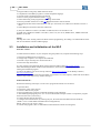
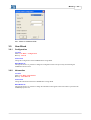
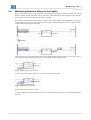
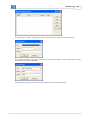
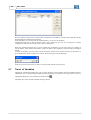
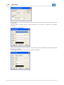
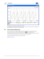
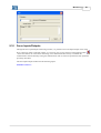
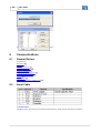
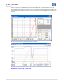
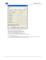
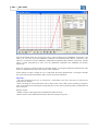
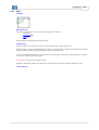
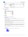
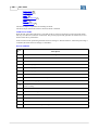
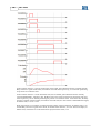
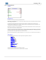
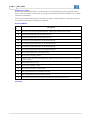
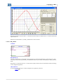
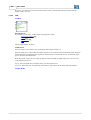
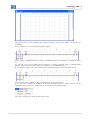
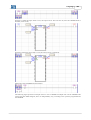
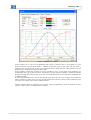
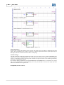
68 WLP V9.90 In the box of the chart properties you can execute following operations: - Set manually the X and Y axis scale - Enable/disable the mouse coordinates - Enable/disable the X and Y axis 3.6.5 Application 3.6.5.1 Create ACCESS Menu: Tools - Application - Create FUNCTION It allows the user to create a new ladder project based on applications 3.6.5.2 313 pre-defined in the WLP. Configurate ACCESS Menu: Tools - Application - Configurate FUNCTION It allows the user to configure an application 3.7 Build 3.7.1 Compile ACCESS Menu: Build - Compile Hot Key: F7 Standard Toolbar: FUNCTION Compiles the project. DESCRIPTION 313 that has been previously created. Menus 69 After compiling, a dialog box is opened showing the possible compiling errors 39 and the location of the errors 39 in the ladder editor. See also the error messages, fatal errors 309 , warnings 312 and information 313 about compiler. 3.7.2 Compile Subroutine/USERFB ACCESS Menu: Build - Compile Hot Key: Ctrl+F7 Standard Toolbar: FUNCTION Compiles the subroutine/USERFB. DESCRIPTION After compiling, a dialog box is opened showing the possible compiling errors 39 and the location of the errors 39 in the ladder editor. See also the error messages, fatal errors 309 , warnings 312 and information 313 about compiler. 3.7.3 Debug ACCESS Menu: Build- Debug Hot Key: Shift+F7 FUNCTION It enables or disables the debugging information. 3.8 Communicate 3.8.1 Download ACCESS Menu: Communicate - Download Hot Key: F8 Communication Toolbar: FUNCTION Writes the user program into the board. IMPORTANT * Check the Communication-Configurations 3.8.2 Upload ACCESS Menu: Communicate - Upload Hot Key: Alt+F8 Communication Toolbar: FUNCTION Reads the user program into the board. 72 . 70 WLP V9.90 IMPORTANT * Check the Communication-Configurations 72 . * Only available for the CFW-11 SoftPLC and the SSW-06 SoftPLC. * For the CFW-11 SoftPLC it is possible to protect this function via password. For more details verify the project properties 34 . 3.8.3 Online Monitoring ACCESS Menu: Comumnication - Online Monitoring Hot Key: F9 Communication Toolbar: FUNCTION Activate or deactivate the oniline monitoring. IMPORTANT * Check the Communication-Configurations 3.8.4 Config Online Monitoring 3.8.4.1 Signed 72 . ACCESS Menu: Communication - Config Online Monitoring - Signed FUNCTION During online monitoring it changes all the monitoring boxes to a format with signal. 3.8.4.2 Not Signed ACCESS Menu: Communication - Config Online Monitoring - Not Signed FUNCTION During online monitoring it changes all the monitoring boxes to a format without signal. 3.8.4.3 Decimal ACCESS Menu: Communication - Config Online Monitoring - Decimal FUNCTION During online monitoring it changes all the monitoring boxes to a decimal format. 3.8.4.4 Hexadecimal ACCESS Menu: Communication - Config Online Monitoring - Hexadecimal FUNCTION During online monitoring it changes all the monitoring boxes to an hexadecimal format. Menus 3.8.4.5 71 Binary ACCESS Menu: Communication - Config Online Monitoring - Binary FUNCTION During online monitoring it changes all the monitoring boxes to a binary format. 3.8.5 Monitoring Variables ACCESS Menu: Communication - Variables Monitoring Hot Key: Shift+F9 Communication Toolbar: 3.8.6 FUNCTION Activate or deactivate the variables monitoring 82 IMPORTANT * Check the Communication-Configurations . 72 . Trend Variables ACCESS Menu: Communication - Trend of Variables Hot Key: Ctrl+F9 Communication Toolbar: FUNCTION Open a dialog showing a trend graphic 84 with the chosen variables IMPORTANT * Check the Communication-Configurations 3.8.7 72 . Monitoring Input/Outputs ACCESS Menu: Communication - I/O Monitoring Hot Key: Alt+F9 Communication Toolbar: FUNCTION Open a dialog that shows the current state of the digital inputs and outputs IMPORTANT * Check the Communication-Configurations 72 . 88 from the PLC and drive. 72 3.8.8 WLP V9.90 Monitoring by HMI ACCESS Menu: Communication - Monitoring by HMI Hot Key: Ctrl+Alt+F9 Communication Toolbar: FUNCTION Open a dialog that shows the Monitoring by HMI Dialog IMPORTANT * Check the Communication-Configurations 3.8.9 72 . Force Inputs/Outputs ACCESS Menu: Communication - Force Inputs/Outputs Communication Toolbar: FUNCTION Open a dialog that shows the Force Inputs/Outputs IMPORTANT * Check the Communication-Configurations 72 . 91 . 3.8.10 General Information ACCESS Menu: Communication - General Information Communication Toolbar: FUNCTION Open a dialog that shows the General Information IMPORTANT * Check the Communication-Configurations 3.8.11 Config ACCESS Menu: Communicate - Config Hot Key: Shift+F8 FUNCTION Configures the communication. 72 . 93 . 90 . Menus 73 Port : COM1 to COM8 and USB. 3.9 User Block 3.9.1 Configuration ACCESS Menu: User Block - Configuration Hot Key: Ctrl+M FUNCTION Change the configuration of the USERFB that is being edited. DESCRIPTION Through this menu it is possible to change the configurations that were previously stored during the USERFB creation wizard. 3.9.2 Information ACCESS Menu: User Block - Information Hot Key: Ctrl+Shift+M FUNCTION Change the information about the USERFB that is being edited. DESCRIPTION Through this menu it is possible to change the information that appears when info button is pressed in the USERFB properties box. 74 3.10 WLP V9.90 Window 3.10.1 Cascade ACCESS Menu: Window - Cascate FUNCTION Cascate the windows of the all opening projects. 3.10.2 Tile Horizontally ACCESS Menu: Window - Tile Horizontally FUNCTION Arranges the windows as horizontal, nonoverlapping tiles. 3.10.3 Tile Vertically ACCESS Menu: Window - Tile Veritcally FUNCTION Arranges the windows as veritcal, nonoverlapping tiles. 3.11 Help 3.11.1 Contents ACCESS Menu: Help - Contents Hot Key: F1 Standard Toolbar: FUNCTION It shows the Help for the current task or command. 3.11.2 About WLP ACCESS Menu: Help - About Hot Key: Ctrl+Shift+A FUNCTION It shows information about the program. Edit Operations 4 Edit Operations 4.1 Selecting Cells 1. Activate the pointer command 2. Click with the left mouse button on a cell and drag the mouse to the desired cell. The selected cell may be deleted by clicking Delete. CLICKING ON THE FIRST CELL DRAGGING TO THE LAST CELL RELEASING THE LEFT MOUSE BUTTON 75 76 4.2 WLP V9.90 Moving Cells 1. Select 75 the desired cells. 2. Click with the left mouse button on a cell and drag it to the desired cell. CLICKING ON THE FIRST CELL DRAGGING TO THE LAST CELL RELEASING THE LEFT MOUSE BUTTON Edit Operations 4.3 77 Pasting Cells 1. Select 75 the desired cells. 2. Copy 36 or cut 36 the cells to the transfer areas. 3. Activate command Paste 36 . 4. Click with the left mouse button on the desired position. 5. Click with the right mouse button to end the operation. 5 Monitoring 5.1 Introduction The online monitoring is executed through the interface of the board and in the same manner as the Ladder program is loaded to the board, i. e., after the compiled Ladder program has been loaded, you can use the WLP program through the interface to display charts and to show through the logic status of the ladder program. By means of the online monitoring you can display the logic status of contacts and coil of the ladder program, as well as display the current values of the word and float markers and the parameter of the drive and board. 78 5.2 WLP V9.90 Toolbar FIGURE : On this toolbar you can find all functions relating to the online monitoring, which are: - LADDER MONITORING - VARIABLES MONITORING - VARIABLESTREND - MONITORING OF INPUTS AND OUTPUTS - MONITORING PARAMETER BY HMI All online monitoring functions can be used individually or jointly, i. e., all function use the same communication channel with the board realized through the shared interface. Please consider that the more monitoring function are used, the more information will be requested from the board which will slow down the monitoring functions. 5.3 Online Monitoring After the Ladder program has been compiled and loaded to the board, you now can monitor the Ladder program by pressing the button online monitoring . Now the WLP tries establishing communication with the board and tests the communication with this board. When no communication erros is detected, following message will be displayed on the status bar at the bottom of the WLP. On the same status bar you can find a blue LED that flashes, indicating the the communication is operating correctly . If some coomunication error is detected, a box will be opened, indicating the detected fault and which required action should be adopted. After that the online monitoring will be disabled. When the online monitoring is active, all editing tools are disabled and the Editing window displays the logic status of the ladder program. Press the online monitoring key again for disabling this function Please find below the graphic presentation of the logic status of coil and contacts during online monitoring : NORMAL OPEN (NO) CONTACT CLOSED NORMAL OPEN (NO) CONTACT OPEN NORMAL CLOSED (NC) CONTACT CLOSED NORMAL CLOSED (NC) CONTACT OPEN COIL ACTIVATED Monitoring 79 COIL DEACTIVATED NEGATED COIL DEACTIVATED NEGETAED COIL DEACTIVATED SET COIL ACTIVATED SET COIL DEACTIVATED RESET COIL ACTIVATED RESET COIL DEACTIVATED POSITIVE TRANSITION COIL ACTIVATED POSITIVE TRANSITION COIL DEACTIVATED NEGATIVE TRANSITION COIL ACTIVATED NEGATIVE TRANSITION COIL DEACTIVATED NOTE! The language to describe the Ladder operation does a comparison to an electric circuit with contactors and their respective contacts. When a contact in the ladder is mentioned as being conducting, it refers to its capability of being giving continuity (logic sequence) to the next program phase. In the same way, an "energized" coil has its contacts in the program logic: - Normally Open - NO: conducting; - Normally Closed - NC: not conducting. Next, an example of ladder online monitoring using 4 digital inputs (each one represented by a NO or NC contact) and 4 coils: 80 WLP V9.90 The previous figure presents the graphic representation of the logic status of the 4 digital inputs when they are deactivated, i.e., when there is no signal at their terminals. Those DI's associated to NO contacts show no conduction, and those associated to NC contacts indicate conduction. The normal coils will be energized if the contact connected to them allows conduction, i.e., the coil input is equal to 1. The negated coils appear as energized only when the contact connected to them is not conducting, i.e., the coil input is equal to 0. In next figure the digital inputs are active, with 24Vdc applied to their terminals. According to the indication, the contact logic status is the opposite of what was presented in the figure 5.4 (NO = conducting and NC = not conducting). Now the logic status of the contacts and coils are exactly contrary the previous ones. Monitoring 5.4 81 Monitoring Numerics Values in the Ladder Some ladder function blocks, as for instance the SCURVE and TCURVE, use numeric variables with word markers, floating markers and board or drive parameters. The monitoring of those functions is done with the mouse click at the connector related to the numeric variable. For example, for monitoring the actual time of a timer that is in the Word marker %MW6000, according to the next figure, you must click with the mouse on the position indicated by means of the next figure, and the variable value monitoring box will appear. The monitoring box can be placed in any place in the ladder editing window; therefore it is necessary only to click on the box and while the mouse key is pressed, to drag it to the desired position. Figure - Monitoring box repositioned. To delete the monitoring box, click on it, select it and then press key DEL. Figure - Monitoring box selected. Undo the selection by clicking on ESC. In order to change the monitoring format click on it with the mouse right button, so that the following menu shows up: 82 WLP V9.90 Figure - Format menu. It is possible to choose the following options in that menu: - With signal - Without signal - Decimal - Hexadecimal - Binary It is also possible to select the format for all the monitoring boxes of the current page, therefore, verify in the option Menu – Communication – Online Monitoring Configuration. 5.5 Ladder Variable Write When online monitoring is active, you can write values in variables of the type bit marker, word markers, float markers, system bit markers, user parameters, system parameters and digital outputs.To write in variables used in contacts or coils, you must give adouble-click on it. To write in variables used in function blocks, you must give a double-click on the variable connector as shown below. After the double-click, following box will be displayed. In this box you must write now the new value to be written and confirm it by key. 5.6 Variables Monitoring Through the variable monitoring dialog box you can check the status of the variables used in the ladder program, indifferent if you are monitoring the ladder program or not. For loading this dialog box, press the variable monitoring button . In the same manner as in the online monitoring, the WLP will try to establish the communication with the board, by testing the communication with this board, and it will execute the same operations described previously. The variable monitoring dialog box has following features : Monitoring 83 For inserting new variables, press the button insert and the following dialog box will be displayed: For executing this dialog, select Type, Address and a representative Symbol. In the example below has been selected the word marker %MW6000: The monitoring dialog box will have following features after pressing the button OK: 84 WLP V9.90 Now the number inserted in the column Value corresponds to the effective variable value acquired from the board through the communication interface. In this dialog box you can also edit the variable, delete it, or move it up and down. Through the menu File at the left bottom corner of the dialog box you can save and open the variable configurations that have been made in the respective dialog box. When the variable monitoring box is active and has been configured, you can write values in variables of type bit marker, word marker, float marker, system bit marker, user parameter, system parameter and digital outputs. To write in variables, you must select with the mouse the variable to be written and click on the button, or give a double-click on the variable to be written. The following box will be displayed In this box you must write the new value to be written and confirm it by the button. 5.7 Trend of Variables Through the variable trend dialog box you can check the status of the variables used in the ladder program, indifferent if you are monitoring the ladder program graphically, for instance, with a pen plotter or not. For loading this dialog box, press the button Variable Trend The dialog box of the variable trend has following feature: . Monitoring 85 All configurations related to the variable trend are in the Graphic menu as shown below:: The variable trend has a slight different operation when compared with the other ones mentioned above. For using this Trend, proceed as follows: 1. Configure the graphic through the option "Configure". 2. Configure the Variables to be plotted through the options"Variable 1 to 6". 3. Start the Trend trough the option "Start Trend". TREND CONFIGURATION 86 WLP V9.90 In this dialog box you can select the variable read cycle which corresponds to the time interval between each reading of the selected variables. The scale of the X shaft corresponds to the time that is available for the graphic visualization. VARIABLES CONFIGURE Select in this dialog box the Type, Address, a representative Symbol the Minimum and the Maximum and the Color of the variable. In the example below has been selected the word marker %MW6001: Monitoring 87 After pressing OK, the dialog box of the variable trend will be as follows: START TREND As during the online monitoring process, when the option "Start Trend" is pressed, the WLP tries to establish the communication with the board and it will test the communication and executes the same operations as described above. After the communication has been established, the Trend will acquire the variables according to the requested cycle and will draft them on the screen as shown below : 88 WLP V9.90 In this dialog box you can also edit and delete the variable. In the menu File at the left bottom corner of the dialog box you can save and open these trend configurations from the dialog box, as well as print the respective trend. 5.8 Inputs/Outputs Monitoring You can check the status of the digital inputs/outputs of the board and drive through the input/outputs monitoring dialog box. Press button Input/Output Monitoring for loading thisdialog box. As during the online monitoring process, the WLP tries to establish the communication with the board and it will test the communication and executes the same operations as described above. The input/output monitoring dialog box has following features: PLC1, PLC2 e POS2 : Monitoring SOFTPLC CFW-11 : SOFTPLC SSW-06 : PLC11-01 and PLC11-02: 89 90 WLP V9.90 SRW01-PTC and SRW01-RCD: The active inputs/outputs are displayed in green color and the inactive inputs/outputs are displayed in gray color. 5.9 Monitoring via the HMI Through the HMI monitoring window, it is possible to monitor and edit the parameter values. In order to load this window, it is necessary only to press the monitoring key on the HMI . In the same manner as in the online monitoring, in this moment the WLP will try to establish the communication with the board by testing the communication with it, and it will perform the same operations previously described. The monitoring box via HMI has the following aspect: Monitoring 5.10 91 Force Inputs/Outputs Through the force inputs/outputs monitoring window, it is possible to force the inputs/outputs value of the drive or board. In order to load this window, it is necessary only to press the force inputs/outputs button . In the same manner as in the online monitoring, in this moment the WLP will try to establish the communication with the board by testing the communication with it, and it will perform the same operations previously described. The force inputs/outputs window has the following aspect: SOFTPLC CFW-11 : 92 WLP V9.90 PLC11-01 and PLC11-02: Monitoring 93 IMPORTANT * Only available for SoftPLC CFW-11, PLC11-01 and PLC11-02. 5.11 General Information (Online) Through the general information window, it is possible to monitoring the general information of the board. In order to load this window, it is necessary only to press the general information button . In the same manner as in the online monitoring, in this moment the WLP will try to establish the communication with the board by testing the communication with it, and it will perform the same operations previously described. The general information window has the following aspect: 5.12 Parameters Value Table It is a tool that allows to read the values of the parameters of the board, clicking on "Upload" button. Also it is possible to transfer values from the list of the dialog to the board clicking on "Download" button. This list can be edited, saved to a file or loaded from a file ".par". Below follow an exemple of a reading process of the parameters values. 94 WLP V9.90 6 Communications 6.1 General Review Comunicação : Download 69 Upload 69 Online Monitoring 70 Variable Monitoring 71 Trend of variables 71 Inputs/Outputs Monitoring 71 Monitoring via the HMI 90 Config 72 Serial Cable 94 Installing/Uninstalling USB Driver 6.2 95 Serial Cable CONNECTION The figure below shows how must be done the RS-232 link (point to point) between PC and drive. Communications 95 A - cable to RS-232 B - connector X4 D - Drive WEG CABLE The figure below indentify the parts of the cable used to RS-232. A - flat cable 6 wires (only 2, 3 and 5 pins of the DB9 connector are used) maximum size 10m. B - X4 connector RJ-11 (6x6) C - female DB9 connector Signal PC (DB9) Drive (XC7) =================================== RXD 2 6 TXD 3 4 GND 5 5 6.3 Installing/Uninstalling USB Driver INSTALLING The procedure below explains the method of installing the USB driver onto the PC, to establish communication between the PC and drives through the USB port. Read it thoroughly before setting up the hardware/software. · Close all applications on your PC. If you are using an anti-virus or firewall software, close them (or disable their function). · After connecting the drive to the USB port of PC, Windows will find a new hardware. The Found New Hardware Wizard will launch. The operational system will ask you for necessary drivers. Choose Install from a list or specific location (Advanced) and click Next. · Ensure the Search for the best driver in these locations and Include this location in the search boxes are 96 WLP V9.90 both checked. · Click Browse. Now you need to enter the path to the driver. Folder "C:\Weg\WLP VX.YZ\DRIVER_USB " contains driver. Choose it and click Next. · If the location you specified is correct, Windows will locate the drivers and proceed with the installation. · After Windows has installed the necessary drivers, you will be notified by a window indicating that the wizard has finished installing the software. Click Finish to complete the installation process. NOTE ! "C:\Weg\WLP VX.YZ\" is the folder where WLP is installed. INSTALLATION CHECK You can check if the installation was succesful from device manager (drive needs to be connected to the PC). · To run device manager, click Start , click Run , type devmgmt.msc, and then click OK. Another way to reach device manager is by clicking on Settings > Control Panel > System > Hardware > Device Manager. · In the device manager window that appears, near the bottom of the list you should find the entry USBIO controlled devices containing WEG USBIO R02. This indicates that the installation was successful. UNINSTALLATION · · · · · Connect the drive to the PC. Open the device manager and expand the entry USBIO controlled devices by clicking the + sign. Now right-click the WEG USBIO R02 and select Uninstall. You will be prompted to confirm the uninstall. Answer by clicking OK. Windows will uninstall the driver and then you can disconnect the drive from the PC. Reconnecting the drive will start over the installation process described previously in Installing USB Driver. 7 Language 7.1 Introduction 7.1.1 Element Structure CONTACT The contact is a Boolean element that transfers the value to the horizontal link at the right side, which is equal to Boolean AND of the horizontal link value at the left side with proper input, output function and associated Boolean variable memory. The contact does not modify the value of the associated Boolean variable. COIL The coil is a Boolean element that transfers the value contained at its input to its output and stores the current value. It can be used only as the last element of the logic. FUNCTION BLOCK The Function Block (FB) is part of a packed control program that may be used in different parts of the same Language 97 or in different programs. The FB function block provides a software solution for some small problems, such as for the creation of a timer pulse, our it can provide a control for a larger part of an equipment or machine, for example, the control of a pressure valve. Comparisons have been made between the FB and the objects present programming oriented by objects. However this concept may be easily understood through the analogy with the hardware. In many cases, the FB can be compared with integrated circuits. EN - Boolean variable indicates if the operation defined by a function can be executed or not. ENO - Boolean variable indicates if the operations are executed successfully or not. In short, these Boolean inputs allow the power flow through the block. 7.1.2 Data Types Address Table PLC1, PLC2, POS2, SOFTPLC CFW-11 and SOFTPLC SSW-06: DATA TYPE PLC1 V2.0X CFW-09 [First] [Last] Qty Retentive Bit %MX1000 Markers %MX1671 672 PLC2 V1.5X CFW-09 [First] [Last] Qty %MX1000 %MX1671 672 BOARDS POS2 V1.6X SCA-05 [First] [Last] Qty %MX1000 %MX1671 672 SOFTPLC V2.0X SOFTPLC V1.4X CFW-11 SSW-06 [First] [First] [Last] Qty [Last] Qty - - - - Volatile Bit %MX2000 1308 %MX2000 1308 %MX2000 1308 %MX5000 1100 %MX5000 1100 Markers %MX3407 %MX3407 %MX3407 %MX6099 %MX6099 Retentive %MW6000 Word Markers %MW6099 100 %MW6000 %MW6099 100 %MW6000 %MW6099 100 - - - - Volatile Word %MW7000 Markers %MW7649 650 %MW7000 %MW7299 300 %MW7000 %MW7649 650 %MW8000 %MW8199 200 %MW8000 %MW8199 200 %SX0 %SX2 2 %SX0 %SX3 4 %SX0 %SX3 3 %SX3000 %SX3040 21 %SX3000 %SX3030 21 %SW0 %SW7 7 %SW0 %SW7 8 %SW0 %SW7 7 %SW3000 %SW3002 3 %SW3003 %SW3005 2 Retentive %M95000 Float Markers %MF9524 25 %M95000 %MF9524 25 %M95000 %MF9524 25 - - - - Volatile Float %MF9000 Markers %MF9174 175 %MF9000 %MF9174 175 %MF9000 %MF9174 175 %MF9000 %MF9199 200 - - System Bit Markers (1) 103 System Word Markers (1) 103 98 WLP V9.90 DATA TYPE PLC1 V2.0X CFW-09 [First] [Last] Qty PLC2 V1.5X CFW-09 [First] [Last] Qty BOARDS POS2 V1.6X SCA-05 [First] [Last] Qty SOFTPLC V2.0X SOFTPLC V1.4X CFW-11 SSW-06 [First] [First] [Last] Qty [Last] Qty User Parameters %UW800 %UW899 100 %UW800 %UW899 100 %UW800 %UW899 100 %UW1010 %UW1049 40 %UW952 %UW969 18 System Parameters %PW750 %PW799 50 %PW750 %PW799 50 %PW750 %PW799 50 %PW0 %PW1009 1100 %PW0 %PW950 951 Drive Parameters %PD0 %PD749 750 %PD0 %PD749 750 %PD0 %PD749 750 - - - - Board´s Digital Inputs %IX1 %IX9 9 %IX1 %IX9 9 %IX1 %IX9 9 - - - - Drive´s Digital Inputs %IX101 %IX106 6 %IX101 %IX106 6 %IX101 %IX106 6 %IX1 %IX14 14 (3) %IX1 %IX6 6 104 Board´s Digital Outputs %QX1 %QX6 6 %QX1 %QX6 6 %QX1 %QX6 6 - - - - Drive´s Digital Outputs %QX101 %QX103 3 %QX101 %QX103 %QX101 %QX103 3 %QX1 %QX11 11 (3) %QX1 %QX3 3 104 Board´s Analog Inputs - - %IW1 1 %IW1 1 - - - - 2 %IW101 %IW102 2 %IW101 %IW102 2 %IW1 %IW4 4 (3) - - Drive´s %IW101 Analog Inputs %IW102 104 Board´s Analog Outputs - - %QW1 %QW2 2 - - - - - - Drive´s Analog Outputs %QW101 %QW102 2 %QW101 %QW102 2 %QW101 %QW102 2 %QW1 %QW4 4 (3) %QW1 %QW2 2 104 USERFB Parameters %PM0 %PM31 32 %PM0 %PM31 32 %PM0 %PM31 32 - - - - Read Words (2) 103 - - %RW0 %RW31 32 - - - - - - Write Words (2) 103 - - %WW0 %WW31 32 - - - - - - Read Bytes (2) 103 - - %RB0 %RB31 32 - - - - - - Language DATA TYPE PLC1 V2.0X CFW-09 [First] [Last] Qty PLC2 V1.5X CFW-09 [First] [Last] Qty BOARDS POS2 V1.6X SCA-05 [First] [Last] Qty 99 SOFTPLC V2.0X SOFTPLC V1.4X CFW-11 SSW-06 [First] [First] [Last] Qty [Last] Qty Write Bytes (2) 103 - - %WB0 %WB31 32 - - - - - - CANOpen Status (2) 103 - - %RS0 %RS63 64 - - - - - - CANOpen Contol (2) 103 - - %WC0 %WC1 2 - - - - - - 100 WLP V9.90 Address Table PLC11-01, PLC11-02, SRW01-PTC, SRW01-RCD and SCA06: BOARDS DATA TYPE PLC11-01 V1.4X PLC11-02 V1.4X CFW-11 [First] [Last] Retentive Bit %MX6100 Markers %MX6483 Qty 384 SRW01-PTC V4.0X SRW01-RCD V4.0X [First] [Last] Qty - - SCA06 V1.0X [First] [Last Qtd %MX6000 2000 %MX7999 (4) 104 Volatile Bit %MX6500 1488 %MX6100 1408 %MX8000 2000 Markers %MX7987 %MX7507 %MX9999 (4) 104 Retentive %MW8200 Word Markers %MW8399 - Volatile Word %MW8400 Markers %MW8999 600 System Bit Markers (1) - - %MW8200 %MW8849 650 %MW1200 0 %MW1299 9 %MW1300 0 %MW1499 9 %SX3064 %SX3070 1000 (4) 104 2000 (4) 104 %SX3000 %SX3111 25 %SX3000 %SX3006 5 System Word %SW3300 Markers (1) %SW3404 9 %SW3300 1 %SW3404 %SW3408 Retentive %M92000 Float Markers %MF9399 200 - - %MF16000 500 %MF16499 (4) 104 Volatile Float %MF9400 Markers %MF9999 600 %MF9000 %MF9174 175 %MF17000 1000 %MF17999 (4) 104 4 103 3 103 Retentive Double Markers - - - - %MD18000 250 %MD18249 (4) 104 Volatile Double Markers - - - - %MD19000 500 %MD19499 (4) 104 User Parameters %UW1300 %UW1499 200 %UW800 %UW899 100 %UW800 %UW999 200 System Parameters %PW1200 %PW1299 100 %PW0 %PW799 800 %PW750 %PW799 50 Drive Parameters %PD0 %PD1049 1050 - - %PD0 %PD749 750 Board´s Digital Inputs %IX101 %IX109 9 %IX1 %IX4 4 - - Drive´s Digital Inputs %IX1 %IX6 6 - - %IX1 %IX3 3 - - Language 101 BOARDS DATA TYPE PLC11-01 V1.4X PLC11-02 V1.4X CFW-11 SRW01-PTC V4.0X SRW01-RCD V4.0X [First] [Last] Qty SCA06 V1.0X [First] [Last] Qty Expansion´s Digital Inputs - - - - %IX101 %IX312 36 Board´s Digital Outputs %QX101 %QX106 6 %QX1 %QX4 4 - - Drive´s Digital Outputs %QX1 %QX3 3 - - %QX1 %QX1 1 Expansion´s Digital Outputs - - - - %QX101 %QX306 18 Board´s %IW101 Analog Inputs 1 - - - - Drive´s Analog Inputs 2 - - %IW1 %IW1 1 %IW2 %IW2 1 %IW1 %IW2 Expansion´s Analog Inputs [First] [Last Qtd Board´s Analog Outputs %QW101 %QW102 2 - - - - Drive´s Analog Outputs %QW1 %QW2 2 - - - - Expansion´s Analog Outputs - - - - - - USERFB Parameters %PM0 %PM31 32 %PM0 %PM31 32 %PM0 %PM31 32 Read Words (2) 103 %RW4200 %RW4299 100 - - - - Write Words %WW4600 %WW4699 (2) 103 100 - - - - Read Bytes (2) 103 %RB4400 %RB4499 100 - - - - Write Bytes (2) 103 %WB4800 %WB4899 100 - - - - - - 102 WLP V9.90 BOARDS DATA TYPE PLC11-01 V1.4X PLC11-02 V1.4X CFW-11 [First] [Last] SRW01-PTC V4.0X SRW01-RCD V4.0X [First] [Last] Qty Qty - SCA06 V1.0X [First] [Last Qtd CANOpen %RS4000 Status (2) 103 %RS4127 128 - - - - CANOpen %WC4136 Contol (2) 103 %WC4137 2 - - - - Address Table CFW700, CFW701, CTW900: DATA TYPE Retentive Bit Markers CARTÕES / EQUIPAMENTOS CFW700 CFW701 CTW900 [First] [First] [First] Qtd Qtd Qtd [Last] [Last [Last - Volatile Bit Markers %MX5000 %MX6099 1100 %MX5000 %MX6099 1100 %MX5000 %MX6099 1100 Retentive Word Markers - - - - - - Volatile Word Markers %MX8000 %MX8199 200 %MX8000 %MX8199 200 %MX8000 %MX8199 200 System Bit Markers (1) 103 %SX3000 %SX3040 23 %SX3000 %SX3040 23 %SX3000 %SX3040 28 System Word Markers (1) 103 %SW3000 %SW3024 13 %SW3000 %SW3024 13 %SW3000 %SW3010 8 Retentive Float Markers - - - - - - Volatile Float Markers %MF9000 %MF9199 200 %MF9000 %MF9199 200 Retentive Double Markers - - - - - - Volatile Double Markers - - - - - - User Parameters %UW1010 %UW1059 50 %UW1010 %UW1059 90 %UW1010 %UW1059 50 System Parameters %PW1000 %PW1003 4 %PW1000 %PW1003 4 %PW1000 %PW1002 3 Drive Parameters %PD0000 %PD0999 - 1000 %PD0000 %PD0999 - 100 %PD0000 %PD0999 - 100 Board´s Digital - - - - Language Inputs Drive´s Digital Inputs %IX1 %IX8 8 %IX1 %IX8 8 %IX1 %IX8 8 Expansion´s Digital Inputs - - - - - - Board´s Digital Outputs - - - - - - Drive´s Digital Outputs %QX1 %QX5 5 %QX1 %QX5 5 %QX1 %QX5 5 Expansion´s Digital Outputs - - - - - - Board´s Analog Inputs - - - - - - Drive´s Analog Inputs %IW1 %IW2 2 %IW1 %IW3 3 %IW1 %IW4 4 Expansion´s Analog Inputs - - - - - - Board´s Analog Outputs - - - - - - Drive´s Analog Outputs %QW1 %QW2 2 %QW1 %QW2 2 %QW1 %QW4 4 Expansion´s Analog Outputs - - - - - - USERFB Parameters %PM0 %PM31 32 %PM0 %PM31 32 %PM0 %PM31 32 Read Words (2) - - - - - - - - - - - - - - - - - - - - - - - - CANOpen Status (2) 103 - - - - - - CANOpen Contol (2) 103 - - - - - - 103 Write Words (2) 103 Read Bytes (2) 103 Write Bytes (2) 103 (1) Verify system marker function 104 (2) Refer to the WSCAN manual (WEG Software CANOpen Config) for further information. 103 104 WLP V9.90 (3) With expansion modules (4) The amount of markers is dynamic according of user need, but included a total of 2000 bytes of retentive memory and 7344 bytes of volatile memory, which will also be used for the internal variables of the blocks. 7.1.3 Functions of the system markers Functions of the system markers - CFW-11 106 - CFW700 108 - CFW701 108 - CTW900 109 - PLC1 104 - PLC2 104 - PLC11-01 e PLC11-02 - POS2 105 - SRW01-PTC 107 - SRW01-RCD 108 - SCA06 108 - SSW06 106 107 PLC1 : MARKER %SX0 %SX2 %SX3 %SW0 %SW1 %SW2 %SW3 %SW4 104 %SW5 105 %SW7 READING FUNCTION Drive Enabling Return Analog Input Alarm Drive Speed Return [rpm] Drive Speed Return [13 bits] Board Error Return Drive Logic State Return Reference Speed Return [rpm] WRITING FUNCTION Drive Enable Fatal Error Reset Generate User Error Drive Logic Command - READING FUNCTION Drive Enabling Return Motor PTC Sensor Input Analog Input Alarm Drive Speed Return [rpm] Drive Speed Return [13 bits] Board Error Return Drive Logic State Return Encoder Input Speed Return [rpm] Reference Speed Return [rpm] WRITING FUNCTION Drive Enable Fatal Error Reset Generate User Error Drive Logic Command - PLC2 : MARKER %SX0 %SX1 %SX2 %SX3 %SW0 %SW1 %SW2 %SW3 %SW4 104 %SW5 105 %SW6 %SW7 %SW4 Drive Logic Command (PLC1/PLC2) : The Word that defines the logic command is formed by 16 bits, 8 high bits and 8 low bits, having the following construction: Language 105 High bits - select the function to be activated when set to 1. Bit 15 - Drive Error Reset; Bit 14 - No function; Bit 13 - Save P169/P170 parameter modifications in theEEPROM; Bit 12 - Local/Remote command; Bit 11 - JOG command; Bit 10 - Direction of rotation; Bit 09 - General Enabling; Bit 08 - Start/Stop. Low bits - determine the desired status for the functions selected with the high bits. Bit 7 - Drive Error Reset: every transition from 01 causes thedrive errors to be reset (except for E24, E25, E26 and E27); Bit 6 - No function / Stop detection. It is not necessary to activatethe corresponding high bit (refer to parameter P310 description); Bit 5 - Save P169/P170 in the EEPROM: 0 = Save, 1 = Not tosave; Bit 4 - Local/Remote command: 0 = Local, 1 = Remote; Bit 3 - JOG command: 0 = Inactive, 1 = Active; Bit 2 - Direction of rotation: 0 = Counter clockwise, 1 = Clockwise; Bit 1 - General Enabling: 0 = Disabled, 1 = Enabled; Bit 0 - Start/Stop: 0 = Stop, 1 = Start. FNOTES ! - The drive will only execute the low bit command if the corresponding high bit is set to 1 (one). If the high bit is set to 0 (zero) then the drive will disregard the corresponding low bit value. - When P221 = 11 (local reference via PLC) and in local mode, or P222 = 11 (remote reference via PLC) and in remote mode, then the bits 0 and 2 (Start/Stop and Direction of Rotation) have no function. In this moment the Start/Stop and Direction of Rotation commands are defined exclusively by the movement and positioning function blocks of the PLC board. In this situation the speed reference will enter in the drive total reference, so that the ramp parameters P100, P101, P102 and P103 have no effect, and the ramps are being generated by the movement and positioning function blocks. - When P224 = 4 (Local Start/Stop via PLC) and in local mode, or P227 = 4 (Remote Start/Stop via PLC) and in remote mode, then the logic command bit 1 and the system marker %SX0 have the same function, enabling the drive. %SW5 Drive Logic Status Return (PLC1/PLC2) : The word that defines the logic status is formed by 16 bits, 8 high bits and 8 low bits, having the following construction: High bits -indicate the status of the associated function; Bit 15 - Active error: 0 = No, 1 = Yes; Bit 14 - PID regulator: 0 = Manual, 1 = Automatic; Bit 13 - Undervoltage: 0 = No, 1 = with; Bit 12 - Local/Remote command: 0 = Local, 1 = Remote; Bit 11 - Jog command: 0 = Inactive, 1 = Active; Bit 10 - Direction of Rotation: 0 = Counter clockwise, 1 = Clockwise; Bit 09 - General Enabling: 0 = Disabled, 1 = Enabled; Bit 08 - Start/Stop: 0 = Start, 1 = Stop; Low bits - indicate the error code number. POS2 : 106 WLP V9.90 MARKER %SX0 %SX2 %SX3 %SW0 %SW1 %SW2 %SW3 %SW5 106 %SW6 %SW7 %SW8 READING FUNCTION Drive Enabling Return Analog Input Alarm Drive Speed Return [rpm] Drive Speed Return [13 bits] Board Error Return Drive Logic State Return Encoder Input Speed Return [rpm] Reference Speed Return [rpm] Virtual Axis Speed Return [rpm] WRITING FUNCTION Drive Enable Fatal Error Reset Generate User Error - %SW5 Drive Logic Status Return (POS2) : It indicates the servo drive actual status, according to below : 0 = Servo drive disabled and without error. 1 = Servo drive ready (enabled and without error). 2 = Servo drive in error status. The HMI display shows the error code. SOFTPLC CFW-11 : MARKER %SX3000 %SX3001 %SX3002 %SX3003 %SX3004 %SX3005 %SX3006 %SX3007 %SX3008 %SX3009 %SX3010 %SX3011 %SX3012 %SX3014 %SX3016 %SX3018 %SX3032 %SX3034 %SX3036 %SX3038 %SX3040 %SW3300 %SW3301 %SW3302 READING FUNCTION General Enabling active Ramp Enabled Speed Direction JOG Local/Remote Fault Undervoltage PID Operation Alarm Configuration Mode HMI Key “1” HMI Key “0” HMI Key “Revert Speed Direction” HMI Key “Local/Remote” HMI Key “JOG” Motor Speed [13 bits] Motor Synchronous Speed [rpm] WRITING FUNCTION General Enablinh Start/Stop Speed Direction JOG Local/Remote Error Reset Speed Reference [13 bits] - READING FUNCTION Rotating Motor General Enabling active In Jog In Acceleration In Current Limit WRITING FUNCTION SOFTPLC SSW-06 : MARKER %SX3000 %SX3001 %SX3002 %SX3003 %SX3004 %SX3005 %SX3006 %SX3007 %SX3008 1=Start/0=Stop 1=General Enabling 1=Jog 0=Clockwise/1=Counterclockwise - Language MARKER %SX3009 %SX3010 %SX3012 %SX3014 %SX3015 %SX3016 %SX3018 %SX3020 %SX3034 %SW3303 %SW3305 READING FUNCTION At Full Voltage With Alarm In Deceleration In Remote In Braking In change of Speed Direction In Counterclockwise sense - WRITING FUNCTION 0=Local/1=Remote 1=Error Reset User Fault User Alarm PLC11-01 and PLC11-02: MARKER %SX3000 %SX3002 %SX3004 %SX3006 %SX3008 %SX3010 %SX3012 %SX3014 %SX3016 %SX3018 %SX3032 %SX3034 %SX3036 %SX3038 %SX3040 %SX3064 %SX3066 %SX3068 %SX3070 %SX3101 %SX3103 %SX3105 %SX3107 %SX3109 %SX3111 %SW3300 %SW3302 %SW3306 %SW3308 %SW3310 %SW3400 %SW3402 %SW3404 READING FUNCTION General Enabling active Ramp Enabled Speed Direction JOG Local/Remote Fault Undervoltage PID Operation Alarm Configuration Mode HMI Key “1” HMI Key “0” HMI Key “Revert Speed Direction” HMI Key “Local/Remote” HMI Key “JOG” Blinker 2Hz Pulse Stop/Run Always 0 Always 1 Motor Speed [13 bits] Motor Synchronous Speed [rpm] Speed Reference [rpm] Alarm Fault Speed - Auxiliar Encoder Control Mode Scan Count WRITING FUNCTION General Enabling Start/Stop Speed Direction JOG Local/Remote Error Reset - READING FUNCTION Reset Local Command 1 Local Command 2 Local Command 3 Motor Running Local/Remote WRITING FUNCTION Reset Local Command 1 Local Command 2 Local Command 3 Local/Remote SRW01-PTC : MARKER %SX3000 %SX3001 %SX3002 %SX3003 %SX3005 %SX3006 107 108 WLP V9.90 MARKER %SW3300 READING FUNCTION PTC WRITING FUNCTION - READING FUNCTION Reset Local Command 1 Local Command 2 Local Command 3 Motor Running Local/Remote WRITING FUNCTION Reset Local Command 1 Local Command 2 Local Command 3 Local/Remote READING FUNCTION Blinker 2Hz Stop/Run Pulse Always 0 Always 1 WRITING FUNCTION - SRW01-RCD : MARKER %SX3000 %SX3001 %SX3002 %SX3003 %SX3005 %SX3006 SCA06 : MARKER %SX3064 %SX3066 %SX3068 %SX3070 %SW3404 %SX3406 %SW3408 Scan Cycles Elapsed Axis Status Real Axis Status Virtual CFW700 e CFW701: MARKER %SX3000 %SX3001 %SX3002 %SX3003 %SX3004 %SX3005 %SX3006 %SX3007 %SX3008 %SX3009 %SX3010 %SX3011 %SX3012 %SX3014 %SX3016 %SX3018 %SX3020 %SX3021 %SX3022 %SX3023 %SX3024 %SX3026 %SX3028 %SX3032 %SX3033 %SX3034 %SX3036 %SX3038 %SX3040 %SW3300 %SW3302 READING FUNCTION General Enabling Motor Running Speed Direction JOG Local/Remoto In Fault In Subvoltage PID Operation Mode In Alarm In Config Mode Active Ramp State of Command Run (Only for CFW700) In Quick Stop In Bypass (Only for CFW701) In Fire Mode (Only for CFW701) Start "1" Keyborad Stop "0" Keyboard Speed Direction Keyboard "Local/Remote" Keyboard "JOG" Keyboard Motor Speed [13 bits] Synchronous Motor Speed [rpm] WRITING FUNCTION General Enabling Start/Stop Speed Direction JOG Local/Remote Fault Reset 2nd Rampa Force Run SoftPlc Torque Reference - Language MARKER %SW3304 %SW3306 %SW3308 %SW3310 %SW3312 %SW3314 %SW3316 %SW3318 %SW3320 %SW3322 %SW3324 READING FUNCTION Motor Speed [rpm] Speed Reference [rpm] Alarm Fault Id Current Flux [13 bits] Iq Current Torque [13 bits] Id* Flux Current Reference [13 bits] Iq* Torque Current Reference [13 bits] Inverter Nominal Current (HD) [A x10] Motor current without filter (P003) [A x10] Motor torque without filter [% x10] WRITING FUNCTION - READING FUNCTION Ready Run Counter-Clockwise JOG Remote With Fault Subvoltage Changing speed direction With Alarm In Config Mode 2nd Ramp Blocked On Acceleration On Deceleration Auto Tunning Start "1" Keyboard Stop "0" Keyboard Speed Direction Keyboard "Local/Remote" Keyboard "JOG" Keyboard Speed Motor [13 bits] Nominal Speed Motor[rpm] Speed Motor [rpm] Speed Reference [rpm] Alarm Fault WRITING FUNCTION General Enable Start Conter-Clockwise JOG Remote Fault Reset Quickly Stop - CTW900: MARKER %SX3000 %SX3001 %SX3002 %SX3003 %SX3004 %SX3005 %SX3006 %SX3007 %SX3008 %SX3009 %SX3010 %SX3011 %SX3012 %SX3013 %SX3014 %SX3016 %SX3018 %SX3020 %SX3021 %SX3022 %SX3024 %SX3026 %SX3028 %SX3032 %SX3033 %SX3034 %SX3036 %SX3038 %SX3040 %SW3300 %SW3302 %SW3304 %SW3306 %SW3308 %SW3310 2nd Ramp Activate Torque Reference - 109 110 7.1.4 WLP V9.90 Compatibility In order to use the ladder blocks under WLP see the following compatibility table. This table presents which blocks are compatible with each board model. PLC1, PLC2, POS2, SOFTPLC CFW-11 and SOFTPLC SSW-06: BOARDS/EQUIPMENT COMPATIBILITY LADDER BLOCK NO CONTACT PLC1 V2.0X CFW-09 ü PLC2 V1.5X CFW-09 ü POS2 V1.6X SCA-05 ü SOFTPLC V2.0X SOFTPLC V1.4X CFW-11 SSW-06 ü ü NC CONTACT ü ü ü ü ü COIL ü ü ü ü ü NEGATE COIL ü ü ü ü ü SET COIL ü ü ü ü ü RESET COIL ü ü ü ü ü PTS COIS ü ü ü ü ü NTS COIL ü ü ü ü ü INPOS ü ü ü - - INBWG ü ü ü - - SCURVE ü ü ü - - TCURVE ü ü ü - - HOME ü ü ü - - ü ü - - MSCANWEG ü ü ü - - SHIFT ü ü ü - - STOP ü ü ü - - JOG ü ü ü - - SETSPEED ü ü ü - - TON ü ü ü ü ü CTU ü ü ü ü ü FOLLOW ü (1) 114 TRANSFER ü ü ü ü MATH ü ü ü ü ü (3) ü 114 COMP ü ü ü ü ü (3) 114 SAT ü ü ü ü ü (3) 114 ü (3) 114 FUNC ü ü ü ü INT2FLOAT ü ü ü ü - FLOAT2INT ü ü ü ü - PID ü ü ü ü - FILTER ü ü ü ü - AUTOREG - - ü - - RXCANWEG ü ü ü - - CTENC ü ü ü - - USERFB ü ü ü - - MUX ü ü ü ü ü DMUX ü ü ü ü ü IDATA ü ü ü ü ü TCURVAR ü ü ü - - Language 111 BOARDS/EQUIPMENT COMPATIBILITY LADDER BLOCK QSTOP PLC1 V2.0X CFW-09 ü SDO - CAM - PLC2 V1.5X CFW-09 ü ü POS2 V1.6X SCA-05 ü SOFTPLC V2.0X SOFTPLC V1.4X CFW-11 SSW-06 - - - - - ü - - (2) 114 CALCCAM - - ü - - SPEED ü ü ü - - RTC USERERR REF MMC - - - ü ü - - ü(5) ü 114 PLC11-01, PLC11-02, SRW01-PTC, SRW01-RCD, SCA06, SSW7000 and CFW500: BOARDS/EQUIPMENT COMPATIBILITY LADDER BLOCK PLC11-01 V1.4X PLC11-02 V1.4X CFW-11 NO CONTACT ü SRW01-PTC V4.0X SRW01-RCD V4.0X ü SCA06 V1.0X SOFTPLC V1.1X SOFTPLC V1.0X SSW7000 CFW500 ü ü ü NC CONTACT ü ü ü ü ü COIL ü ü ü ü ü NEGATE COIL ü ü ü ü ü SET COIL ü ü ü ü ü RESET COIL ü ü ü ü ü PTS COIS ü ü ü ü ü NTS COIL ü ü ü ü ü - - - - - - - - - - - - - - - - - - - - - INPOS ü INBWG ü SETSPEED ü - - - TON ü ü ü ü ü CTU ü ü ü ü ü TRANSFER ü ü ü ü ü MATH ü ü ü (4) 114 ü ü COMP ü ü ü (4) 114 ü ü SAT ü ü ü (4) 114 ü ü FUNC ü ü ü (4) 114 ü ü INT2FLOAT ü ü ü (4) 114 ü ü FLOAT2INT ü ü ü (4) 114 ü ü SCURVE ü TCURVE ü HOME ü FOLLOW ü MSCANWEG ü SHIFT ü STOP ü JOG ü 112 WLP V9.90 BOARDS/EQUIPMENT COMPATIBILITY LADDER BLOCK PLC11-01 V1.4X PLC11-02 V1.4X CFW-11 PID ü FILTER ü SRW01-PTC V4.0X SRW01-RCD V4.0X SCA06 V1.0X SOFTPLC V1.1X SOFTPLC V1.0X SSW7000 CFW500 - ü ü ü ü ü ü - - - - ü ü AUTOREG - - RXCANWEG ü CTENC ü - USERFB ü ü ü (4) MUX ü ü ü ü ü DMUX ü ü ü ü ü IDATA ü ü - ü (4) TCURVAR ü QSTOP SDO ü (2) 114 114 ü ü - - - - - - - - - - - 114 CAM ü - CALCCAM ü - SPEED ü - ü - - RTC USERERR REF MMC MC_Power MC_Reset MC_MoveAbsolut e MC_MoveRelative MC_MoveVelocit y MW_IqControl MC_Stop MC_GearIn MC_GearInPos MC_Phasing MC_GearOut MC_StepAbsSwitc h MC_StepLimitSwi tch MC_StepRefPulse MC_StepDirect MC_FinishHomin g ü ü - ü ü ü ü ü - - ü - - ü - - ü - - ü - - ü - - - - ü - - ü - - - - ü - - ü - - ü - - ü - - ü - - ü - - ü - - - - ü - - - - ü - - ü - - ü - - CFW700, CFW701 e CTW900: Language BOARDS/EQUIPMENT COMPATIBILITY LADDER BLOCK CTW900 NO CONTACT CFW700 CFW701 ü NC CONTACT ü ü COIL ü ü NEGATE COIL ü ü SET COIL ü ü RESET COIL ü ü PTS COIS ü ü NTS COIL ü ü INPOS JOG SETSPEED - - TON ü ü CTU ü ü INBWG SCURVE TCURVE HOME FOLLOW MSCANWEG SHIFT STOP ü TRANSFER ü ü MATH ü ü COMP ü ü SAT ü ü FUNC ü ü INT2FLOAT ü ü FLOAT2INT ü ü PID ü ü FILTER ü ü AUTOREG - RXCANWEG CTENC - - USERFB ü ü MUX ü ü DMUX ü ü IDATA ü ü TCURVAR - QSTOP - SDO - CAM - CALCCAM - SPEED - 113 114 WLP V9.90 BOARDS/EQUIPMENT COMPATIBILITY LADDER BLOCK CFW700 CFW701 CTW900 RTC USERERR REF MMC MC_Power MC_Reset MC_MoveAbsolu te MC_MoveRelativ e MC_MoveVelocit y MC_Stop MC_GearIn MC_GearInPos MC_Phasing MC_GearOut MC_StepAbsSwit ch MC_StepLimitSw itch MC_StepRefPulse MC_StepDirect MC_FinishHomin g - ü ü ü ü ü - - - - - - - - - - - - (1) only via CAN protocol (2) PLC board enabled as the CANOpen master (3) only in integer format (4) possibility of operations in double float. (5) one block at a ladder and only with optional board IOS6 of SSW06 7.1.5 Types of arguments POSITION / POSITION OFFSET The position / offset comprises three parts: · signal · number of revolutions · fraction of revolution Signal : Depending on the chosen data type, the signal comprises a data type and an address or a constant value. The data type of signal may be: · constant · user parameter · bit marker · digital input Language 115 For the constant data type, the value may be: · positive · negative Number of Revolutions : Depending on the chosen data type, the number of revolutions consists in a data type and an address or a constant value. The data type may be: · constant · user parameter · word marker For the constant data type, the value must be programmed according to the unit that has been configured in the project, and the configuration of the field "Fraction of Revolution" is nt required. For the user parameters and the word markers, should be considered for this field the number of revolutions.. Fraction of Revolution : The fraction of revolution consists only in an address, since it shares the same data type of the field "Number of Revolutions". When the data type is constant, this value is ignored and only the constant configured in the field "Number of Revolutions". For the user parameters and the word markers, the considered unit for this field is the pulse number, which may vary between 0 a 65535 pulses, and is equivalent to a range from 0 to 359,99450º. SPEED / SPEED OFFSET Depending on the chosen data type, the speed consists in a data type and an address or a constant value. The speed data type may be: · constant · user parameter · word parameter For the constant data type, the value should be programmed according to the unit configured in the project. For the user parameters and the word marker, the unit to be considered for this field is the RPM (rotation per minute). ACCELERATION / DECELERATION Depending on the chosen data type, the acceleration/deceleration consists in a data type and an address or just a constant value. The acceleration/deceleration data type may be: - constant - user parameter - word marker For the constant data type, the value should be programmed according to the unit configured in the project. For the user parameters and word markers, the unit to be considered for this field is the RPM/s (rotation per minute/second). JERK Depending on the chosen data type, the jerk consists in a data type and an address or constant value. The jerk data type may be: · constant · user parameter 116 WLP V9.90 · word marker For the constant data type, the value should be programmed according to the unit configured in the project. For the user parameters and word markers, the unit to be considered for this field is the RPM/s² (rotation per minute per second square). MODE The mode is always constant. There are two options: · relative · absolute In relative mode it refers to a positioning, starting from its last position. In this case, the direction of rotation of this positioning is given by the signal, i. e., clockwise direction of rotation when positive and counterclockwise direction of rotation, when negative. The absolute mode refers to the machine zero position, but this zero position may be used only when a zero search (HOME block) has been executed previously. DIRECTION OF ROTATION It has 1 data type and 1 address. The data type can be: · constant · bit marker · digital input · user parameter When the data type was constant, we have the following options: · clockwise · counter-clockwise DIRECTION It has 1 data type and 1 address. The data type can be: · constant · bit marker · digital input · user parameter When the data type was constant, we have the following options: · opposite · same AXIS It determines for which axis will be generated the speed and/or position reference. It offers following options: - Real : axis controlled by the drive. - Virtual : axis used by the CAM block as master. NOTE ! The CAM block and the virtual axis will be only available for the POS2 card with firmware version >= 1.50. Language 117 CONTROL It determines the control type that is used for executing the block. It offers following options: - Automatic: as function of the control previously selected for the block. - Speed - Position INTEGER Depending on the chosen data type, the total part consists in a data type and an address or constant value. The data type of the integer part may be: · constant · word marker · user parameter Attention: When the integer part refers to an output result of any block, the constant data type is not allowed. The limits to integer are : · maximum = 32767 · minimun = -32768 FLOAT The float comprises a data type and an address. The float data type may be: · float constant · float marker Attention: When the float refers to an output result of any block, the float constant data type is not allowed. The float limits are: · maximum = 3.402823466e+38F · minimun = 1.175494351e-38F LIMITS The limits consists in 2 parts: · integer 117 / float 117 - maximum · integer 117 / float 117 - minimum INPUTS VALUES / OUTPUT VALUES The values consists in 2 parts: · integer 117 / float 117 - input · integer 117 / float 117 - output CONTROL MODE It determines the type of reference that will be sent to the drive. The data type may be: - constant - user parameter - bit marker - digital input It offers following options : - 0 : speed reference; 118 WLP V9.90 - 1 : torque current reference. TORQUE CURRENT Depending on the chosen data type, the torque current consists in a data type and an address or just a constant value. The data type may be: - constant - user parameter - word marker - float marker The torque current reference is set in percentage of the motor nominal current. AXIS / SLAVE (Used in the MC blocks - Movement Control) It determines for which axis the speed and position reference will be generated. It presents the following options: - Real: axis controlled by the drive. - Virtual: virtual axis. MASTER (Used in the MC blocks - Movement Control) It determines the reference source of speed and/or position for the synchronism master axis. It presents the following options: - Fast Counter: program the function of digital inputs 1 and 2 (P0300 and P0301) for Fast Counter (option 4); configure the count mode in P0500 and the number of pulses per revolution in P0506. - CANopen - Encoder Input: using the EEN1 or EEN2 accessory module on the SCA06 - Virtual Axis RATIO NUMERATOR This argument will be the numerator of the synchronism ratio of the GearIn and GearInPos blocks. The signal will indicate the movement direction: if the value is positive, the movement will be in the same direction as the master, and if the value is negative, the movement will be in the opposite direction of the master. The RatioNumerator argument can be programmed with: - constant - word marker - user parameter RATIO DENOMINATOR This argument will be the denominator of the synchronism ratio of the GearIn and GearInPos blocks. Its value is without signal and must be different from zero. The RatioDenominator argument can be programmed with: - constant - word marker - user parameter POSITION / DISTANCE / SET POSITION / PHASE SHIFT (Used in the MC blocks - Movement Control) This argument can be programmed with a constant value or by means of a double marker. Language 119 The value must be programmed in revolutions. EXAMPLE: 10.5 revolutions, -2.125 revolutions and 0.025 revolution. VELOCITY (Used in the MC blocks - Movement Control) The speed can be programmed with a constant value or by means of a float marker. The value must be programmed in RPM (revolutions per minute). The maximum allowed value is 10,000 RPM. In the MC_MoveVelocity block, the speed value signal will be the movement direction (positive = clockwise and negative = counterclockwise), in the other blocks only positive values will be accepted. ACCELERATION / DECELERATION (Used in the MC blocks - Movement Control) The acceleration/deceleration can be programmed with a constant value or by means of a float marker. The value must be programmed in RPM/s (revolutions per minute per second). The maximum allowed value is 500,000 RPM/s. Only positive values will be accepted. JERK (Used in the MC blocks - Movement Control) The jerk can be programmed with a constant value or by means of a float marker. The value must be programmed in RPM/s2 (revolutions per minute per second squared). The maximum allowed value is 300,000 RPM/s2. Only positive values will be accepted. IQ (Used in the MC blocks - Movement Control) The Iq can be programmed with a constant value or by means of a float marker. The value must be programmed in Arms (Amps rms). IQ RAMP (Used in the MC blocks - Movement Control) The IQ ramp can be programmed with a constant value or by means of a float marker. The value must be programmed in Arms/s (Amps rms per second). DIRECTION (Used in the MC blocks - Movement Control) This argument determines the movement direction. The direction is always constant and can be: • MC_Positive (positive direction) • MC_Negative (negative direction) • MC_SwitchPositive (only in the MC_StepAbsSwitch block – positive direction if AbsSwitch not activated, and negative direction if activated) • MC_SwitchNegative (only in the MC_StepAbsSwitch block – negative direction if AbsSwitch not activated, and positive direction if activated) SWITCH MODE / LIMIT SWITCH MODE (Used in the MC blocks - Movement Control) This argument determines the reading mode of the digital input used as AbsSwitch or LimitSwitch. The Switch Mode / Limit Switch Mode is always constant and can be: • MC_EdgeOn (leading edge) • MC_EdgeOff (falling edge) BUFFER MODE (Used in the MC blocks - Movement Control) This argument determines when and how the block will be executed in case there is another block in execution. 120 WLP V9.90 The Buffer Mode is always constant and can be: • ABORTING • BUFFERED • SINGLE ABORTING When the execution of a block programmed for Aborting starts and another one is in execution, the block in execution will be aborted (canceled) and this new block will be executed immediately. EXAMPLE: Language 121 In the transition from 0 to 1 of the bit marker 6500, the first MC_MoveAbsolute block is executed; thus the Busy and Active signals of this block, bit markers 6501 and 6502 respectively, are set and the positioning for position 10 revolutions starts. In the transition from 0 to 1 of the bit marker 6505, the second MC_MoveAbsolute block is instantly executed; thus, the Busy and Active signals of this block, bit markers 6506 and 6507 respectively, are set and the positioning for position 15 revolutions starts. At the same time, the Busy and Active signals of the first block, bit markers 6501 and 6502, are reset and the CommandAborted signal, bit marker 6503, is set for 1 scan. When the position 15 revolutions is reached, the Done output of the second block, bit marker 6509, is set and the Busy and Active signals of this block, bit markers 6506 and 6507, are reset. The Done output, bit marker 6509, will remain in 1 while the Execute input, bit marker 6505, is set. 122 WLP V9.90 BUFFERED When the block is programmed for Buffered and another block is in execution, the block in execution will continue its movement until the end and this new block will wait to be executed. EXAMPLE: Language 123 In the transition from 0 to 1 of the bit marker 6500, the first MC_MoveAbsolute block is executed; thus the Busy and Active signals of this block, bit markers 6501 and 6502 respectively, are set and the positioning for position 10 revolutions starts. With the transition from 0 to 1 of bit marker 6505, the second MC_MoveAbsolute block starts, but it will wait for the conclusion of the block in execution; thus, the Busy signal of this block, bit marker 6506, is set. When the positioning of 10 revolutions is reached, the first block is concluded; thus, the Busy and Active signals of this block are reset, and the Done output, bit marker 6504, is set to 1 scan. At the same time the execution of the second block starts, the Active signal, bit marker 6507, is set and the search for the position 15 revolutions starts. 124 WLP V9.90 When the position 15 revolutions is reached, the Done output of the second block, bit marker 6509, is set and the Busy and Active signals of this block, bit markers 6506 and 6507, are reset. The Done output, bit marker 6509, will remain in 1 while the Execute input, bit marker 6505, is set. SINGLE In the attempt to execute a block programmed to SINGLE, and if some other block is in execution, this block will go into error 52 and will not be executed. The HMI will show the alarm A00052. EXAMPLE: Language 125 In the transition from 0 to 1 of the bit marker 6500, the first MC_MoveAbsolute block is executed; thus the Busy and Active signals of this block, bit markers 6501 and 6502 respectively, are set and the positioning for position 10 revolutions starts. With the transition from 0 to 1 of the bit marker 6505, the second MC_MoveAbsolute block starts, but since the other block is in execution, an error will occur and the Error signal, bit marker 6509, will be set and the word marker 8400 will contain the value of error 52. The HMI will show the alarm A00052. When the positioning of 10 revolutions is reached, the first block is concluded; thus, the Busy and Active signals of this block are reset, and the Done output, bit marker 6504, is set to 1 scan. With a new transition from 0 to 1 of the bit marker 6505, the second MC_MoveAbsolute block is executed; thus the Busy and Active signals of this block, bit markers 6506 and 6507 respectively, are set and the 126 WLP V9.90 positioning for position 15 revolutions starts. When the position 15 revolutions is reached, the Done output of the second block, bit marker 6510, is set and the Busy and Active signals of this block, bit markers 6506 and 6507, are reset. The Done output remains in 1 while the Execute input, bit marker 6505, is set. UPDATE MODE (Used in the MC blocks - Movement Control) This argument determines whether the maximum speed of the movement will be updated or not during its execution. The Update Mode is always constant and can be: • RISING • ONLINE RISING The maximum speed value is obtained when activating the block in the transition from 0 to 1 of the Execute signal of the block. ONLINE The maximum speed value can be changed during the movement of the block. CAM TABLE (Used in the MC blocks - Movement Control) The Cam Table argument determines which cam table of the CAM curve you wish to select for execution. Its value can be from 1 to 10. The Cam Table argument can be programmed with: - constant - word marker - user parameter TABLE (Used in the MC blocks - Movement Control) The Table argument determines which cam table of the CAM curve will be calculated according to the block arguments. Its value can be from 11 to 20. The Table argument can be programmed with: - constant - word marker - user parameter CAM TABLE ID (Used in the MC blocks - Movement Control) The Cam Table ID argument is the identification of the cam table of the CAM curve for use in the MC_CamIn block. Its value can be from 1 to 20. The Cam Table ID argument can be programmed with: - constant - word marker - user parameter NUMBER OF POINTS (Used in the MC blocks - Movement Control) The Number Of Points argument configures the number of points of the CAM curve, seeing that the initial Language 127 point (zero position of the master and of the slave) is not considered. The number of points cannot be greater than the maximum number of points of the corresponding cam table, previously programmed by means of the CAM PROFILES tool. The Number Of Points argument can be programmed with: - constant - word marker - user parameter MASTER POINTS (Used in the MC blocks - Movement Control) Double marker that configures the position of the master of the first point of this CAM curve. The position of the master in the other points will be according to the content of the double markers following the selected one; for example, if the configured double marker is the double marker 18010, the position of the master axis in the first point will be the content of double marker 18010, the position of the master axis in the second point will be the content of double marker 18011, and so on. The value of the content of the double marker must be programmed in revolutions. EXAMPLE: 1.5 revolutions, 2.125 revolutions and 10.025 revolutions. In case the position of the master of some point is smaller than or equal to the position of the master of the previous point, an error will occur in the block. SLAVE POINTS (Used in the MC blocks - Movement Control) Double marker that configures the position of the slave of the first point of this CAM curve. The position of the slave in the other points will be according to the content of the double markers following the selected one; for example, if the configured double marker is the double marker 18020, the position of the slave axis in the first point will be the content of double marker 18020, the position of the slave axis in the second point will be the content of double marker 18011, and so on. The value of the content of the double marker must be programmed in revolutions. EXAMPLE: 1.5 revolutions, 2.125 revolutions and 10.025 revolutions. CURVE TYPE (Used in the MC blocks - Movement Control) Word marker that configures the type of the curve of the first point of this CAM curve. The type of curve of the other points will be according to the content of the word markers following the selected one; for example, if the configured word marker is the word marker 12000, the type of the curve will be according to the content of word marker 12000, the type of the curve of the second point will be according to the content of the word marker 12001, and so on. The value of the content of the word marker must be: 0 - linear or 1 - cubic spline PERIODIC (Used in the MC blocks - Movement Control) This argument determines whether the execution of the cam table of the CAM curve will be continuous (periodic) or not. The Periodic argument is always constant and can be: • Non-Periodic • Periodic When the cam table of the CAM curve is Non-Periodic, the CAM curve will be executed only once; otherwise, it will be executed continuously. END OF PROFILE (Used in the MC blocks - Moment Control) The End Of Profile signal is pulsed every time the execution of the CAM curve is finished. 128 WLP V9.90 The data type of the End Of Profile can be: • disabled • bit marker • digital output BUSY (Used in the MC blocks -Movement Control) The Busy signal informs if the block was not finished. The data type of the Busy can be: • disabled • bit marker • digital output When the block starts, the Busy signal is set; remaining is this state until the end of the block. ACTIVE (Used in the MC blocks - Movement Control) The Active signal informs if the block is in execution. The data type of the Active can be: • disabled • bit marker • digital output When the block is executed, the Active signal is set; remaining is this state until the end of the block. If the block is in the Aborting mode or no other block is in execution, the Active and Busy signals will have the same signal. COMMAND ABORTED (Used in the MC blocks - Movement Control) The Command Aborted signal informs if the block was aborted (canceled). The data type of the CommandAborted can be: • disabled • bit marker • digital output If the block started and has not finished yet, its movement (Busy signal set), and another block with the Aborting mode is executed, the CommandAborted signal is set and remains while the Executive input is in 1. The Active and Busy signals are reset. ERROR (Used in the MC blocks - Movement Control) The Error signal informs if an error occurred in the attempt to execute the block. The data type of the Error can be: • disabled • bit marker • digital output If an error occurs in the attempt to execute the block, the Error signal is set and remains while the Executive input is in 1. ERROR ID (Used in the MC blocks - Movement Control) While the Error signal is set, the ErrorId will contain the error code. The data type of the ErrorId can be: • disabled Language 129 • word marker • user parameter For further information on errors occurred, refer to the BLOCK ERRORS table. Retentive Block With the Retentive Block option selected, the internal variables of the block will be saved in retentive memory; thus, the status of the block will remain the same after resetting/restarting the drive. 7.1.6 Quick reference LOGIC NOCONTACT - Normally Open Contact 131 NCCONTACT - Normally Closed Contact 131 COIL - Coil 132 NEGCOIL - Negated Coil 133 SETCOIL - Set Coil 134 RESETCOIL - Reset Coil 135 PTSCOIL - Positive Transition Coil 136 NTSCOIL - Negative Transition Coil 137 POSITIONING BLOCKS SCURVE - S Curve 153 TCURVE - T Curve 156 HOME - Search Zero Position 159 TCURVAR - Variable T Curve 165 CAM - Defined Curve 167 SHIFT - Shift 183 MOVEMENT BLOCKS SETSPEED - Set Speed 213 SPEED - Speed 218 JOG - Move 216 REF - Send Reference 220 STOP BLOCKS STOP - Stop 146 QSTOP - Quick Stop 150 GEAR-BOX BLOCKS FOLLOW - Follower 227 AUTOREG - Automatic Register VERIFY BLOCKS INPOS - In Position 239 INBWG - In Motion 241 PLC BLOCKS TON - Timer 243 RTC - Real Time Clock 246 CTU - Incremental Counter PID - PID Control 250 FILTER - First Order Filter 247 253 228 130 WLP V9.90 CTENC - Encoder Counter 255 CALCULATION BLOCKS COMP - Comparator 260 MATH - Arithmetic 261 FUNC - Math Function 268 SAT - Saturation 269 MUX - Multiplexer 270 DEMUX - Demultiplexer 272 TRANSFERENCE BLOCKS TRANSFER - Transfer 273 INT2FL - Integer to Float Conversion FL2INT - Float to Integer Conversion IDATA - Indirect Transfer 276 USERERR - User Error 277 274 275 CAN NETWORK BLOCKS MSCANWEG - CANWEG Master 278 RXCANWEG - Read CANWEG 279 SDO - Service Data Object 279 OTHER BLOCKS USERFB - Subroutine 294 MMC - Multimotor Control TEXT Comment 307 130 7.2 Texto 7.2.1 Comment DESCRIPTION To change the comment, double-click with the mouse left button on the comment line. Type the new text and confirm with Ok. See 42 how to insert a comment on WLP DIALOG Language 7.3 Contacts 7.3.1 NO CONTACT 131 SYMBOL DESCRIPTION Consists of 1 input, 1 output and 1 argument. The argument consists of one data type and one address. The argument data type may be: · bit marker · digital input · digital output · user parameter NOTE: In the user parameter option, the even values correspond to 0, while the odd ones correspond to 1. OPERATION When its argument value is 1, it transfers the signal contained in its input to its output. Otherwise it transfers 0 to the output. CHART EXAMPLE If the bit marker 2000 and the digital input 1 is 0, writes 1 in the bit marker 1000. Otherwise, writes 0. 7.3.2 NC CONTACT SYMBOL DESCRIPTION Consists of 1 input, 1 output and 1 argument. 132 WLP V9.90 The argument consists of one data type and one address. The argument data type may be: · bit marker · digital input · digital output · user parameter NOTE: In the user parameter option, the even values correspond to 0, while the odd ones correspond to 1. OPERATION When its argument value is 0, it transfers the signal contained in its input to its output. Otherwise it transfers 0 to its output. CHART EXAMPLE If the bit marker 2000 and the digital input 1 is 0, writes 1 in the bit marker 1000. Otherwise, writes 0. 7.4 Coils 7.4.1 COIL SYMBOL DESCRIPTION Consists of 1 input and 1 argument. The argument comprises one data type and one address. The argument data type may be: · bit marker · digital output · user parameter NOTE: In the user parameter option, the current value is not saved in the E2PROM memory, i. e. the last value is not recovered. In addition, the even values correspond to 0 or false and the odd ones correspond to 1 Language 133 or true. OPERATION Transfers the signal contained in its input to its argument. CHART SAMPLE If the bit marker 2000 or the digital input 1 is 1, writes 1 in the bit marker 1000. Otherwise, writes 0. 7.4.2 NEG COIL SYMBOL DESCRIPTION Consists of 1 input and 1 argument. The argument consists of one data type and one address. The argument data type may be: · bit marker · digital output · user parameter NOTE: In the user parameter option, the current value is not saved in the E2PROM memory, i. e., the last value is not restored. In addition, the even values correspond to 0 and the odd ones correspond to 1. OPERATION It transfers the negated signal contained in its input to its argument. CHART 134 WLP V9.90 SAMPLE If the bit marker 2000 or the digital input 1 is 1, and the user parameter 800 is 0, write 0 to the digital output 1, otherwise, writes 1. 7.4.3 SET COIL SYMBOL DESCRIPTION Consists of 1 input and 1 argument. The argument consists of one data type and one address. The argument data type may be: · bit marker · digital output · user parameter NOTE: In the user parameter option, the current value is not saved in the E2PROM memory, i. e. the last value is not recovered. In addition, the even values correspond to 0 and the odd ones correspond to 1. OPERATION The argument is set, when the input signal is 1. The argument will be reset only when one component "resets coil" is activated. CHART Language 135 EXAMPLE If the user parameter 801 and the digital output 1 of the drive are 1, or the digital input 1 is 1 and the user parameter 800 is 0, it sets the digital output 1. Otherwise, the output value is maintained. 7.4.4 RESET COIL SYMBOL DESCRIPTION Consists of 1 input and 1 argument. The argument consists of one data type and one address. The argument data type may be: · bit marker · digital output · user parameter NOTE: In the user parameter option, the current value is not saved in the E2PROM memory, i. e., the last value is not recovered. In addition, the even values correspond to 0 and the odd ones correspond to 1. OPERATION When the input signal is 1, the argument is reset. The argument will be set only if a "set coil" component is activated. CHART 136 WLP V9.90 EXAMPLE If the digital input 1 is 1, resets the user parameter 800. Otherwise, the parameter value is maintained. 7.4.5 PTS COIL SYMBOL DESCRIPTION Consists of 1 input and 1 argument. The argument consists of one data type and one address. The argument data type may be: · bit marker · digital output · user parameter NOTE: In the user parameter option, the current value is not saved in the E2PROM memory, i. e., the last value is not restored. In addition, the even values correspond to 0 or false and the odd ones correspond to 1 or true. OPERATION When there is a transition from 0 to1 at the input signal, the argument is set during the scan cycle. Then the argument is reset, even if its input remains at 1. CHART SAMPLE When the digital input 1 commutates from 0 to 1, writes 1 for 1 scan cycle into the bit marker 2000. Language 7.4.6 137 NTS COIL SYMBOL DESCRIPTION Consists of 1 input and 1 argument. The argument consists of one data type and one address. The argument data type may be: · bit marker · digital output · user parameter NOTE: In the user parameter option, the current value is not saved in the E2PROM memory, i. e., the last value is not restored. In addition, the even values correspond to 0 or false and the odd ones correspond to 1 ot true. OPERATION When there is a transition from 1 to 0 at the input signal, the argument is set for one scan cycle. Then the argument is reset, even if its input remains at 0. CHART SAMPLE When the digital input 1 commutates from 1 to 0, writes 1 for 1 scan cycle into the bit marker 2000. 7.4.7 IMMEDIATE COIL SYMBOL DESCRIPTION Consists of 1 input and 1 argument. The argument consists of one data type and one address. 138 WLP V9.90 The argument data type may be: · digital output OPERATION It transfer the signal contained in its input to the programmed digital output. The writing on the digital output occurs at the moment of execution of the instruction, unlike the normal coil where the writing on the digital outputs occurs only at the end of the scan cycle. CHART 7.5 Function Blocks 7.5.1 Controle de Movimento 7.5.1.1 MC_Power SYMBOL DESCRIPTION Enable/Disable the real shaft. The command enable/disable the real shaft will be according to the Enable input. If Enable is 0, the command will be disable, and if it is 1, the command will be enable. When the MC_Power block is used to enable/disable the real shaft, no digital inputs must be programmed for the Enable function (option 1), or an Alarm may occur. ARGUMENTS It is composed of 1 Enable input, 1 Status output and 5 arguments, which are: - Buffer Mode 119 - Busy 128 - Active 128 - Error 128 - Error Id 128 The Enable input is responsible for enabling/disabling the real shaft. Language 139 The Status output informs the status of the real shaft. The Buffer Mode argument can be: - Aborting: when the command for disabling (Enable = 0), the real shaft will be immediately disabled. - Buffered: when the command is for disabling (Enable = 0), the real shaft will be disabled only when all the movement blocks finish. OPERATION MODE When enabling the real shaft for the first time, the drive may operate in position grid, depending on the value of parameter P0773. The position proportional gain (P0159) must be set to obtain a better drive performance. When the real shaft is disabled, the shaft status will be "Disabled". When enabling the real shaft, the shaft status will change to "Standstill". BLOCK ERRORS Error Id Description 66 Drive in the “Errorstop” status (Drive with Fault) 71 P202 different from 4 (PLC). EXAMPLE 140 WLP V9.90 When changing the value of the bit marker 6500 from 0 to 1, Enable input of the MC_Power block, the real shaft is enabled and its status, word marker of system 3406, changes to “Standstill” (%SW3406 = 2). The Status output, bit marker 6501, is set. After the transition from 0 to 1 of the bit marker 6502, the MC_MoveAbsolut block is executed and the positioning for the position 10 revolutions starts. The shaft status is changed to “Discrete Motion” (%SW3406 = 6). While the positioning is executed, the bit marker 6500, Enable input of the MC_Power block, is reset, but since the BufferMode of the MC_Power is configured as “Buffered", the shaft will only be disabled at the conclusion of the positioning. When the positioning is finished, the bit marker 6503, Done output of the MC_MoveAbsolut block, is set for 1 scan cycle and the shaft is disabled (MC_Power.Enable = 0). The shaft status changes to “Disable” (MC_Power.Enable = 0). 7.5.1.2 MC_Reset SYMBOL DESCRIPTION Clears Drive Fault Language 141 When there is a transition from 0 to 1 in the Execute input, the block will be executed. If the configured shaft is in Fault, the shaft status will be in “Errorstop”; when the block is executed, the shaft status will change to “Disabled”. ARGUMENTS It is composed of 1 Execute input, 1 Done output and 4 arguments, which are: - Axis 118 - Error 128 - Error Id 128 - Retentive Block 129 The Execute input is responsible for enabling the block. The Done output informs the instant in which the block is finished. OPERATION MODE When MC_Reset block is executed, the drive does not change the current operating mode. In the execution of the block, the shaft status will change to "Disabled” only if the status was in "Errorstop". BLOCK ERRORS Error Id 71 Description P202 different from 4 (PLC). EXAMPLE With the real shaft in “Errorstop” status (%SW3406 = 1) and a transition from 0 to 1 of the bit marker 6500, the MC_Reset block will be executed and the shaft status will change to “Disabled” (%SW3406 = 0). The Done output, bit marker 6501, will remain set while the Execute input is in 1. If a fault occurs on the drive, the shaft status will change to “Errorstop” (%SW3406 = 1). 142 WLP V9.90 When a transition from 0 to 1 of the bit marker 6500 occurs again, the MC_Reset block will be executed and the shaft status will change to “Disabled” (%SW3406 = 0). The Done output, bit marker 6501, will remain set while the Execute input is in 1. 7.5.1.3 MC_Stop SYMBOL DESCRIPTION It executes a stop. When there is a transition from 0 to 1 in the Execute input, the block will be started and executed according to the configured arguments. A stop will be executed with a deceleration configured in the "Deceleration" argument. When the stop finishes, the Done output goes to 1 for one scan cycle or while the Execute input is in 1. While the Execute input is in 1, no other MC block will be executed. ARGUMENTS It is composed of 1 Execute input, 1 Done output and 9 arguments, which are: - Axis 118 - Deceleration 119 - Busy 128 - Active 128 - Command Aborted 128 - Error 128 - Error Id 128 - Retentive Block 129 The Execute input is responsible for enabling the block. The Done output informs the instant in which the stop is finished. OPERATION MODE When the MC_Stop block is executed, the drive will star operating in position grid and remain this way even after the conclusion of the block. The position proportional gain must be set (P0159) to obtain a better drive performance. In the execution of the block, the shaft status will change to “Stopping”. When the stop is finished and the block is no longer active, the shaft status will change to "Standstill". BLOCK ERRORS Error Description Language Id 64 Deceleration programmed below the minimum allowed. 65 Deceleration programmed above the maximum allowed. 67 Drive in the "Disabled" or “Errorstop” status. 71 P202 different from 4 (PLC). 78 MC block not executed – Internal fault. 93 Jerk programmed below the minimum allowed. 94 Jerk programmed above the maximum allowed. EXAMPLE 143 144 WLP V9.90 In the transition from 0 to 1 of the bit marker 6500, the MC_MoveVelocity block is executed; thus, the Busy and Active signals of this block, bit markers 6501 and 6502 respectively, are set and the movement to reach the speed of 200 RPM starts. The shaft status (%SW3406) changes from 2 (Standstill) to 5 (Continuous Motion). At the moment that the speed reaches 200 RPM, the InVelocity output, bit marker 6505, is set. With the transition from 0 to 1 of the bit marker 6506, the MC_Stop block is instantly executed; thus, the Busy and Active signals of this block, bit markers 6507 and 6508 respectively, are set and the stop starts. At the same time, the Busy, Active and InVelocity signals of the MC_MoveVelocity block, bit markers 6501, Language 145 6502 and 6505, are reset and the CommandAborted signal, bit marker 6503, is set for 1 scan. The shaft status (%SW3406) changes from 5 (Continuous Motion) to 3 (Stopping). When the stop is finished, the Done output of the MC_Stop block, bit marker 6509, is set and remains until the Execute input, bit marker 6506, is set. The shaft status (%SW3406) remains equal to 3 (Stopping) and no other MC block will be executed. With the transition from 0 to 1 of the bit marker 6500, the MC_MoveVelovity block is started, but since the MC_Stop block is active, an error and the Error signal will occur, bit marker 6504, will be set and the word marker 8400 will contain the error value 69. When the Execute input of the MC_Stop block is reset, the Busy, Active and Done signals, bit markers 6507, 6508 and 6509, are reset. The shaft status (%SW3406) changes from 3 (Stopping) to 2 (Standstill) and other MCs blocks can be executed. In the transition from 0 to 1 of the bit marker 6500, the MC_MoveVelocity block is executed, and thus the Busy and Active signals of this block, bit markers 6501 and 6502 respectively, are set and the movement to reach the speed of 200 RPM starts. The shaft status (%SW3406) changes from 2 (Standstill) to 5 (Continuous Motion). At the moment that the speed reaches 200 RPM, the InVelocity output, bit marker 6505, is set. 7.5.1.4 MW_IqControl SYMBOL DESCRIPTION It executes the control of Iq programmed. When there is a transition from 0 to 1 in the Execute input, the block will be started and executed according to the configured arguments. It order to finish the block, it is necessary the execution of another block or the changing of the drive to the "Disabled" or "Errorstop" status. ARGUMENTS It consists of 1 Execute input, 1 InTorque output and 11 arguments, which are: - Axis 118 - Iq 119 - Iq Ramp 119 - Buffer Mode 119 - Update Mode 126 - Busy 128 - Active 128 146 WLP V9.90 - Command Aborted 128 - Error 128 - Error Id 128 - Retentive Block 129 The Execute input is responsible for enabling the block. The InIq output informs the moment when the Iq programmed is reached OPERATION MODE In the execution of the block, the shaft status will change to "Continuous Motion". BLOCK ERRORS Error Id 7.5.1.5 Description 52 Attempt to execute block with BufferMode - Single when another block is active. 67 Drive in the "Disabled" or “Errorstop” status. 69 Drive in the " Stopping " status. 70 Attempt to execute block with BufferMode - Buffered when another block is active and another block is waiting. 71 P202 different from 4 (PLC). 74 Drive in " Homing " status. 78 MC block not executed – Internal fault. 80 Iq programmed above the maximum allowed. 81 IqRamp programmed below the minimum allowed. 82 IqRamp programmed above the maximum allowed. STOP SYMBOL DESCRIPTION It is formed by 1 EN input, 1 ENO output and 4 arguments: - deceleration 115 - mode 147 - control 117 - axis 116 The EN input is responsible for the block enable. Language 147 The ENO output informs the moment when the block is terminated. Mode The mode is always a constant. There are two options avaliable: · feed enable · kill motion OPERATION If the EN input is 0, this block is not active, the ENO output remains at 0. If the EN input goes 1, even for a short time (at least one scan cycle), a stop with trapezoidal profile will be executed, based on the characteristics programmed in the arguments. When the stop has been finished, the ENO output goes 1 for one scan cycle and then returns to 0. Once started, the stop block can not be cancelled until it has been completely finished, even if the EN input changes to 0 before the end of ramp. The feed enable mode causes the block stop while the EN input is 1. As soon as the input EN changes to 0, the previous active positioning block is restored, since the current position do not be higher or equal to the desired one. This can occur if the deceleration of the stop block is too slow. The kill motion mode does not restore the previous positioning if the EN input returns to 0. Note: If a stop is done in the HOME block, it will be always cancelled, even if programmed as feed enable. Important: This block does not change the control way, despite if it is in position loop or in speed loop. FLOWCHART 148 WLP V9.90 CHART - Kill Motion Mode Language 149 Please note that in this case, after the EN input returns to 0, a S-Curve is started, since this S-Curve was being executed before the stop command was given. - Feed Enable Mode EXAMPLE 150 WLP V9.90 When the digital input 1 is 1, a positioning of 100 revolutions is enabled. When the digital input 2 is 1, the stop block is enabled, causing the positioning interruption. After stopping, the digital output 1 of the drive 1 goes 1 during one scan cycle. As soon as the digital input 2 returns to 0, the positioning of 100 revolutions is completed. 7.5.1.6 QSTOP SYMBOL DESCRIPTION It has 1 EN input, 1 ENO output and 4 arguments: - deceleration 115 - position 114 - control 117 - axis 116 The EN input enables the block. The ENO output inform the instant that the movement was finalized. FUNCTION If the EN input was 0, the block is not active and the ENO output is 0. If the EN input goes to 1, the block is enabled. When the board detect a pulse in quickly input and the position elapsed was reached, it starts a stop. When the stop was finalized, the ENO output goes to 1 during a scan cycle. Other movement can only be started if this block was disabled after finished. Quickly Input (marker of encoder) - 8-pin of X8 conector to POS2 or 8-pin of XC9 conector to PLC1 and PLC2 Language 151 Important: This block do not change the control format, keeping the position loop or speed loop. CHART EXAMPLE When the digital input 1 is 1, a 10 turn positioning will be enabled. If the digital input 2 is 1, a fast stop block will be enabled, passed 5 turns, when a pulse occurs at the X8 fast input the positioning will be canceled. When stopping, 1 is written in the bit marker 2001 during one scan cycle. At the moment when the digital input 2 goes back to 0, the positioning will be able to be restarted. 7.5.1.7 POSITION0 SYMBOL DESCRIPTION This block has a function to execute a position control around 0 rpm, or keeping the engine stopped. 152 WLP V9.90 It has 1 EN input, 1 ENO output and 1 argument: - minimum speed - unit: 13 bits The EN input enables the block. The ENO output inform when the block is active. IMPORTANT: block valid only for CFW700 V2.00 or above and the vector control with encoder active (P0202=5). FUNCTION If the EN input was 0, the block is not active and the ENO output is 0. When the EN input is to 1, the following conditions must be satisfied for the block POSITION0 becomes active: - The drive can not be "disabled general" and the parameter P0229 can not be set to 1. In this condition is generated the alarm A702. - Can not be active other POSITION0 block. - The Module of speed reference must be less or equal than the minimum speed configured. If the above conditions have been staisfied, the block allocates the motor shaft in its current position. Then, the ENO output goes to 1, and remains in this state until the EN input remain in 1. When the block POSITION0 becomes active: - The command "Run" from SoftPlc is activated; - The speed reference from SoftPlc goes to 0; - The position control is enabled; - The axis is allocated at the current position recorded by the encoder. EXAMPLE Cuando la entrada digital 1 es 1, el comando "Ejecutar" SoftPLC (% SX3001) está activo. Si el inversor (% SX3000) está habilitado, hay dos situaciones: Language 153 - Si la entrada digital 2 es 0, el bloque POSITION0 está activado y se activa tan pronto como la referencia pis en 13 bits de la unidad es menor o igual que la velocidad mínima configurada. - Si la entrada digital 2 es 1, el POSITION0 bloque está desactivada y el bloque REF está habilitada para una referencia de velocidad de 100 rpm. 7.5.2 Positioning 7.5.2.1 SCURVE SYMBOL DESCRIPTION It is formed by 1 EN input, 1 ENO output and 6 arguments, as follows: - position 114 - speed 115 - acceleration 115 - jerk 115 - mode 116 - axis 116 The EN input is responsible for the block enable. The ENO output goes to 1 when the move has finished. OPERATION If the EN input is 0, the block will not be executed and the ENO output keeps in 0. If EN is activated for at least one scan cycle and there is no other active movement block, a positioning with S-profile will be executed, based on the arguments programmed. When the positioning is finished, the ENO output goes to 1 for on scan cycle and then returns to 0. Important: This block operates with position loop, so, when it stops, it continues in closed loop of position. CINEMATIC EQUATIONS x = x0 + v0*t + (1/2)*a0*t^2 + (1/6)*J*t^3 v = v0 + a0*t + (1/2)*J*t^2 a = a0 + J*t - x = end position - x0 = start position - v = end speed - v0 = start speed - a = end acceleration - a0 = start acceleration - J = jerk 154 WLP V9.90 FLOWCHART CHART Language 155 EXAMPLE When a transition from 0 to 1 is captured at the digital input 1 a positioning is started with 20.5 revolution at a speed of 2000 rpm, with an acceleration of 50000 rpm/s and a jerk of 230000 rpm/s^2, in the clockwise direction of rotation, since the mode is relative and the positioning signal is positive. After the positioning process has been ended it writes 1 during 1 scan cycle to the digital output 1. Remember that the jerk is the derivative of the acceleration as time function. Thus we can conclude that the max. acceleration will be reached at 50000 rpm/s / 230000 rpm/s^2 = 0.22 seconds. 156 7.5.2.2 WLP V9.90 TCURVE SYMBOL DESCRIPTION It is formed by 1 EN input, 1 ENO output and 5 arguments, as follows: - position 114 - speed 115 - acceleration 115 - mode 116 - axis 116 The EN input is responsible for the block enable. The ENO output informs the moment that the block is finished. OPERATION If the EN input is 0, the block will not be executed and the ENO output keeps in 0. If EN is activated for at least one scan cycle and there is no other active movement block, a positioning with trapezoidal profile will be executed, based on the arguments programmed. When the positioning is finished, the ENO output goes to 1 for one scan cycle and then returns to 0. Important: This block operates with position loop, so, when it stops, it continues in closed loop of position. CINEMATIC EQUATIONS x = x0 + v0*t + (1/2)*a*t^2 v = v0 + a*t + (1/2) - x = end position - x0 = start position - v = end speed - v0 = start speed - a = end acceleration FLOWCHART Language CHART 157 158 WLP V9.90 EXAMPLE When a transition from 0 to 1 is captured at the digital input 1, a Tcurve positioning is started in the absolute mode, configued with the signal of the user parameter 800, with the number of revolutions of the user parameter 801 and with the fraction of revolution of the user parameter 802, with the speed of the user parameter 803 and with an acceleration based on the user parameter 804 in rpm/s. Since it is an absolute positioning, is required that a machine zero search has been executed previously. When finished, it writes 1 for one scan cycle at the digital output 1. Language 7.5.2.3 159 HOME SYMBOL DESCRIPTION It is formed by 1 EN input, 1 ZEROSW input, 1 ENO output and 6 arguments, as follows: - direction of rotation 116 - speed 115 - acceleration 115 - offset (signal, number of revolutions, fraction of revolution) 114 - type : - Standard 159 - Immediate 159 - Unidirectional with Sensor 160 - Unidirectional with Sensor and Null Pulsel 160 - Unidirectional with Null Pulse 160 - Bi-Directional with Sensor 160 - Bi-Directional with Sensor and Null Pulse 161 - axis 116 The EN input is responsible for the block enable. The ZEROSW input is responsible for informing the block that the zero machine position has been reached. The ENO output informs the moment when the block has been finished. TYPE Standard It starts with a trapezoidal profile. When the signal in ZEROSW goes to 1, the block reaches the marker. In this moment, the block stop and come back to the marker position. NOTE! If the ZEROSW input was enable when the block starts, it run in opposite direction until ZEROSW goes to 1. After this, it changes its direction and will have the original behaviour. Immediate (*) In this case, the moviment are not executated and the current position is considerated the zero machine. 160 WLP V9.90 NOTE! In this option, this block can be executated without the drive is enabled. It also can be executated during some other positioning function. Uni-Diretional with Sensor (*) This type can be used when the marker is not available and only one direction is required. It starts an trapezoidal profile. When the switch ZEROSW was detected, this current position was considerated the zero machine and the block starts its decceleration until stop. If the ZEROSW input was enabled, the current position was considerated like zero machine and it was not generated the moviment. Uni-Diretional with Sensor and Null Pulse (*) This type can be used when the switch and the marker on encoder were available and only one direction is required. It starts an trapezoidal profile. When the switch ZEROSW was detected, it enabled to reach the marker. When the marker was detected, this current position was considerated the zero machine and the block starts its decceleration until stop. Uni-Diretional with Null Pulse (*) This type can be used when the marker on encoder was available and only one direction is required. When the marker was detected, this current position was considerated the zero machine and the block starts its decceleration until stop. Bi-Diretional with Sensor (*) This type can be used when the marker is not available. It starts with a trapezoidal profile until reach the marker. Then, it makes that the motor invert its direction and it analises when the switch goes to 0 and this position will be the zero machine. Then, it makes that the motor deccelerate and come back to the zero machine position. Language 161 If the block was enabled and the ZEROSW=1, the moviment run in the opositte direction until the ZEROSW=0. This position will be considerated the zero machine. Then the block force the motor deccelerate and came back to zero machine. Bi-Diretional with Sensor and Null Pulse (*) It starts with a trapezoidal profile until reach the switch ZEROSW. Then it inverts its direction until ZEROSW=0. Then it reaches the marker and this position will be the zero machine. The block decelerates and comes back to the zero machine. If the block and the switch ZEROSW were enabled, the block run in oposite direction until ZEROSW=0. Then it reached the marker, decelerated and came back to the zero machine. OPERATION If the EN input is 0, the block is not executed and the ENO output remains at 0. When the EN input is activated, and no other positioning block is active, the zero search is enabled with trapezoidal profile based on the characteristics of the programmed arguments. When there is a pulse present for at least one scan cycle at the ZEROSW input, the search for the zero pulse is started. As soon as the zero pulse is found, the stop process is started and then the shaft returns to the zero pulse position. At this point, the block is finished and the ENO output goes to 1 for one scan cycle and then returns to 0. NOTE: If the block is enabled and the ZEROSW input is 1, the search is started in the opposite direction as programmed, until the ZEROSW input changes to 0. At this moment, the block reverses the direction of rotation and repeats the steps described in the item above. When the block is finished, the found position will be referenced to the programmed offset value that is usually zero. If we program a negative offset with 25 revolutions and we execute a relative positioning with 50 revolutions and 0 fraction of revolution with positive signal, the final position would be 25 revolutions and 0 fraction with positive signal. However if the positioning is in absolute mode, the end position would be of 50 revolutions and 0 fraction of revolution with positive signal and, in fact, 75 revolutions in clockwise direction of rotation, would be done. NOTE: The homing position, depends on the value of the parameter 769, that causes a position advance regarding to the zero pulse. ATTENTION: After the homing, the control remains in position loop. 162 WLP V9.90 FLOWCHART CHART Language - Normal condition - ZEROSW = 0 - Exceptiong - ZEROSW = 1 163 164 WLP V9.90 EXAMPLE Considering that the drive has been reset recently or switched on, when the digital input 1 goes from 0 to 1, activates the homing, if the bit marker 2001 is at 0. The zero pulse search starts after the ZEROSW (%IX2 = zero switch) goes to 1. The motor decelerates and returns to the found zero pulse position plus the value of P769, as soon as the zero pulse is found. The bit marker 2001 is set as soon as the positioning process has been concluded and then a new homing is enabled. Language 7.5.2.4 165 TCURVAR SYMBOL DESCRIPTION It have 1 input EN, 1 output ENO e 6 arguments: - position 114 - speed 165 - acceleration 115 - direction 116 - syncronism 165 - axis 116 The EN input is responsable to enable the block The ENO output informs that the block was finished. Speed This field has 1 data type and 1 address. The data type can be: · encoder (auxiliary encoder of PLC2 or main encoder of POS2) · user parameter · word marker When the data type was user parameter or word marker, the unit is RPM (revolutions per minute). Syncronism This field has 1 data type and 2 addresses or constants, depending on data type. The data type can be: · constant · user parameter · word marker The addresses or constants are destinates to the relationship between master and slave. Important: The syncronism relationship only is applied when the field speed was encoder. FUNCTION If EN=0, the block is not executed and the ENO=0. If 1 pulse (at least 1 scan cycle) was applied to EN and do not have other block active, will be executed a trapezoidal provile positioning where the speed can be changed during the positioning. When the positioning finish, the ENO goes to 1 during 1 scan cycle. Important: This block works in position loop, keeping this feature after its execution. 166 WLP V9.90 FLOWCHART CHART EXAMPLE Language 167 When a transition from 0 to 1 at the digital input 1 is captured, then a positioning will be triggered, with the signal from the user parameter P800, the number of turns from the user parameter P801, the turn fraction from the user parameter P802, the speed in rpm from the user parameter P803 and the acceleration in rpm/s based on the user parameter P804. When finished, it writes 1 during 1 scan cycle at the digital output 1. 7.5.2.5 CAM SYMBOL: DESCRIPTION: This block comprises 1 EN input, 1 ENO output and 2 argument, being: - PROFILE: CAM positioning profile. - Cam Profile Type: - Fixed: the positioning profile is transferred together with the user program and it will not be able to suffer modifications. - Calculable: the positioning profile is transferred together with the user program and it will be able to suffer modifications through the execution of the CALCCAM block. For calculable positioning profiles the following parameters are necessary: · Maximum Number of Points: It is a constant value that configures the maximum number of points that this CAM will be able to have. · First Master Point It is a float marker that configures the position of the master of the first point of this CAM profile, the position of the master of the other points will be according to the contents of the float markers subsequent to the selected one. The contents of the used float markers must have the format of turns, for instance: 1.5 turns, 0.25 turn... Important: If the master position of a point is smaller than the position of the master of the previous point at the moment of the CALCCAM block execution, this CAM profile will not be executed again if the CALCCAM block is not executed again with the use of the correct contents of the 168 WLP V9.90 markers. · First Slave Point It is a float marker that configures the position of the slave of the first point of this CAM profile, the position of the slave of the other points will be according to the contents of the float markers subsequent to the selected one. The contents of the used float markers must have the format of turns, for instance: 1.5 turns, 0.25 turn... · First Curve Type It is a bit marker that configures the interpolation type (0 for linear interpolation and 1 for cubic interpolation) of the first point of this CAM profile. The interpolation type of the other points will be according to the contents of the bit markers subsequent to the selected one. · Number of Points It is a word marker that configures the quantity of points of this CAM profile. NOTES! - If the programmed word marker contains a value bigger than the “Maximum Number of Points ”argument at the moment of the CALCCAM block execution, this CAM profile will not be executed anymore if the CALCCAM block is not executed with the correct contents of the used marker. - At the first scan cycle after the user program download, the CALCCAM block loads the number of points, the point values and the interpolation types for the arguments programmed in the calculable CAM blocks. The EN input is responsible for the block enabling. The ENO output informs the moment the block is started. The block CAM is responsible for the positioning defined in its profile. Fundamentally the CAM device has the function to convert a rotary motion into a forward and backward motion defines by a cam profile. Figure below shows how this cam profile is defined mechanically: Figure - Mechanical CAM. OPERATION: If the EN input is 0, the block is not executed and the ENO output is 0. If the EN input is 1, the block executes the programmed CAM profile, using the virtual axis as master. All WLP positioning and speed blocks can be used for generating the reference for the virtual axis. The CAM block is always relative, i.e., the position of the virtual axis will be considered as master zero position at the start. As soon as the CAM profile is ended, the ENO output goes to 1 during one scan cycle, after that is returns to 0. NOTE! The virtual axis is the used axis as master for the CAM block. From the firmware version 1.50, all Language positioning and motion blocks in POS 2 can generate a reference for the virtual axis: CHART: EXAMPLE: The digital input %IX1 enables the drive. The digital input %IX2 enables the JOG block, which has been programmed for generating a speed 169 170 WLP V9.90 reference for the virtual axis defined by user parameter %UW800 with acceleration defined by the user parameter %UW801. The digital input %IX3 enables the CAM block that from this moment n follows the master according to the profile defined in the parameter PROFILE. As soon as this profile is ended, the digital output %QX3 will be activated. If the digital input %IX3 is always active, the CAM profile will be executed continuously. The profile below was used in the example: Through the online monitoring, following data were acquired: PROPERTIES BOX OF THE CAM BLOCK: Language 171 This box is called by giving a double click on the CAM block. In this box you can execute following operations: - Select the profile used though the "Profile" selection. - Open the profile for editing though the button "Open" . - Create a new profile through the button "Create". - Remove the profile selected through the button "Remove". - Save with other name the profile selected through the button "Save as..." Creating a new CAM profile: For creating a new Cam profile, click on the button "Create. An input box will ask you for the new profile name. After the cam profile editor will open as shown below: 172 WLP V9.90 There are following control in this window: Point table: NOTES - As already mentioned above, the CAM block is always relative. Thus the first point of the table point will be always master = 0 and slave = 0. - Master = virtual axis - Slave = effective axis (drive) Tools for the chart control: Language Tools for the chart control: Cursor values: Relative values for the point selected by the cursor. Master speed: Speed used for the speed, acceleration and slave jerk calculation. 173 174 WLP V9.90 NOTE! - The speed, acceleration and slave jerk should be used as reference for the cam profile development, where they contents are calculated numerically without considering the load, inertia, torque and dynamic of the drive. Adding a new point to the cam profile: A point can be added by activating the button Add Point or Insert Point, or by giving a double click on the chart at the position the new point should be added. The double click can be given on any area of the chart. If there already was an interpolation at this area, the editor will insert this point between the two interpolation points. The point will be always added as interpolation of linear type. When a point is added or inserted through the respective buttons, the master and the slave values enter as zero. In the case the point is inserted, this can cause a profile interruption, since the master position must always increase relating to the origin. In this case the master and the slave value must be edited by clicking on their cells in the point table. The figure below shows the insertion of a point through a double click. To change the interpolation type, click on the type cell on the line that corresponds to the interpolation origin and select the desired one. In the figure below a point has been changed to the cubic type of interpolation. Language 175 Now you can note other values in this curve beside the position, such as speed, acceleration and Jerk, For better viewing of all values, you can use the button "Fit to Screen", as shown below. In the same way we can select one of the values and use the button "Apply selected Zoom". In the example below a zoom has been given for the speed. 176 WLP V9.90 Another important tool to be mentioned is the cursor. In the example below the cursor is positioned on the point of the maximum speed. Please consider that the speed, acceleration and slave jerk values depend on the master speed. Thus we recommend changing them in order to simulate them very near the effective values. In the figure below the master speed will be changed to 1000 rpm and we will analyze the cursor at the same position. Language 177 During the cam profile design all these values must be considered since they may or not be executed due to the mechanical, electroelectronic limits of the installed equipment. As the acceleration and the jerk charts are determined by considering the interpolation between two points at the junctions between the linear interpolations, the acceleration and jerk will be displayed as zero. However theoretically it is known that in a speed step the acceleration and jerk is infinitely variable. In the practice the acceleration and jerk depends at this moment on the mechanical, electrical and electronic limitations of the involved equipment. These speed steps should be noted and considered in the cam profile design. Figure below shows the condition as example. The CAM block has two different interpolation types: the linear and the cubic. Following equations are used: - Linear : 178 WLP V9.90 - Cubic : Were: pe = slave position ve = slave speed ae = slave acceleration je = slave jerk pm = master position vm = master speed pim = initial master position pfm = final master position pie = initial slave position pfe = final slave position a = coefficient calculated bit the CAM editor b = coefficient calculated bit the CAM editor c = coefficient calculated bit the CAM editor Changing one point in the cam profile: One point in the cam profile can be changed through the point table by the direct editing or by moving the point in the chart. To move the point in the chart, place the cursor on the point which will be marked by a red square. Click on this red square and maintain the mouse activated and draw it to the new position. Clicking on the point, the point table will be displaced to the desired point, selecting the related cell. The moving operation of the chart point is interactive. The whole profile is calculated at every change of the point. The new point can be viewed in the point table. Removing a point in the cam profile: The point is remover directly on the point table. Select one of the cells relating to the point and click on the button "Remove Point". Zoom of a determined chart area: Click with the cursor on one of the edges of the region that should be zoomed and maintain the mouse button activated. Move the mouse to mark the region. At this moment a rectangle will be displayed on the chart. Release the mouse button and give a double click on this rectangle. Please find below an example of this zoom Language 179 Moving the chart: Press the key SHIFT and click with the cursor on the chart. Maintain the mouse button compressed. Move the cursor and the chart will move jointly. Chart Menu: To access the chart menu, place the cursor and click with the right mouse button on the chart area. Following menu will be displayed. In this menu following operations can be executed: - Enable/disable mouse coordinates - Enable/disable x and y axis - Execute Fit to Screen operations - Execute Fit to Window operations - Open the box with the chart properties Figure below shows the box with the chart properties. 180 WLP V9.90 In the box of the chart properties you can execute following operations: - Set manually the X and Y axis scale - Enable/disable the mouse coordinates - Enable/disable the X and Y axis 7.5.2.6 CALCCAM SYMBOL DESCRIPTION It is composed by 1 EN input and 1 ENO output. The EN input is responsible for the block enabling. The ENO output informs the instant when the block is finished. The CALCCAM block is responsible for the calculable CAM 167 blocks calculation (the CAM block profile type defined as calculable), according to the argument contents of these CAM blocks. OPERATION When the EN input changes from 0 to 1, the block is executed. By finishing the calculable CAM blocks calculation, the ENO output changes to 1 during 1 scan cycle, returning later to 0. NOTE! At the first scan cycle after the download of the user program, the CALCCAM block loads de number of points, the values of the points and the interpolation types for the programmed arguments in the calculable CAM blocks. EXAMPLE Ladder: Language CAM block properties: CAM profile: 181 182 WLP V9.90 After the download of the user program the value 3 will be loaded into the %MW6000 word marker. The values 0.75, 0.95 and 1.0 into the %MF9500, %MF9501 and %MF9502 float markers, respectively. The values 0.0, 10.0 and 0.0 into the %MF9503, %MF9504 and %MF9505 float markers, respectively. And the values 0 (linear interpolation), 0 and 0 into the %MX1000, %MX1001 and %MX1002 bit markers, respectively. When it is necessary to change a point of a calculable profile, it is enough to change the desired points at the respective defined markers and to execute the CALCCAM block. In this example, in order to change the “toy” CAM profile previously demonstrated, it is enough to load the new values into the mentioned markers and to execute the CALCCAM block. Important: - The CALCCAM block will not be executed if a CAM block were active and the error E68 will be generated on its attempt. - When executing the CALCCAM block with a marker used in the CAM profile containing an improper value, on the attempt of executing this CAM profile the error E53 will be generated and this CAM block will not be executed. Improper Values: - Number of Points value bigger than the Maximum Number of Points. - Master Position value smaller than the Master Position of the previous point. Language 7.5.2.7 183 SHIFT SYMBOL DESCRIPTION It consists of 1 EN input, 1 ENO output and 3 arguments, as follows: - increment - float result 117 - axis 116 The EN input is responsible for the block enable. OPERATION If the EN input is 0, the block will not be executed and the ENO output reminas at 0. If the EN input is 1 and no positioning block is active, excepting the block Follow, then the block increments the motor shaft position by the positioning increment value per second. As soon as the EN input changes to 0, the position increment stops and the ENO output changes to 1 during a scan cycle, and then returns to 0 again. NOTE: The increment can be updated online. Important: This block operates in position loop and remains in this status even after ending the work. FLOW CHART 184 WLP V9.90 CHART EXAMPLE Language 185 When the digital input 1 is activated, the motor shaft will run 360º within one second in the clockwise direction of rotation. 7.5.2.8 MC_MoveAbsolute SYMBOL DESCRIPTION It executes a positioning for the absolute position programmed. When there is a transition from 0 to 1 in the Execute input, the block will be started and executed according to the configured arguments. A positioning for the absolute position configured in the "Position" argument will be executed, with a maximum speed configured in the “Velocity” argument and an acceleration/deceleration configured in the “Acceleration" and “Deceleration" arguments. Depending on the distance of the positioning and the acceleration and deceleration values, the motor speed will not reach the maximum configured speed. The positioning direction will depend on the current position of the motor and the position configure. If the current position is smaller than the configured position, the positioning will be in the positive direction (clockwise) and if the current position is greater than the configured position, the positioning will be in the negative direction (counterclockwise). When the positioning finishes, the Done output goes to 1 for one scan cycle or while the Execute input is in 1. ARGUMENTS It is composed of 1 Execute input, 1 Done output and 14 arguments, which are: - Axis 118 - Position 118 - Velocity 119 - Aceleration 119 - Deceleration 119 186 WLP V9.90 - Buffer Mode 119 - Update Mode 126 - Busy 128 - Active 128 - Command Aborted 128 - Error 128 - Error Id 128 - Retentive Block 129 The Execute input is responsible for enabling the block. The Done output informs the instant in which the block is finished. OPERATING MODE When the MC_MoveAbsolute block is executed, the drive will start operating in position grid and remain this way even after the conclusion of the block. The position proportional gain must be set (P0159) so as to obtain a better drive performance. In the execution of the positioning the shaft status will change to “Discrete Motion”. When the positioning is concluded, the shaft status will change to “Standstill”. BLOCK ERRORS Error Id Description 52 Attempt to execute block with BufferMode - Single when another block is active. 60 Speed programmed below the minimum allowed. 61 Speed programmed above the maximum allowed. 62 Acceleration programmed below the minimum allowed. 63 Acceleration programmed above the maximum allowed. 64 Deceleration programmed below the minimum allowed. 65 Deceleration programmed above the maximum allowed. 67 Drive in the "Disabled" or “Errorstop” status. 69 Drive in the " Stopping " status. 70 Attempt to execute block with BufferMode - Buffered when another block is active and another block is waiting. 71 P202 different from 4 (PLC). 74 Drive in the " Homing " status. 78 MC block not executed – Internal fault. 93 Jerk programmed below the minimum allowed. 94 Jerk programmed above the maximum allowed. 95 It is not allowed to execute positioning with Jerk when another block is active. Language EXAMPLE 187 188 WLP V9.90 In the transition from 0 to 1, the bit marker 6500, the first MC_MoveAbsolute block is executed; thus the Busy and Active signals of this block, bit markers 6501 and 6502 respectively, are set and the positioning for position 10 revolutions starts. In the transition from 0 to 1 of the bit marker 6505, the second MC_MoveAbsolute block is instantly executed (BufferMode - Aborting); thus, the Busy and Active signals of this block, bit markers 6506 and 6507 respectively, are set and the positioning for position 15 revolutions starts. At the same time, the Busy and Active signals of the first block, bit markers 6501 and 6502, are reset and the CommandAborted signal, bit marker 6503, is set for 1 scan. When the position 15 revolutions is reached, the Done output of the second block, bit marker 6509, is set and the Busy and Active signals of this block, bit markers 6506 and 6507, are reset. The Done output, bit marker 6509, will remain in 1 while the Execute input, bit marker 6505, is set. Language 7.5.2.9 189 MC_MoveRelative SYMBOL DESCRIPTION It executes a positioning with the programmed distance. When there is a transition from 0 to 1 in the Execute input, the block will be started and executed according to the configured arguments. A positioning with the displacement configured in the “Distance” argument will be executed, with a maximum speed configured in the “Velocity” argument and an acceleration/deceleration configured in the “Acceleration" and “Deceleration" arguments. Depending on the distance of the positioning and the acceleration and deceleration values, the motor speed will not reach the maximum configured speed. The direction of the positioning will depend on the configured distance signal. If the distance is greater than zero, the positioning will be in the positive direction (clockwise) and if the distance is smaller than zero, the positioning will be in the negative direction (counterclockwise). When the positioning finishes, the Done output goes to 1 for one scan cycle or while the Execute input is in 1. ARGUMENTS It is composed of 1 Execute input, 1 Done output and 14 arguments, which are: - Axis 118 - Distance 118 - Velocity 119 - Aceleration 119 - Deceleration 119 - Buffer Mode 119 - Update Mode 126 - Busy 128 - Active 128 - Command Aborted 128 - Error 128 - Error Id 128 - Retentive Block 129 The Execute input is responsible for enabling the block. The Done output informs the instant in which the block is finished. 190 WLP V9.90 OPERATING MODE When the MC_Moverelative block is executed, the drive will start operating in position grid and remains this way after the conclusion of the block. The position proportional gain must be set (P0159) so as to obtain a better drive performance. In the execution of the positioning, the shaft status will change to “Discrete Motion”. When the positioning is concluded, the shaft status will change to “Standstill”. BLOCK ERRORS Error Id Description 52 Attempt to execute block with BufferMode - Single when another block is active. 60 Speed programmed below the minimum allowed. 61 Speed programmed above the maximum allowed. 62 Acceleration programmed below the minimum allowed. 63 Acceleration programmed above the maximum allowed. 64 Deceleration programmed below the minimum allowed. 65 Deceleration programmed above the maximum allowed. 67 Drive in the "Disabled" or “Errorstop” status. 69 Drive in the " Stopping " status. 70 Attempt to execute block with BufferMode - Buffered when another block is active and another block is waiting. 71 P202 different from 4 (PLC). 74 Drive in the " Homing " status. 78 MC block not executed – Internal fault. 93 Jerk programmed below the minimum allowed. 94 Jerk programmed above the maximum allowed. 95 It is not allowed to execute positioning with Jerk when another block is active. EXAMPLE Language Complete execution of the two blocks: 191 192 WLP V9.90 In the transition from 0 to 1, the bit marker 6500, the first MC_MoveRelative block is executed; thus, the Busy and Active signals of this block, bit markers 6501 and 6502 respectively, are set and the positioning of 10 revolutions starts. When the positioning of 10 revolutions, the first block is concluded; thus, the Busy and Active signals of this block are reset and the Done output, bit marker 6504, is set for 1 scan. With the transition from 0 to 1 of the bit marker 6505, the second MC_MoveRelative block is executed; thus, the Busy and Active signals of this block, bit markers 6506 and 6507 respectively, are set and the positioning for position 5 revolutions starts. When the positioning for 5 revolutions finishes, the Done output of the second block, bit marker 6509, is set and the Busy and Active signals of this block, bit markers 6506 and 6507, are reset. The Done output Language 193 remains in 1 while the Execute input, bit marker 6505, is set. Second block canceling the first block: In the transition from 0 to 1 of the bit marker 6500, the first MC_MoveRelative block is executed; thus, the Busy and Active signals of this block, bit markers 6501 and 6502 respectively, are set and the positioning for 10 revolutions starts. With the transition from 0 to 1 of the bit marker 6505, the second MC_MoveRelative block is instantly executed (BufferMode - Aborting); thus, the Busy and Active signals of this block, bit markers 6506 and 6507 respectively, are set and the positioning for 5 revolutions starts. At the same time, the Busy and Active signals of the first block, bit markers 6501 and 6502, are reset and the CommandAborted signal, bit marker 6503, is set for 1 scan. 194 WLP V9.90 When the positioning of 5 revolutions finishes, the Done output of the second block, bit marker 6509, is set and the Busy and Active signals of this block, bit markers 6506 and 6507, are reset. The Done output remains in 1 while the Execute input, bit marker 6505, is set. 7.5.2.10 MC_StepAbsSwitch SYMBOL DESCRIPTION It executes the search of the position of the AbsSwitch. When there is a transition from 0 to 1 in the Execute input, the block will be started and executed according to the configured arguments. The AbsSwitch can only be connected to digital inputs 1, 2 or 3, seeing that the programmed function of the digital input must be in accordance with the "SwitchMode" argument. If SwitchMode is configured as MC_EdgeOn (leading edge), the function of the digital input (P0300, P0301 or P0302) must be “store position - leading edge" (option 8). If the SwitchMode is configured as MC_EdgeOff (falling edge), the function of the digital input (P0300, P0301 or P0302) must be “store position - falling edge” (option 9). AbsSwitch will be considered the first digital input configured according to SwitchMode from digital input 1. If no digital inputs are configured according to SwitchMode, error 77 will occur in the block and it will not be executed. If when searching the AbsSwitch position, the LitmitSwitch position is reached, the movement will change direction up to the AbsSwitch position. The search will be executed with the speed configured in the “Velocity” argument and an acceleration/deceleration configured in the “Standard Profile”. With the execution of the MC_StepAbsSwitch block, the user’s reference position (P0052 and P0053) is not changed. Language 195 When the search finishes, the Done output goes to 1 during a scan cycle or while the Execute input is in 1. ARGUMENTS It is composed of 1 Execute input, 1 Done output and 10 arguments, which are: - Axis 118 - Direction 119 - Switch Mode 119 - Velocity 119 - Busy 128 - Active 128 - Command Aborted 128 - Error 128 - Error Id 128 - Retentive Block 129 The Execute input is responsible for enabling the block. The Done output informs the instant in which the block is finished. OPERATING MODE When the MC_StepAbsSwitch block is executed, the drive will start operating in position grid and remain this way even after the conclusion of the block. The position proportional gain must be set (P0159) so as to obtain a better drive performance. In the execution of the block, the Shaft Status will change to “Homing” and will remain this way until the execution of the MC_StepRefPulse, MC_StepDirect or MC_FinishHoming blocks. BLOCK ERRORS Error Id Description 60 Speed programmed below the minimum allowed. 61 Speed programmed above the maximum allowed. 67 Drive in the "Disabled" or “Errorstop” status. 69 Drive in the "Stopping" status. 71 P202 different from 4 (PLC). 76 State of the Drive different from “Standstill” or “Homing”. 77 Digital inputs 1, 2 and 3 not configured according to “SwitchMode”. EXAMPLE 196 WLP V9.90 With the transition from 0 to 1 of the bit marker 6500, the MC_StepAbsSwitch block is executed; thus, the Busy and Active signals of this block, bit markers 6501 and 6502 respectively, are set and the search of the AbsSwitch starts. In case 1, when the block is executed, the AbsSwitch is not activated; since the "Direction” argument is configured as "MC_SwitchNegative", the movement will be in the negative direction. When a falling edge in AbsSwitch (SwitchMode = MC_EdgeOff) occurs, the motor stops and returns to the position in which the edge occurred. In case 2, when the block is executed, the AbsSwitch is activated; since the "Direction” argument is configured as "MC_SwitchNegative", the movement will be in the positive direction and, when leaving the AbsSwitch, the motor stops and changes the movement to the negative direction. When a falling edge in AbsSwitch (SwitchMode = MC_EdgeOff) occurs, the motor stops and returns to the position in which the edge occurred. In case 3, when the block is executed, the AbsSwitch is not activated; since the "Direction” argument is configured as "MC_SwitchNegative", the movement will be in the negative direction. But when the LimitSwitch is found, the motor stops and changes the movement to the positive direction. When leaving the AbsSwitch, the motor stops again and changes the movement to the negative direction. When a falling edge in AbsSwitch (SwitchMode = MC_EdgeOff) occurs, the motor stops and returns to the position in which the edge occurred. All the movements are performed with an acceleration/deceleration programmed in the "Standard Profile", except when the LimitSwitch is found, when the motor stops instantly. When returning to the falling edge position of the AbsSwitch, the Done output of the block, bit marker 6503, is set and the Busy and Active signals of this block, bit marker 6501 and 6502, are reset. The Done output, bit marker 6503, will remain in 1 while the Execute input, bit marker 6500, is set. Language 197 7.5.2.11 MC_StepLimitSwitch SYMBOL DESCRIPTION It executes the search of the position of the LimitSwitch. When there is a transition from 0 to 1 in the Execute input, the block will be started and executed according to the configured arguments. The AbsSwitch can only be connected to digital inputs 1, 2 or 3, seeing that the programmed function of the digital input must be in accordance with the "LimitSwitchMode" argument and the “Direction” argument, according to the table below: Direction Limit Switch Mode Digital Input Function MC_Positive MC_EdgeOn Limit switch clockwise active high (option 12) MC_ Positive MC_EdgeOff Limit switch clockwise active low (option 13) MC_Negative MC_EdgeOn Limit switch counterclockwise active high (option 14) MC_Negative MC_EdgeOff Limit switch counterclockwise active low (option 15) It will be considered LitmSwitch the first digital input configured according to the table, from digital input 1. If no digital inputs are configured according to LimitSwitchMode and Direction, error 77 in the block will occur and it will not be executed. 198 WLP V9.90 The search will be executed with the speed configured in the “Velocity” argument and an acceleration/deceleration configured in the “Standard Profile”. With the execution of the MC_StepLimitSwitch block, the user’s reference position (P0052 and P0053) is not changed. When the search finishes, the Done output goes to 1 during a scan cycle or while the Execute input is in 1. ARGUMENTS It is composed of 1 Execute input, 1 Done output and 10 arguments, which are: - Axis 118 - Direction 119 - Limit Switch Mode 119 - Velocity 119 - Busy 128 - Active 128 - Command Aborted 128 - Error 128 - Error Id 128 - Retentive Block 129 The Execute input is responsible for enabling the block. The Done output informs the instant in which the block is finished. OPERATING MODE When the MC_StepLimitSwitch block is executed, the drive will operate in position grid and remain this way even after the conclusion of the block. The position proportional gain must be set (P0159) so as to obtain a better drive performance. In the execution of the block, the shaft status will change to “Homing” and will remain this way until the execution of the MC_StepRefPulse, MC_StepDirect or MC_FinishHoming blocks. BLOCK ERRORS Error Id Description 60 Speed programmed below the minimum allowed. 61 Speed programmed above the maximum allowed. 67 Drive in the "Disabled" or “Errorstop” status. 69 Drive in the "Stopping" status. 71 P202 different from 4 (PLC). 76 Status of the Drive different from “Standstill” or “Homing”. 77 Digital inputs 1, 2 and 3 not configured according to “LimitSwitchMode”. EXAMPLE Language 199 With the transition from 0 to 1 of bit marker 6500, the MC_StepLimitSwitch block is executed; thus, the Busy and Active signals of this block, bit markers 6501 and 6502 respectively, are set and the search of the LimitSwitch starts. In case 1, when the block is executed, the LimitSwitch is not activated; since the "Direction” argument is configured as "MC_Negative", the movement will be in the negative direction. When a falling edge occurs in LimitSwitch (SwitchMode = MC_EdgeOn), the motor stops and returns to the position in which the edge occurred. In case 2, when the block is executed, the LimitSwitch is activated, but even with the "Direction” argument configured as "MC_Negative", the movement will be in the positive direction and, when leaving the LimitSwitch, the motor stops and changes the movement to the negative direction. When the leading edge in LimitSwitch (SwitchMode = MC_EdgeOn) occurs, the motor stops and returns to the position in which the edge occurred. All the movements are performed with an acceleration/deceleration programmed in the "Standard Profile", except when the LimitSwitch is found, case in which the motor stops instantly. When returning to the leading edge position of the LimitSwitch, the Done output of the block, bit marker 6503, is set and the Busy and Active signals of this block, bit marker 6501 and 6502, are reset. The Done output, bit marker 6503, will remain in 1 while the Execute input, bit marker 6500, is set. 200 WLP V9.90 7.5.2.12 MC_StepRefPulse SYMBOL DESCRIPTION It executes the search for the null pulse. When there is a transition from 0 to 1 in the Execute input, the block will be started and executed according to the configured arguments. The search will be executed with the speed configured in the “Velocity” argument and an acceleration/deceleration configured in the “Standard Profile”. When the search finishes, the user’s reference position (P0052 and P0053) is changed to the “SetPosition” argument value and the Done output goes to 1 during a scan cycle or while the Execute input is in 1. ARGUMENTS It is composed of 1 Execute input, 1 Done output and 10 arguments, which are: - Axis 118 - Direction 119 - Velocity 119 - SetPosition 118 - Busy 128 - Active 128 - Command Aborted 128 - Error 128 - Error Id 128 - Retentive Block 129 The Execute input is responsible for enabling the block. The Done output informs the instant in which the block is finished. OPERATING MODE When the MC_StepRefPulse block is executed, the drive will start operating in position grid and remain so even after the conclusion of the block. The position proportional gain must be set (P0159) so as to obtain a better drive performance. In the execution of the block, the shaft status will change to “Homing”. When concluding the search, the shaft status will change to “Standstill”. BLOCK ERRORS Error Id Description Language 60 Speed programmed below the minimum allowed. 61 Speed programmed above the maximum allowed. 67 Drive in the "Disabled" or “Errorstop” status. 69 Drive in the "Stopping" status. 71 P202 different from 4 (PLC). 76 Status of the Drive different from “Standstill” or “Homing”. 201 EXAMPLE In the transition from 0 to 1 of the bit marker 6500, the MC_StepLimitSwitch block is executed and the AbsSwitch search starts. In case 1, when the block is executed, the LimitSwitch is not activated; since the "Direction” argument is configured as "MC_Negative", the movement will be in the negative direction. When a falling edge occurs 202 WLP V9.90 in LimitSwitch (SwitchMode = MC_EdgeOn), the motor stops and returns to the position in which the edge occurred. In case 2, when the block is executed, the LimitSwitch is activated, but even with the "Direction” argument configured as "MC_Negative", the movement will be in the positive direction and, when leaving the LimitSwitch, the motor stops and changes the movement to the negative direction. When the leading edge in LimitSwitch (SwitchMode = MC_EdgeOn) occurs, the motor stops and returns to the position in which the edge occurred. All the movements are performed with an acceleration/deceleration programmed in the "Standard Profile", except when the LimitSwitch is found, case in which the motor stops instantly. When returning to the leading edge position of the LimitSwitch, the Done output of the block, bit marker 6501, is set and remains in 1 while the Execute input, bit marker 6500, is set. In the transition from 0 to 1 of the bit marker 6501, the MC_SteoRefPulse block is executed and starts the null pulse search. The movement will be in the positive direction and when the null pulse is found, the motor stops and returns to the null pulse position. All the movements are performed with an acceleration/deceleration programmed in"Standar Profile". When returning to the null pulse position, the Done output of the block, bit marker 6502, is set and remains in 1 while the Execute input, bit marker 6501, is set. The user’s reference position (P0052 and P0053) is changed to 10.5 revolutions (P0052 = 8192 and P0053 = 10). When the bit marker 6500 is reset, the bit markers 6501 and 6502 are also reset. 7.5.2.13 MC_StepDirect SYMBOL DESCRIPTION It changes the user’s reference position. When there is a transition from 0 to 1 in the Execute input, the block will be executed and the user's reference position (P0052 and P0053) is changed to the “SetPosition” argument value. The Done output goes to 1 during a scan cycle or while the Execute input is in 1. ARGUMENTS It is composed of 1 Execute input, 1 Done output and 5 arguments, which are: - Axis 118 - SetPosition 118 - Error 128 - Error Id 128 Language - Retentive Block 203 129 The Execute input is responsible for enabling the block. The Done output informs the instant in which the block is finished. OPERATING MODE In the execution of the block, if the shaft status is “Homing”, the shaft status will change to “StandStill”; otherwise, it will remain in the current status. BLOCK ERRORS Error Id Description 71 P202 different from 4 (PLC). 76 State of the Drive different from “Standstill” or “Homing”. EXAMPLE In the transition from 0 to 1 of the bit marker 6500, the MC_StepAbsSwitch block is executed and AbsSwitch search starts. The shaft status is changed to “Homing”. In case 1, when the block is executed, the AbsSwitch is not activated; since the "Direction” argument is 204 WLP V9.90 configured as "MC_SwitchNegative", the movement will be in the negative direction. When a leading edge occurs in AbsSwitch (SwitchMode = MC_EdgeOn), the motor stops and returns to the position in which the edge occurred. In case 2, when the block is executed, the AbsSwitch is activated; since the "Direction” argument is configured as "MC_SwitchNegative", the movement will be in the positive direction and, when leaving the AbsSwitch, the motor stops and changes the movement to the negative direction. When a leading edge occurs in AbsSwitch (SwitchMode = MC_EdgeOn), the motor stops and returns to the position in which the edge occurred. All the movements are performed with an acceleration/deceleration programmed in the "Standard Profile". When returning to the leading edge position of the AbsSwitch, the Done output of the block, bit marker 6501, is set and remains in 1 while the Execute input, bit marker 6500, is set. In the transition from 0 to 1 of the bit marker 6501, the MC_StepDirect block is executed and the user’s reference position (P0052 and P0053) is changed to 3.5 revolutions (P0052 = 8192 and P0053 = 3). The shaft status is changed to “Standstill”. When the bit marker 6500 is reset, the bit markers 6501 and 6502 are also reset. 7.5.2.14 MC_FinishHoming SYMBOL DESCRIPTION It changes the shaft status from “Homing” to “Standstill”, When there is a transition from 0 to 1 in the Execute input, the block will be executed and the shaft status will change from “Homing” to “Standstill”. The Done output goes to 1 during a scan cycle or while the Execute input is in 1. ARGUMENTS It is composed of 1 Execute input, 1 Done output and 4 arguments, which are: - Axis 118 - Error 128 - Error Id 128 - Retentive Block 129 The Execute input is responsible for enabling the block. The Done output informs the instant in which the block is finished. OPERATING MODE In the execution of the block, if the shaft status is “Homing”, the shaft status will change to “StandStill”; otherwise, it will remain in the current status. Language 205 BLOCK ERRORS Error Id Description 71 P202 different from 4 (PLC). 75 Status of the Drive different from “Homing”. 7.5.2.15 MC_CamTableSelect SYMBOL DESCRIPTION Select a point table of a CAM curve previously programmed through the CAM PROFILES tool. In order to use the MC_CamIn block, a point table must be selected through the MC_CamTableSelect block or the point table must be calculated through the MW_CamCalc block. When there is a transition from 0 to 1 in the Execute input, the block will be started and executed according to the configured arguments. When the table is selected successfully, the Done output goes to 1 during a scan cycle or while the Execute input is in 1. ARGUMENTS It is composed of 1 Execute input, 1 Done output and 9 arguments, which are: - Master 118 - Slave 118 - Cam Table 126 - Periodic 127 - Busy 128 - Error 128 - Error Id 128 - Cam Table ID 126 - Retentive Block 129 The Execute input is responsible for enabling the block. The Done output informs the instant in which the block is finished successfully. BLOCK ERRORS Error Id Description 206 WLP V9.90 83 Invalid file of the CAM curve point table. 84 Invalid Cam Table. Cam Table must be from 1 to 10. EXAMPLE In the transition from 0 to 1 of the bit marker 8000, the MC_CamTableSelect block is executed; thus, point table “3” (content of the word marker 13000) can be used by the MC_CamIn block. When the block is executed, the Done output, bit marker 8001, is set and remains in 1 while the Execute input, bit marker 8000, is set. In this example, the bit marker 8001 ensures that the MC_CamIn block will not be active before the MC_CamTableSelect block is executed successfully. 7.5.2.16 MW_CamCalc SYMBOL DESCRIPTION It calculates a points table of the CAM curve. Language 207 When there is a transition from 0 to 1 in the Execute input, the block will be started and executed according to the configured arguments. When the point table is available, the Done output goes to 1 during a scan cycle or while the Execute input is in 1. ARGUMENTS It is composed of 1 Execute input, 1 Done output and 13 arguments, which are: - Master 118 - Slave 118 - Number Of Points 126 - Master Points 127 - Slave Points 127 - Curve Type 127 - Periodic 127 - Table 126 - Busy 128 - Error 128 - Error Id 128 - Cam Table ID 126 - Retentive Block 129 The Execute input is responsible for enabling the block. The Done output informs the instant in which the block is finished. BLOCK ERRORS Error Id Description 83 Invalid file of the CAM curve point table. 84 Invalid Cam Table. Cam Table must be from 11 to 20. 86 Number of points above the programmed in the CAM PROFILES configurator. 87 Invalid position of the master shaft. The position of the master shaft must be greater than the position of the previous point. 88 MW_CamCalc block in execution. Is only allowed the execution of a MC_CamCalc block at a time. 89 Point table in use by the MC_CamIn block. 90 Double marker with nonexistent position of the master shaft. 91 Double marker with nonexistent position of the slave shaft. 92 Word marker with nonexistent curve type. EXAMPLE 208 WLP V9.90 In the transition from 0 to 1 of the bit marker 8000, the MW_CamCalc block is executed and the point table 11 (word marker 13001) will be calculated according to the block arguments. In this example, the number of points of the curve will be the content of the word marker 13000 (2 points), the position of the master shaft will be according to the contents of the double markers 18000 and 18001 (3 and 7 revolutions), the position of the slave shaft will be according to the contents of the double markers 18010 and 18011 (10 and -5 revolutions) and the curve type will be according to the contents of word markers 13100 and 13101 (0 - linear and 1 - cubic spline). Inserting the same values in the CAM PROFILES tool, we can observe the curve below: Language 209 When the calculation of point table 11 is finished, the Done output, bit marker 8001, is set while the Execute input remains set. With the bit marker 8001 set, the MC_CamIn block can be executed. 7.5.2.17 MC_CamIn SYMBOL DESCRIPTION The MC_CamIn block is responsible for the execution of a positioning defined by a point table of a CAM curve previously selected by the MC_CamTableSelect block or previously calculated by the MW_CamCalc block. When there is a transition from 0 to 1 in the Execute input, the block will be started and executed according to the configured arguments. ARGUMENTS It consists of 1 Execute input, 1 InGear output and 11 arguments, which are: - Master 118 210 WLP V9.90 - Slave 118 - Cam Table ID 126 - Buffer Mode 119 - Busy 128 - Active 128 - Command Aborted 128 - Error 128 - Error Id 128 - End Of Profile 127 - Retentive Block 129 The Execute input is responsible for enabling the block. The InGear output informs the instant in which the block is active. OPERATING MODE When the MC_CamIn block is executed, the drive will star operating in position grid and remain this way even after the conclusion of the block. The position proportional gain must be set (P0159) so as to obtain a better drive performance. In the execution of the block, the shaft status will change to "Synchronized Motion ". BLOCK ERRORS Error Id Description 52 Attempt to execute block with BufferMode - Single when another block is active. 67 Drive in the "Disabled" or “Errorstop” status. 69 Drive in the " Stopping " status. 70 Attempt to execute block with BufferMode - Buffered when another block is active and another block is waiting. 71 P202 different from 4 (PLC). 74 Drive in the " Homing " status. 78 MC block not executed – Internal fault. 85 Invalid Cam Table ID. First execute MC_CamTableSelect for the Cam Table from 1 to 10 or MW_CamCalc for Table from 11 to the 20. EXAMPLE Language 211 In the transition from 0 to 1 of bit marker 8000, the MW_CamCalc block is executed and the point table 11 (word marker 13001) will be calculated according to the block arguments. When the calculation of point table 11 is finished, the Done output, bit marker 8001, is set while the Execute input remains set. With the bit marker 8001 set, the MC_CamIn block can be executed. In the transition from 0 to 1 of the bit marker 8002, the first MC_CamIn block is executed . If it is necessary to adjust the point table of the CAM curve, just make the adjustment in the double markers 18000, 18001, 18010 and 18011, change the content of word marker 13001 to 12 and execute the MW_CamCalc block again. In the transition from 0 to 1 of the bit marker 8003, the second MC_CamIn block (Buffer Mode programmed Buffered) will be executed (without losing the position of the master shaft) as soon as the first MC_CamIn block finishes executing the curve in execution. 212 WLP V9.90 7.5.2.18 MC_CamOut SYMBOL DESCRIPTION Finish the MC_CamIn block. When there is a transition from 0 to 1 in the Execute input, the block will be executed and the existing synchronism will be finished. The shaft will keep the speed of the instant in which the block is executed. ARGUMENTS It is composed of 1 Execute input, 1 Done output and 5 arguments, which are: - Slave 118 - Busy 128 - Error 128 - Error Id 128 - Retentive Block 129 The Execute input is responsible for enabling the block. The Done output informs the instant in which the MC_CamIn block is finished. OPERATING MODE When the MC_CamOut block is executed, the drive does not operate in position grid. In the execution of the block, the shaft status will change to "Continuous Motion". BLOCK ERRORS Error Id Description 67 Drive in the "Disabled" or “Errorstop” status. 71 P202 different from 4 (PLC). 73 Drive is not in the “Synchronized Motion” status. 78 MC block not executed – Internal fault. Language 7.5.3 Movement 7.5.3.1 SETSPEED 213 SYMBOL DESCRIPTION The block is formed by 1 EN input, 1 ENO output and 4 arguments being: · direction of rotation 116 · speed 115 · acceleration 115 - axis 116 The EN input is responsible for the block enable. The output ENO informs when the motor speed reaches the programmed speed. OPERATION If the EN input is 0, the block is not executed and the ENO output remains at 0. If the EN input changes from 0 to 1 and no other movement block is active, exception the block Set Speed, a trapezoidal profile is executed based on the characteristics programmed in the arguments and will not be finished unless a STOP block is activated. However other blocks Set Speed may be enabled online, thus changing the programming of its arguments. To finish this movement you must use the stop block. The ENO output changes to 1 onl during one scan cycle, as the block reaches the programmed speed. Otherwise it is always 0. Important: This block works in speed loop and remains in this status even arter it has been concluded. FLOWCHART 214 WLP V9.90 CHART Language 215 EXAMPLE During the transition from 0 to 1 of the digital input 1 of the drive, the block with speed of 500 rpm in clockwise direction of rotation is triggered. As soon as this speed is reached, the digital output 1 is set. During the transition from 0 to 1 of the digital input 2 of the drive, the block with speed of 1000 rpm in couter-clockwise direction of rotation is triggered and the digital output 1 is reset. If the digital input 1 is 216 WLP V9.90 driven any one of the two previous movements that is active is cancelled and the motor stops and both outputs 1 and 2 are reset. 7.5.3.2 JOG SYMBOL DESCRIPTION It is formed by 1 EN input, 1 ENO output and 4 arguments, being: - direction of rotation 116 - speed 115 - acceleration 115 - axis 116 The EN input enables this block. OPERATION If the EN input is 0, this block is not executed, the ENO output remains at 0. If the EN input goes 1 and no other movement block is active, the block starts a trapezoidal profile based on the characteristics programmed in the arguments and then keeps in the desired velocity, until the EN input goes 0, then starts the deceleration. When the speeds reaches the zero value, the block has been finished, the ENO output goes 1 for one scan cycle and then returns to 0. NOTE: The JOG speed does not change unless you start another move. Important: This block work in speed loop, and remains in this status when the block has been finished. FLOWCHART Language CHART EXAMPLE 217 218 WLP V9.90 When the digital input 1 of the drive is 1, the digital output 1 is set and at the same time JOG is enabled at a speed of 0.3 RPS. When the input 1 returns to 0, at the moment when the block ends, i. e., when it stops completely, the output 1 is reset. 7.5.3.3 SPEED SYMBOL: DESCRIPTION: The SPEED block is formed by 1 input EN, 1 output ENO and 5 arguments, being: - direction of rotation - speed 115 - offset 115 - acceleration 115 - deceleration 115 - axis 116 116 The input EN enables this block. The output ENO informs that this block is being executed. The SPEED block is responsible for writing the speed reference according to the direction of rotation, speed, offset, acceleration and deceleration references for the axis selected by the axis parameter. OPERATION: When the input EN has been set to 0, the block does not operate and the output ENO is zero. If the Input EN is 1 and no other moving block is active, a trapezoidal profile will be executed based on the characteristics that has been programmed in the arguments to reach the speed that has been programmed in the SPEED block. At this moment the argument OFFSET is added to the output of this profile and the output ENO changes to 1. If the input EN changes from 1 to 0 and the SPEED block is active, a trapezoidal profile will be executed based on the characteristics that has been programmed in the moving arguments. When the speed is equal to zero the output ENO changes to 0. Please find below more details about the block diagram, flow chart, graph and example. Language BLOCK DIAGRAM: FLOWCHART: CHART: 219 220 WLP V9.90 EXAMPLE: The digital input %IX1 enables the drive. The digital input %IX2 enables the block SPEED which through its direction of rotation, speed, offset, acceleration and deceleration parameters will generate a speed reference for the effective axis. 7.5.3.4 REF SYMBOL: Language 221 DESCRIPTION: It is composed by 1 EN input, 1 ENO output and the 3 following arguments: - “MODE” – Control Mode 117 - “SPEED” – Speed 115 - “TORQUE” – Torque Current 118 The EN input is responsible for enabling the block and for sending the run/stop command to the drive. The ENO output informs that the block is enabled and being executed, The REF block is responsible for writing the speed reference or the torque current reference for the drive control (ramps, speed direction, etc…). The selection of the reference type is done at the “MODE” argument. The speed reference has the options of 13 bit value or rpm. The torque current reference is set in percentage of the motor nominal current. OPERATION: - Speed Mode: If the EN input is 0, then the block is not executed and the ENO output stays 0. If the EN input is 1, the drive general enable is active, and no other movement block is active, then the run/stop command goes to 1, the speed reference is written at the drive and the ENO output goes to 1. If the EN input suffers a transition from 1 to 0 while the block were active, the run/stop command goes to 0 and the ENO output also goes to 0. - Torque Mode: If the EN input is 0, then the block is not executed and the ENO output stays 0. If the EN input is 1, the drive control mode is vector (with encoder or sensorless), the drive general enable is active, and no other movement block is active, then the run/stop command goes to 1, the torque current reference is written at the drive and the ENO output also goes to 1. If the EN input suffers a transition from 1 to 0 while the block were active, the speed mode is activated, the run/stop command goes to 0 and the ENO output also goes to 0. NOTE: Negative values for speed reference or torque current reference impose a opposite movement of the motor of the direction defined on the drive.. FLOWCHART: 222 WLP V9.90 CHART: - Speed Mode: - Torque Current Mode: Language 223 EXAMPLE: The %X1 digital input activates the drive general enable. The %X2 digital input enables the REF block, which is programmed to be only speed reference, being then sent to the drive the speed reference value contained in the user parameter P1010. 7.5.3.5 MC_MoveVelocity SYMBOL DESCRIPTION It executes a movement for the programmed speed. When there is a transition from 0 to 1 in the Execute input, the block will be started and executed according 224 WLP V9.90 to the configured arguments. A movement will be executed for the speed configured in the “Velocity” argument with an acceleration/deceleration configured in the “Acceleration” and “Deceleration” arguments. The movement direction will depend on the speed signal. If the speed is greater than zero, the movement will be in the positive direction (clockwise) and if the speed is smaller than zero, the movement will be in the negative direction (counterclockwise). When the programmed speed is reached, the InVelocity output goes to 1 and remains while the block is active. It order to finish the block, it is necessary the execution of another block or the changing of the drive to the "Disabled" or "Errorstop" status. ARGUMENTS It consists of 1 Execute input, 1 InVelocity output and 13 arguments, which are: - Axis 118 - Velocity 119 - Aceleration 119 - Deceleration 119 - Buffer Mode 119 - Update Mode 126 - Busy 128 - Active 128 - Command Aborted 128 - Error 128 - Error Id 128 - Retentive Block 129 The Execute input is responsible for enabling the block. The InVelocity output informs the instant in which the programmed speed is reached. OPERATING MODE When the MC_MoveVelocity block is executed, the drive does not operate in position grid. In the execution of the movement, the shaft status will change to "Continuous Motion". BLOCK ERRORS Error Id Description 52 Attempt to execute block with BufferMode - Single when another block is active. 60 Speed programmed below the minimum allowed. 61 Speed programmed above the maximum allowed. 62 Acceleration programmed below the minimum allowed. 63 Acceleration programmed above the maximum allowed. 64 Deceleration programmed below the minimum allowed. 65 Deceleration programmed above the maximum allowed. Language 225 67 Drive in the "Disabled" or “Errorstop” status. 69 Drive in the " Stopping " status. 70 Attempt to execute block with BufferMode - Buffered when another block is active and another block is waiting. 71 P202 different from 4 (PLC). 74 Drive in the " Homing " status. 78 MC block not executed – Internal fault. 93 Jerk programmed below the minimum allowed. 94 Jerk programmed above the maximum allowed. 95 It is not allowed to execute positioning with Jerk when another block is active. EXAMPLE 226 WLP V9.90 In the transition from 0 to 1 of the bit marker 6500, the first MC_MoveVelocity block is executed; thus, the Busy and Active signals of this block, bit markers 6501 and 6502 respectively, are set and the movement to reach the speed of 200 RPM starts. At the moment the speed reaches 200 RPM, the InVelocity output, bit marker 6504, is set. With the transition from 0 to 1 of the bit marker 6505, the second MC_MoveVelocity block is instantaneously executed; thus, the Busy and Active signals of this block, bit markers 6506 and 6507 respectively, are set and the movement for the speed of 100 RPM starts (at this moment the float marker 9400 contains the value 100). At the same time, the Busy, Active and InVelocity signals of the first block, bit markers 6501, 6502 and 6504, are reset and the CommandAborted signal, bit marker 6503, is set for 1 scan. When the speed of 100 RPM is reached, the InVelocity output of the second block, bit marker 6509, is set Language 227 and remains until the execution of another block. Since the UpdateMode argument is configured as Online, with the change of the value of float marker 9400 to 80, the speed immediately changes to 80 RPM, without executing an acceleration/deceleration ramp. 7.5.4 Gear-Box 7.5.4.1 FOLLOW SYMBOL DESCRIPTION It is formed by 1 EN input, 1 ENO output and 5 arguments being: - Synchronism Relation 227 - Direction 116 - Acceleration 115 - If 0, the acceleration is disabled. - Mode 227 - Source 227 - Axis 116 The EN input is responsible to keep the master sending position and speed data throw CAN net. The ENO output informs if the CAN is enabled. Synchronism Relation The synchronism relation is formed by a data type and two address or constants values, depending on the chosen data type. The data type may be: · constant · user parameter · work marker The address or constants values are destinate to master relation and slave relation. Mode The mode is a constant. It may be: · speed - control only the speed synchronism · position - control the position and speed synchronism (only to POS2) Source The sourse of sincronism is a constant. It may be: · encoder (only to POS2) · CAN network (master must have the block MSCANWEG 278 enabled) 228 WLP V9.90 · CANopen network (enabled via WSCAN 57 for PLC11-01 and PLC11-02 with firmware version >= 1.20) OPERATION If the master drive would be sending the data through CAN net, and the input EN of FOLLOW block would be activated, the slave motor follow the master motor with the values of the synchronism relation in speed loop. Only when the slave motor achieves the specified relation of master motor, the output ENO of the block will be set. EXAMPLE If the master are sending the data through the CAN net, the slave motor run the 1/2 times the speed of master motor. 7.5.4.2 AUTOREG SYMBOL DESCRIPTION The block Autoreg consists of 2 inputs EN and AUTO, 1 output ENO and 10 arguments, as follow: - pf (print format) - float that defines the pulse distance between 2 signals received at index input (zero pulse) - win (window) - float that defines the window that activate the reading of the signal in the index input - shift - float that defines the maximum pulse number that can be corrected by scan cycle - src (source) - constant word that defines if counting is executed by encoder or resolver - sh+ - bit marker that indicates that the shift block in clockwise direction should be activated Language 229 - sh- - bit marker that indicates that the shift block in counterclockwise direction should be activated - err - word marker that defines the current block error - reg - float marker that indicates the number of pulses between the 2 last signals at the index input - pul - indicates the number of pulses received since the last signal was received at the index input EN input is responsible for the block enable. AUTO input activates the error compensation. ENO output changes to 1 only after the block captures the third index signal and there is no fatal error. NOTE: The signal index is received by pin 8 of the connector XC8 (signal Z). OPERATION This function aims at to correct the synchronization always a position variation between 2 signals received by the photocell. The photocell signal, called INDEX, is received by the same pin through which the board receives the encoder zero pulse signals. Therefore the encoder zero pulse signal should NEVER be connected. Thus always the block is enabled (EN = 1), the INDEX read is enabled. So when the 2 first INDEX´s are detected, the received number of pulses received during this interim is stored in the REG (register). This number of pulses is supplied by the RESOLVER (SRC = 0) or by the ENCODER (SRC = 1). SRC (source) is a block programming option and the standard value is always given by the RESOLVER. After first INDEX has been received, this function activates only the read of the next INDEX after the number of PF (PRINT FORMAT) pulses has been received in a window specified by WIN (WINDOW). Thus the INDEX read will be valid only in the - WIN e PF + WIN (clockwise) or PF + WIN and PF - WIN (counter-clockwise). PF must be configured with pulse value that REG should show, after the 2 first INDEX's have been captured (REG will not be changed longer). If there is a greater difference than the value configured in WIN (WINDOW), the code 2 will be shown in ERR (error code). After the initialization, the values achieved among the INDEX's will be compared with the PF value. The value of this difference will be stored in DIFF (DIFFERENCE). If DIFF is higher than WIN, the code 1 will be displayed in ERR. SH+ will be changed to 1 only, if the INDEX is received with lesser pulses than the PF and SH- will be changed to 1only, if the INDEX is received with more pulses than the PF. NOTE: When PF is set to 0, ERR, WIN and SHIFT have no function. The pulse difference module at each 2 INDEX is stored in DIFF. Is the difference is positive, SH + changes to 1. Otherwise, SH- changes to 1. When AUTO (AUTOMATIC) is 0, the block operates in manual mode. When 1, the automatic mode is enabled, executing compensation and trying to bring DIFF to 0. The compensation is executed as function of the SHIFT value, which is given by scan cycle. After the third INDEX, i. e., after the initialization, the Q output changes to 1, and remains in this status while EN is 1 and no error is detected, excepting the negative errors that are not fatal errors. PUL is the number of pulses received after the last INDEX. This value is updated during the scan cycle. OTHER INFORMATION - EN: block enable. 0: inactive, 1 active - AUTO: 0: the block is in Manual mode, i. e., no correction (SHIFT) is executed, even when a difference between PF and REG is detected. 230 WLP V9.90 1: block in automatic mode, i. e., any difference detected between PF and REG activates the SHIFT block (if it is not active yet) and forces a correction of this error. - Q: 0: indicates that the block is not enabled, or it has not concluded the initialization process yet (it did not receive the 2 INDEX) or there is any error. 1: indicates that the block is operating normally, i. e., all parameters can be used already with safety. - PF: is the PRINT FORMAT, i. e., it is the distance in number of pulses between 2 INDEX's. If any INDEX is received before the PF - WIN or after the PF + WIN, the read is ignored. If it value is zero (0), the INDEX will be read always. - WIN: window for INDEX actuation. See PF. - SHIFT: values of the maximum correction during the scan cycle, when there is an error between PF and REG and the block is in automatic mode. - SRC: 0: resolver, 1: encoder - ERR: block error code. -2: 1 INDEX was not received or it was received after PF + WIN (this error is not fatal) -1: PF has a value different from REG after the 2 INDEX (this error is not fatal) 0: no error 1: INDEX received after PF + WIN 2: |PF - REG| > WIN after receiving 2 INDEX (initialization). - SH+: 0: normal, 1: a positive correction is required - SH-: 0: normal, 1: a negative correction is required - DIFF: |PF - REG| in pulses - REG: number of pulses between 2 INDEX - PUL: number of pulses detected after the last INDEX 7.5.4.3 MC_GearIn SYMBOL DESCRIPTION It executes the synchronism in speed between the programmed shafts. When there is a transition from 0 to 1 in the Execute input, the block will be started and executed according to the configured arguments. Language 231 For the slave shaft to reach the speed of the master shaft, a movement will be performed with an acceleration/deceleration configured in the “Acceleration” and “Deceleration” arguments. Once the synchronism is established, the InGear output is set. The movement direction will depend on the signal of the RatioNumerator. If RatioNumerator is greater than zero, the movement will be in the same direction as the master shaft, and if the RatioNumerator is smaller than zero, the movement will be in the opposite the direction of the master shaft. It order to finish the block, it is necessary the execution of another block or the changing of the drive to the "Disabled" or "Errorstop" status. ARGUMENTS It consists of 1 Execute input, 1 InGear output and 13 arguments, which are: - Master 118 - Slave 118 - RatioNumerator 118 - RatioDenominator 118 - Aceleration 119 - Deceleration 119 - Buffer Mode 119 - Busy 128 - Active 128 - Command Aborted 128 - Error 128 - Error Id 128 - Retentive Block 129 The Execute input is responsible for enabling the block. The InGear output informs the instant in which the synchronism is established. OPERATING MODE When the MC_GearIn block is executed, the drive does not operate in position grid. In the execution of the block, the shaft status will change to "Synchronized Motion ". BLOCK ERRORS Error Id Description 52 Attempt to execute block with BufferMode - Single when another block is active. 62 Acceleration programmed below the minimum allowed. 63 Acceleration programmed above the maximum allowed. 64 Deceleration programmed below the minimum allowed. 65 Deceleration programmed above the maximum allowed. 67 Drive in the "Disabled" or “Errorstop” status. 69 Drive in the "Stopping" status. 70 Attempt to execute block with BufferMode - Buffered when another block is active and another block is waiting. 232 WLP V9.90 71 P202 different from 4 (PLC). 72 Invalid synchronism ratio. 74 Drive in the " Homing " status. 78 MC block not executed – Internal fault. EXAMPLE Language 233 In the transition from 0 to 1 of bit marker 6500, the first MC_GearIn block is executed; thus, the Busy and Active signals of this block, bit markers 6501 and 6502 respectively, are set and the search of the synchronism with the configured acceleration starts. As the ratio configured is 1:2 and the master shaft is at 200 RPM, the slave shaft must reach 100 RPM to establish the synchronism. At the moment in which the speed reaches 100 RPM, the InGear output, bit marker 6504, is set. With the transition from 0 to 1 of bit marker 6505, the second MC_GearIn block is instantly executed; thus, the Busy and Active signals of this block, bit markers 6506 and 6507 respectively, are set and the search of the synchronism with the configured deceleration starts. As the ratio configured is 1:4 and the master shaft is at 200 RPM, the slave shaft must reach 50 RPM to establish the synchronism. At the same time, the Busy, Active and InGear signals of the first block, bit markers 6501, 6502 and 6504, are reset and the CommandAborted signal, bit marker 6503, is set for 1 scan. When the speed of 50 RPM is reached, the InGear output of the second block, bit marker 6509, is set and remains until the execution of other block. 234 7.5.4.4 WLP V9.90 MC_GearInPos SYMBOL DESCRIPTION It executes the synchronism in position between the programmed shafts. When there is a transition from 0 to 1 in the Execute input, the block will be started and executed according to the configured arguments. For the slave shaft to reach the speed of the master shaft, a movement will be performed with an acceleration/deceleration configured in the “Acceleration” and “Deceleration” arguments. Once the synchronism is established, the InSync output is set. The movement direction will depend on the signal of the RatioNumerator. If RatioNumerator is greater than zero, the movement will be in the same direction as the master shaft, and if the RatioNumerator is smaller than zero, the movement will be in the opposite the direction of the master shaft. It order to finish the block, it is necessary the execution of another block or the changing of the drive to the "Disabled" or "Errorstop" status. ARGUMENTS It consists of 1 Execute input, 1 InSync output and 13 arguments, which are: - Master 118 - Slave 118 - RatioNumerator 118 - RatioDenominator 118 - Aceleration 119 - Deceleration 119 - Buffer Mode 119 - Busy 128 - Active 128 - Command Aborted 128 - Error 128 - Error Id 128 - Retentive Block 129 The Execute input is responsible for enabling the block. The InSync output informs the instant in which the synchronism is established. OPERATING MODE Language 235 When the MC_GearInPos block is executed, the drive will start operating in position grid and remain this way even after the conclusion of the block. The position proportional gain must be set (P0159) so as to obtain a better drive performance. In the execution of the block, the shaft status will change to "Synchronized Motion ". BLOCK ERRORS Error Id 7.5.4.5 Description 52 Attempt to execute block with BufferMode - Single when another block is active. 62 Acceleration programmed below the minimum allowed. 63 Acceleration programmed above the maximum allowed. 64 Deceleration programmed below the minimum allowed. 65 Deceleration programmed above the maximum allowed. 67 Drive in the "Disabled" or “Errorstop” status. 69 Drive in the "Stopping" status. 70 Attempt to execute block with BufferMode - Buffered when another block is active and another block is waiting. 71 P202 different from 4 (PLC). 72 Invalid synchronism ratio. 74 Drive in the " Homing " status. 78 MC block not executed – Internal fault. MC_Phasing SYMBOL DESCRIPTION It executes a displacement on the programmed master shaft. When there is a transition from 0 to 1 in the Execute input, a displacement will be executed on the master shaft position according to the value of "PhaseShift". 236 WLP V9.90 ARGUMENTS É composto por 1 entrada Execute, 1 saída Done e 9 argumentos, sendo eles: - Master 118 - Slave 118 - PhaseShift 118 - Busy 128 - Active 128 - Command Aborted 128 - Error 128 - Error Id 128 - Retentive Block 129 The Execute input is responsible for enabling the block. The Done output informs the instant in which the displacement is performed. OPERATING MODE When the MC_Phasing block is executed, the drive does not change the current operating mode. In the execution of the block, the shaft status will not change. BLOCK ERRORS Error Id Description 67 Drive in the "Disabled" or “Errorstop” status. 71 P202 different from 4 (PLC). 73 Drive is not in the “Synchronized Motion” status. 78 MC block not executed – Internal fault. 79 Master Shaft is not in synchronism. 96 MC_Phasing block in execution. Is only allowed the execution of a MC_Phasing block at a time. EXAMPLE Language 237 With the position synchronism of the Real Shaft with the Quick Counter through the MC_GearInPos block, and with the occurrence of a transition from 0 to 1 of the bit marker 6502, the MC_Phasing block is executed and a displacement of 0.05 revolution is applied to the master shaft, resulting in a pulse in the speed. The Done output, bit marker 6503, is set while the Execute input is set. 238 7.5.4.6 WLP V9.90 MC_GearOut SYMBOL DESCRIPTION It finishes the synchronism ( MC_GearIn or MC_GearInPos blocks) on the programmed shaft. When there is a transition from 0 to 1 in the Execute input, the block will be executed and the existing synchronism will be finished. The shaft will keep the speed of the moment in which the block is executed. ARGUMENTS It is composed of 1 Execute input, 1 Done output and 5 arguments, which are: - Slave 118 - Busy 128 - Error 128 - Error Id 128 - Retentive Block 129 The Execute input is responsible for enabling the block. The Done output informs the instant in which the synchronism is finished. OPERATING MODE When the MC_GearOut block is executed, the drive does not operate in position grid. In the execution of the block, the shaft status will change to "Continuous Motion". BLOCK ERRORS Error Id Description 67 Drive in the "Disabled" or “Errorstop” status. 71 P202 different from 4 (PLC). 73 Drive is not in the “Synchronized Motion” status. 78 MC block not executed – Internal fault. Language 7.5.5 Verify 7.5.5.1 INPOS 239 SYMBOL DESCRIPTION It consists of 1 EN input, 1 ENO output and 4 arguments, as follows: - position 114 - hysteresis 239 - mode 116 - axis 116 The EN input is responsible for the block enable. The ENO input informs, if the effective position is higher or equal to value programmed for the direction of rotation. Hysteresis Depending on the chosen data type, the hysteresis is formed by 1 data type and 1 address or constant. The data type may be: · constant · user parameter · word marker In value is given in percent. OPERATION If the EN input is 0, the block will not be executed and the ENO output remains at 0. If the EN input is 1, the block compares the effective position signal and the effective position with the programmed signal, position and hysteresis arguments. When the effective position has the same signal which has been programmed and it is higher or equal to the programmed position, increased by the programmed hysteresis value, then 1 is transferred to the ENO output. Otherwise, 0 is transferred to the ENO output. The hysteresis is used for preventing oscillation at the block output when the effective position is very close or it is equal to the programmed position. For instance, for a position of 10 revolutions with 1% hysteresis, the block enables the ENO output when the effective position reaches 10,1 revolution and disables the ENO output when the position drops around 9,9 revolutions. The hysteresis is given in percent and can vary between 0.0% and 50.0%. If it is programmed by parameter, the unit will be "per thousand", varying from 0 to 500. FLOW CHART 240 WLP V9.90 CHART EXAMPLE Language 241 In this example, the block INPOS is always activated. In this case, if the motor is in the positive position higher or equal to 50 revolutions (considering a 2% hysteresis) it writes 1 to the digital output, Otherwise, it writes 0. 7.5.5.2 INBWG SYMBOL DESCRIPTION It consists of 1 EN input, 1 ENO output and 4 arguments, being: - speed 115 - direction of rotation 116 - hysteresis 241 - axis 116 The EN input is responsible for the block enabling. The ENO output goes high when the motor speed is higher or equal to the programmed value plus the hysteresis and the direction of rotation is the same as the programmed. Hysteresis Depending on the chosen data type, the hysteresis is formed by 1 data type and 1 address or constant. The data type may be: · constant · user parameter · word marker In value is given in percent. OPERATION If the EN input is 0, the block will not be executed and the ENO output keeps in 0. If the EN input is 1, the block compares the motor real speed and direction of rotation with the programmed speed plus hysteresis and the direction of rotation. If the motor is running in the same direction of rotation as programmed and the motor speed is higher or equal to the programmed speed argument plus the hysteresis, then the ENO output goes 1. Otherwise, 0 is transfered to the ENO output. 242 WLP V9.90 Note that if there is a hysteresis greater than 0, the real speed should decrease below the programmed speed minus the hysteresis, in order to deactivate the ENO output. FLOWCHART CHART Language 243 EXAMPLE The INBWG block will be activated, while the digital input 1 is on. In this case, if the motor is running clockwise and its speed is higher or equal to 1530 rpm (respecting the hysteresis), it writes 1 to the digital output 1. Otherwise, if the speed is less than 1470 rpm, it writes 0. 7.5.6 PLC 7.5.6.1 TON SYMBOL DESCRIPTION This block is formed by 1 IN input, 1 Q output and 2 arguments, being: · PT - preset time · ET - elapsed time The IN input is responsible for the block enable. The Q output informs if the elapsed time reached the programmed time. PT (Preset Time) 244 WLP V9.90 The desired time is formed by a data type and one address or a constant value, depending on the chosen data type. The signal data type may be: · constant · user parameter · word marker For the constant data type, the maximum permitted value is 30000 ms. ET (Elapsed Time) The elapsed time is formed by a data type and a address. The data type of the elapsed time may be: · user parameter · word marker NOTE: In the option User Parameter, the current value is not saved in the E2PROM memory, i. e., this last value is not restored. OPERATION If the IN input is 0, the Q output remainis in 0 and elapsed time keeps unaltered. If the IN input goes 1, the elapsed time is cleared and then incremented until the value on the argument of the preset time is reached. After this value has been reached, the Q output changes to 1 and remains at this status until the IN input changes to 0. FLOWCHART CHART Language 245 EXAMPLE When the digital input 1 of the drive is 1, a positioning based on the user parameter 800 to 803 is enabled. After this positioning has been concluded, the digital output 1 is set and the timer is enabled. After the programmed 2000 ms have been elapsed, the digital output 1 is reset. 246 7.5.6.2 WLP V9.90 RTC SYMBOL DESCRIPTION It is composed by 1 input EN, 1 output Q and 6 arguments listed below: - WEEK – weekdays programmed for block actuation - TIME ON – (initial time) hour, minute and second for switching on the output - TIME OFF – (final time) hour, minute and second for switching off the output - Q_OPT – normal or inverted output option - ONERROR – option for error condition (it generates alarm or it generates fault for the drive) - ERROR – error indication in the RTC block The EN input is responsible for the enabling of the block. The Q output is activated according to the programming of the arguments. OPERATION If the EN input is 0, the Q output will be 0. If the EN input is 1: · Q_OPT = 0 (normal output) – the Q output goes to level 1 only when the current time is higher than the initial time and lower than the final time. · Q_OPT = 1 (inverted output) – the Q output goes to level 1 only when the current time is lower than the initial time or higher than the final time. Note: When there is an error in the real time clock, then it will be indicated at the ERROR output. In the CFW11/PLC11 the HMI must always be connected for using this block. COMMENTED EXAMPLE Language 247 When the digital input 1 is 1, and the weekday were Monday, Tuesday, Wednesday, Thursday or Friday, and the current time were ³ 18:30:00 and £ 22:30:00, the digital output 1 will be activated. 7.5.6.3 CTU SYMBOLO DESCRIPTION It is formed by 1 CU input, 1 R input, 1 Q output and 2 arguments, as follows: · PV - preset counter · CV - counter value The CU input is the counting input. The R input resets the counting when on. The Q output informs if the programmed counting value has been reached. PV (Preset Value) Depending on the chosen data type, the preset value is formed by a data type and an address or a constant value. The counting data type may be: · constant · user parameter · work marker For the constant data type, the max. allowed value is 30,000. CV (Counter Value) The counter value is formed by a data type and an address. The counter value data type may be: · user parameter · word marker NOTE: In the User Parameter option, the current value is not saved in the E2PROM memory, i. e., this last value is not restored. 248 WLP V9.90 OPERATION When the CU input changes from 0 to 1, the counter value is incremented, exception if the R input is 1. When the counter value reaches the preset value, output Q changes to 1, and remains at this status till R output changes to 1. While R input is 1, the counter value is reset and the counting is not incremented. FLOWCHART CHART Language 249 EXAMPLE If there is a transition from 0 to 1 at the digital input, or the bit marker 1000 is 1, and the digital output 1 is 0, a TCURVE positioning is enabled. After conclusion, marker 1000 changes to 1, thus enabling the CTU block to make a counting and starting again the positioning, if the digital input 2 is 0. After the counter has 250 WLP V9.90 detected 50 positive transitions in the marker 1000, i. e., it has executed 50 positionings, the digital output 1 changes to 1, and makes impossible a new positioning before the digital input 2 is 1, thus resetting the output 1. 7.5.6.4 PID SYMBOL DESCRIPTION This block is formed by 1 EN input, 1 ENO output and 3 arguments, as follows: - selection 250 - signals 250 (reference, manual reference, feedback, controller output) - gains 251 (KP, KI, KD) - limits 117 (max., min.) - type 251 (parallel or classic) The EN input is responsible for the block enable. The ENO output is a copy of the value of the EN input. As all data type of this block are float constant or float marker, we recommend to use the blocks INT2FL and FL2INT. Reference Selection (*) The reference selection argument is composed by type of data and an address. The address type of data can be: - Constant; - Bit marker; - Digital input; - User parameter. When the type of data is constant, there are two options: - Automatic (0); - Manual (1). Signals The signals are formed by 3 parts: - float 117 - reference - float 117 - manual reference - float 117 - feedback - float 117 - control Automatic Reference Filter (*) The Automatic reference filter is a filter passa baixa, and the time constant being programmed through the argument filter. Language 251 The Filter argument is composed by type of data and an address. The float type of data can be: - Constant float; - Float marker. Manual Reference (*) The manual reference argument is composed by a type of data end an address The float type of data can be: - Constant float; - Float marker. The controller Mode (*) The controller mode is always constant, and it can be: - Direct (error = automatic reference - re-feed); - Reverse (error = re-feed - automatic reference ). Gains The gains are formed by 3 parts: - float 117 - proportional gain (Kp) - float 117 - integral gain (Ki) - float 117 - derivative gain (Kd) OPERATION The EN input always transfers its value to the ENO output. The block is executed while the EN input 1. Otherwise the arguments are reset. Attention: For PLC1, PLC2 e POS2, at maximum, two PID blocks may be active simultaneously. When a third block is present, no one will be executed, even when they are active at the EN input. DIAGRAM BLOCK 252 WLP V9.90 Definition: e = filtered reference - feedback u = control output Kp = proportional gain Ki = integral gain (inverse of integral time (1/Ti)) Kd = derivative gain (derivative time) DISCRETE EQUATIONS Academic: u(k) = u(k-1) + Kp*((1 + Ki*Ts + (Kd/Ts))*e(k) - (Kd/Ts)*e(k-1)) Parallel: u(k) = u(k-1) + (Kp + Ki*Ts + (Kd/Ts))*e(k) - (Kd/Ts)*e(k-1) So: Ts = sample time EXAMPLE Language 253 As explanation one can say that the reference value is given by the user parameter 800 and then converted to the float marker 9000. The value of the feedback signal is given by the value contained at the analog input 1 of the drive, which is transferred to the word marker 6000 and converted to the float marker 9001. The control output of the PID block is the marker 9002 which is converted to the word markers 6001 and 6002. The value contained in the word marker 6002 is transferred to the analog output 2 of the drive. 7.5.6.5 FILTER SYMBOL DESCRIPTION This block is formed by 1 EN input, 1 ENO output and 2 arguments, as follows: · values 117 (input, output) · filter type · float 117 - time constant [seconds] The EN input is rosponsible for the block enable. The ENO output is a copy of the value of the EN input. 0 As all data type of this block are float constant or float marker, we recommend to use the blocks INT2FL and FL2INT in order to make the conversions to integer. 254 WLP V9.90 Filter Type The filter type is a constant and may be: · low-pass filter · high-pass filter OPERATION The EN input transfers always its value to the ENO output. The block is executed while the EN input is 1. Otherwise the arguments are reset. The filter transfer function is given by: - low- pass [output] = [input] / ( [time constant] * s + 1 ) - high-pass [output] = ([input] *[time constant] * s) / ( [time constant] * s + 1 ) NOTE: The time constant is given in seconds. If you want a constant lower than 1s, you must use the math block to divide the values or use constant values directly in the block (in the user program). IMPORTANT: At maximum 2 filter blocks may be active each time. When three of more filter blocks are enabled, just two of them will be executed. BLOCK DIAGRAM EXAMPLE Language 255 The value contained in the analog input 1 of the drive is transferred to the word marker 6000 which is then converted to float and put into float marker 9000. The float marker 9000 is the filter input, the time constant is 0.1s, the filtered signal is put into the float marker 9001. 7.5.6.6 CTENC SYMBOL: Description: This block is composed by 1 input EN, 1 input PRESET, 1 output Q and 6 arguments, as follows: Reset Count Reference (REF CNT) Preset (PV) Count Mode (MODE) Encoder (SRC) Accumulated Value (CV) The input EN is responsible for block enabling. The input PRESET transfers the value defined on PV to the Accumulated Value (CV). The output Q is turned ON during one scan cycle if the accumulated value (CV) reached the number of desired pulses (REF CNT). After one scan cycle, the output is turned OFF. Reset There are two reset modes: reset via main encoder null pulse or reset via bit register, digital input, digital output or user parameter. Counting Mode (MODE) The counting mode is always constant, and the following counting modes are available: Mode 1: the counting is performed in quadrature between signals A and B, as presented in the following figure. The result has a resolution that is four times the encoder resolution. 256 WLP V9.90 Mode 2: the counting is performed using only signal A. Signal B defines if the counter will count up or count down. P.S.: Only the auxiliary encoder on PLC2 board and the encoder on POS2 board have the counting option for mode 2, since they are not being used for position feedback. Encoder (SRC) It is possible to choose which encoder will perform the pulses counting: the main encoder or the auxiliary encoder. Operation: If the input EN is OFF, the Accumulated Value (CV) argument is not changed. If the input EN is ON, the Accumulated Value (CV) is reset on the false-to-true transition of input EN and the main or auxiliary encoder pulses counting starts. When the Accumulated Value (CV) reaches the counting reference (REF CNT), the output Q is turned ON during one scan cycle. After one scan cycle, the output Q is turned OFF. If a reset command occurs, the Accumulated Value (CV) argument is reset. When the input PRESET is ON, the Accumulated Value (CV) argument will have the same value of the argument Preset (PV). FLOWCHART Language 257 EXAMPLE When digital input 1 is ON, the encoder pulses counter block is enabled, the float register 9002 is reset and the main encoder pulses counting is started. If digital input 2 is turned ON, the preset value on the float register 9001 is transferred to the float register 9002. When the float register value reaches the reference value, which is on the float register 9000, the digital output 1 is turned ON, since counter block output Q turns ON for one scan cycle (digital output 1 can be reset by the bit register 1001). If the bit register 1000 is 258 WLP V9.90 turned ON, the float register value is reset. 7.5.6.7 CTENC2 SYMBOL: Description It counts the pulses of the encoder connected to the digital inputs 1 and 2 (Quick Counter) or to the expansion modules of encoder input EEN1 and EEN2 (Counter 1 / Counter 2). It is composed of 1 EN input, 1 PRESET input, 1 Q output and 10 arguments, which are: Reset 258 Save 259 Referência de contagem (REF CNT) Preset (PV) Restart 259 Encoder (SRC) 259 Reset occurred (RESET OCC) 259 Save occurred (SAVE OCC) 259 Current value (CV) 259 Saved value (SV) 259 The EN input is responsible for enabling the block and starting the counting of the pulses. The PRESET input assigns the preset value contained in PV and CV. The Q output goes to 1 during a scan cycle if the value of counted pulses (CV) reached the desired number of pulses (REF CNT), returning to 0 later. Reset The reset of the current value (CV) can be through: - bit marker - digital input - user’s parameters - leading edge DI3 - falling edge DI3 - leading edge Z counter 1 - falling edge Z counter 1 - leading edge Z counter 2 - falling edge Z counter 2 Note: The reset by leading/falling edge DI3 is only allowed when the counting source (SRC) is the Quick Counter DI1/DI2. Language 259 The reset by leading/falling edge Z is only allowed when the counting source (SRC) is Counter 1 EEN1/EEN2 or Counter 2 EEN2. Save The saving of the current value (CV) in saved value (CV) can be through: - bit marker - digital input - user’s parameters - leading edge DI3 - falling edge DI3 - leading edge Z counter 1 - falling edge Z counter 1 - leading edge Z counter 2 - falling edge Z counter 2 Note: The saving by leading/falling edge DI3 is only allowed when the counting source (SRC) is the Quick Counter DI1/DI2. The saving by leading/falling edge Z is only allowed when the counting source (SRC) is Quick Counter 1 EEN1/EEN2 or Counter 2 EEN2. Restart When the CV value reaches the Restart value, CV is reset and the Reset Occurred argument goes to 1 for 1 scan cycle, returning to 0 later. Encoder (SRC) It determines which encoder will be count the pulses: - Quick Counter DI1/DI2 - Counter 1 EEN1/EEN2 - Counter 2 EEN2 Reset Occurred When the reset of CV occurs, Reset Occurred goes to 1 for 1 scan cycle, returning to 0 later. Save Occurred When the saving of CV in SV occurs, Save Occurred goes to 1 for 1 scan cycle, returning to 0 later. Current value (CV) It informs the quantity of pulses counted by the block. Saved value (SV) When the programmed event occurs, the value contained in CV is saved in SV, and the Save Occurred argument goes to 1 for 1 scan cycle, returning to 0 later. OPERATION If the EN input is zero, the output arguments are not changed. If the EN input is 1, the current value argument (CV) is zeroed in the positive transition of EN and then the counting of the pulses of the programmed encoder starts. When the number of counted pulses reaches the counting reference (REF CNT), the Q output goes to 1 for 1 scan cycle, returning to 0 later. If a RESET occurs, the current value argument (CV) is zeroed and the Reset Occurred argument goes to 1 for 1 scan cycle, returning to 0 later. If a SAVE occurs, the current value argument (CV) is saved in SV and the Reset Occurred argument goes to 1 for 1 scan cycle, returning to 0 later. If the PRESET input is 1, the current value argument (CV) will have the same value as the preset argument (PV). 260 WLP V9.90 FLOWCHART 7.5.7 Calculation 7.5.7.1 COMP SYMBOL DESCRIPTION This block is formed by 1 EN input, 1 ENO output and 4 arguments, being: · format · operator · data 1 · data 2 The EN input is responsible for the block enable. The ENO output goes to 1 depending on operator, float 1 and float 2. As all data type of this block are float constant or float marker, we recommend to use the blocks INT2FL and FL2INT. Format: The format is always constant, and it can be integer or float-pointing. Operator: The operator is always constant. There are following otpions: · Equal to (=) · Different from (~=) · Higher than (>) · Higher than or equal to (>=) Language 261 · Lower than (<) · Lower than or equal to (<=) OPERATION When EN input is 0, the block is not executed and the ENO output keeps in 0. While the EN input is 1 and the comparison [data 1][operator][data 2] is true, the ENO output goes to 1. Otherwise it changes to 0. EXAMPLE In this example, if the value contained in the analog input 1 of the drive is higher or equal than the value contained in the analog input 2 of the drive, the digital output is switched ON. Otherwise the digital output 1 is switched OFF. 7.5.7.2 MATH SYMBOL FLOAT FORMAT: INTEGER FORMAT : +, -, *, /, pow +, - x / 262 WLP V9.90 pow or, and, xor, nor, nand, xnor ashift DESCRIPTION This block is formed by 1 EN input, 1 ENO output and 4 arguments, as follows: FLOAT FORMAT INTEGER FORMAT - format = float - operator - data 1 - data 2 - result - format = inteiro - operator - data 1 - low part - data 1 - high part - data 2 - result - low part - result - high part - overflow - sinal The EN input is responsible for the block enable. The ENO output is a copy of the value of the EN input. Format: The format is always constant, and it can be integer or float-pointing. Operator: The operator is always constant. There are the following options: For float point 117 : · Sum · Subtraction · Multiplication · Division For integer 117 : · Sum shift Language 263 · Subtraction · Multiplication · Division - Pow (*) - OR (*) - AND (*) - XOR (*) - NOR (*) - NAND (*) - XNOR (*) - Shift (*) - Ashift (*) OPERATION The input EN always transfers its value to the output ENO. While the input EN is ON, the math instruction programmed between the arguments is executed. For the float-pointing format the executed instruction is given by: [float result] = [float value 1] [operator] [float value 2] In a division by zero, a "warning" is generated during compilation time. In case the division is performed with a float register on the denominator, this verification does not occur, however, in both cases the value is saturated on the maximum or minimum float values, depending if the numerator value is greater or less than 0. For saturation signal effects, zero is considered a positive number. For the integer format the executed instruction is given by: * Addition: [low result] = [low value 1] + [value 2] [word] = [word] + [word] The signal bit is set when the instruction result is less than zero. The overflow bit is set when [low value 1] + [value 2] > 32767; in this moment the low result saturates in 32767. The overflow bit is set when [low value 1] + [value 2] < -32768; in this moment the low result saturates in -32768. * Subtraction: [low result] = [low value 1] - [value 2] [word] = [word] - [word] The signal bit is set when the instruction result is less than zero. The overflow bit is set when [low value 1] + [value 2] > 32767; in this moment the low result saturates in 32767. The overflow bit is set when [low value 1] + [value 2] < -32768; in this moment the low result saturates in -32768. * Multiplication: [high result, low result] = [low value 1] x [data 2] [double word] = [word] x [word] High result and low result represent a 32 bits value, where the high result contains the most significant 16 264 WLP V9.90 bits of the multiplication and the low result contains the less significant 16 bits of the multiplication. The signal bit is set when the instruction result is less than zero. The overflow bit is not set since it has no action. * Division: [result high, resultado low] = [data 1 high, data 1 low] ÷ [dado 2] [word, word] = [double word] ÷ [word] High value 1 and low value 1 represent a 32 bits value, where the high value 1 contains the most significant 16 bits and the low value 1 contains the less significant 16 bits. High result contains the division quotient and the low result contains the division remainder. The signal bit is set when the instruction result is less than zero. The overflow bit is set when [high value 1, low value 1] ÷ [value 2] > 32767; in this moment the high result and low result saturate in 32767. The overflow bit is set when [high value 1, low value 1] ÷ [value 2] < -32768, in this moment the high result and low result saturate in -32768. The overflow bit is set if division by zero is detected (parameter or register with a 0 on the denominator). In this moment the high result and low result saturate in 32767 or -32768, depending if the numerator value is greater or less than 0. For saturation signal effects, zero is considered a positive number. * Pow: [result high, result low] = [data 1] ^ [data 2] [double word] = [word] ^ [word] Result high and result low represent a 32 bits data. O bit sinal é ligado quando o resultado da operação for menor que zero. O bit overflow é ligado quando [dado 1] ^ [dado 2] > 2147483647, nesse momento o resultado fica saturado em 2147483647. * OR: * AND: * XOR: * NOR: Language 265 *NAND: * XNOR: * Shift: [result high, result low] = [data 1 high, data 1 low] >> [data 2] [double word] = [double word] >> [word] Data 2 is the quantity of shifting. If its number is positive, the shifting will be to left Dado 2 é a quantidade de casas deslocadas, sendo que quando dado 2 for positivo, o deslocamento será para a esquerda "<<" e quando dado 2 for negativo, o deslocamento será para a direita ">>". É inserido zero nos bits deslocados. * Ashift: [resultado high, resultado low] = [dado 1 high, dado1 low] >> [dado 2] [double word] = [double word] >> [word] O operador Ashift tem o mesmo funcionamento do operador Shift, com a diferença que o sinal do dado 1 não é deslocado e nem alterado. For the math instructions that use integer format: * WORD = 16 bits with signal Negative Minimum = -32768 Positive Maximum = 32767 * DOUBLE WORD = 32 bits with signal Negative Minimum = -2147483648 Positive Maximum = 2147483647 Since a double word is represented by two distinct words it is necessary to understand how it works. So, a number represented in a double word will be the composition of two words, where the high word represents the most significant 16 bits of the double Word and the low word represents the less significant 16 bits of the double word, as follows: Hence, in order to create a double word it is necessary to have two distinct words. The composition of these two words can be determined by the following rules: * Positive Numbers (0 < HIGH WORD < 32767): 266 WLP V9.90 HIGH WORD = INTEGER (DOUBLE WORD / 65536) LOW WORD = DOUBLE WORD - (HIGH WORD x 65536) Or DOUBLE WORD = HIGH WORD x 65536 + LOW WORD Example: DOUBLE WORD = 500.000 HIGH WORD = INTEGER (500.000 / 65536) = 7 LOW WORD = 500.000 - (7 x 65536) = 41248 DOUBLE WORD = 7 x 65536 + 41248 = 500.000 * Negative Numbers (32768 < HIGH WORD < 65535): HIGH WORD = INTEGER (DOUBLE WORD / 65536) + 65535 LOW WORD = DOUBLE WORD - ((HIGH WORD-65536) * 65536) Or DOUBLE WORD = (HIGH WORD - 65535) x 65536 + LOW WORD - 65536 Example: DOUBLE WORD = -325.000 HIGH WORD = INTEGER (-325.000 / 65536) + 65535 = 65531 LOW WORD = -325.000 - ((65531-65536) x 65536) = 2680 DOUBLE WORD = (65531 - 65535) x 65536 + 2680 - 65536 = 325.000 SAMPLES : Sample 1: The user parameters 800 and 801 are converted to the float registers 9000 e 9001. The float register 9000 is Language 267 multiplied by the float register 9001 and the result is stored on the float register 9002. The result is then converted to an integer and it is stored on the user parameter 802. Sample 2: In this example we have 25000 multiplied by 20. The result is equal to 500.000, which is equivalent to high result = 7 and low result = 41248. After that, 500.000 divided by 33 has a result of 15151 and a reminder of 17. Sample 3: It converts the drive's analog input 1 to an engineering unit. Range: AI ==> -10...0...10Vcc ==> -32768...0...32767 ==> -3000...0...3000 Formula: Result = AI * 3000 / 32767 268 7.5.7.3 WLP V9.90 FUNC SYMBOL DESCRIPTION This block is formed by 1 EN input, 1 ENO output and 3 types of arguments, as follows: · format · function · values 117 The EN input is responsible for the block enable. The ENO output is a copy of the value of the EN input. As all data type of this block are float constant or float marker, we recommend to use the blocks INT2FL and FL2INT in order to make the right conversions. Format The format is always constant, and it can be integer or float-pointing. Function The function is always constant. For the float-pointing format the following options are available: · absolute (module) · negative · sqare root · sine · cosine · tangent · sine arc · cosine arc · tangent arc · sine arc · cosine arc · tangent arc · exponential (*) · ln (*) · log 10 (*) · frac (*) · trunc (*) · round (*) For the integer format the following options are available: · absolute (module) · negative NOTE: To the trigonometric functions, the angle unit is radian. OPERATION The EN input transfers always its value to the ENO output. The block is executed while the EN input is 1. Language 269 EXAMPLE During the transition from 0 to 1 at the digital input 1, the user parameters 800 and 899 are converted to float and put into the float marker 9000. Then the square root is calculated from the value contained in the float marker 9000 and the result is saved in the float marker 9001. Then the value of the float marker 9001 is converted to integer and put into the user parameters 802 and 803. 7.5.7.4 SAT SYMBOL DESCRIPTION This block has 1 input EN, 1 output ENO and 2 arguments: · values (input, output) 117 · limits (maximum, minimum) 117 The EN input is responsible for the block enable. The ENO output indicates when saturation occurs. Since all data types of this block are float , we recommend to use the blocks INT2FL and FL2INT in order to make the right conversions. OPERATION If the EN input is 0, the block is not executed and the ENO output changes to 0. While the EN input is 1, the block is executed. The ENO output changes to 1 only, if there is a saturation. Otherwise the ENO output remains at 0. The function of this block is to transfer the input data to the output, provided they are within the programmed limits. When these values are higher or lower than the maximum and the minimum programmed ones, the output value is saturated with these values. 270 WLP V9.90 EXAMPLE The value contined at the analog input of the drive is transferred to the word marker 6000 which is then canverted to the float marker 9000. The value read at the analog input is a value between 0 and 32767. The SAT block causes that the float marker 9001 stays between these limits values programmed. 7.5.7.5 MUX SYMBOL DESCRIPTION It has 1 EN input, 1 ENO output and 17 arguments, where: bit 0 to 15 word The EN input is responsable to enable the block. The ENO output inform if the block is running. BIT 0 a 15 The bit argument is formed by 1 data type and 1 address. The data type can be: Language 271 · desable · constant · bit marker · digital input · digital output · user parameter WORD The word argumet is formed by 1 data type and 1 address. The data type can be: · user parameter · word parameter FUNCTION The EN input always transfer its value to the ENO output. While the EN was 1, the block is running. If the block was enabled, the valu of the word argument will be created by the values existing on bit 0 to 15 arguments. EXAMPLE 272 7.5.7.6 WLP V9.90 DMUX SÍMBOLO DESCRIPTION It has 1 input EN, 1 output ENO e 17 arguments, sendo eles: word bit 0 ... 15 The EN input is responsable to enable the block; The ENO output is enabled if the block was enabled too. WORD The word argument has 1 data type and 1 address. The data type can be: · user parameter · word marker BIT 0 a 15 Each bit has 1 data type and 1 address The data type can be: · disabled · bit marker · digital output · user parameter FUNCTION The EN input always transfer its value to the ENO output. The word value was shared and transfer to the 16 outputs bits. EXAMPLE Language 7.5.8 Transference 7.5.8.1 TRANSFER 273 SYMBOL DESCRIPTION This block is formed by 1 EN input, 1 ENO output and 2 arguments, being: · SRC - source data · DST - destination data The EN input is responsible for the block enable. The ENO output goes 1 when the transfer is done. In most cases, it is done immediately, unless a driver parameter has been chosen as the source or destination. SRC (Source Data) Depending on the selected data type, the source data may be formed by a data type and an address or a constant value: The source data type may be: · constant · float constant · bit marker · word marker · float marker · system marker · digital input · digital output · analog input · user parameter · system parameter · drive parameter DST (Destaination Data) 274 WLP V9.90 The destination data is formed by data type and an address and it is the local where will be stored the source data value. The destination data type may be: · bit marker · word marker · float marker · system marker · digital output · analog output · user parameter · system parameter · drive parameter NOTE: In the option User Parameter, the current value is not saved in the E2PROM memory, i. e., the last value is not restored. OPERATION The ENO output goes 1 when the transfer is done. In most cases, it is done immediately, unless a driver parameter has been chosen as the source or destination. When the EN input is active, the value contained in the source data is transferred to the destination data. Otherwise no operation is realized.. Please consider the compatibility of the source data type and the destination data type. EXAMPLE The digital input 1 set to 1, enables the TRANSFER. Thus the value contained in the analog input 1 is shown at the user parameter 800. An useful application of the TRANSFER block is to enable the motor, for instance, through a digital input. So SRC will have a digital input as value, and DST a %SX0 system marker. Please consider that the motor is enabled only if it has been already enabled in the CFW-09 inverter. This may be programmed, for instance, at the digital input 1 of the drive. 7.5.8.2 INT2FL SYMBOL Language 275 DESCRIPTION This block is formed by 1 EN input, ENO output and 3 arguments, as follows: · integer 117 - word · float 117 result The EN input is responsible for the block enable. The ENO output is a copy of the EN input value. OPERATION The EN input transfers always its content to the ENO output. While the EN input is 1, the values contained in the integer are transferred to the float marker. EXAMPLE Converts the value of the user parameter 800to a float and stores it in the float marker 9000. 7.5.8.3 FL2INT SYMBOL DESCRIPTION This block is formed by 1 EN input, 1 ENO output and 3 arguments, being: · float 117 - 32 bits · integer 117 - word The EN input is responsible for the block enable. The ENO output is a copy of the EN input value. OPERATION The EN input transfers always its contet to the ENO output. While the EN input is 1, the value contained in the float is transferred to the integer word. If the float value is higher than 32767, its value is saturated in the conversion, resulting in an integer word equal to 32767. If the float value is lower than -32768, its value is saturated in the conversion, resulting in an integer word equal to -32768. EXAMPLE 276 WLP V9.90 When the digital input 1 is 1, the value of the constant 3.14 is converted to the user parameters 800, where the parameter 800 will be 3. 7.5.8.4 IDATA SYMBOL READ WRITE DESCRIPTION It has 1 EN input, 1 ENO output and 3 arguments: * mode (read / write) * index * value The EN input enables the block. The ENO output inform if the index is valid. Index It has 2 data types and 1 address. The data type of address can be: · constant · word marker · user parameter The data type to be read or wrotten can be: · bit marker · word marker · float marker - system marker · digital input · digital output · analog input · analog output · user parameter · system parameter · drive parameter Value It has 1 data type and 1 address. The data type can be: · bit marker · word marker · float marker · digital input · digital output · analógica input Language 277 · analógica output · usuário parameter · sistema parameter · drive parameter FUNCTION If the read mode was programmed and the EN input was enabled, the value on index addrex will be the addres of the data to be transfer to the address of the value argument. If the value of the index addrex was the valid value to read mode, the ENO output is set, otherwise reset. For example, if the data type to be read was a drive parameter and the value of the index address was less than 750, ENO will be set, otherwise it will be reset. And if the mode was programmed to write, the value on value argument address, will be transfered to the address of the index address. EXAMPLE 7.5.8.5 USERERR SYMBOL DESCRIPTION It is composed by 1 input EN, 1 output ENO and 4 arguments listed below: - CODE – Alarm or fault code: - 950 to 999 (PLC11-01 and PLC11-02) -750 to 799 (SoftPLC CFW11) - 150 to 199 (SRW01-PTC and SRW01-RCD) - TYPE – Type of error: - 0: Alarm, 1: Fault (PLC11-01, PLC11-02 and SoftPLC CFW11) - 0: Error, 1: Fault (SRW01-PTC and SRW01-RCD) - TEXTL1 – Error text – line 1 (12 characters) - TEXTL2 – Error text – line 2 (12 characters) 278 WLP V9.90 The EN input is responsible for the enabling of the block. The ENO output is on when block is active. FUNCTION If the EN input is 0, the ENO output will be 0 When the EN input were activated, the alarm or fault code will be displayed on the HMI, with the respective text. If it was an alarm and the block is disabled, the alarm will be removed from the HMI. If it was a fault and the block is disabled, the fault will not be removed from the HMI. It will be necessary to reset the drive in this case. Note: If another alarm/fault were active, when activating the block this user alarm/fault will not overwrite the active alarm/fault. COMMENTED EXAMPLE When the bit marker %MX6200 is 1, the alarm 950 will be generated at the drive HMI with the message “Fan 1 Overload”. 7.5.9 CAN Network 7.5.9.1 MSCANWEG SYMBOL DESCRIPTION This block is constituted by 1 input EN, 1 output ENO and 2 arguments, as follows: - Speed Source: informs which speed value the CAN WEG Master will transmit to the slaves - the real speed or the speed reference. - Axis : define what axis is transmit to slave (real or virtual) The input EN is responsible for enabling the master to transmit the speed and real position references to the slaves connected in the CAN network. The output ENO informs if the CAN network is enabled. OPERATION When the block is enabled it cyclically transmits the speed and real position references through CAN network. NOTE: If the block is not enabled on the master, the slave will not follow the master. Language 279 SAMPLE When the bit register %MX1000 is ON, the board will cyclically transmit the speed and real position reference. 7.5.9.2 RXCANWEG SYMBOL DESCRIPTION It consists of 1 EN input, 1 ENO output and 2 arguments, as follows: - speed - float marker, where the speed will be received - position - float marker, where the position will be received The EN input is responsible for the block enable. The ENO output changes to 1, whilst the block is reading the data of the CANWEG network. OPERATION As soon the block is enabled, the speed and the position data read by the CANWEG network will be stored in their respective float markers. EXAMPLE 7.5.9.3 SDO SYMBOL: DESCRIPTION: It is composed by one EN input, one ENO out put and 9 arguments, which are: ADDRESS : CANopen network node address 280 WLP V9.90 FUNC : Functionn (read or write) INDEX : Index of the object that is to be read or written (decimal) SUB-IND : Sub-Index of the object that is to be read or written (decimal) SIZE : Size of the object that is to be read or written (decimal) TIMEOUT : Time of waiting, in ms, for reading or writing the value RESULT : Result of the block execution 0 = Successfully executed 1 = Card cannot execute the function (Example: master not enabled) 2 = Timeout on hold for the master response 3 = Node returened error OUT-HIGH : The most significant value of the read object OUT-LOW : The least significant value o the read object IN-HIGH : The most significant value to be written on the object OUT-HIGH : The least significant value to be written on the object The EN input is responsible for enabling the block The ENO output goes to 1 after executing the block OPERATION: If the EN input is zero, he block is not executed. If the EM input suffers a transition from 0 to 1, the card will send a message via CANopen network to the network node, according to the programmed arguments. If the block is programmed for reading, the card will require the node and the value informed by the node will be saved in the output arguments. If the block is saved for writing, the input arguments will be written on the object correspondent to the node. After the execution of the block the ENO output goes to 1 and only returns to zero after the EN input returns to zero. EXAMPLE: Reading of the DC voltage of the SCA-05: Through the WSCAN software it is verified that the DC voltage of the SCA-05 corresponds to the 20004h (hexadecimal) object which in decimal is equal to 8196. The object being an INTEGER16 then the number of bytes =2. Network (WSCAN) : Objects Dictionary (WSCAN) : Language 281 Ladder diagram : Operation : When the bit marker %MX2000 suffers a transition from 0 to 1 the card will send a message via CANopen grid requesting the reading of the object 2004h. When the value is received it will be stored on the word markers %MW7001 and %MW7002. Note ! WSCAN = WEG Software CANopen Config This block only works when the card is enabled as master of the CANopen grid, in other words a valid grid configuration for the card must be loaded through the WSCAn software. 7.5.10 Modbus 7.5.10.1 Modbus RTU Overview Operation in the Modbus RTU Network - Master Mode · Only interface RS485 allows operation as a network master. · It is necessary to program, in product configurations, the operation mode as "Master", besides the communication rate, parity, and stop bits, which must be the same for the whole equipment in the network. · The Modbus RTU network master does not have an address, so the address configured in the PLC300 is not used. · Sending and receiving telegrams via RS485 interface using the Modbus RTU is programmed by 282 WLP V9.90 using blocks in ladder programming language. It is necessary to know the available blocks and the ladder programming software in order to be able to program the network master. · The following functions are available for the sending of requisitions by the Modbus master: o Function 01: Read Coils o Function 02: Read Discrete Inputs o Function 03: Read Holding Registers o Function 04: Read Input Registers o Function 05: Write Single Coil o Function 06: Write Single Register o Function 15: Write Multiple Coils o Function 16: Write Multiple Registers 7.5.10.2 MB_ReadBinary Block that performs a reading of up to 128 binary data (via Read Coils or Read Discrete Inputs) of a slave on the Modbus RTU network. Block Structure Name Description Execute Block enabling SlaveAddress Slave address Function# Reading function code InitialDataAddress Initial bit address of the data to be read NumberOfData Number of bits to be read (1 to 128) Timeout# Maximum waiting time for the slave response [ms] Offset# Offset Indication in InitialDataAddress, i.e., need to subtract 1 from this number Done Output enabling Active Awaiting response flag Busy Flag indicating the RS485 interface is busy with another request Error Error in the execution flag ErrorID Identifier of the occurred error Value Variable that stores the received data Operation When this block detects a leading edge on Execute, it checks whether the Modbus slave RTU in specified address in SlaveAddress is free to send data (Busy variable at FALSE level). If so, it sends the reading request of a number of bits indicated by NumberOfData in InitialDataAddress address using chosen function in Function# and sets the Active output, resetting it when receiving the response from the slave. The received data is stored in the Value variable. If the slave is not Language 283 free, the block waits Busy go to FALSE level to resubmit the request. NOTE! If Execute goes to FALSE level and Busy is still at TRUE level, the request is canceled. NOTE! Value is an array of size equal to NumberOfData. It is important to check this compatibility not to generate errors in the block. When Execute has FALSE value, Done remains FALSE. The Done output is only activated when the block finishes executing successfully, remaining at TRUE level until Execute receives FALSE. If there is any error in the execution, the Error output is enabled and ErrorID displays an error code according to the table below. Code Description 0 Executed successfully 1 Invalid input data 2 Master not enabled 4 Timeout in slave response 5 Slave returned error Block Flowchart 284 WLP V9.90 Example Language 285 7.5.10.3 MB_WriteBinary Block that performs a writing of up to 128 binary data (via Write Single Coil or Write Multiple Coils) in a slave on the Modbus RTU network. Block Structure Name Description Execute Block enabling SlaveAddress Slave address Function# Writing function code InitialDataAddress Initial bit address where the data will be written NumberOfData Number of bits to be written (1 to 128) Timeout# Maximum waiting time for the slave response [ms] Offset# Offset Indication in InitialDataAddress, i.e., need to subtract 1 from this number Value Variable that stores the data to be written Done Output enabling Active Awaiting response flag Busy Flag indicating the RS485 interface is busy with another request Error Error in the execution flag ErrorID Identifier of the occurred error Operation When this block detects a leading edge on Execute, it checks whether the Modbus RTU slave in specified address in SlaveAddress is free to send data (Busy variable at FALSE level). If so, it sends the writing request of a number of bits indicated by NumberOfData in InitialDataAddress address using chosen function in Function# and sets the Active output, resetting it when receiving the response from the slave. If the slave is not free, the block waits Busy go to FALSE level to 286 WLP V9.90 resubmit the request. NOTE! If Execute goes to FALSE level and Busy is still at TRUE level, the request is canceled. NOTE! Value is an array of size equal to NumberOfData. It is important to check this compatibility not to generate errors in the block. When Execute has FALSE value, Done remains FALSE. The Done output is only activated when the block finishes executing successfully, remaining at TRUE level until Execute receives FALSE. If there is any error in the execution, the Error output is enabled and ErrorID displays an error code according to the table below. Code Description 0 Executed successfully 1 Invalid input data 2 Master not enabled 4 Timeout in slave response 5 Slave returned error Block Flowchart Language Example 287 288 WLP V9.90 7.5.10.4 MB_ReadRegister Block that performs a reading of up to sixteen 16-bit registers (via Read Holding Registers or Read Input Registers) of a slave on the Modbus RTU network. Block Structure Name Description Execute Block enabling SlaveAddress Slave address Function# Reading function code InitialDataAddress Initial register address to be read NumberOfData Number of registers to be read (1 to 16) Timeout# Maximum waiting time for the slave response [ms] Offset# Offset Indication in InitialDataAddress, i.e., need to subtract 1 from this number Done Output enabling Active Awaiting response flag Busy Flag indicating the RS485 interface is busy with another request Error Error in the execution flag ErrorID Identifier of the occurred error Value Variable that stores the received data Operation When this block detects a leading edge on Execute, it checks whether the Modbus RTU slave in specified address in SlaveAddress is free to send data (Busy variable at FALSE level). If so, it sends the reading request of a number of registers indicated by NumberOfData in InitialDataAddress address using chosen function in Function# and sets the Active output, resetting them when receiving the response from the slave. The received data is stored in the Value variable. If the slave is not free, the block waits Busy go to FALSE level to resubmit the Language 289 request. NOTE! If Execute goes to FALSE level and Busy is still at TRUE level, the request is canceled. NOTE! Value is an array of number of bits NumberOfData multiplied by 16. That is, if NumberOfData is 16, Value can be an array of 32 BYTE positions, 16 WORD positions or 8 DWORD positions. It is important to check this compatibility not to generate errors in the block. When Execute has FALSE value, Done remains FALSE. The Done output is only activated when the block finishes executing successfully, remaining at TRUE level until Execute receives FALSE. If there is any error in the execution, the Error output is enabled and ErrorID displays an error code according to the table below. Code Description 0 Executed successfully 1 Invalid input data 2 Master not enabled 4 Timeout in slave response 5 Slave returned error Block Flowchart 290 WLP V9.90 Example Language 291 7.5.10.5 MB_WriteRegister Block that performs a reading of up to sixteen 16-bit registers (via Write Single Register or Write Multiple Registers) of a slave on the Modbus RTU network. Block Structure Name Description Execute Block enabling SlaveAddress Slave address Function# Writing function code InitialDataAddress Initial register address to be written NumberOfData Number of registers to be written (1 to 16) Timeout# Maximum waiting time for the slave response [ms] Offset# Offset Indication in InitialDataAddress, i.e., need to subtract 1 from this number Value Variable that stores the data to be written Done Output enabling Active Awaiting response flag Busy Flag indicating the RS485 interface is busy with another request Error Error in the execution flag ErrorID Identifier of the occurred error Operation When this block detects a leading edge on Execute, it checks whether the Modbus RTU slave in specified address in SlaveAddress is free to send data (Busy variable at FALSE level). If so, it sends the writing request of Value values in a number of registers indicated by NumberOfData in InitialDataAddress address using chosen function in Function# and sets the Active output, resetting it when receiving the response from the slave. If the slave is not free, the block waits Busy go to FALSE level to resubmit the request. 292 WLP V9.90 NOTE! If Execute goes to FALSE level and Busy is still at TRUE level, the request is canceled. NOTE! Value is an array of number of bits NumberOfData multiplied by 16. That is, if NumberOfData is 16, Value can be an array of 32 BYTE positions, 16 WORD positions or 8 DWORD positions. It is important to check this compatibility not to generate errors in the block. When Execute has FALSE value, Done remains FALSE. The Done output is only activated when the block finishes executing successfully, remaining at TRUE level until Execute receives FALSE. If there is any error in the execution, the Error output is enabled and ErrorID displays an error code according to the table below. Code Description 0 Executed successfully 1 Invalid input data 2 Master not enabled 4 Timeout in slave response 5 Slave returned error Block Flowchart Language Example 293 294 WLP V9.90 7.5.11 USERFB SYMBOL DESCRIPTION It is composed by 1 input EN, 1 output ENO and 32 arguments, as follows: - 16 input parameters (PM0 to PM15) - 16 input/output parameters (PM16 to PM31) The input EN is responsible for block enabling. The output ENO will be on while the block is executed. The USERFB block is responsible for executing a ladder subroutine that was created by the user. USERFB parameters are memory areas that are used by the main program, which calls the USERFB, to interact with subroutines programmed inside the USERFB. They can be of the following types: BOOLEAN, WORD e FLOAT. The following table shows the objects that can be used for each type of USERFB parameter: Type of USERFB Parameter Inputs PM0 a PM15 Inputs/Outputs PM16 a PM31 BOOLEAN %MX - Bit Marker %IX – Digital Input %MX – Bit Marker %QX – Digital Output Language WORD Constant %UW – User Parameter %MW – Word Marker %IW – Analog Input %UW – User Parameter %MW – Word Marker %QW – Analog Output FLOAT Float Constant %MF – Float Marker %MF – Float Marker 295 FUNCTION If the input EN is off, the output arguments PM16 to PM31 are not changed. If the input EN is on, the content of the arguments PM0 to PM31 is copied to the memory area corresponding to the USERFB parameters (PM). After that, the ladder subroutine is called and executed and the content of the USERFB parameters PM16 to PM31 is copied to the corresponding arguments. FLOWCHART Properties Box of the USERFB Block 296 WLP V9.90 Double-clicking the USERFB block opens this properties box. It is possible to perform the following operations by using the Properties Box: · · · · · · · Select the USERFB to be executed by using the "Name" select. Obtain information about the selected USERFB by using the "Information" button. Open the USERFB for edition by using the "Open" button. Create a new USERFB by using the "Create" button. Remove the selected USERFB by using the "Remove" button. Define the arguments of the input parameters by using the tab "Input Parameters". Define the arguments of the output parameters by using the tab "Output Parameters". Creating a new USERFB In order to create a new USERFB, click on the "Create" button and a creation assistant will help you to define the necessary parameters for the USERFB, as presented in the following example. The first step of the USERFB creation assistant is to define the name, the number of input and output parameters, if the USERFB will be stored in the project or in the USERFB library, and a password. When you choose the Folder = Project the USERFB is stored in {Directory where WLP is installed}\PROJECTS\{Project Name}\MACROS\ When you choose the Folder = Library the USERFB is stored in {Directory where WLP is installed}\MACROS\ On a standard WLP installation {Directory where WLP is installed} = C:\WEG\WLP VX.YZ where X.YZ is Language 297 the WLP version. Note: USERFBs that are stored in the USERFB library can be used by any project.If you activated the password option and want to use thisoption, please, create a password that you will remember. The password will be required for future USERFB edition.Click on the "Next" button. The second step of the USERFB creation assistant is to define the input parameters properties. The type of parameter can be one of the following options: In this example the input parameters will be defined as follows: Click on the "Next" button: 298 WLP V9.90 The third step of the USERFB creation assistant is to define the properties of the output parameters. Click on the "Next" button: On the fourth step of the USERFB creation assistant it is possible do review all the options defined on the previous steps. In case it is necessary to change anything click on the "Back" button; otherwise click on the "Finish" button. After clicking on the "Finish" button a new ladder edition window will be opened, as presented in the following figure: Language 299 This window will have the USERFB name plus the extension ".mld", which defines a file of the type "USERFB". For this example we will use the following ladder diagram. Where %PM0 = USERFB parameter 0, %PM1 = USERFB parameter 1 and %PM16 = USERFB parameter 16. It is possible to use all the ladder blocks available for a specific equipment inside a USERFB ladder diagram. All the arguments of these blocks can be defined as a USERFB parameter. By activating the option "TAG" of the WLP software the ladder diagram will be presented as follows. The symbols for each USERFB parameter were defined on the creation assistant. If it is necessary to change the USERFB configuration defined through the creation assistant, use the "USERFB" menu to access the available options, as presented on the following figure. The option "Configuration" opens the following window: 300 WLP V9.90 It is possible to perform the following operations by using this option: · Activate / Deactivate the USERFB password by directly clicking on the option "ACTIVE/INACTIVE PASSWORD". · Change the number of input/output parameters by directly clicking on the number of inputs/outputs. · Change the parameter type by directly clicking on the type. · Change the parameter name by directly clicking on the parameter name. The option "Information" opens the following window: Language 301 It is possible in this window to write, in a simplified way, a text that will be showed when the information key of the USERFB property box is pressed. This file has an "rtf" format and can be edited by means of an advanced editor directly in the folder where the USERFB has been stored. After the new USERFB has been configured, its ladder diagram window can be closed, and then the main program ladder diagram that calls the USERFB must appear in the following way: Now, the USERFB block is represented with the options and definitions that were given to it. The properties box will have the following aspect by double-clicking the USERFB block: The USERFB name is described as follows: "{USERFB Location} - {USERFB Name}". The USERFB Location has two options available: WLP or the project name. WLP option means that the USERFB is stored in the USERFB library, as described previously, and can be accessed by other projects. By clicking on the options "Input Parameters" and "Output Parameters", the properties box will have the following aspect: 302 WLP V9.90 After defining the input and output parameters, the ladder diagram will have the following aspect: Now, compiling the main program, which will also compile the USERFB, and transferring it to the board under use, we will have the following situations: Situation 1: Even if the USERFB input "ON" is true, the output "OUT" remains off, since the USERFB block is disabled (%IX1 is off). Language 303 Situation 2: When the USERFB is enabled (%IX1 is on), the output "OUT" is off, since the input "ON" is false. Situation 3: When the USERFB is enabled (%IX1 is on) and the input "ON" is true, the output "OUT" is turned on. 304 WLP V9.90 At this moment, it is possible to monitor the internal operation of the USERFB. In order to do so, disable the on-line monitoring of the main program, open the USERFB and then reactivate the on-line monitoring. Note: The on-line monitoring of a USERFB is performed by reading the USERFB parameters. Every time a USERFB is called, the USERFB parameters share the same internal memory area of the board. Therefore, the values of the USERFB parameters that were monitored coincide with the last USERFB block call performed by the main program. Hence, we recommend, for USERFB depuration purposes, to use only one USERFB call on the main program, because in this way the monitoring will indicate the real behavior of the USERFB under question. After USERFB depuration you can use as many calls as necessary, limited to the board programming capacity. Situation 4: When the input "ON" is false, the output "OUT" remains on, since the USERFB is still enabled (%IX1 is on) and the input "OFF" is also false. Monitoring of the USERFB internal situation: Language 305 Situation 5: When the input "OFF" is true, the output "OUT" does not turn off, since the USERFB block is disabled (%IX1 is off). Situation 6: When the input "OFF" is true the output "OUT" is turned off. Monitoring of the USERFB internal situation: The following figure presents an example of how to use a USERFB in multiple calls. All the USERFB calls execute the same ladder diagram, but in an independently way, according to the operators programmed for the USERFB. 306 WLP V9.90 Language 307 7.5.12 MMC SYMBOL DESCRIPTION This block is composed by 1 input EN, 1 output ENO, and 33 arguments, which are:: A function block called MMC – Multimotor Control, which together with the SSW06 optional IOS6 board, makes the automatic starting of up to three motors possible, has been developed, for multimotor drive systems. Properties of the Motor 1, 2 or 3: - START: Starts the motor with 1. - STOP: Stops the motor with 0. - FAULT: Stops the motor with 0. - STARTING: It indicates starting or stopping motor. - BYPASS: Indicates closed by-pass. - SRC1: Source datum. - SRC2: Source datum. - SRC3: Source datum. - DST1: Destination datum. - DST2: Destination datum. - DST3: Destination datum. OPERATION For more details on the operation, refer to the Multimotor Application Guide, available together with the SSW-06 documentation. 308 WLP V9.90 7.6 User Blocks 7.6.1 User Blocks installed in the WLP The block USERFB 294 is responsible for the execution of a subroutine created by the user. In the WLP setup program there are available some USERFBblocks with predefined functions for the user application. Find below a brief description of these blocks. ANALOG_I - Analog input conversion It converts the value read at analog input in binary format to an engineering unit as defined by the scale. ANALOG_O - Analog output conversion It converts the engineering unit value with a defined scale to the analog output in binary format. DIAMCALC - Diameter calculation It calculates the diameter of a winding in mm according to the relation between the line speed in m/min and the effective motor speed (rpm). DIAMLENG - Diameter estimation It estimates the coil diameter in mm according to the wound material length and thickness. DMux - Conversion from word to binary It converts one word to its respective 16 bits. DRAW It implements the draw function to a given speed reference. Draw is a value that can be added or multiplied to the value of a given speed reference. EP - Electronic Potentiometer It implements the electronic potentiometer function to the speed reference. FLOAT2PO - Conversion of the floating point to position It converts the value (rpm) as floating point to position as revolution and fraction of revolution. These values can be used directly at the inputs of the positioning blocks. LRAMP - Linear reference ramp It implements the linear reference ramp according to the programmed acceleration and deceleration time, plus quick deceleration ramp with option for selecting slow or normal reference. MFILTER - First order lowpass filter It implements the first order lowpass filter with enabling and reset. This filter block does not show the same dynamic as the block FILTER of WLP, since its calculations depend on the nameplate scam cycle. MMIN2RPM - Speed conversion from m/min to rpm It determines the motor RPM that the motor should have, based don the line speed (m/min) and the roll diameter of the driven shaft.Mux - Binary to word conversion It converts 16 bits into a respective word. PO2FLOAT - Position to floating point conversion It converts the position of the actual or virtual axis (only POS2) from the format signal, turns and turn fraction to a floating point number. The data acquisition is performed directly from the board parameters, being then converted to a floating point number. RPM2MMIN - Conversion of a rpm speed to a linear speed (m/min) It determines the line speed in m/min based on the motor speed (rpm) and on the roll diameter of the driven shaft. Language 309 RPMCFW09 - Conversion of the effective speed in 13/15 bits format to rpm The Word marker of the system %SW1 (effective speed (13/15bits)) and the parameter of the system %P767 (synchronous motor rpm), will give you the effective motor speed (rpm) as well as the motor direction of rotation. This is only available with the CFW09. TAPER - Calculation of the taper / hardness function Through an initial and a final diameter definition you define will set the taper (hardness) function for winding according to predefined force set point and a percentual decreasing of this set point. 8 Compiler 8.1 General Review Commands : Compile 68 Compile Subroutine/USERFB Debug 69 View : Compilation errors 39 Compilation info 39 Search compilation errors 69 39 Messages : Fatal Errors 309 Errors 310 Warnings 312 Informations 313 8.2 Fatal Errors See below the description of the Fatal Compiler Errors. "Fatal Error C1 : Compiler window can not be created" Why? Memory error Action: close application and start it again or restart the computer. " Fatal Error C2 : directory not found '%1'" Why? Internal error Action: contact WEG Service, or WEG Representative, providing description and details about the error. " Fatal Error C3 : compiler received non-valid argument" Why? Internal error Action: contact WEG Service, or WEG Representative, providing description and details about the error. " Fatal Error C4 : file '%1' can not be opened ==> caused ..." Why? The file does not exist or can not be accessed; file error Action: based on the error cause, try to eliminate it. " Fatal Error C5 : directory '%1' can not be created" Why: Hard Disk error Action: reset computer and compiler " Fatal Error C6 : incorrect equipment" 310 WLP V9.90 Why? Source file <Project>.LDD is corrupted Action: create a new program " Fatal Error C7 : page number is not correct" Why? Source file <Project>.LDD is corrupted Action: create a new program " Fatal Error C8 : file can not be opened Why? Source file <Project>.LDD is corrupted Action: edit your program again and save it "Fatal Error C9 : overload of the internal resource memory destined for longs" Why? internal resource memory destined for WLP blocks exceeded its limit. Action: reduce program size. "Fatal Error C10 : overload of the internal resource memory destined for bytes" Why? internal resource memory destined for WLP blocks exceeded its limit. Action: reduce program size. 8.3 Errors See below the description of the Compiler Errors. "Error C101 : incorrect header version" Why? Source file <Project>.LDD is corrupted Action: create a new program "Error C103 : incorrect software version"" Why? Source file <Project>.LDD is corrupted Action: create a new program "Error C103 : incorrect body version" Why? Source file <Project>.LDD is corrupted Action: create a new program "Error C104 : non-existing address" Why? the field Address is empty Action: fill out the field Address with a valid address "Error C105 : unknown cell type" Why? Source file <Project>.LDD is corrupted Action: create a new program "Error C106 : unknown function block type" Why? Source file <Project>.LDD is corrupted Action: create a new program "Error C107 : undefined element in the instruction list" Why? internal error Action: contact WEG Service, or WEG Representative, providing description and details about the error. "Error C108 : non-valid line" Why? Source file contains non-valid characters Action: save and close the program; restart the program again "Error C109 : vertical connection with right connection" Compiler 311 Why? This version does not accept right connection Action: delete the vertical connection "Error C110 : vertical connection without connection" Why? There is a vertical connection that does not have one of the limit elements Action: delete the vertical connection Note: error available only in WLP V1.00 "Error C111 : contact can not be connected to the right border directly" Why? No coil has been found in the last column Action: delete the horizontal line, insert a coil in the last column and connect the contact and the coil. "Error C112 : coils can be connected only to the right border" Why? the last column contains an element that is not a coil Action: delete the element and insert a coil. "Error C113 : element become a non-valid logic" Why? the program is not complete Action: element from the left border should be connected to the right border. "Error C114 : invalid address" Why? address inserted into the block is invalid. Action: check the address of the element that caused the error. "Error C115 : block is not valid for the equipment with the specified firmware version" Why? block inserted into the program is not compatible with the equipment and firmware version. Action: erase block or check configured equipment. "Error C116 : invalid USERFB parameter" Why? USERFB parameter is not valid or it is disabled. Action: check USERFB parameter inside of the USERFB that caused the error. "Error C117 : invalid USERFB programming" Why? programming inside of the USERFB is not valid. Action: check program inside of the USERFB. "Error C118 : word math is not allowed for this firmware version" Why? word math is not compatible with the equipment and specified firmware version. Action: erase block, check block, or check configured equipment. "Error C119 : encoder input is not allowed for this equipment" Why? encoder counter was programmed with an input that is not available for the specified equipment. Action: erase block or check configured equipment. "Error C120 : counting mode is not allowed for this equipment" Why? encoder counter was programmed with a counting mode that is not available for the specified encoder input. Action: check block programming. "Error C121 : USERFB is not allowed for USERFB block" Why? USERFB block inserted into USERFB ladder program. Action: delete the USERFB block. "Error C122 : programming no allowed for this version of firmware/equipment" Why? option or value for the block is not allowed for selected firmware version or equipament. 312 WLP V9.90 Action: check block programming or change de properties of project. “Error C123: File cannot be found” Why? The file has not been found in the specified pass. Action: Verify the block programming checking if it aims to the refereed file. “Error C124: Cam profile cannot be generated” Why? Cam profile binary file has not been generated. Action: Verify the programming and possible errors generated for the Cam blocks inserted in the project. “Error C125: Memory reserved for Cam profiles exceeded” Why? The addition of the points used in all the Cam blocks inserted in the project exceeded the capacity of the memory allotted for the Cam profiles. Action: Erase some Cam block or reduce its number of points. “Error C126: Error compiling USERFB” Why? Some error occurred during the referred USERFB block compilation. Action: Verify the Cam block by trying to compile it separately. “Error C127: Memory reserved for user program exceeded” Why? The program size exceeded the allotted memory for user program. Action: Reduce the size of the user program. “Error C128: Unsupported floating point resource” Why? An attempt to use floating point with equipment that does not support floating point. Action: Modify the blocks in order to use fixed point (integer). 8.4 Warnings See below the compiler warnings description: "Warning C201 : element is not connected at the right side" Why? Element is not connected to the other elements in the left side. Action: complete or delete the logic. "Warning C202 : the position value is too small to generate a trajectory" Why: the position value does not generate any trajectory; this warning may be displayed in the function blocks: in position, S-Curve, trapezoidal curve. Action: fill out the field with a value > 360/65536 (0.0054931640625) "Warning C203 : incomplete logic" Why? There is a vertical connection or one element is not connected (the program is not complete) Action: delete the logic, or connect the elements correctly (left border and right border) "Warning C204 : position value is very small" Why? In this condition, the motor stays at the same position. Action: Fill the position with a value bigger than 360/65536 degrees. "Warning C205 : encoder speed reference is zero (it does not run)" Why? The relationship between master and slave is zero. Action: program any value different from zero in the entire ratio and/or program any value different from zero for the slave ratio. "Warning C206 : division by 0" Why? The divider of the math block is a float constant equal to 0. Action: change data 2 to a value different from 0. If this change is not made, the division result will be Compiler 313 saturated to the maximum value. “Warning C207: Input address is equal to the output address” Why? The same variable was used at the input and at the output of the block. Action: Use different variables. 8.5 Informations A dialog Box gives information about the compiler, program and files. Information about the Compiler Here is shown the equipment, project name, date hour and elapsed time since the last compiling process. Information about the Program Here is shown the number of pages, logics, and elements used in the user program. Information about the Files Here is shown the name , hour, date a length of the files that have been generated during the last compilation. 9 Applications 9.1 Applications in the WLP - By means of the “Application” option of the “Tools” menu, select the desired equipment, according to the figure below. Thereby one obtains access to the set of applications developed for use in the WLP. - In the WLP7.10 or higher, the application menus were organized in conformity with the equipment and application type, according to the next figure (new methodology). In this example, by clicking on the option “Fixed Control”, a CFW11 Multipump Fix Control will be created. - In the WLP versions prior to V7.10, a structure in function of the equipment was used, according to the next figure (old methodology). In this example, by clicking on the “create” option, an application for the PLC 2 will be created, where a 314 WLP V9.90 dialog box will be open next in order to define the type and name of the application. Note: Even using the WLP V7.10 or higher, there will still be applications developed with the old methodology, which can be used without any restriction. - In both cases mentioned above, after the selections and confirmations, a configuration wizard configure the application parameters will be initiated, according to the example below. 31 that will - After the configuration wizard steps, the process for the transmission of the user program, the user parameter texts and the parameter values (old methodology), or configuration wizards (new methodology) will be initiated, always observing that only the selected item will be transmitted. In the figure below the three items are enabled for the transmission: Applications 315 Old methodology (WLP < V7.10) New methodology (WLP >= V7.10) With this the creation process of the wished applicative is finished. In case it be necessary to change the values of the configuration parameters, it is possible to open again the configuration wizard as showed next. - For applications developed with the new methodology by means of the project tree next figure. 29 according to the 316 WLP V9.90 In order to execute the configuration wizard, double click on the wizard name. - For applications developed with the old methodology by means of the “Application” option of the “Tools” menu, click on “Configure”, according to the next figure. After the conclusion of the configuration wizard, the transmission process is initiated again, for updating the performed changes, as showed next. - New methodology: - Old methodology: In this case, it is also possible the transmission of only the parameter values, according to the figure below. For more details on the application, refer to the respective Application Guide available on the CD that comes with the product. 10 Tutorial 10.1 General Resume Tutorial: Installing the WLP Software 317 Executing the WLP Software 320 Creating a New Project 321 Editing a Ladder Programm (Tutor1) 322 Monitoring a Ladder Program (Tutor1) 332 Examples of User´s Programs: On/Off via buttons (Tutor2 and Tutor3) 334 On/Off via user´s parameters (Tutor4) 335 Enable/disable drive and control speed (Tutor5 and Tutor6) 336 Tutorial 317 Relative positioning with s-curve and t-curve (Tutor7) 339 Absolut positioning with s-curve and t-curve (Tutor8) 343 Analog Input Reading 0-10Vdc (Tutor9) 347 Analog Input Reading 4-20mA (Tutor10) 348 Motor control speed through PID block (Tutor11) 350 10.2 Installing the WLP Software The WLP software can be obtained from the WEG web site: http://www.weg.net, downloads and online systems. When the WLP installer is downloaded, it will be in a ZIP format compacted file. One must extract this file to a temporary folder and then run the installation setup. This extraction can be done by means of software like, for instance, the 7zip that can be found on the web site http://www.7-zip.org/ or the WinZip software that is on the web site http://www.winzip.com/. After extracting, the files will appear in the temporary folder. The WLP-X.YZ.setup.exe file is the WLP installer. Double click it in order to run it. Figure - WLP installation set. When executing the SETUP.EXE file, the following table will appear. In this first screen, the WLP version, which will be installed, is displayed. To proceed with the installation, click on the "Next" button. Figure - WLP installation presentation screen. Afterwards the software license and information will be showed, click "Next". The next screen shows the folder where the WLP will be installed. The default folder C:\WEG\WLP"WLP 318 WLP V9.90 version" is recommended. Continue with "Next". Figure - WLP installation directory screen. In the next table, select the "Typical" option and click on the "Next" button. Figure - Type of WLP installation. The "Select Program Folder" screen indicates the folder that will be used to file the shortcuts in the Windows start menu. WEG standard folder and "WLP Version" WLP subfolder are recommended. Click on the "Next" button. Tutorial 319 Figure - Location of WLP shortcuts. In the next screen, the definitions previously shown are displayed. Check if all are correct andthen click on the "Next" button. Figure - Selected options of the WLP installation After clicking on the "Next" button of the previous screen, the installation process will be started and a bar will be displayed with the current status of the installation. After that, a text box will be displayed with the following option. 320 WLP V9.90 Figure - Confirmation of common or personal shortcut creation. Thus, the installer will create the WLP program shortcuts and will open a box with them, accordingto the next figure. Figure - WLP software shortcuts. Close this last window, thus finishing the WLP software installation in your computer. 10.3 Executing the WLP Software To execute the WLP software, go through the following path: in the Windows start menu, go tothe WEG program group. In the subgroup of the WLP wished version, click on the program's shortcut, according to next figure. Tutorial 10.4 321 Creating a New Project A new project can be created in the Project Menu with the New option, according to next figure. Figure - New project menu. After clicking on the "New Project" button, the following box will be displayed: Figure - New project name. In this box, enter the name of the new project and click on the "OK" button. Thus, the new project will be created blank and with only one page. In this example, the Tutor1 project was created. In the path where the WLP projects are saved C:\WEG\WLP VX.YZ\Projects, a folder was automatically created with the name of the new project Tutor1, according to next figure. 322 WLP V9.90 Figure - Path of the WLP projects. This folder contains all the information and configurations that belong to the project. When it is necessary either to copy the project to another computer or to save a safety copy, one should copy this folder to a new target. 10.5 Editing a Ladder Programm (Tutor1) With a new blank project created and all the environment functionalities known, one can create the program in ladder. The example displayed is very simple, however it will help to illustrate some aspects of the edition and programming environment. To create the program, follow the steps below: 1º step - Select function insert contact usually opened Figure – Select NO Contact. 2º step – Take the cursor up to the cell of line 0 and column 0 Figure – Position in lin 0 / col 0. 3º step - Click this cell with the mouse Tutorial Figure – Insert NO contact. 4º step - Press the "ESC" key or select the pointer function Figure – Select pointer function. 5º step – Take the mouse up to the inserted contact Figure –Position inserted contact. 6º step - Double click the contact. The following box will be displayed . Figure - Contact property box. This is the contact property box, one can redefine the type of contact in it, according to next figure. Figure – Contact type. In this box, the type of address used by the contact is also defined, according to next figure. 323 324 WLP V9.90 Figure – Type of address. Once the type of address is defined, one should define the address itself. Each type has avalid address range, which is always displayed in its property box. In this example, the address is defined as digital input 1, according to next figure. Figure – Digital input 1. As you can see, the digital input 1 is the card's first input. It is always named as "Proper". The addresses named as "Drive" correspond to inputs or outputs of the "Drive" where this board is connected.In this same property box is the "Tag" button. This button is for defining which symbol will identify this address. To define the symbol, click on the "Tag" button. The following box (figure 33) will be displayed. Figure – Tag definition box. In this box, one defines either the "Tag" or symbol of the address as well as a description about the address in question, according to next figure. Tutorial 325 Figure – Tag definition box. When clicking on "OK", this "Tag" will be saved in the Project and it will be used in all placeswhere the address in question is. The "Tag" button changes and an asterisk is displayed at the front ("*Tag") indicating that the address in question already has a defined "Tag". Defining a "Tag" to the address makes it easy to identify if the address is being used in the project or not, because all with "Tag" are displayed with an asterisk in the "*Tag" button. The locate tool allows identifying if the address in question is being used in the program. After defining the address and the "Tag", click on the "OK" button of the contact property box.Then, it will have its representation according to next figure Figure – NO contact. So that "Tag" is displayed on screen instead of the contact's address, click on the "Tag/Address"button the "Display" menu. Then, the contact will appear in the following way Figure – NO contact with Tag. 7º step - Select insert coil function Figure – Select coil. 8º step - Go to the cell of line 0 and column 9 with the cursor Figure – Position in line 0 / col. 9. 9º step - Click this cell with the mouse in 326 WLP V9.90 Figure – Insert coil. 10º step - Press the "ESC" key or select the pointer function Figure – Select pointer function. 11º step - Go to the inserted coil with the mouse Figure – Position inserted coil. 12º step - Double click the coil. The following box will be displayed. Figure – Coil property box. In this box, it is possible to do the address configuration digital output n# 1 (output configurationis in the same way as the input ones, previously described on step 6), with the "Tag" = "QX_K1" and description = "Counter K1" according to next figure. Tutorial Figure – Coil properties. 13º step – To connect digital input 1 with digital output 1, select "insert horizontal connection". Figure – Select horizontal connection. 14º step - Go to one of the cells among digital input 1 and digital output 1 with the mouse. Figure – Position between NO contact and coil. 15º step - Click on this area and the program will create the connection between input and output. Figure – First example in ladder. 16º step - According to next figure, the program is ready. 327 328 WLP V9.90 Figure – Example program ready. 17º step - On this stage, one should compile the program. For such, click on the compile button. Figure – Compilation button. During the compilation, the compilation status box will be displayed (Figure 49), indicating thecompilation process. Figure – Compilation status box. After the compilation, another box will be displayed, indicating if some compilationerror was generated. Tutorial 329 Figure – Compilation result box. 168If there is any edition error in the program, they will be displayed during the compilation. Forexample, if a horizontal connection is missing, the following compilation error will be displayed in the compilation. Figure – Example of compilation error. The errors generated were the following: c:\weg\wlp v4.01\projects\tutor1\tutor1.ldd (Page 01, Ln 00, Col 09) :Warning C201 : element is not connected to the left. c:\weg\wlp v4.01\projects\tutor1\tutor1.ldd (Page 01, Ln 00, Col 00) :Warning C203 : logic incomplete. Page, Line and column where the error was found are always displayed. If option "Error location"of the 330 WLP V9.90 "Display" menu is enabled, the cell where the error is will have a red border according to next figure. Figure – Cell with compilation error. 18º step - On this step, one should transfer the user's program to the board in question. For such, firstly one should check the serial communication configuration. To configure the serial communication both board configuration and WLP software should be the same. Configuration of WLP software is done in the "Configurations..." option, in the "Communication"menu. Figure – Serial communication configuration box. There are three basic configurations for the functioning of the communication: 1 - Port where the communication cable is connected between the computer and the board. 2 - Address of the board in the modbus net which should be the same as parameter of the board. 3 - Transmission tax (Baud rate) of the serial communication that should be the same as parameter of the board. NOTE! For the CFW-11 SoftPLC it is only necessary the installation of the USB CFW-11 configuration is necessary. 95 communication drive. No Once the configuration is done, check if the communication cable is connected between the computer's port of the board. Also, check if the board is energized. To transfer the program, click on the program transference button . The following box will be displayed. Tutorial 331 Figure – Download information box. This box will display important information related to the program transference. It displays thetarget equipment connected via serial; the file's name to be transferred as well as the date and time it was compiled. To transfer the program, click "Yes". The transfer will be started. It should be very clear that during the program transference the board will not be active, thus not executing any program. If there are linked outputs or the converter is enabled, they will be unlinked and the converter will be disabled. During program transference, the following box will be displayed. Figure – Download status box. This box displays the program's transference status, which when finalized, will display the following message. Figure – Success box in program transference. If the transference occurred successfully, the board will start executing the new user's program. Note: Parameter P763 of the board has the function of disabling the user's program. For the program to be normally executed, it should be in zero. 332 10.6 WLP V9.90 Monitoring a Ladder Program (Tutor1) 19º step – With the program running on the board, it can be monitored on the computer's screen. After compilation and transference of the program on the board, it is possible to monitor the ladder by pressing the on-line monitoring button . At this moment, the WLP will try to establish a communication with the board by testing the serial communication. If there is no problem, in communication, represented in next figure, it will be displayed on the program's status bar, located at the lower part of WLP Figure – Status of on-line monitoring. This bar has a LED-type indicator in the blue color. It flashes indicating that the communicationis in progress . If any communication fail occurs, a message box will be displayed with the fail information anda possible solution.Once monitoring is activated, all edition tools will be deactivated and the edition window willdisplay the logic status of the program in ladder. To deactivate on-line monitoring, just press the on-line monitoring button again. Next, the graphic representation of the logic status for contacts and coils in on-line monitoring will be described : NORMAL OPEN (NO) CONTACT CLOSED NORMAL OPEN (NO) CONTACT OPEN NORMAL CLOSED (NC) CONTACT CLOSED NORMAL CLOSED (NC) CONTACT OPEN COIL ACTIVATED COIL DEACTIVATED NEGATED COIL DEACTIVATED NEGETAED COIL DEACTIVATED SET COIL ACTIVATED SET COIL DEACTIVATED RESET COIL ACTIVATED Tutorial 333 RESET COIL DEACTIVATED POSITIVE TRANSITION COIL ACTIVATED POSITIVE TRANSITION COIL DEACTIVATED NEGATIVE TRANSITION COIL ACTIVATED NEGATIVE TRANSITION COIL DEACTIVATED In the next screen, the on-line monitoring of the user's program in question is represented. Figure – Active on-line monitoring. If digital input 1 of the board is active, on-line monitoring should appear as in figure 60. Thefigure indicates that digital input 1 is active and that when executing the user's program the digital output 1 is also activated. 334 WLP V9.90 Figure – Digital input 1 activated. The digital input/output monitoring box can also be used through the button according to next figure. It indicates the same thing as ladder monitoring, that is, when activating digital input 1, digital output 1 will also be activated Figure – Input/output monitoring box. 10.7 Examples of User´s Programs 10.7.1 On/Off via buttons (Tutor2 and Tutor3) Figure – Tutor2 (representation with tags). Tutorial 335 Figure – Tutor2 (representation with addresses). Functioning: When applying a pulse in digital input 1 (%IX1) digital output 1 (%QX1) is activated and it is mantained by its own contact in parallel to digital input responsible for its activation. When pulsing digital input 2 (%IX2), the circuit is opened, thus deactivating digital output 1 (%QX1). The same program could be redone in the following way by using set and reset coils (Tutor3). Figure - Tutor3 (representation with tags). Figure – Tutor3 (representation with addresses). 10.7.2 On/Off via user´s parameters (Tutor4) Figure – Tutor4 (representation with tags). Figure – Tutor4 (representation with addresses). Functioning: With parameter P800 equal to zero, digital output 1 will be off; with parameter P800 in 1 the digital output 1 will be activated. When we use parameters as contacts, even values represent zero for contact, and odd values represent one for the contact. 336 WLP V9.90 10.7.3 Enable/disable drive and control speed (Tutor5 and Tutor6) Figure – Tutor5 (representation with tags). Tutorial 337 Figure – Tutor5 (representation with addresses). Functioning: - Drive enable : The content of the P800 user parameter is used to activate the MX2000 bit marker in line 1, but in line 2, theMX2000 bitmarker content is transferred to the bitmarker of the SX0 system, which is responsible for enabling the converter. Then, if the P800 parameter is zero, the converter will be disabled, and if it is one, the converter will be enabled. - Drive enable return : In line 5, theMX0 system bit marker content is transferred to the MX2002 bitmarker. So, the MX2002 bit marker will indicate if the converter is really enabled. When placing the SX0 systembitmarker in the target (DST) of the “transfer” block, it enables the converter. When it is placed in the source (SRC) of the “transfer” block, it indicates if the converter is enabled. - Speed reference through block set-speed : Line 8 displays a bit that pulses at every execution cycle of the user’s program. In one cycle it will be in one and in the other in zero. It is necessary because the set-speed block sets the converter speed in the positive 338 WLP V9.90 transaction of its “EN” enabling bit. In line 9 is the set-speed block, which holds the content of the P801 user parameter and it sets the converter speed. In serial to the pulse bit MX2001 bit marker is the enabling return bit MX2002 bitmarker. This is needed because when enabling the set-speed block with the converter disabled, the board will indicate E54. - Drive real speed return : The content of the SW0 systemword marker is transferred to the MW7000 Word marker, so that the real speed in rpm will be in the MW7000 word marker. To execute this program, the following parameters of the drive should be adjusted: P202 = 4 (vector control with encoder) P220 = 0 (local always) P221 = 11 (local reference via PLC) P224 = 4 (rotate/stop local via PLC) To use the converter scaling control (P202=0, 1 or 2) with speed variation via board PLC, it is necessary to rewrite the program according to what was displayed in the next figure. Figure – Tutor6. In this new example, theP801 user parameter content is transferred to the P121 drive parameter which is the reference through the converter keys. The real speed is read fromthe P002 drive parameter. This is themotor’s real speed. Converter enabling remains via PLC board. Tutorial 339 To execute this new program, the following drive parameters should be adjusted: P202 = 0, 1 or 2 (scaling control U/F) P220 = 0 (always local) P221 = 0 (local reference via key) P224 = 4 (rotate/stop local via PLC) NOTA ! For CFW-09 with firmware version >= 3.70 do CFW-09 is possible to use de blocks SPEED/SETSPEED for all controls. 10.7.4 Relative positioning with s-curve and t-curve (Tutor7) To use positioning blocks, it is mandatory that the converter is in vector control with encoder, this is necessary because every positioning is based on position return given by the encoder. For such, adjust the following converter parameters: P202 = 4 (vector control with encoder) P220 = 0 (always local) P221 = 11 (local reference via PLC) P224 = 4 (rotate/stop local via PLC) 340 WLP V9.90 Figure – Tutor7. Functioning : Converter enabling is done in the same way as displayed on Tutor5. When activating digital input 1, the board will position the motor according to parameters of Position, Speed,Acceleration, Jerk and Mode in Curve with “s” profile. The figure below shows the simulator of the “s” curve, which is in the property box of the “s” curve. Tutorial 341 Figure – Simulator of “s” curve. In this example, the “s” curve was programmed with position 5 rotations, that is, one position of 5 turns around the motor axe, with speed equal to 1000rpm, acceleration equal to 180 rpm/s and jerk equal to 500rpm/s². One can observe the several curves with their variants during the time, where position is in red, speed in black, acceleration in green and jerk in blue. In this example, position was executed in 2.913s, according to axe x of the graph. Such parameters can bemodified so as to get the desired answer. It should be very clear that this simulator is theoretical and that during positioning other situations may occur with current limitations due to the charge that couldmodify the positioning profile. A relative positionmeans that it will be done fromthe point where the axe is. For example, if we program a relative position of 5 turns with a plus sign it means that the axe will turns 5 times clockwise from the point it is and, if it is a minus sign it will be counterclockwise. Another important thing in positioning are the units used in programming, which are defined in menu “Project”, option “Units”, according to the next figure. 342 WLP V9.90 Figure – Constant unit box. Those unit configurations are only valid for Constant positioning parameters.When positioning parameters are used with word markers or user’s parameters, positioning units are fixed: position= rotations, speed=rpm, acceleration=rpm/s and jerk=rpm/s². When activating digital input 2, the board will position the motor according to parameters of Position, Speed, Acceleration and Mode in Curve with “t” profile. The next figure below shows the simulator of the “t” curve,which is in the property box of the “t” curve. Figure – Simulator of “t” curve. Tutorial 343 In this example, the “t” curve was programmed with position of 5 rotations, with speed equal to 1000rpm, acceleration equal to 180 rpm/s.One can observe the several curves with their variants during the time, where position is in red, speed in black, acceleration in green. In this example, positioning was executed in 2.578s.When comparing this t curve to the s curve, positioned in more time, one can observe that it has a speed profile much less aggressive than the t curve. The t curve imposes more abrupt variations in the motor speed and, as a consequence, in the activated charge. 10.7.5 Absolut positioning with s-curve and t-curve (Tutor8) In the previous example, the relative type of positioning was executed,which is always executed from the point where the motor axe is at the moment. Now the concept of absolute positioning was be introduced. The absolute positioning is always referred to a point defined as zero. For example, when executing an absolute positioning of 2 rotations, with a plus sign, the card will search the point in 2 rotations clockwise, from the point defined as zero. If at the position start the current position is lower than the desired position, the axe will move clockwise. If the current position is higher than the desired position, the axe will move counterclockwise. See next figure. Figure – Absolute positioning virtual scale. Consider a virtual scale, in which, every motor axe turn clockwise corresponds to go 1 ahead in this scale. And that at every turn counterclockwise corresponds to go back 1 in this scale. If the axe is in position -2 in this scale, that is, at -2 turns from point zero and it executes an absolute positioning of 2 turns with a plus sign, then the axe will have to turn twice clockwise to reach point zero and 2 turns more clockwise to reach position +2 turns. This is how absolute positioning works, always referred to a point defined as zero. Actually, this point zero is defined through a special positioning block. This block is called search of zero machine, which is a block that will be used only to define the zero point for all absolute positioning. See the program below (Tutor8). 344 WLP V9.90 Figure – Tutor8 / Page 1 of 2. Functioning page 1 : In this first page is the block of zero search. This block should always be the first to be executed due to its function of defining the zero position for all absolute position. When enabling the zero search block through the EN input, the motor will turn according to programmed parameters of speed, acceleration and direction. While the motor is turning, the block will wait for the sign of the zero key which is connected in the ZEROSW input of the block, when receiving this sign the block will understand that this is position zero. For more details about the zero search block, refer to the card’s manual. Tutorial 345 Figure – Tutor8 / Page 2 of 2. Functioning page 2 : In this second page, there are two blocks of “s” curve positioning programmed as absolute. One of them is programmed for position +10 (Plus 10.00) and another for position -10 (Minus 10.00). Still in this same page there are three TRANSFER blocks reading the value of three parameters of the system, which are: P756 – Sign of real position (0=negative, 1=positive) P757 – Real position (rotation) P758 – Real position (fraction of turn, degree/10) The result obtained in these three parameters after the execution of each one of the blocks is displayed in next three figures. After the execution of the machine zero search block : 346 WLP V9.90 Figure – P756=1, P757=0 e P758=0. After the execution of the “s” curve positioning with position +10.00 : Figure – P756=1, P757=10 e P758=0. After the execution of the “s” curve positioning with position -10.00 : Figure – P756=0, P757=10 e P758=0. Tutorial 347 10.7.6 Analog Input Reading 0-10Vdc (Tutor9) Figure – Tutor9. Functioning: In line 1, the analog input 1 of the converter (IW101) is transferred toMW7000 word marker. In line 3, the MW7000 marker is converted into floating point and stored in the MF9000 float marker. In line 6, theMF9000 float marker, which has the content of the analog inputAI1 (0 to 10Vcc = 0 to 32767), is multiplied by the engineering unit maximum value. In this example, 3000 was used and the result is stored in theMF9002 float marker. In line 9, theMF9002 float marker is divided by the range of the analog input (0 to 32767), and the result is stored in theMF9003 float marker, which is already the analog input converted into engineering unit (0 to 3000). In line 13, theMF9003 float marker is converted into integer and stored in the MW7001 word marker. Basically, the analog input of 0 to 10Vdc that has its content represented as 0 to 32767 is converted to an engineering unit with 0 to 3000 scale and stored in the MF9003 and MW7001 markers. 348 WLP V9.90 10.7.7 Analog Input Reading 4-20mA (Tutor10) Figure – Tutor10 / Page 1 of 2. Tutorial 349 Figure – Tutor10 / Page 2 of 2. Functioning: In line 2 of page 2, the analog input 1of the converter (IW101) is transferred toMW7000 word marker. In line 4 of page 1 the MW7000 marker is converted into floating point and stored in the MF9000 float marker. In line 7 of page 1, the offset is subtracted from the 4mA of theMF9000 float marker and stored in theMF9001 float marker. In line 11 of page 1, the MF9001 float marker is limited to (0 to 26214), where (32767- 6553=26214), and stored in the MF9002 float marker. In line 1 of page 2, theMF9002 float marker, which stores the content of analog inputAI1 (4 a 20mA = 0 a 26214), is multiplied by the engineering unit maximum amount - in this example 3000 was used - and the result is stored in theMF9003 float marker. In line 4 of page 2, theMF9003 is divided by the range of the analog input that is 26214 and the result is stored in the MF9004 float marker which already is the analog input converted to the engineering unit (0 to 3000). In line 8 of page 2, theMF9004 float marker is converted to integer and stored in theMW7001 word marker. Concisely, the analog input of (4 a 20) mA that has its content represented as 6553 to 32767 is converted to an engineering unit with 0 to 3000 scale and stored in theMF9004 andMW7001 markers. To activate converter the analog input of 4 to 20mA, you should turn on n the switch for that function. 350 WLP V9.90 10.7.8 Motor control speed through PID block (Tutor11) Figure – Tutor11 / Page 1 of 5. Tutorial 351 Figure – Tutor11 / Page 2 of 5. Functioning pages 1 and 2 : The first two pages of the project are the same as the previous project, which simply convert the analog input (4-20)mA into an engineering unit. 352 WLP V9.90 Figure – Tutor11 / Page 3 of 5. Functioning page 3 : On this page, it is read the PID block set-point, which is adjusted via user’s parameter, P800, and limited to its value at the same scale as that of the analog input. Also on this page, it is read the Kp, Ki and Kd gain of the PID block, which are adjusted via user’s parameter P801, P802 and P803.At this point, they are divided by 100 in order to obtain a better adjustment resolution. Tutorial 353 Figure – Tutor11 / Page 4 of 5. Functioning page 4 : On this page, it is read the maximum and minimum value of the PID block output, which will be used to control the motor speed. These values are being removed from P133 and P134 parameters that are already adjusted for the motor minimum and maximum speed. In this example there is a timing between the actuation of these transfer blocks. This is necessary because the drive parameter reading is slow and it takes the CPU quite some time to do it. Therefore, the performance of the control referred to is improved, since it is not necessary a continuous reading of these parameters. Here you find the PID block, whose functioning depends on the handling of the parameters done in the previous steps. 354 WLP V9.90 Figure – Tutor11 / Page 5 of 5. Functioning page 5 : On this page, it is done the enabling of the converter and speed control, according to mentioned in the item Tutor5. The only difference here, and very important, is that the steeped block has its speed adjusted by the PID output. This can be observed in line 8 and 11 of this page. Control strategy : The PID Controller module its manipulated variable (OUT) so that the process variable (FEEDBACK) is equaled to the reference (REFERENCE). That is, the PID acts indirectly on the process variable through an actuator or manipulated variable, and the process variable is the process answer to the stimulus generated by the actuator or manipulated variable. We normally define the difference between REFERENCE and FEEDBACK as the controller error signal, that is, Error=(REFERENCE and FEEDBACK), and we say the PID finds a value for the output (OUT) in which the controller error is equal to zero. Exampl PID (Pressure control) : Tutorial 355 Figure – Pressure control example. In this example, the inverter controls the speed of amotor (OUT) that is coupled to a pump. Attached to the tubing of this pump there is a pressure sensor that feeds back (FEEDBACK) the inverter with a signal (4 to 20)mA proportional to the system pressure. So when you increase the motor speed, the line pressure increases. When you decrease the motor speed, so does the line pressure. This is the objective of the PID control net:modulate (increase or decrease) the motor speed so that a certain line pressure (REFERENCE) is maintained. The ladder program can be didactically represented in the next figure. Figure – PID block example (pressure control). 11 Getting Help 11.1 Fixing computer problems This section describes problems that may arise while this application is run. VIDEO The recommended resolution is at least 800x600 This application has been designed to run in computers able to show 65536 colors or more. Although this application run in system that show only 256 colors, there will be a significant image quality reduction. When the application is run with a resolution of 640x480, some of the larger graphics may be shown outside 356 WLP V9.90 the active window. Thus is recommended to run this application with a resolution of 800x600 or better. PERFORMANCE There are several ways to run this application faster. Below some helpful hints to improve the performance of some applications in Windows. For more details about the performance, refer to your Windows supporting documentation. This application uses computer RAM. If this application runs too slow or error messages, such as "out of memory", are displayed, this may be due to insufficient RAM. Please find below some hints to improve the use of the memory of your computer. - Close all applications that are not being used. - Add more RAM to your computer. You can determine the required memory capacity by checking the Windows 95 / Windows 98 performance in the control panel or in the Task Manager of Windows NT. - If you are using more than 256 colors in your video monitor, but you want to reduce this number, please refer to your Windows documents. For more detail how to improve the performance of your computer, please refer to your Windows 95 Manual and to your CD-ROM documents. PRINTING PROBLEMS The screen resolution and the printing resolution are sometimes different each other. Thus the printing quality may not be the same as shown on the screen. If a General Protection Fault is displayed when you are printing some topic, check the printer driver. If possible, install a later driver software.. Ensure that the printer is ON and that it permits printing from any application. If the problem persists, open the page Properties of the printer you are using. Click on Font table and select a download method of True Types fonts that will work better with your system. 11.2 Copyright The information from this document may be changed without previous notice. The names of companies, products, people, characters and/or data here mentioned are fictional and they do not intend in no way represent any people, company, product or effective events, except when no mentioned. No part of this publication may be reproduced, stored in a retrieval system or transmitted in any form or by any means, electronic, mechanical, photocopying, recording, scanning or otherwise for any purpose, except for personnel use, without prior written permission of WEG. Copies may be made only through electronic devices. WEG may have patent protections, patent applications, trademarks, copyrights or other intellectual property contained in this document. The supply of this document does not grant any patent license, trademarks, copyrights or other intellectual property Products or company names here mentioned may be trademarks of the respective owners. Technical Support 12 Technical Support 12.1 Technical Support Your comments about WLP are welcome. Please inform us how WLP has helped you to program your drive more efficiently. WLP is available on our website! See Download. You can contact us at http://www.weg.net/ or contact a local WEG branch or representative. 357 358 WLP V9.90 Index -AAbout 74 Address 38, 39 Application 68 Applications 313 Arguments 114 AUTOREG 228 -BBar 37, 38 Barras 38 Blocks 110, 129 -CCALCCAM 47, 180 Calcula Nova Tabela Cam 206 Calculation 52, 53, 54, 260, 261, 268, 269, 270, 272 CAM 47, 167, 180 Cam Profiles 58 CAN 55, 56, 278, 279 CANOpen 56, 57, 279 Cells 75, 76, 77 CFW-11 95 Close 33 Coil 43, 44, 45, 132, 133, 134, 135, 136, 137 Colar 36 Comment 42, 130 Communicate 69, 70, 71, 72, 94, 95 COMP 52, 260 Compatibility 110 Compilation 39, 68, 69, 309, 310, 312, 313 Configuration 72 Connection 42 Contact 43, 131 Copy 36 Copyright 356 CTENC 52, 255, 258 CTU 51, 247 Cut 36 -DData 97 Delete 40, 41 DMUX 54, 272 Download 69 -EEdit 35, 36, 37, 75, 76, 77 Editing 322 Errors 39 Executa curva Cam 209 Executing 320 Exibir 38 Exit 35 -FFieldbus 57 FILTER 52, 253 Finaliza MC_CamIn FL2INT 54, 275 FOLLOW 50, 227 Force 72, 91 FUNC 53, 268 212 -GGear-Box Grid 38 50, 227, 228 -HHelp 74 HMI 72, 90 HOME 46, 159 -IIDATA 55, 276 Immediate 137 INBWG 50, 241 Copyright © 1999-2014 WEG. All rights reserved. Index Information 25, 72, 93 Initialization 26 INPOS 50, 239 Inputs 71, 72, 88, 91 Inserir 45, 46, 57 Insert 42, 43, 44, 45, 46, 47, 49, 50, 51, 52, 53, 54, 55, 56 Insert Page 40 Installation 26, 95, 317 INT2FL 55, 274 Introduction 27 -JJOG 49, 216 -LLadder 96, 97, 104, 110, 114, 129, 130, 131, 132, 133, 134, 135, 136, 137, 146, 150, 151, 153, 156, 159, 165, 167, 180, 183, 213, 216, 218, 220, 227, 228, 239, 241, 243, 246, 247, 250, 253, 255, 258, 260, 261, 268, 269, 270, 272, 273, 274, 275, 276, 277, 278, 279, 294, 307, 308 Language 35, 96, 97, 104, 110, 114, 129 -MMarkers 104 MATH 53, 261 MC_CamIn 209 MC_CamOut 212 MC_CamTableSelect 205 MMC 57, 307 Monitoring 70, 71, 72, 77, 78, 81, 82, 84, 88, 90, 91, 93, 332 Movement 49, 213, 216, 218, 220 MSCANWEG 55, 278 MUX 54, 270 MW_CamCalc 206 -NNew 32 News 10 Copyright © 1999-2014 WEG. All rights reserved. 359 -OOnline 93 Open 32 Outputs 71, 72, 88, 91 -PPage 40, 41 Parada 45 Parameters 39, 57, 72, 90, 93 Perfil Cam 58 PID 51, 250 PLC 51, 52, 243, 246, 247, 250, 253, 255, 258 Posicionamento 46 POSITION0 45, 151 Positioning 46, 47, 153, 156, 159, 165, 167, 180, 183 Print 33, 34 Problems 355 Project 28, 29, 32, 33, 34, 35, 313, 321 Projet 33 Proprieties 34 -QQSTOP 45, 150 -RRedo 36 REF 49, 220 Reference 129 Remove 33 RTC 51, 246 RXCANWEG 56, 279 -SSAT 53, 269 Save 32, 33 SCURVE 46, 153 SDO 56, 279 Search 37 Seleciona Tabela Cam 205 360 WLP V9.90 Select 41 Serial 94 SETSPEED 49, 213 SHIFT 47, 183 Solutions 355 SPEED 49, 218 Stop 45, 146, 150 Support 357 System 104 Verify 50, 239, 241 View 37, 38, 39 -WWhat is WLP 25 Window 74 WLP 10, 25, 26, 27, 28, 74 -TTag 38 TCURVAR 46, 165 TCURVE 46, 156 TON 51, 243 Tools 57, 68 TRANSFER 54, 273 Transference 54, 55, 273, 274, 275, 276, 277 Trend 71, 84 Tutor1 322, 332 Tutor10 348 Tutor11 350 Tutor2 334 Tutor3 334 Tutor4 335 Tutor5 336 Tutor6 336 Tutor7 339 Tutor8 343 Tutor9 347 Tutorial 316, 317, 320, 321, 322, 332, 334, 335, 336, 339, 343, 347, 348, 350 -UUndo 35 Units 34 Upload 69 USB 95 USERERR 55, 277 USERFB 56, 73, 294, 308 -VVariables 71, 82, 84, 97, 104 Copyright © 1999-2014 WEG. All rights reserved.