1
OFFICIAL DIPLOMA THESIS ASSIGNMENT
ii
Czech Technical University in Prague
Faculty of Electrical Engineering
Department of Computer Graphics and Interaction
Master's Thesis
Remote UI for VR systems
Tomáš Buk
Supervisor: Ing. Zdeněk Trávníček
Study Programme: Open Informatics, Master program
Field of Study: Computer Graphics and Interaction
May 10, 2014
iv
Acknowledgements
Hereby, I would like to express my gratitude to all the people, that helped me conquer
one of the biggest challenges in my life. A thank you to my family and my friends for
staying with me despite my moods and lack of time. I would like to thank J for every
single smile she has given me. Last but not least, my special thanks go to Ing. Zdeněk
Trávníček, for giving me inspiring ideas and unconditional support.
v
vi
Declaration
I hereby declare, that I have completed this thesis independently and that I have listed
all the literature and publications used.
I have no objection to usage of this work in compliance with the act §60 Zákon č.
121/2000Sb. (copyright law), and with the rights connected with the copyright act
including the changes in the act.
In Prague on May 10, 2014
…...........................................................
vii
viii
Abstract
VR devices are becoming increasingly important in our everyday lifes. In order to create
convincing illusion, basically 2 key things are required – input and output devices.
While the ability to create virtual worlds is on relatively high level, it is also necessary
to focus on devices, that allow us to interact with such synthetic environment.
Result of this work will be a system, that allows us to interact with virtual worlds using
human senses. For this reason we incorporate Android-based device as a controller.
Resulting system can be adopted by a wide variety of VR devices.
Abstrakt
VR zařízení se stávají čím dál tím běžnější součástí našeho života. K tomu, aby byla
vytvořena přesvědčivá iluze, potřebujeme zpravidla 2 prostředky – vstupní a výstupní
zařízení. Zatímco schopnost vytvářet virtuální světy je na vysoké úrovni, je třeba se
zaměřit rovněž na zařízení, která nám umožní s umělou realitou interagovat.
Výstupem této práce je proto systém, který nám dovoluje interagovat s virtuálními
světy užitím lidských smyslů. K tomuto účelu bude použito zařízení se systémem
Android. Výsledný systém bude možno nastavit pro širokou škálu VR zařízení.
ix
x
1 Table of contents
1 Table of contents...........................................................................................................11
2 Introduction....................................................................................................................1
2.1 Virtual Reality (VR)................................................................................................1
2.2 Immersive environment..........................................................................................2
2.3 Stereoscopy.............................................................................................................3
2.3.1 Monocular keys...............................................................................................4
2.3.2 Binocular keys.................................................................................................5
2.4 CAVE......................................................................................................................6
2.5 Oculus Rift..............................................................................................................6
2.6 Multimodal device..................................................................................................8
3 Existing solutions...........................................................................................................9
3.1 Simple UI Protocol.................................................................................................9
3.2 Apple accessory protocol........................................................................................9
3.3 Verse........................................................................................................................9
3.4 Android as a gaming controller.............................................................................10
4 Problem specification...................................................................................................11
4.1 Client – server approach.......................................................................................14
4.1.1 Multiple entities issue....................................................................................15
5 Android platform..........................................................................................................19
5.1 Development options............................................................................................19
5.1.1 ADT Bundle..................................................................................................19
5.1.2 Android Studio..............................................................................................19
5.1.3 Netbeans IDE................................................................................................20
5.2 Android device as a controller..............................................................................20
5.2.1 UI events.......................................................................................................21
5.2.2 Sensor events.................................................................................................21
5.2.3 Incorporating multimodal device..................................................................24
6 Requirements................................................................................................................28
6.1 Non-functional requirements................................................................................28
6.2 Functional requirements........................................................................................28
7 Requirements analysis and design................................................................................30
7.1 Non-functional requirements analysis..................................................................30
7.2 Functional requirements analysis..........................................................................33
xi
7.3 Design...................................................................................................................38
7.3.1 Common view...............................................................................................38
7.3.2 Client application..........................................................................................43
7.3.3 Server design.................................................................................................46
8 Implementation.............................................................................................................49
8.1 Development conditions.......................................................................................49
8.2 Conventions..........................................................................................................49
8.2.1 Logging.........................................................................................................49
8.2.2 XML..............................................................................................................50
8.2.3 String externalization....................................................................................50
8.2.4 Design patterns..............................................................................................50
8.3 Configuration files................................................................................................51
8.4 Specific aspects of development...........................................................................51
8.4.1 Dynamic JAR loading...................................................................................51
8.4.2 Storing data...................................................................................................53
9 Previous approach.........................................................................................................55
9.1 Key features..........................................................................................................55
9.2 Rendering UI components....................................................................................56
9.2.1 Cluster...........................................................................................................56
9.2.2 Handler..........................................................................................................56
9.2.3 Server............................................................................................................56
9.2.4 Client.............................................................................................................57
9.3 Comparison with current approach.......................................................................57
10 Testing.........................................................................................................................59
10.1 Performance testing............................................................................................59
10.1.1 Testing devices............................................................................................59
10.1.2 Setup............................................................................................................59
10.1.3 Results.........................................................................................................59
10.2 User experience testing.......................................................................................60
10.2.1 Arrangement................................................................................................60
10.2.2 Testing subjects...........................................................................................61
10.2.3 Scenario.......................................................................................................61
10.2.4 Realization...................................................................................................63
10.2.5 Results.........................................................................................................63
11 Conclusion..................................................................................................................66
Appendix A.Documentation.......................................................................................68
Appendix B.Sources...................................................................................................76
Appendix C.CD contents............................................................................................79
xii
xiii
xiv
2 Introduction
2.1 Virtual Reality (VR)
In general, VR is computer generated environment, that uses particular stimuli to
create an overall feeling, that user is present in given virtual environment. We are not
limited to use only visual stimuli. Surround sound, haptic feedback or adequate scene
change based on changed orientation are all used in order to make the illusion
complete. The more the user is convinced, that the digital scenery around him is real,
the more immersive the environment is.
For the sake of realistic perception in virtual reality, not only high quality visualization
method should be used. Of course, when it comes to majority of projects, one of the
fundamental requirements is good display setup. If stereoscopic projection is used, it
can only be perceived as benefit. User's feedback is immediate – the displayed depth
not only adds another dimension to regular 2D image, but also makes the user want to
touch the displayed object, which appears to be within his grasp.
The urge to touch virtual object is even bigger in situation, when the user is equipped
with haptic device, which is capable of arranging such touches. It is no longer just a
matter of feeling the borders of individual objects. Thanks to special gloves, developed
at the Cornell University, it is now possible to feel the weight or temperature of the
virtual object. Despite the fact, that the project is still under development, even now it
can deliver convincing results. In near future, it can be used to enhance gaming
experience, make online shopping more believable, or to enrich monotonous and timeconsuming medical recoveries.
VR propagates more and more into our every-day lifes. It is no longer connected with
entertainment industry like computer games and movies only. Museums nowadays are
capable of moving visitors in time and space with a little aid from VR. Artists and
galleries use high-end technologies to entice new generation with a promise of
something exciting or to push forward the frontiers of art. Music performances are
accompanied by stereoscopic projection, or motion capture is used to visualize dancing
1
figures in real time on artificial avatar. There are numerous other examples, how to use
VR and even save lifes. Soldiers can be trained in special conditions with completely
harmless weaponry, but experiencing real in-field factors like stress, anger or anxiety.
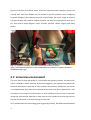
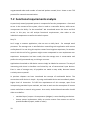
Last but not least VR is used in medical facilities, not only as an educational tool, but it
can also help to make diagnosis more accurate, perform robotic surgery and many
others.
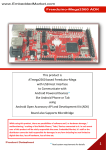
Img 2.1: Surgeon simulator used with Oculus Rift VR device, source:
[http://cdn2.digitalartsonline.co.uk/cmsdata/features/3457157/surgeon-simulator100045454-large.jpg]
2.2 Immersive environment
The term itself is often perceived in a connection with gaming industry and mainly VR,
which it extends in some measure. As the term suggests, user experiencing immersion
becomes absorbed in a partially, or fully synthetic environment. Sometimes the illusion
is so sophisticated, that after certain period of time user loses focus about what is real
and what is just immersive environment. In other words the success rate of particular
immersive environment depends on how much are we capable of convincing the user,
that the virtual scene he is experiencing is in fact real.
Let's proceed with the terminology given by gaming industry. We differentiate between
2
four basic categories of immersion:
•
Tactical – this kind of immersion occurs, when certain skill is required in order
to proceed. User feels to be drawn into the plot due to the ability to perform
and further develop this skill.
•
Strategic – immersion of this kind is apparent in situations, when the user is
obligated to make a decision. Game story is further developed based on this
choice.
•
Narrative – in order to ensure this immersion, it is necessary to create a
storyline. User participates in the story by trying to reveal the main plot. This
level of immersion is basically very similar to the feeling, that we have when
watching films or reading quality novels.
•
Spatial – it is a special kind of immersion, that relates closely to the subject of
this work. In this situation virtual environment makes such convincing effect,
that it appears to be real. To intensify the effect, we have the opportunity to
use various haptic devices, that allow us to enjoy the environment with more
human senses.
If we compare current state with a state a few years ago, we come to the conclusion,
that fantastic prophecies back then are slowly becoming real. One particular example
might be the device, known from the Star Trek: The Next Generation series, that
returned a sense of sight to the blind people. Israeli scientists came up with an
appliance called Sensory Substitution Device that collects visual information about the
surrounding environment due to its integrated camera. Acquired data are then
converted into sound waves with a help of complex algorithm and transferred into the
working hearing apparatus. It basically converts one human sense into another while
keeping the information value of the original perception. According to authors the
learning curve of Sensory Substitution Device is very steep and after short period of
time a blind person is not only able to recognize simple shapes, but reputedly also read
individual characters.
2.3 Stereoscopy
It's a case of technology, that allows us to fully benefit from the potential of human
vision – the ability to perceive depth. The input for such experience does not have to
be a real-world scene, two appropriately made images will be sufficient. From the
receiver's point of view, there are two main factors that are of our interest – monocular
3
and binocular keys.
2.3.1 Monocular keys
This mechanism allows us to use only single eye and raise the illusion of perceiving
depth. Among well known representatives there are:
2.3.1.1 Perspective
Linear perspective is a projection, which projects objects the bigger, the closer they are
to projection screen. Apart from that aerial perspective projects distant objects with
lowered color contrast, that is shifted towards blue tones. That is caused by the
scattering of light in atmosphere.
2.3.1.2 Accomodation
Accommodation relates to the change of optical power of the lens. As a result we are
capable of focusing on close and distant objects by turns. Therefore if we focus our
sight on close object within the distance of two metres, we experience the defocusing
of the objects placed farther. Analogically by focusing on a distant object, closer ones
will appear defocused.
2.3.1.3 Occlusion
As a term itself suggests, it controlls the visibility of objects, that are placed in different
distances. From the viewer's point of view, distant objects are partially or fully hidden
by the ones in smaller distance.
2.3.1.4 Peripheral vision
Human sense of sight allows us to view sharply objects, that are placed within the field
of view of approximately 45°. Peripherally we are capable of perceive objects within
the areas of 180°. These regions appear blurry and in addition the image is curved at
the angles near 180°. [2.2]
4
Img 2.2: Wide-angle lens is used to illustrate the curvature around edges, source:
[http://hqwide.com/wallpapers/l/1920x1200/71/usa_california_pavement_san_diego_
wide_angle_palms_1920x1200_70354.jpg]
2.3.2 Binocular keys
Apart from monocular, in case of binocular keys we are basically working with two
images collected at the same time from slightly shifted position.
2.3.2.1 Binocular disparity
Observed point projects itself on the retinal area. In the situation where two eyes are
present, two acquired projections might not be equal 1. The distance between
corresponding projections is called disparity. In case the projection on the left and the
right eye is equal2, it means, that perceived point is placed in so-called horopter, which
is a closed curve, connecting points of zero disparity.
Binocular disparity is enabled due to convergence. It is the ability to focus both eyes
into a single point. The observed point will be as a consequence projected into the
center of retina of both eyes.
1
2
In this case by equality we mean the equality of mirrored images.
Same situation as above.
5
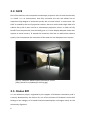
2.4 CAVE
One of the devices, that incorporate stereoscopic projection into its base functionality
is a CAVE. It is an environment, that fully surrounds the user and allows him to
experience high degree of immersion purely due to visual stimuli. In most cases, the
CAVE is created by the set of projection screens, that as a result create single sides of a
cuboid. Every side is then used as a stereoscopic projection screen. In order to fully
benefit from the potential, that the CAVE gives us, it must display adequate views with
respect to virtual scenery. To extend the immersion level we can add motion capture
system, that incorporates the movement of the observer into adequate scene repaint.
Img 2.3: Computer Aided Virtual Environment, source:
[http://www.iim.cz/updata/pic-69-2.bg.jpg]
2.5 Oculus Rift
It is an ambitious project, originated by the support of Kickstarter community and is
currently developed by the Oculus VR, one of the divisions of Facebook. Oculus Rift
belongs to the category of so-called head-mounted displays and targets mainly on the
community of gamers.
6
There are similar devices e.g. TDVisor, Recon Instruments HUD or Penny. But Oculus
Rift stands out of line with the level of immersion it can offer. One of these
characteristics is native support for stereoscopic projection. Images for left and right
eye do not overlap along the entire image. This apparent deficiency causes, that the
final image transferred to the brain is perceived as more believable, due to the fact,
that even images from human eyes do not perfectly overlap.
Another apparent advantage compared to similar devices is its field of view, which is
90° in horizontal and 110° in vertical direction. Thanks to this extent the whole area of
user's view is almost filled with virtual scene and the level of purely visual immersion is
therefore high.
In previous release, unleashed in 2012, Hillcrest Labs 3DoF head tracker was used.
Appart from the original version, the one used in Oculus Rift had used special
firmware, that made it run at 250Hz instead of 125Hz for standard version. 2014 Oculus
Rift has a build-in accelerometer, accelerometer and magnetometers. As a result of this
upgrade it is capable of tracking the head movement precisely againts the ground
without generating interfering drift.
Img 2.4: Oculus Rift VR device, source:
[http://blogs- mages.forbes.com/antonyleather/files/2014/04/OculusRift.jpg]
7
2.6 Multimodal device
Another option to enhance user's illusion of being present in real-world scene rather
than virtual one is to use multimodal device. The essence of such device is its ability to
work with five human senses in context of interaction with virtual environment. These
devices are divided into input and output. Input devices require the user to make some
action, while output devices arrange some kind of feedback to the user, that certain
action just occurred. From the user's point of view, input and output devices are
equally important. As the theme of this work suggests, we will primarily concentrate on
input aspects of multimodal device, but of course certain steps will be proposed in the
field of output. Apart from conventional controllers well known from consumer
electronics, multimodal controller is capable of working with speech, gestures or eye
movement.
8
3 Existing solutions
3.1 Simple UI Protocol
QNX company, that develops UNIX-based embedded systems, presented Simple UI
Protocol designated for the automotive industry. This protocol is capable of projecting
informative widgets from smartphone to Head-up display. Using another mobile device
allows us to monitor current interior temperature and display A/C settings including
control UI. In order to quickly set the whole system up, bluetooth is used as a transport
layer. Unfortunately API is available only within OEM licence and so-called Tier 1
customers.
3.2 Apple accessory protocol
This protocol is used as a standardized interface for Apple products. Due to this
solution, devices are capable of communication with e.g. docking stations. This
protocol is an example of a system, that on one hand is able to propagate metadata to
other platforms, on the other hand the UI on target devices is always the same, and
there is no way how to customize displayed widgets.
3.3 Verse
Verse is network protocol, that allows graphic applications to communicate with each
other in real time. Using this approach, an artist, working in Blender, can work on the
model of building, which is at the same time being constructed using CAD software.
Designers of Verse are aware of the fact, that the amount of information being
transmitted by graphic applications can be excessive. For this reason, applications do
not communicate directly, but rather via cloud, that performs necessary optimization.
Not only is Verse capable of synchronizing graphic editors, but due to its scalability it is
possible to integrate it into custom projects, like gaming industry or visualization. Verse
is considered successful tool, but due to its complexity cannot be categorized as simple
protocol.
9
3.4 Android as a gaming controller
For now, we will step aside from the list of protocols in general and introduce an
Android application, that is used to control PlayStation 3 gaming console. PS is by
default equipped with DualShock controller. Despite the fact, that the controller is very
popular among the community of gamers, it has one noticeable weakness - text input.
By obtaining hardware keyboard we partially solve this issue, but it requires another
expenses and another device we have to take care of. As a free alternative we can use
the BlueputDroid application, available on the Google Play 3. Due to features of this
application, we can now simulate the Dual Shock controller on Android device, while
keeping the benefits of Android software keyboard. Furthermore, drawing canvas is
optionally displayed in order to define simple shapes with touch input. BlueputDroid
can also be used with PC and substitute mouse or keyboard. The ability to remotely
controlled target system is allowed due to usage of bluetooth.
3
10
https://play.google.com/store/apps/details?id=berserker.android.apps.blueputdroidpro
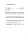
4 Problem specification
Img 4.1: Initial problem
The initial problem is illustrated on the image above [4.1]. VR system is comprised of
VR device itself and respective controller application. Our task is to use the VR system’s
control interface and connect it with Android device. There are problems, we have to
deal with:
1. There is no such thing as standardized control interface of VR systems. It is even
not possible to force such standardization procedure, because almost every
device needs specific input. Therefore we will have to come up with the idea of
creating universal adapter (note: design pattern), that is capable of
communicating with VR system as well as Android device.
2. How to display all these different control panels on a single Android device?
There is of course a possibility to make different layouts to all the VR systems,
that particular device controls. But what about new devices, that can be used as
controllers as well? Are those devices capable of controlling the system at the
same time? What about the mutual synchronization?
3. In case there are really multiple layouts present on single controller device,
there must also be present underlying event - listener logic, that will map user
actions to control inputs on the serving adapter. Again, the question of
portability arises.
As a result of this approach, we will have to write a lot of repetitive code in order to get
the controller working. All the previously difficulties would have to be solved for every
newly supported control interface.
With previous approach in mind let’s discuss the solution, which is in fact a part of
official guidelines regarding this work.
To define the term Remote UI we have to assume two sides of the system. Let’s label
11
them client and server. Server is used as a single entity, that includes all the
information necessary to display UI. Client is a device, which eventually displays UI
defined on server side. UI we are currently talking about is in fact remote UI. We call it
remote, because:
1. UI is only displayed on client side, the definition came from server side.
2. All event handlers are located on server side and are therefore called remotely.
Why are we introducing such complicated concept? Because it is a solution to
previously listed obstacles, that arised from the definition of separate layouts for
separate VR systems. We will compare both concepts, but for the sake of clarity, let us
call the previous approach UI_1.0 and the concept of remote UI simply RUI.
Both UI_1.0 and RUI consist of server (possibly containing adapter) and client. Server
and client communicate over network using certain protocol.
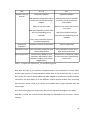
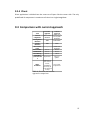
12
Task
UI_1.0
RUI
Support new VR
devices
implement adapter
implement adapter
add required control methods on
server side and link them with
adapter
add required control methods
on server side and link them
with adapter
define UI on client side
define UI on server side and set
it on client
add event listeners and link them
with corresponding server
add event handlers and link
methods
them with corresponding server
methods
every client controller must be
reinstaled separately
Synchronize
controllers
implement custom functionality
Portability issues every controller needs the most
current APK version
New components
created once; added to each
controller individually, either
directly in code or as a part of
widget library
natively supported
every controller has the same
APK version at all times
created once; if required, added
to each controller automatically
from server
Table 1: Comparison between UI_1.0 and RUI approach
Now that we have UI_1.0 and RUI compared what is the conclusion? In both cases,
almost equal portion of implementation would have to be performed. But in case of
RUI, we do not concern about additional code needed to synchronize possibly multiple
controllers. RUI also allows us to use different control layouts without even restarting
the controller device, while UI_1.0 forces us to update every single controller with the
current APK.
As a result of the previous comparison, we use RUI approach throughout this work.
With RUI in mind, we need to further develop the foundations of our Client - Server
concept.
13
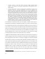
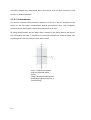
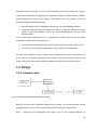
4.1 Client – server approach
In further parts of this work we will be using terms, that come from scientific area
called Controll theory. Key elements, that relate closely to our work are System and
Controller [4.2].
System is an individual entity, that provides certain output, service, or monitors
particular event. The fundamental feature of the server is its ability to be controlled
and for this reason it offers control interface. Server, that does not allow to be
controlled is called passive and will not be subject of further research. Apart from that,
dynamic server can be further customized and by affecting input values we can
manipulate its output.
Img 4.2: Basic entities of Control theory
Apart from that, controller is a device, that is capable of controlling the system. From
the general perspective, control interface is known in advance. For the sake of
simplicity now we ignore the fact, that the control interface is unknown for the remote
UI controller.
At first, we will discuss available interaction scenarios:
•
System > User
◦ Scenario, that is well known from desktop computing. User communicates
directly with system using some kind of integrated interface (probably
mouse or keyboard with conjunction with application user interface).
System responds either directly (system API call) or undirectly using web
14
service, cloud, ...
•
System > System
◦ Applications on single device – Certain synchronization services belong to
this category. For example “away” state of office communicator is displayed,
when the person's calendar contains an appointment in certain hour.
Applications therefore need to define communication interface, in this case
events synchronization.
◦ Applications on multiple devices – Glowing example is multiplayer game.
Devices are configured to use certain network resources and
communication protocol.
•
System > Controller
◦ In this case a fully-fledged controller is used as an input / output device to
some more complicated system. In our case, the system is represented by
VR system and Android-based device is used as a controller.
4.1.1 Multiple entities issue
So far, we ignored two important facts. For one thing, there are situations, where
either side of the system is represented by more than one device. For another, we
cannot neglect the activity degree of either controller or server. For the sake of clarity,
we will earmark two basic categories:
•
degree of activity
•
multiplicity
4.1.1.1 Degree of activity
Determines to what degree particular entity is active when it comes to communicating
with the other side, we therefore distinguish:
•
server passive, client active - client holds the role of a controller, every action
performed on client device is apparent on the target system only
•
server active, client passive - in this case client is used as a monitoring device
only
•
server active, client active - approach, that will be further used throughout this
work. On the one hand client controller affects the state of target application.
On the other hand, monitoring features can be part of client device as well. This
approach is used in case of controllers of advanced flight simulators. While user
controlls the aircraft using joystick, flight-related informations are displayed on
a small screen placed within the docking station of the joystick.
•
Defines the number of devices within each side of the proposed system
15
•
1 server, 1 client - In this case, server has only a single controller device
assigned. The example of such unary relationship can be television and its
remote control.
•
1 server, many clients - Server is simultaneously controlled by multiple client
controllers. There are real-world applications, that use this approach e.g.
various instructional applications, where student is under supervision of a
teacher and by using another controller teacher can avoid dangerous situations
to originate. Multiplicity of one server and many clients will be across this work.
•
More than 1 server, many clients - In this case, server is represented by multiple
devices and they are all controlled by 1 to many clients. As a simple use-case we
can imagine a conference room with a big round table with chairs around.
There is a monitor and a corresponding controller placed against every chair. If
a presentation takes place in such room, presenters may alternate without
changing seating. In order to ensure the quality output of such meeting all
servers as well as all client controllers must be synchronized.4
As a motivation to synchronize clients, we can imagine a situation, where server is
simultaneously controlled by smartphone and tablet. Let’s assume, that both devices
are Android-based with client controller application installed and running. Controller UI
is very simple, it consists of three two regular and three radio buttons, that are placed
within one radio group, in order to ensure the condition, that at most one radio button
at a time, can be selected. If we now select one of the buttons on smartphone, it will
activate adequate action on server side, but the tablet’s UI stays without any change
and therefore does not reflect current state of the server / controller.
I suggest the solution based on model, that reflects the current state of controller. In
case any change on client device is detected, this information will be propagated to the
server along with the event itself. It is necessary to engage server, because individual
controller does not have any clue about other potentially connected controllers. As a
result, special event called reverse update is generated and sent to all controllers. Due
to this feature, the state of all clients is updated and therefore the same. By using this
approach we need to ensure, that there is only one instance of model across the
suggested system. In order to comply with this condition, we place the singleton of
model on the server. Now, due to the fact, that server keeps track of connected
controllers, whenever any change of state occurs, enforcing client devices to update
4
16
Situation, where multiple target applications share a controller is not within the scope of this work.
their states is a matter of single reverse update.
We should point out, that not every situation requires controllers to synchronize. It is
determined by the UI elements used. In case there are only simple buttons, there is no
need to synchronize such device, because the state differs only at the moment when
button is pressed. As a result, state of all controllers is natively synchronized and a
small inconsistence of currently pressed button can be tolerated.
17
18
5 Android platform
Since the beginning of Android platform, it has always had a broad community of
developers. One of the reasons of this success is its open source nature. At the time of
writing this work, there are two preffered development IDEs, that have already been
pre-configured to be used out of the box.
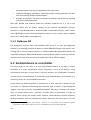
5.1 Development options
5.1.1 ADT Bundle
This development tool is built upon popular open source IDE Eclipse. Programmers,
used to either standard or enterprise edition have the option to download ADT plugin,
thereby having the same tools as in ADT Bundle. Due to fact, that ADT Bundle exists
since November 2009, certainly long time passed since the first release and therefore
its existence has proved as useful. Apart from standard features, ADT Bundle offers:
•
Android-specific refactoring and quick fixes
•
allows to monitor the load of connected device, background applications and
hardware devices
•
clearly arranged UI editor, advances tools, that make the process of UI tweaking
much easier
•
advanced debugging tools, informing about current CPU / GPU load
•
ability to compile and package existing sources written in C/C++
•
opportunity to run applications on advanced virtual device, that allows to
simulate camera, sensors, multitouch or telephony
5.1.2 Android Studio
In June 2013 a new version of development environment was released named Android
Studio. It is built upon community edition of IntelliJ IDEA. Just as ADT Bundle, Android
Studio is open source project as well. Proven IntelliJ functionality is enriched by tool,
specifically designed to facilitate Android development, ie.
•
Refactoring tools and quick fixes, specific for Android platform
•
UI designer, offering drag & drop definition of new UI elements, multiple screen
19
preview without restarting the application and many more
•
Improved debugging capabilities, advanced profiler, simple generation of UNIT
tests and mocking Android-related objects
•
Number of templates, that ease the process of making routine tasks or creating
commonly used components
Both ADT Bundle and Android Studio are officially supported so it is up to the
developer, which one to choose. Google so far invested considerable financial
resources in the development of Android Studio. Compared to Eclipse, IntelliJ seems
more lightweight and the whole development process is more natural, when updated
syntax tree5 always offers meaningful hint.
5.1.3 Netbeans IDE
For developers used to work with Netbeans IDE, there is no such pre-configured
solution. It is although possible to obtain so-called NBAndroid plugin and install it into
existing IDE. In case of smaller projects, an unskilled developer appreciates mainly the
simplified workspace. Advanced developers would probably switch to one of previously
mentioned solutions due to number of handy tools and an official support.
5.2 Android device as a controller
The main target of this work is to use Android-based device as an input / output
controller of a more complicated system. Especially in case of VR devices, using
conventional controllers in most cases is not very intuitive, nor comfortable. Therefore
we will discuss the possibilities of interaction using Android device and whether it is
necessary to rely only on provided functionality.
Device based on Android platform is attractive to us from two main reasons. On the
one hand it is capable of displaying User Interface with a number of pre-configured
widgets, that can be further extended(customized). Whenever situation like button
click, or canvas touch occurs, particular so-called event is generated. In order to
controll these events, we employ event listeners, which basically contain necessary
callback methods, that are automatically called, whenever the event occurs. On the
5
20
Apart from Eclipse, IntelliJ „feels context, “ stará se o to, aby syntax tree byl aktuální a pokud
programátor zvolí možnost quick fixu, pak je mu nabídnuta pouze relevantní nápověda.
other hand, there is a wide variety of hardware sensors available on Android devices.
These sensors and their potential usage will be further discussed throughout this
chapter.
5.2.1 UI events
User interface serves in general two major functions:
•
displays the current application state
•
allows to alter the application state by pre-defined interaction
5.2.1.1 Display of current application state
There are applications, that serve only one pre-programmed purpose – e.g. displaying
current air conditions. In this simplified example, no user input is required, therefore
application itself can be referred as a passive.
5.2.1.2 User interface interaction
Let's inspect the concept of events and listeners a little bit deeper. Try to imagine a
simple button, on Android platform realized by widget android.widget.Button. By
instantiating class, that implements interface android.view.View.OnClickListener we
now have a handler, that needs to be registered as a listener to our simple button. If
we now press the button, onClick(View v) method is called in our instance of
OnClickListener and allows us to respond to this event accordingly.
In practice, we do not need to rely on using only simple buttons and listeners, that
handle click events. Real-world applications use more sophisticated widgets, that can
have number of custom listeners assigned to them. Numerous examples are painting
canvas in editor of 2D graphics, matrix of cells in spreadsheet processor or multiselect
component in enterprise web application.
5.2.2 Sensor events
Most Android-based devices feature a range of various sensors, that can be
incorporated when transforming such device into a controller. Therefore information
regarding position, relation to surrounding environment or motion can put the ordinary
21
controller towards the multimodal. Here we present a list of most commonly used
sensors on Android platform.
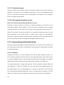
5.2.2.1 Accelerometer
This sensor measures the acceleration applied to a device. If we for example put the
device on the flat table, accelerometer detects gravitational force, that constantly
pushes onto the device with a value of approximately 9.81 m/s2.
By using accelerometer we can obtain Euler rotation of the whole device and due to
this information we have a possibility to control for example the model of space ship
according to the current rotation of the device itself.
Img 5.1: Default coordinate
system of Android device,
source:
[(http://developer.android.com/
guide/topics/sensors/sensors_o
verview.html)]
22
5.2.2.2 Gravity sensor
The output of this sensor is a three dimensional vector, containing direction and
magnitude of gravity. Coordinate system is the same as with accelerometer. Every user
of Android device already benefits from this piece of hardware. Due to this sensor,
applications detect the change of orientation and switch from portrait to landscape
and vice versa.
5.2.2.3 Gyroscope
This device is particularly useful, when measuring the rate of device's rotation around
the particular axis. Rotation is registered as positive, when the direction of such
movement happens in counter-clockwise manner. Coordinate system stays the same as
in case of accelerometer.
5.2.2.4 Linear accelerometer
Three-dimensional vector of acceleration is obtained for each axis as well as in case of
previously described accelerometer. The only thing that vary is, that linear
accelerometer does not take into account the gravitation force, so device layed on the
flat surface will have acceleration of 0 in each axis.
5.2.2.5 Geomagnetic field sensor
This sensor is used to monitor changes in geomagnetic field of Earth. We will probably
not access the obtained information directly. But in a combination with rotation sensor
vector we are capable of computing rotation and inclination matrix. These matrices are
commonly used as input parameters of getOrientation() and getInclination methods in
order to get the azimuth and geomagnetic inclination data.
5.2.2.6 Proximity sensor
Thanks to this sensor we can obtain the distance to the nearest object in device's
surroundings. Majority of today's Android devices is capable of returning the absolute
distance.
23
5.2.2.7 Orientation sensor
Using this sensor we can obtain device's orientation relative to the earth's frame of
reference. This sensor is not a hardware component. In this case geomagnetic field
sensor is used with conjunction with accelerometer. The output of such synthetic
sensor is azimuth, pitch and roll.
5.2.2.8 Note regarding hardware events
More controllers generating hardware events
Knowing the basic overview of sensors on Android platform we now face on an
interesting problem. What happens if we use sensoric information from multiple
controller devices at the same time? Sensors usually generate events every 50 –
100ms. That means, that every second 20 – 40 mutually inconsistent events are sent
from controllers to the server device. In special cases, where this extraordinary
behaviour is required, devices should be given unique IDs. These IDs should be then
sent as a part of sensor event message to distinguish respective devices.
5.2.3 Incorporating multimodal device
Having the overall knowledge of using Android device as an event-driven controller, we
can now present several steps, that allow the final controller to comply with a concept
of multimodal device.
5.2.3.1 Gestures
Sometimes the device is used in situations far from the ideal. People are often in a
hurry and they simply cannot fully focus on pressing small button, which allows them
to e.g. start workout activity. If we substitute the small button for bigger one, problem
might not be solved and we even loose more precious space in current layout.
I see better approach in using touch gestures. For this purpose, Android offers API
android.gesture. It offers the interface to save, load, draw and recognize gestures. If
the target platform, we are developing for, is version 1.6 and above, we can benefit
from using Gestures Builder application, which is a default part of emulator. This tool
allows us to create custom set of gestures, that can later be used in our applications.
24
Apart from touch gestures, that were previously described, we can create custom
gestures, that incorporate the movement of the device itself. By using accelerometer,
gyroscope, or any other sensor available for Android platform, we can achieve the
behaviour of our own. Unfortunately, in this case we cannot take the advantage of
existing API, but we have to develop it from scratch.
To finish the part dedicated to gestures, there is one golden rule, that should always be
applied. We should not overuse gestures, because user may easily get confused by
excessive number of complex gestures.
5.2.3.2 Haptic feedback
There is another way how to let the user know, that the particular event has just
occurred. For this situation we will choose haptic feedback, namely vibrations. API
provides abstract class android.os.Vibrator. To obtain particular instance, we have to
have access to application Context and use the following:
In order to start vibrations, all we have to do is call the following method
which will basically let the device vibrate for 50ms.
In special cases, when simple vibrations are not enough, overloaded variant of vibrate
method will suit our needs. Simple pattern is used in order to specify intervals of
individual vibrations:
Haptic feedback should be used especially in cases when user's attention is distracted
25
by other factors and visual notification is not applicable. Same rule as in case of
gestures applies, because user quickly adopts this form of output.
26
27
6 Requirements
We reached the point where certain features from previous chapters need to be
summarized into the set of functional and non-functional requirements. These apply
for the proposed system. Requirements are further analyzed in the subsequent
chapter.
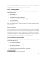
6.1 Non-functional requirements
Before we proceeded to the design of the future system, we defined a set of nonfunctional requirements used to define the operation of the system.
Req N.1
Accessibility
Req N.2
Extensibility
Req N.3
Performance
Req N.4
Responsive / responsiveness
Req N.5
Portability
Req N.6
Response time
Req N.7
Usability
Req N.8
Networking
6.2 Functional requirements
In contrast to non-functional requirements, functional requirements define specific
behaviour and functions that should finish system incorporate.
Req F.1
Ability to controll systems, especially VR applications
Req F.2
Platform independent communication protocol
Req F.3
Possibility to define remote UI via XML configuration file
Req F.4
Possibility to define custom components
Req F.5
Option to add support for new sensors
Req F.6
Support for more controllers
Req F.7
Simple way of pairing controller with system
Req F.8
Simple way of incorporation “the ability to be controlled” into legacy
application
28
Req F.9
29
Ability to dynamically change attributes of UI components
7 Requirements analysis and design
This chapter concentrates on detailed analysis of brief requirements from the previous
chapter. Furthermore, design of proposed system is presented, where concrete aspects
of client and server side are further developed.
7.1 Non-functional requirements analysis
Req N.1
Result of this work should be accessible to a wide variety of users. Our task is to make
this accessibility possible. By integrating the core aspects of multimodal controller,
resulting system will be capable of offering user interfaces, that take the advantage of
multiple human senses.
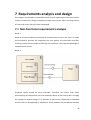
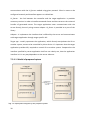
Req N.2
Img 7.1: Basic principle of modular approach
Proposed system should be easily extended. Therefore, we cannot think about
accompanying all components into one monolithic block. All we need to do is to apply
the concept of modular design [7.1]. Modules in general are understood as individual
entities, that can be deployed as standalone. These modules use pre-defined interface
30
to communicate with other modules. Let’s introduce another term, that in fact
represents a subset of module called plugin. Plugins can be viewed as smaller modules,
that extend the functionality of an existing system. Simple plugin architecture is
displayed on following diagram.
1. Core - Core system provides necessary services, that can be used by plugins. It
manages installed plugins and is able to operate completely independent of
installed plugins.
2. Plugins - Using API, provided by core system, plugins may register themselves in
order to provide and/or receive data from other plugins or core system itself. It
is usually not possible to use plugins independently of the core system.
Req N.3
According to the fact, that substantial part of this work is applied to user interface, it is
necessary to ensure minimum latency and fast response times. In order to satisfy this
condition, we incorporate the logic, that controls the visual appearance and rendering
of UI components into the client device.
Req N.4
We will be using concept, that is applied also as a part of Web 2.0 specification.
Proposed system should be capable of displaying the controller’s UI on wide range of
devices with various screen dimensions. By using native set of Android platform
widgets it is guaranteed, that rendered components are drawn proportionally to the
device’s screen.
Req N.5
Resulting client application is deployable on all Android devices versioned 4.0 and
above. APK itself is by its nature portable to any other supported version of Android
platform.
Req N.6
This requirement is closely related to Req N.3. When it comes to UI, increased latency
may confuse the user and finally discourage him to work with such user interface. Since
the user expects the feedback of his action to be immediate, it is necessary to
31
guarantee minimum latency.6
Req N.7
Application setup should be simple to use. Time, needed to be spent upon user manual
should therefore be minimized. The general philosophy of the system therefore is to be
immediately ready to use with minimum required configuration.
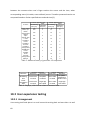
Req N.8
If we concentrate on currently used Android devices, we have basically two ways how
to wirelessly communicate. We can use either Wi-Fi or bluetooth. When determining
appropriate method, we have to take into account the target system. In our case this
system equals to VR application, that run on PC, notebook, or even powerful server(s).
These devices are in majority of cases connected to network, either via wired or
wireless network. Unfortunately this assumption can’t be made in case of bluetooth
adapter.
Specification
Version
Frequency
Data transfer
Range
Max. number of devices
Security
Power consumption
Wifi
802.11.a, b, g, n
2.4 GHz, 3.6 GHz, 5 GHz
250Mbps (802.11.n)
100+m
According to router specification
Key matching
high
Bluetooth
2.0, 2.1, 3.0, 4.0
2.4 GHz
25Mbps (4.0)
30m
<=7
WEP, WPA, WPA2
low
Table 2: Wifi and Bluetooth comparison
According to previously stated and table [2], I’ve decided to use Wifi to transmit and
receive all network communication.
Knowing we will be using computer network, there is another decision to be made. We
can send messages upon Transmission Control Protocol (TCP) or User Datagram
Protocol (UDP).
Despite the fact, that UDP is faster, its lack of error-checking mechanism and
6 Approximately 50ms is generally considered the upper bound.
32
unguaranteed order and number of received packets caused, that I chose to use TCP
protocol for network communication.
7.2 Functional requirements analysis
As previously stated, proposed system is composed of two key components - client and
server. In the context of the system, client is used as a controller device, while server
incorporates the ability “to be controlled.” We introduced terms RUI client and RUI
server. In this part, we will analyze functional requirements, that relate to the
individual components as well as the whole system
Req F.1
Let’s image a common application, that we use on daily basis - for example word
processor. The average user is satisfied when controlling such application with mouse
and keyboard. For one thing this opinion comes from longtime experience, for another
control with the aid of e.g. gestures might cause unexpected or even unpleasant user
experience. Assumption has been made, that the average user is conservative and
prefers the old, protracted way, to risking a new one.
Applications launched on VR device cannot simply be labeled as common. The way of
interacting with them is therefore not limited by use of conventional input devices.
Even in case of average user, all prejudice are made to step aside, because human
curiosity starts to prevail.
In previous chapters we have introduced the concept of multimodal device. The
connection to VR device is simple - by using multimodal device we immediately obtain
higher level of immersion. To fulfill the requirements of this concept, apart from
incorporating standard input methods, we have to work on the assumption of human
nature and allow to control using senses. As a result, Android-based controller should
allow us to define:
33
•
standard input / output: UI components (widgets) + event handling mechanism
•
human senses involvement: ability to receive events from sensors as well as
provide feedback (haptic, audio or other)
Req F.2
VR systems and other target applications are built upon various platforms. Therefore,
proposed system have to comply with (two) key criteria:
•
platform independent protocol
•
implementation independent protocol
As we previously stated, all communication is built upon TCP/IP. However we did not
specify the format of those messages. In order to comply with implementation
independence, we have basically two options - XML and JSON.
XML
Pros:
•
human readable
•
position independent
•
extensibility
•
flexibility
Cons:
•
heavyweight parsers
•
repetition of tags
JSON
Pros:
•
lightweight
•
easily readable
•
data-interchangeability
Cons:
•
not as heavily used as XML
•
absence of namespaces
•
absence of grammar
34
Despite the fact, that JSON excels as a data-interchange format, XML is used. The main
reason is the overall consistency of the proposed system - XML will be used in case of
configuration and layout-definition files. According to requirements, communication
will not be encrypted.
Speaking of XML, there is a possibility to marshall and unmarshall POJOs 7 on client and
server side with a little aid from well-known frameworks, e.g. JAXB, JiBX or Simple.
While neither have native support on Android platform, it is strongly recommended to
use either JiBX or Simple, because JAXB has a large footprint (ca. 9MB). Unfortunately
the output of these automated tools is usually not platform independent and therefore
would need to be further processed by XSLT, DOM, or other technology.
Req F.3
Preferred way of creating UI for Android is by XML definition. To stay consistent with
this approach, we apply the same pattern, when defining UI for client controller. All
layouts defined as XML files must be known before the compilation phase which is in
fact the biggest obstacle, that we have to deal with. In future Android releases, there
might be possible to define alter UI using external XML, but for now it is not possible 8.
By applying programmatic approach, we do not have such limitation. It is possible to
create instance of concrete UI component using Simple factory, because all UI
components have supertype - View) and place it within existing layout.
I decided to combine both approaches. Using XML notation makes the development of
UI components easier and enforces separation of view layer from application logic. One
drawback resulting from this approach, is the need of unmarshalling XML in each
module.
Req F.4
Try to imagine following situation: there is a certain number of components being used
on particular controller. This controller is then deployed to several client devices. If we
change the definition of one device’s component, we bring inconsistency into the
7
8
35
Plain Old Java Object
As thoroughly stated in http://developer.android.com/reference/android/view/LayoutInflater.html
system. This may lead to unpredictable behaviour or even crash the system.
We therefore need a different approach. Client device must be thought of as “finished”
application that shouldn’t be altered and further recompiled. All UI components and
other extensions will be installed as separate modules. There must be certain
mechanism, that forces all devices to use the most current module definition. To satisfy
this principle, we need to determine two things:
•
interface, that all modules must implement
•
how to remotely install module into client application
In the design part of this work, interface for new modules will be further discussed.
The process of installing new modules into client device is inspired by Apache Maven.
In order to obtain the required version of artifact, Maven searches its repository and
downloads its content to specified location on filesystem. In our case, there is no need
to download specific version of module. Our requirement is to download the latest
one, so that all client devices use the same module.
As a storage for all available modules, any publicly available server, that supports Direct
download, will be used. In order to download a particular module, the only thing
needed is URL. Server application keeps track of available modules and provides the
necessary URLs to client device.
Req F.5
In case of sensors, we use a different approach than when dealing with UI components.
To access particular sensor, we need getSystemService(SENSOR_SERVICE) method,
which is defined in abstract class android.content.Context. If module can access current
application Context, then it is possible to collect information from particular sensor. In
case there is a new hardware sensor available, all we need to do, is to save particular
module into repository and let client download it.
Req F.6
The only limiting factor is router, that allows devices to wirelessly communicate. We
can assume, that in real-time application the number of concurrent controllers will be
36
smaller than ten.
As previously discussed, in case of more than one controller in the proposed system we
have to synchronize these devices, by applying the reverse update principle into the
server logic.
Req F.7
Since, in view of the fact that all communication between server and client will be
handled over network, there are two necessary information, that needs to be provided
in order to facilitate the connection:
1. Both server and client side must run within the same network. Client device
uses wifi, while server has no such limitation. In order to guarantee the visibility
of both sides, it is recommended to check router settings.
2. Client application needs the IP address and port number in order to successfully
connect to server. It is not guaranteed, that server is given the same IP address
and port number at all times. Therefore when any client device is run, simple
input is provided in order to be filled with current server details.
Req F.8
“To be controlled” is a feature, that we demand from newly developed applications, as
well as the legacy ones. Therefore proposed system needs to provide clearly defined
API.
One of the key features of the proposed system is, that its integration into existing
application is possible without interfering with its architecture. The ideal scenario
would be as follows:
•
add RUI library on classpath of target application
•
configure remote UI using XML layout file
•
implement adapter, that from one side is connected on control API of target
application and from the other side provides mapping to RUI functionality
Req F.9
This requirement is very closely related to the problematics of previously stated reverse
update.
The main motivation in this case is to reflect the state of target application on a
37
controller device. In order to ensure such behaviour we need to alter the value of
component’s attribute. By applying this approach we get a certain level of comfort
when dealing with custom state values. Let’s explore how the change of state is
achieved using standard Android API:
1. We obtain particular UI component reference, e.g. android.widget.Button.
2. Using the reference we call component’s setter in order to reflect the current
state. In case of a Button, using e.g. setText(CharSequence) we can alter
Button’s label.
We can use similar approach, but it is important to realize, that we cannot obtain
component’s reference directly, because:
1. UI component is placed on client device, while we are accessing it from server
2. There are as many equal components, as the number of client devices
Therefore we introduce a proxy object, that encapsulates the state of controller on
server side. It is by design guaranteed, that there is only one controller proxy on the
server. Finally, this proxy object needs to update the state of all connected clients.
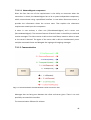
7.3 Design
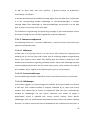
7.3.1 Common view
Img 7.2: General scheme of the proposed system
Here[7.2] we can see a simplified diagram of the system. The communication is quite
straightforward, so let's move on to the roles of each particular component.
Client - represents the application itself, which runs on the Android platform. It
38
communicates with the UI_Server module using given protocol. Client is meant to be
configured remotely and therefore appears as a black-box.
UI_Server - the link between the controller and the target application. It provides
necessary services in order to handle connected clients and also serves as the universal
handler of generated events. The target application never communicates with the
server directly, but only using custom adapter. UI_Server is provided as a part of the
library
Adapter - it implements the interface that is offered by the server and communicates
with target application through target specific API
Target app - usually represents the application, which directly manipulates the VR or
another system, meant to be controlled by client device. It’s important that the target
application provides API, required to control VR or another system. Compared to the
interface specified by server application itself we can clearly see, that the application
interface isn’t in any way dependent on the server side one.
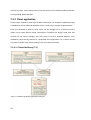
7.3.1.1 Model of proposed system
Img 7.3: Deployment diagram of the proposed system
39
7.3.1.1.1 NetworkAgent component
Given the fact that one of the requirements is the ability to reconnect when the
connection is closed, the NetworkAgent has to be a system-independent component,
which communicates using a predefined interface. In case when disconnect occurs, it
provides the information about the current state. That explains the robustness
requirement stated upon this component.
It exists in two versions, a client one (ClientNetworkAgent) and a server one
(ServerNetworkAgent). The common feature of both of them is the ability to send and
receive messages. The client version is able to shut itself down, based on either its own
or the server’s demand. The agent of the server side is able to simultaneously serve
multiple connected clients and delegate the ingoing and outgoing messages.
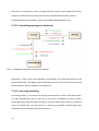
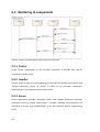
7.3.1.2 Communication
Img 7.4: Communication schema between client and server side
Messages that are being sent between the client and server given. There is no such
possibility to extend this interface.
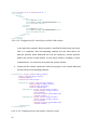
The communication follows this scheme:
40
1. InitRequest: Client device asks to initialize the connection. It sends a request to
the server, containing device identification and information regarding installed
components along with their version numbers.
•
Server accepts or denies the connection. In both cases it responds and
sends an appropriate flag. In case the connection attempt was successful it
also provides a list of components that have to be downloaded. Finally,
client is added into the list of connected devices.
2. UIRequest: When the client finishes downloading the required components, it
sends a request for the default UI layout to the server.
•
Server responds with the default layout definition. When the layout is
properly set, client may receive additional messages, that force individual UI
components to update their state in order to reflect current application
state.
3. EventOccured: Each time the client device generates an event, it is sent to the
server.
•
Server dispatches received event further to the adapter, that additionally
launches particular action on target application. There’s a possibility that
the event caused a change widget’s state. In that particular case the server
broadcasts a reverse update message in order to re-render the affected
widget on all connected clients.
4. ForceUIUpdate: A message of this type is sent in two cases:
•
As a part of a reverse update, in which case its purpose is to synchronize all
the client devices (PropagateUIUpdate)
•
As a request of the target application. There may be situation, when
adapter requires to change the attribute of particular component
(ForceUIUpdate)
5. DisconnectRequest: A client requests to terminate the connection.
•
Server confirms disconnecting the client and finally removes the client from
the list of connected devices.
6. ForceDisconnect: The server forces the client to disconnect. After the client is
disconnected the server removes it from the list of connected devices.
All the communication is carried out using so called message objects. In order to sent
these objects over the network using NetworkAgent, it’s necessary to serialize
(marshall) them into XML format.
A so called Dispatcher is used on the application logic layer to control the
communication. Dispatcher is present on both client and server side, but either server
41
as well as client have their own specifics. A general process of Dispatcher’s
functionality is as follows:
It accepts deserialized (unmarshalled) message object from the XML layer and provides
it to the corresponding handler (UIManager or ConnectionManager). It accepts
message object from UIManager or ConnectionManager and provide it to the XML
layer so that it can be sent to the other side.
The mechanism of generating and processing messages is given and therefore cannot
be altered. Though we are still able to guarantee required modularity.
7.3.1.3 Common components
The following classes are - in certain modifications - present on both client and server
side of the proposed system.
7.3.1.3.1 UIManager
It takes care of all the logic which is, on the server side, focused on composing and
updating the UI. On the client side it takes care of rendering widgets and generating
events, that relate to them. Apart from dealing with the visible UI elements it also
handles all the interaction regarding hardware sensors. Server side UIManager handles
reverse updates and interacts with the client layout proxy. It also contains the stack of
all UI updates, which, applied to the default layout, gives us current layout.
7.3.1.3.2 ConnectionManager
ConnectionManager handles initialization of the connection as well as its termination.
7.3.1.3.3 JARManager
As the name suggests, this class manages the modules, that are provided in the format
of JAR files. Each installed module is uniquely identified by its name and version
number. Each module has its record in configuration XML file, that is automatically
handled by JARManager. For this reason, whenever new version of plugin is
downloaded, record is updated with current version number. Client specific
JARManager does not automatically download the latest version of module available
because it is used to receive the order to download certain module from the server. In
42
contrast to client, server keeps track of current versions of available modules and their
corresponding download URLs.
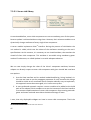
7.3.2 Client application
Client can be viewed as View layer of MVC architecture. All respective application logic
is handled on server side and therefore client is used only in context of presentation.
From the developer’s point of view, client can be thought of as a black-box and is
meant to be used without being recompiled. Therefore the design must take into
account all the future changes, that may occur in case of Android platform. Also,
modularity stays the key feature of a proposed client application. As a result, we not
only have to make client robust enough, but also easily extensible.
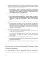
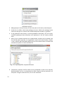
7.3.2.1 Client-side library [7.5]
Img 7.5: Content of library guiproject-client.jar
43
The modularity of the client device is achieved on two levels. For one we have the
ability to define new UI components by implementing a View interface. If we want to
use new hardware sensors, then we have to implement an Activity interface.
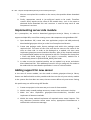
Img 7.6: Part of Android View hierarchy, source: [http://www.itcsolutions.eu/wpcontent/uploads/2011/08/Part_of__Android_View_Hierarchy.png]
interface is similar to the Android platform, specifically the android.view.View class. As
picture 7.6 illustrates, it is obvious, that View is not only parent class to all UI
components, but also figures as parent class to all layout managers (on Android
platform child classes of android.view.ViewGroup). By applying the similar approach we
can also create general View interface implemented by all modules. We can see that
the return type of the method getView(Attributes) is android.view.View. After all
required attributes are set appropriate Android View object is returned and can be
programmatically added into current layout
44
Apart from UI components, there is always only one instance, that implements Activity
interface and therefore all required sensors must be defined within this instance.
Creating specific client module is further described in documentation part.
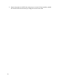
7.3.2.2 Dispatching messages on client side
Img 7.7: Delegating messages to respective handlers
Dispatcher in case of the client application has basically the same functionality as the
general Dispatcher. The diagram above illustrates how the client side initiates both the
communication and the request for the default UI.
7.3.2.3 User input validation
According to Req F.7, the process of pairing client and server device should be simple.
The only required user input in this case is the server’s IP address and port number.
These data have to be provided manually by the user, which means there is a potential
risk of an invalid input. For this reason it is necessary to validate corresponding input
fields before received data are further processed.
45
Img 7.8: Structures used during validation phase
On the diagram [7.8] we can see the structures used in the process of validation. An
OnFocusChangeListener is attached to each input field, in our case it is
EmptyStringValidator and/or IPValidator. Each of them uses methods of the
ValidationService class for the validation of the user input. In case validation fails, we
want to focus on the first invalid field, so that user can quickly correct the invalid input.
For this reason we use parameterized Form collection. When trying to submit the form
data, it will check, whether all input fields are valid. If there’s one or more invalid input
fields, user is warned and asked to fill the form again. In case all the input fields are
valid according to the validation rules, the form data are submitted.
7.3.3 Server design
According to the MVC architecture, server fulfills the role of Model and Controller 9.
Controller in this case communicates with the UI on the target device indirectly using
the network layer’s services.
9
cannot be misinterpreted with controller in context of proposed system
46
7.3.3.1 Server-side library
Img 7.9: Content of library guiproject-server.jar
As mentioned before, server side components are not a mandatory part of the system.
Reverse update is achieved without using them. However, their existence enables us to
dynamically change attributes of every single client component.
A server module implements View10 interface. During the process of initialization the
init method is called, which sets the values of the attributes according to the user’s
specifications. At this moment, it is necessary to set viewId attribute, that matches the
viewId of client side component. This attribute is accessible using mandatory getter
method. Furthermore, so called Updater is set with adequate observer.
We can now simply change the value of the client’s component attribute, because
adapter can directly request a server side component with given viewId. We now have
two options:
1. Use the View interface and its method setAttribute(String, String, boolean). In
this case we have to set the propagate parameter to true, because this change
should be visible on all connected clients. Despite relatively easy to implement,
this approach cannot be encouraged, as it is more error-prone.
2. A more preferred approach requires a server module to be added to the build
path of the adapter, which enables us to cast the instance of the View interface
to a concrete implementation of server-side component. By accessing particular
getter and setter methods we achieve the desired change of state.
I note, that only displayable widgets can have its server side counterparts. That’s the
10 to not be mistaken with client side view interface
47
result of having an interface that all the server side components must implement.
Therefore the system doesn’t allow to dynamically change the behavior of the client
sensors in case there is any motivation to do so.
7.3.3.2 Dispatching messages on server side
Img 7.10: Delegating messages to respective handlers (server side)
Dispatcher on the server side accepts new connections and handles sending of the UI.
A new element in the system is in this case LayoutManager, which displays the current
UI and enables to change attributes of widgets or layout managers during runtime.
48
8 Implementation
8.1 Development conditions
Oblast
IDE
Programming
language
Unit testing
Version control
External libraries
Technologie
ADT Bundle (client)
Netbeans IDE (server)
Java
Verze
1.6 (client)
1.7 (server)
Junit
SVN
Apache commons-lang
Apache commonst-validator
Table 3: Development conditions
8.2 Conventions
8.2.1 Logging
8.2.1.1 Client side
Static logger from android.util package is used. Concrete example of logging certain
event is as follows:
Log.i("TAG", loggedMessage);
This way, loggedMessage is logged under “TAG“ with level INFO.
8.2.1.2 Server side
We use java.util.logging API and we define the logger as static, e.g.:
private static final Logger logger = Logger.getLogger(ClassName.class.getName());
In order to log a message, newly obtained logger is used:
logger.info(loggedMessage);
49
8.2.2 XML
Throughout the whole system XML format is used not only to send messages, but to
store configuration informations. As previously stated, there is no automated
marshalling / unmarshalling used.
In order to unmarshal java objects, SAX parser is used on both server and client side. By
extending the DefaultHandler class we get a simple tool, that processes input XML file.
There are three key methods, that needs to be overridden in implementing class:
void startElement(String uri, String localName, String qName, Attributes
attributes);
void characters(char[] ch, int start, int length);
void endElement(String uri, String localName, String qName);
Code 8.1: Overrided methods in extending classes
These callback methods are called during the event of parsing the opening tag /
content / closing tag and allow us to sequentially construct marshalled object.
Marshalling itself is handled differently on client and server side. StAX API is used on
the server side while client uses XMLSerializer. Compared to previously used DOM,
initialization of the tool itself is a matter of two lines of code and the overall
performance is better.
8.2.3 String externalization
All String constants are by default saved in final class Constants located in resources
package.
8.2.4 Design patterns
Across the proposed system, number of suitable design patterns is used. Here we
present the list of selected representatives of creational, structural and behavioral
design patterns with their use in respective classes.
8.2.4.1 Singleton
Klient – JARManager, Dispatcher
Server – UIServer, Dispatcher, JARManager,
50
8.2.4.2 Observer
Klient – ClientNetworkAgent, Dispatcher, JARManager
Server – EventObserver, ServerNetworkAgent, ServerNetworkObserver
8.2.4.3 Proxy
Server – View
8.2.4.4 Factory method
Client, server – XmlDecodeFactory, XmlEncodeFactory
8.2.4.5 Lazy initialization
Client, server – JARManager
8.3 Configuration files
In order to properly setup server application, there are two files, that need to be
located in the root directory of server application.
•
layout.xml - defines UI on client side. Syntactically proceeds from the format,
used to define UI on Android platform.
•
jar-config.xml - this file is used to keep track of available plugins on client as
well as server side.
8.4 Specific aspects of development
8.4.1 Dynamic JAR loading
In order to maintain required modularity on client and server side of the proposed
system, Java Reflection API is used. With this approach we can instantiate modules,
that are not known during compilation and therefore it is not possible to use standard
ways of creating intances.
General scheme of adding a new module is as follows:
1. Download module from central repository into the storage of the device.
2. Using ClassLoader load given class into map, where module name is used as the
key.
3. Instantiate class from map and use it accordingly
51
The process itself is identical for client and server application. Although, different
classes are used. Modules targeted on Android platform is necessary to be additionally
compiled, so that they can be used with DexClassLoader. For illustration we present the
example of loading and instantiating module on both server and client side.
Client
final JarFile jarFile = new JarFile(jarFileName);
final String dex_dir = context.getDir(DEX, 0).getAbsolutePath();
final ClassLoader parent = getClass().getClassLoader();
final DexClassLoader loader = new DexClassLoader(jarFileName, dex_dir, null,
parent);
final Class<?> clazz = loader.loadClass(className);
classMap.put(className, clazz);
Code 8.2: Process of loading module classes
According to module’s name an instance of saved JAR file is made. Furthemore,
DexClassLoader instance is created and a name of dynamically loaded class is passed to
it. Finally, loaded class object is saved into the map.
final Class<?> viewClass = classMap.get(key);
final guiproject.client.view.View viewJar = (guiproject.client.view.View)
viewClass.newInstance();
viewInstanceMap.put(viewJar.getViewId(), viewJar);
Code 8.3: Instantiating module class
The process of creating an instance is then simple. Knowing the name of instantiated
class, we get appropriate class object from the map. Subsequent call to newInstance()
and necessary cast procedure returns an instance of the requested module. This
instance is saved into map to provide future reference.
Server
52
final JarFile jarFile = new JarFile(jarFileName);
final URL[] urls = {new URL("jar:file:" + jarFileName + "!/")};
final URLClassLoader cl = URLClassLoader.newInstance(urls);
Class<?> c = cl.loadClass(className);
classMap.put(classNameTrim, c);
Code 8.4: Loading module class on server
Compared to client implementation, instead of DexClassLoader, server uses
URLClassLoader that loads JAR file from filesystem. Process of instance creation is the
same as in client’s case and is therefore not necessary to be further described.
8.4.2 Storing data
There are many ways of storing data on Android platform: shared preferences, internal
storage, external storage, SQLite database or custom network server. In our case we
want to ensure, that saved data will not be visible to other installed applications.
Thereby we use internal storage.
We need to store the information about installed modules (components.xml) as well as
installed modules themselves. Internal storage causes, that only our application is able
to manipulate with saved files. As a configuration file format, XML is used. Using helper
class FileHandler we can easily read and write the content of internal storage if such
situation occurs.
As previously stated, server side needs two configuration files - layout.xml and jarconfig.xml. To ease the process of loading and saving such files on server side,
FileLoader class with its static methods can be used. Finally, using XmlDecodeFactory,
we get the required configuration object.
53
54
9 Previous approach
For now, we will step aside and offer the different approach.So far, we’ve described
currently proposed system, which is built upon previously unsuccessful project. The
question, that comes to mind of everyone is: Why did it fail? Apart from unavailability
to define new sensor events without the need to recompile the client, the main
problem was latency.
9.1 Key features
• Based on target device (Android), we take into account only events, that
originate due to user actions and ignore hardware input devices, like keyboard,
trackball, ...
• All UI components will be presented on a Single View component as an image.
By registering touch listeners for this component, whenever such input occurs,
we create new event, set the location of touch input and send it to server.
Server lookups all existing components and identifies the touched component.
After that, corresponding state of the component is rendered and as an
encoded image information is sent to all connected clients.
• By using this approach, we do not rely on Android’s default set of widgets and
therefore must define our own.
55
9.2 Rendering UI components
Img 9.1: Process of rendering UI components on server side
9.2.1 Cluster
Target system, independent on the controller application. It provides API, used by
appropriate handler entity.
9.2.2 Handler
Handler receives high-level calls regarding current state of individual components and
launches adequate actions on cluster. It works as an individual component,
independent on the network communication itself.
9.2.3 Server
Server application manages connected clients and handles presented controller
interface.It works on several levels (layers) - network, message and component. It’s
important to ensure, that communication is run only between directly neighbouring
layers
56
9.2.4 Client
Client application is divided into the same set of layers like the server side. The only
predefined UI component it contains at all times is a single ImageView.
9.3 Comparison with current approach
Task
Previous
approach
New UI
components
Server side
definition
UI component
definition
Layout
definition
New sensor
events
Event handler
UI definition
UI rendering
Controller
synchronizatio
n
Major
drawbacks
Current
approach
Client (and
server) side
definition
XML
JAR module
XML
XML
Server
Server
Server
Client side
definition
Server
Server
Client
By default
Reverse
update
Absence of
new sensor
events,
Server-side
LATENCY,
components
necessary to
create UI from
scratch
Table 4: Previous and current
approach comparison
57
58
10 Testing
10.1 Performance testing
10.1.1 Testing devices
10.1.1.1 Client
Display:
4.3“ super LCD qHD
CPU:
1.2 GHz, Dual core
Android platform:
4.0 (HTC Sense)
Internal storage:
1 GB
RAM:
768 MB
Sensors:
Gyro sensor
G sensor
Digital compass
Proximity sensor
Ambient light sensor
10.1.1.2 Server
CPU:
Intel Core i5-3340M @ 2.7 GHz
GPU:
Intel HD Graphics 4000
Storage:
500 GB HDD / 128 GB SSD (AES encrypted)
RAM:
8 GB
OS:
Windows 7 x64
10.1.2 Setup
Because both current as well as previously proposed system is implemented, simple
comparison is provided in order to obtain quantitative data.
10.1.3 Results
Values in [5] are obtained after performing 3 measurements and computing arithmetic
mean, which is displayed in the results table below. It is important to note, that these
results do not measure the elapsed time exactly. There is always a certain delay,
59
between the moment when user’s finger touches the screen and the time, when
corresponding event (UI render, event callback) occurs. Therefore presented results are
computed based on further specified start and end time [6].
Previous approach [ms]
Event
UI rendering
propagation
time [ms]
time [ms]
Button “down”
198
3
Button “up”
253
2
Button
212
1
“change label”
Spinner
417
3
“open”
Spinner “pick
335
2
+ close”
CheckBox
189
2
“check”
CheckBox
173
2
“uncheck”
CheckBox
260
2
“change label”
RadioButton
471
1
“check”
SeekBar
“move”
TextView
203
2
“change label”
EditText
UI action
Current approach [ms]
Event
UI rendering
propagation
time [ms]
time [ms]
8
2
11
2
14
2
17
3
12
3
9
1
11
2
13
2
8
2
19
4
5
1
13
3
Table 5: Measured latency of particular UI components
Measure
Previous approach
Start time
End time
Rendering
time
touch event
occurred
UI update
rendered
Event
propagation
time
touch event
occurred
target app
API called
Current approach
Start time
End time
UI update
touch event
rendered on
occurred
another client
touch event
occurred
target app
API called
Table 6: Displays, which events relate to measured time
10.2 User experience testing
10.2.1 Arrangement
User testing itself took place in a small room with writing desk and two chairs. As well
60
as in performance testing, same server and client devices were used. Concrete setup of
testing application will be further described in scenario section.
10.2.2 Testing subjects
In order to successfully perform testing scenarios, we are looking for subjects, that
meet following criteria:
•
age within 18 - 45
•
average computer user
•
no experience in software development
•
basic user experience with Android operating system
•
not visually impaired
•
willing to try new things
Based on these requirements, appropriate screener was created and used to select a
sample of subjects.
10.2.3 Scenario
This type of testing is performed in order to provide user-driven feedback regarding the
latency when controlling VR devices. For this purpose, proposed system was integrated
into open-source spaceship simulator called SpaceCore 11. By default, this simulator is
controlled using keyboard. By implementing custom adapter, we are now capable of
controlling the spaceship by rotating the device around particular axis.
10.2.3.1 Scenario 1 - Basic orientation
Pre-condition: Server and client device are both powered on, applications are freshly
installed and ready to be run.
1. Run server-side application
2. [Server application is up and running]
3. Run client side application
4. [Client application is up and running]
5. Hit menu key on client device and choose “Server setup”
6. [Input dialog appears]
11 Downloaded from http://www.cores2.com/blog/?p=190
61
7. Type {IP_ADDRESS} and {PORT_NUMBER} into respective fields, click on
“Submit” button
8. [Input dialog closes]
9. Hit menu key on client device and choose “Connect”
10. [After few moments, controller UI is displayed on client device]
11. Change the spaceship orientation by rotating the device
12. Hit the “Switch view” button, so that spaceship is viewed from behind
13. Change the spaceship orientation by rotating the device
14. Hit menu key and choose “Disconnect”
10.2.3.2 Scenario 2 - Movement #1
Pre-condition: Server and client device are both powered on, applications are installed,
server side application is running since previous scenario.
1. Run client side application
2. [Client application is up and running]
3. Hit menu key on client device and choose “Server setup”
4. Verify, that the pre-filled values stay the same and click on “Cancel” button
5. “Input dialog closes”
6. Hit menu key on client device and choose “Connect”
7. [Controller UI is displayed on client device faster, than in previous scenario]
8. Increase the seekbar value in UP direction
9. Change the spaceship orientation by rotating the device
10. Decrease the seekbar value in DOWN direction
11. Hit the “Switch view” button, so that spaceship is viewed from behind
12. Increase the seekbar value in UP direction
13. Change the spaceship orientation by rotating the device
14. Hit the “Restart” button
10.2.3.3 Scenario 3 - Movement #2
Pre-condition: Server and client device are both powered on, applications are installed
and running from previous scenario.
1. Check the “Incremental mode” check box
2. Change the spaceship orientation by rotating the device, notice difference
62
compared to previous scenarios
3. Hit the “Restart” button
4. Increase the seekbar value in UP direction
5. Change the spaceship orientation by rotating the device
6. Hit the “Switch view” button, so that spaceship is viewed from behind
7. Hit menu key on client device and choose “Disconnect”
8. Close client application
9. [Client application closes]
10. Close server application
11. [Server application closes]
10.2.4 Realization
Every potential user was given a screener in an electronic way. Received data were
processed and 5 subjects were asked to participate. One subject refused, the others
were given further details, regarding the time and place of testing.
Testing itself took place in a separate room. Currently tested subject was asked to sit at
the desk, test coordinator had been already present in the room. Subject was given
verbal instructions regarding the individual steps of particular scenario. Throughout the
testing, coordinator was writing down notes, regarding subject’s progression. Test
coordinator regularly asked scenario-related questions and all comments were
recorded. At the end, subject was given a short questionnaire summarizing the whole
testing session. While waiting for one testing session to be completed, the remaining
participants were given beverage and were allowed to use wifi.
10.2.5 Results
Received data had to be filtered, because users were mainly complaining about the
poor visual appearance of the simulator and the fact, that they cannot destroy the
spaceship.
10.2.5.1 Loading client and server applications
Subject 2 was confused about the fact, that he must run 2 different applications. There
were also certain problems when locating the launching icon. When the client
63
application was run, 2 subjects were confused, that there is only white screen
displayed. Subject for had problem specifying the IP address and port number. Subject
1 suggested to replace “Submit” button with “Submit and run”.
10.2.5.2 Basic controls
3 subjects were disappointed by “jerky movement” of the spaceship. Despite
previously stated, response time of the spaceship’s movement is within their
expectations and does suffer from higher latency values. According to subjects 1 and 4,
when the spaceship is viewed from behind, it feels natural to control it with the device.
Subject 2 missed the common controlling buttons in order to control pitch and roll of
the spaceship. There was minor confusion, that originated by interchanging
“Disconnect” and “Restart” button.
10.2.5.3 Conclusion
Results of user experience testing revealed certain problems regarding the proposed
system. In order to apply the gained findings, following steps should be performed:
1. provide unique launching icon for client application, that immediately captures
user’s attention
2. once run (disconnected), client application should encourage user to connect to
server using menu button
3. rename “Submit” button to “Save and run” and alter the underlying logic
Testing also proved, that in case of either UI and sensor events, response times are
immediate, therefore latency is within acceptable bounds. When it comes to the
control itself, all subjects were able to successfully direct the spaceship to the
requested location, but only 2 of them considered such control natural.
64
65
11 Conclusion
Firstly, we introduced the area, this work is mainly concerned – Virtual reality. Among
all existing devices and systems we primarily concentrated on immersive VR. We also
discovered that one of the key deficiencies of such devices is a lack of universal, but
poweful controller. Furthermore, Android-based device is meant to be used as the
controller. In order to explore existing possibilities, various approaches has been
studied, but none of them met all the requirements given. Therefore we decided to
make good use of gained knowledge and propose our own system. By applying the
principle of modularity we ensure the system to be easily extensible and capable of
controlling wide variety of devices. Resulting system was integrated into existing
application and necessary testing was performed. For one thing, it proved to create
positive user experience and for another, performance of resulting system met the
expectations.
Despite the fact, that we achieved the goals that were set, there are still areas to
improve. In order to make the application less vulnerable to potential attacks, SSL
encryption may be used to secure network communication. Furthermore, the
debugging process of newly developed module may be improved by allowing them to
be hot-swapped.
66
67
Appendix A. Documentation
During the design process, special care has been taken, in order to ensure the platform
independence of proposed system. The independence we are talking about concerns
mainly the server side, because client device is required to be Android-based. There
are situations, where it may be necessary to implement server using different
programming language than Java, e.g. specialized VR devices supporting only C/C++.
For this reason, we present following message designs, that are used to form individual
message objects.
Section A.1. Message design
<?xml version="1.0" encoding="UTF-8" ?>
<disconnect-request>
<networkId>{NETWORK_ID}</networkId>
</disconnect-request>
Code 11.1: DisconnectRequest message design
<?xml version="1.0" encoding="UTF-8" ?>
<disconnect-response>
<networkId>{NETWORK_ID}</networkId>
<responseState>{RESPONSE_STATE}</responseState>
</disconnect-response>
Code 11.2: DisconnectResponse message design
68
<?xml version="1.0" encoding="UTF-8" ?>
<event>
<eventId>{EVENT_ID}</eventId>
<keys>
<key>{KEY_1}</key>
<key>{KEY_2}</key>
<key>{KEY_3}</key>
...
</keys>
<values>
<value>{VALUE_1}</value>
<value>{VALUE_2}</value>
<value>{VALUE_3}</value>
...
</values>
</event>
Code 11.3: Event message design
<?xml version="1.0" encoding="UTF-8" ?>
<force-ui-update>
<networkId>{NETWORK_ID}</networkId>
<viewId>{VIEW_ID}</viewId>
<attrName>{ATTRIBUTE_NAME}</attrName>
<attrValue>{ATTRIBUTE_VALUE}</attrValue>
</force-ui-update>
Code 11.4: ForceUIUpdate message design
<?xml version="1.0" encoding="UTF-8" ?>
<init-request>
<networkId>{NETWORK_ID}</networkId>
<installedComponents>
<component>
<name>{COMPONENT_1}</name>
<version>{VERSION_1}</version>
</component>
<component>
<name>{COMPONENT_2}</name>
<version>{VERSION_2}</version>
</component>
...
</installedComponents>
<deviceName>{DEVICE_NAME}</deviceName>
</init-request>
<?xml version="1.0" encoding="UTF-8" ?>
<init-response>
Code
11.5: InitRequest message design
<networkId>{NETWORK_ID}</networkId>
<responseState>{RESPONSE_STATE}</responseState>
<jarUrls>
<jar>
<name>{NAME_1}</name>
<url>{URL_1}</url>
<version>{VERSION_1}</version>
</jar>
<jar>
<name>{NAME_2}</name>
<url>{URL_2}</url>
69
<version>{VERSION_2}</version>
</jar>
...
</jarUrls>
</init-response>
Code 11.6: InitResponse message design
<?xml version="1.0" encoding="UTF-8" ?>
<ui-request>
<networkId>{NETWORK_ID}</networkId>
</ui-request>
Code 11.7: UIRequest message design
<?xml version="1.0" encoding="UTF-8" ?>
<ui-response>
<networkId>{NETWORK_ID}</networkId>
{LAYOUT_DEFINITION}
</ui-response>
Code 11.8: UIResponse message design
Section A.2. Using RUI
Here we present set of tutorials, where step by step instructions are given in order to
use certain feature of the system.
Integrating RUI into existing application
In order to access required API, download JAR files AndroidUIServer.jar and guiprojectserver.jar
1. Add AndroidUIServer.jar and guiproject-server.jar as compile-time library of the
project, either using arguments of VM, or by adding them via IDE.
2. Create empty folder within the root of the project and name it
"JAR_download". This will be the filesystem location, where all server-side
component will be stored.
3. Within the project's root folder, create text file and name it "jar-config.xml".
This XML file has following structure.
70
<?xml version="1.0" encoding="UTF-8" ?>
<jar-config>
<files>
<file>
<client>
<name>Button</name>
<url>https://copy.com/PZPXJBF9Kx4a</url>
<version>1.0</version>
</client>
<server>
<name>Button</name>
<url>https://copy.com/6RZGSIWZSUa3</url>
<version>1.0</version>
</server>
</file>
</files>
</jar-config>
Code 11.9: Configuration file, that defines available JAR artifacts
In this particular example, Button module is specified for both client and server
side. It is important, that corresponding modules use the same name. Url
element specifies direct download link into the repository. Version element
defines the version of used artifact. In case newer artifact is available, in order
to download it, it is necessary to increase the version number.
4. Create text file named "layout.xml" within the project's root. Layout definition
will be similar to the following example.
<LinearLayout layout_width="match_parent"
layout_height="wrap_content"
viewId="layout1"
orientation="horizontal" >
<RadioGroup layout_width="wrap_content"
layout_height="wrap_content"
orientation="vertical"
viewId="radioGroup1" >
<RadioButton layout_width="wrap_content"
layout_height="wrap_content"
text="radio1"
onClickListener="radio1OnClick"
viewId="radio1" />
<RadioButton layout_width="wrap_content"
layout_height="wrap_content"
text="radio2"
onClickListener="radio2OnClick"
viewId="radio2" />
</RadioGroup>
</LinearLayout>s
Code 11.10: Configuration file, that defines controller layout
71
On this example, we can see simple layout, containing root linear layout, radio
group and 2
radio buttons. Attribute names and their respective values are
given by particular UI component. When defining standard components, it is
generally encouraged to use the
same name convention. Apart from
Android layout configuration file, viewId attribute is
mandatory in case
of every UI component.
5. Inside existing project, create adapter class, used to communicate with the API
of target application. Within the adapter class create instance of UIServer and
specify the port number used to communicate with server side of the system.
Adapter should also implement EventObserver interface and register itself as an
observer in order to receive events from client controller.
6. If we are planning to alter attributes of the controller's UI, by calling
getLayoutManager() we obtain LayoutManager class, needed to access proxy UI
components. In order to get such proxy, LayoutManager contains public
method getView(String). As the only parameter for this method we use
previously mentioned viewId, as unique component identifier. Now we can cast
received View instance to required proxy UI and alter the existing attributes.
Implementing client-side module
In this mini-tutorial, we will be using ADT Bundle as the IDE, as it provides certain
certain useful tools. In order to successfully implement client module, we need JAR file
guiproject-client.jar.
1. Run ADT Bundle, create new Android Application Project and on the second
step of the wizard make sure, that checkbox "Mark this project as a library" is
checked.
72
Img 11.1: Setup of Android
application project
2. Add guiproject-client.jar library on the build path of the newly created project.
3. Under the src folder, create new package structure. Within this package create
new class and give it a name of the created component module, e.g. Button.
4. If the guiproject-client library is correctly added to build path, you can import
interface guiproject.client.view.View and implement it by the newly created
class.
5. After all the required methods are implemented, module can be packed into
the JAR file either manually, or using Eclipse's export tool under Project > Export
> Java > JAR file (NOT Runnable JAR file!) and in the wizzard check src folder and
uncheck the option to create manifest file.
Img 11.2: Exporting client component module
6. Furthemore, exportet JAR file needs to be recompiled in order to be used by
DexClassLoader. At first, we download the DEX compiler (dx.bat) and add it to
classpath. Using the command line, we run the command
73
dx --dex --output=CompiledComponent.jar SourceComponent.jar
7. We can now upload this module on the server, that provides direct download
service.
8. Finally, appropriate record in jar-config.xml needs to be made. Therefore
<name> entity equals to the name of the module class, <url> is the same as
obtained direct download link and <version> is used to keep track of new
Component's versions.
Implementing server-side module
As a prerequisite, we need to download guiproject-server.jar library. In order to
support multiple IDEs, we will be creating server side component using NetBeans IDE.
1. Open NetBeans IDE, create new Java application project and add previously
downloaded guiproject-client.jar to the list of compile-time libraries.
2. Create new package under Source packages and within this package create
required class. The name of this class must be the same as the name of the
class on client side. In order to be deployed as a module, this class must
implement guiproject.server.view.View interface. After all the required methods
are implemented module can be exported as JAR file. Therefore we choose Run
> Clean and Build Project and if the build is successfull, module file is
automatically placed in {APPLICATION_ROOT}/dist folder
3. In order to use the compiled module, we can upload it to server and obtain
direct download link. Then additional record in the jar-config.xml file needs to
be made with the same details specified as in case of a client module.
Adding support for new sensor
In the case of sensor module, we also need to obtain guiproject-client.jar library.
Sensors are defined within activity module and there can be only one activity module
in the system. But that does not mean, that we cannot define only one sensor. During
this quick setup, we will be using ADT Bundle.
1. Create new project in the same way as in case of client module.
2. Within newly created package structure, create a class and name it Activity.
3. Make the class implement guiproject.client.view.Activity interface and
implement all abstract methods.
4. Within the setup method implement all required sensor event listeners. This
way, whenever particular sensor event occurs, appropriate EventObserver is
notified with curent event message.
74
5. Export the project as JAR file the same way as in case of client module, upload
the result to the server and set jar-config.xml on the server side.
75
Appendix B. Sources
[1] SINGH, Timon. Israeli Scientists Develop "Star Trek" VISOR that Enables the Blind
to See. In: http://inhabitat.com/ [online]. [cit. 2014-05-12]. Accessible from:
http://inhabitat.com/israeli-scientists-develop-star-trek-visor-that-enables-theblind-to-see/
[2] BLOCH, Joshua. Effective java. 2nd ed. Upper Saddle River: Addison-Wesley,
c2008, xxi, 346 s. ISBN 03-213-5668-3.
[3] Immersion: Virtual reality. In: Wikipedia: the free encyclopedia [online]. San
Francisco (CA): Wikimedia Foundation, 2001- [cit. 2014-05-12]. Accessible from:
http://en.wikipedia.org/wiki/Immersion_(virtual_reality)
[4] SIMON, By Jonathan. Head First Android Development. Farnham: Oreilly, 2011.
ISBN 978-144-9393-304.
[5] Haptic
Glove.
In:
[online].
[cit.
2014-05-12].
Accessible
from:
https://courses.cit.cornell.edu/ee476/FinalProjects/s2008/crs54_tz36/crs54_tz
36/twocolumn.html
[6] Stereoscopy. In: Wikipedia: the free encyclopedia [online]. San Francisco (CA):
Wikimedia
Foundation,
2001-
[cit.
2014-05-12].
Accessible
from:
http://en.wikipedia.org/wiki/Stereoscopy
[7] Android API Reference. In: [online]. [cit. 2014-05-12]. Accessible from:
http://developer.android.com/reference/packages.html
[8] SOLNTSEV, Andrei. Why IDEA is better than Eclipse. In: [online]. [cit. 2014-0512]. Accessible from: http://java.dzone.com/articles/why-idea-better-eclipse
[9] Virtual Reality. In: Wikipedia: the free encyclopedia [online]. San Francisco (CA):
Wikimedia
Foundation,
2001-
[cit.
2014-05-12].
Accessible
from:
http://en.wikipedia.org/wiki/Virtual_reality
76
[10] FREEMAN, Euan. Multimodal Android Development. In: Wikipedia: the free
encyclopedia [online]. San Francisco (CA): Wikimedia Foundation, 2001- [cit.
2014-05-12].
Accessible from: http://stuckinaninfiniteloop.blogspot.cz/2012/02/multimodalandroid-development-part-1.html
[11] CHACOS, Brad. Beyond gaming. In: [online]. [cit. 2014-05-12]. Accessible from:
http://www.digitalartsonline.co.uk/features/interactive-design/beyond-gaminghow-oculus-rift-vr-headset-could-help-surgeons-s-virtual-talents-couldtransform-real-lives/
[12] Interaktivní ovladač pro multiprojekční systémy. Prague, 2014. Available from:
https://dip.felk.cvut.cz/browse/pdfcache/volnyja1_2014dipl.pdf.
Master's
Thesis. CTU, FEL. Supervisor: Ing. Roman Berka PhD.
[13] HASLAM, Oliver. How To Use Android Phone As A PS3 Or PC Controller. In:
[online]. [cit. 2014-05-12]. Accesible from: http://www.redmondpie.com/howto-use-android-phone-as-a-ps3-or-pc-controller-video/
[14] Virtual reality in medicine. In: [online]. [cit. 2014-05-12]. Accessible from:
http://www.vrs.org.uk/virtual-reality-healthcare/medicine.html
[15] HAUSMAN, Kalani Kirk a Susan L COOK. IT architecture for dummies. Hoboken,
NJ: Wiley Pub., c2011, xx, 336 p. ISBN 04-705-5423-1.
[16] Transmission Control Protocol. In: Wikipedia: the free encyclopedia [online].
San Francisco (CA): Wikimedia Foundation, 2001- [cit. 2014-05-12]. Accessible
from: http://en.wikipedia.org/wiki/Transmission_Control_Protocol
[17] Control theory. In: Wikipedia: the free encyclopedia [online]. San Francisco
(CA): Wikimedia Foundation, 2001- [cit. 2014-05-12]. Accessible from:
http://en.wikipedia.org/wiki/Controller_(control_theory)
77
78
Appendix C. CD contents
.
\--Server
\ \--AndroidUIServer
// server implementation
\ \--ButtonProject
// server side Button module
\ \--JARJava
// implementation of the guiproject-server library
\ \--LinearLayoutProject
// server side LinearLayout module
\--Client
\ \--AndroidUIClient
// client implementation
\ \--ButtonProject
// client side Button module
\ \--LinearLayoutProject
// client side LinearLayout module
\ \--RadioButtonProject
// client side RadioButton module
\ \--RadioButtonGroupProject
// client side RadioButtonGroup module
\ \--SeekBarProject
// client side SeekBar module
\ \--SpinnerProject
// client side Spinner module
\ \--ViewLibrary
// implementation of the guiproject-client library
\--Ref
\ \--buktomas_2014dipl.pdf
// master thesis text in pdf format
\ \--buktomas_2014dipl.odt
// master thesis text in odt format
\--Lib
\ \--guiproject-client.jar
// client library
\ \--guiproject-server.jar
// server library
79