1
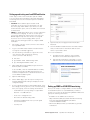
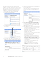
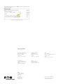
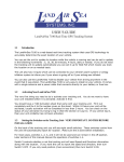
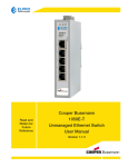
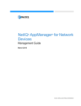
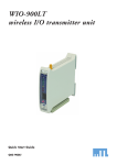
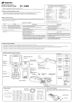
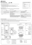
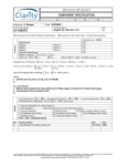
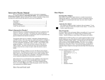
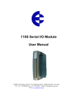
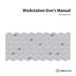
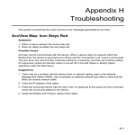
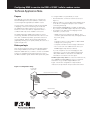
Configuring NMS to monitor the RSSI of 615M-1 cellular modem routers Technical Application Note Purpose To configure NMS to monitor RSSI you need: This application note describes how to configure the Network Management System (NMS) to monitor the received signal strength (RSSI) of 615M-1 routers. • • You may need to monitor RSSI to find out why a 615M is dropping connections. Monitoring can reveal that the 615M has poor RF reception in some areas, or interference from other devices at particular times— conditions that may cause unstabile connections. • • The 615M has built-in SNMP functionality for remote monitoring, and NMS can track and monitor devices over time. This combination provides a powerful solution for monitoring RSSI. Data is reported systematically and graphically, allowing you to quickly identify the cause of a signal strength issue. PC with Ethernet or wireless network access (see Figure 1) Ethernet cables to connect (daisy chain) 615M routers to the PC for configuration purposes (not needed if connecting wirelessly) Merged 615M SNMP MIB file for NMS. To obtain this file, contact your ELPRO support help desk (see below) If you plan to use SMS (text messaging) for alert notification, you also need: • • Before you begin • This document assumes that you have already installed and configured NMS (version 1.0.7 or earlier) and have added the 615M devices you want to monitor to the NMS system. For installation and setup instructions, refer to the NMS installation guide and the NMS quick start guide. SMTP email server settings (host address, port, username, password and security settings) provided by your IT group, OR A gmail account if you are unable to obtain SMTP settings from your IT group Cell phone number for text message notifications The “resolv.conf” file. Obtain this file from your ELPRO support help desk (see below) If you do not plan to use text messaging for alert notification, you can use the default internal email utility within NMS for notifications. No additional information is needed to use this option. ELPRO support help desk: For customers within the US, go to [email protected]. For customers outside the US, go to [email protected]. Figure 1 shows the configuration setup. Detailed instructions are provided in the procedures that follow. Figure 1. Configuration Setup PC running NMS virtual machine Ethernet connection (wired or wireless) Internet Ethernet connection Ethernet connection 615M-1 Cellular Modem and Router 615M-1 Cellular Modem and Router 615M-1 Cellular Modem and Router 615M-1 Cellular Modem and Router Enabling SNMP on the 615M routers The first step is to enable Simple Network Management Protocol (SNMP) functionality on the 615M routers that you want to monitor. SNMP is used by NMS to monitor network devices. 4. Verify that VMware Player can access the c:\CooperNMS\mibfiles directory: a. Open VMware Player. b. On the Virtual Machine menu, click Virtual Machine Settings. 1. Connect the 615M routers to the PC using Ethernet connection (wired or wireless). You can daisy chain the routers, as illustrated in Figure 1. c. Click the Option tab, and then click Shared Folders in the Settings column. d. Verify the following folder settings: 2. Repeat the following steps for each 615M: a. Log on to the 615M Web interface. For detailed instructions refer to the 615M-1 users manual. b. On the main menu, click Diagnostics. • Under Folder Sharing, make sure that the “Always enabled” option is selected. • Under Folders, make sure that the check box for the CooperNMS folder is selected. 5. Log on to the NMS virtual machine: a. From the main VMware Player window, click the cooperNMSvx.x.x image on the left. c. In the Diagnostics window, click the SNMP tab and configure the following settings: • For SNMP, select Enable b. Click “Play virtual machine.” • For Version, select “v2c” • Under Traps, select Disable c. At the localhost login, type “root” and press Enter, and then type the password “cooperadmin” and press Enter. For detailed instructions on running the NMS virtual machine, see the NMS installation guide. 6. Enter the following command to change the directory to the mibfiles shared directory: # cd /mnt/hgfs/mibfiles 7. Enter the following command to list the directory contents. Verify that the MIB file appears in the list. # ls 8. Enter the following command to install the MIB file (in this example, “615--5-0-2-A-final.txt”) into the NMS Linux system: # addmib addmib # addmib 615‐5‐0‐2‐A ‐final.txt d. Click Save and Reset. Loading the 615M SNMP MIB file into NMS The next step is to load the merged 615M SNMP MIB file you received from your ELPRO support help desk into NMS. In this procedure, the example MIB file is named “615-5-02-A-final.txt”. 1. Make sure that your PC has Internet connection. 2. On the PC, open the CooperNMS shared directory, c:\CooperNMS, and create a subdirectory named “mibfiles”, as shown below. c:\CooperNMS\mibfiles 3. Copy the merged 615M SNMP MIB file into the c:\CooperNMS\mibfiles directory. 2 Technical Application Note September 2014 www.eaton.com The SNMP OID entries are now ready to use for 615M RSSI monitoring. Setting up and testing email and SMS notification In this step you will set the notification options in NMS to receive alerts when a problem is detected during RSSI monitoring. There are two notification options—Sendmail and SMTP. • Sendmail. The Sendmail option sends an email notification to the account you specified in your “My Accounts” page within NMS. If you want to use this email notification option, refer to the NMS user’s manual for instructions. • SMTP. The SMTP option allows you to receive notification via SMS (text messaging). In order to use this option you need to obtain a file called “resolv.conf” from your ELPRO support help desk. You will also need a gmail account to use for text messaging. When you are ready, use the following procedure to configure SMTP notification. 1. On your PC, copy the “resolv.conf” file to the shared C:/CooperNMS folder. 8. Open the My Account page and click Notification Methods. 9. Click the Mobile Text tab and enter the mobile number that you want used for notifications and select the name of your mobile carrier. 2. Log on to the NMS virtual machine window with the root login (if not already logged on). 10. To test notifications: 3. Use the following commands to copy the file to the “/etc” directory and overwrite any existing “resolv.conf” file in that directory: a. Click My Accounts, and then, click Send Test Notications on the Notification Options menu. # cd /etc b. Veriy that the information on the page is correct, and then click the Send Test Notifications button. # cp resolv.conf resolv-org.conf # cp /mnt/hgfs/resolv.conf. -f 4. Open a Web browser (preferably Google Chrome™ browser) and access NMS. To access NMS, enter the virtual IP address for NMS, and then click the Access NMS link and enter your username and password. For detailed instructions see see the NMS installation guide. 5. Open the Admin page. 6. On the Admin page, open the System Config menu and click Manage Email Settings to display the email configuration page. 7. If your IT group provided you with SMTP settings, enter the settings you were given. If you do not have settings from your IT group, enter the settings shown below. • Send Mail From: you may change “Cooper NMS” but leave “<root@localhost>” • Host: enter “smtp.gmail.com” • Port: leave the default setting “465” • Username and Password: enter your own gmail account information • Security: SSL Setting up NMS for 615M RSSI monitoring Now you are ready to configure NMS to monitor the RSSI of the 615M modems. For each 615M that you want to monitor, you need to run the Monitoring Wizard in NMS and specify the following information: • IP address of the 615M to be monitored • Object identifier (OID) associated with RSSI monitoring in the pre‑defined 615M MIB file (this OID is “.1.3.6.1.4.1.28586.2.1.4.4.0”) • RSSI levels (dBm) at which you want NMS to generate notifications Technical Application Note September 2014 www.eaton.com 3 The example used in this procedure assumes that the IP address of the 615M is “192.168.1.52”, and that you want NMS to generate a warning notification if the RSSI reaches –100 dBm and a critical notification if the RSSI reaches –110 dBm. You can change these settings at any time. 5. Under Device Details, type a name for the 615M host in the Host Name field. Create a name that you can easily identify when you view the system map. For example, 615M-52-<site name>. 1. On the NMS screen, open the Configure page. 2. Click “Run the Monitoring Wizard”. 3. Click SNMP, and then scroll to the bottom of the page and click Next. 6. Under SNMP Settings, make sure that the SNMP Community, and SNMP Version settings match what you configured when you set up the 615M to enable SNMP earlier in this document. 7. Under SNMP Services, enter the following information: SNMP • OID: the object identifier for the service. For RSSI, the OID is “.1.3.6.1.4.1.28586.2.1.4.4.0”. • Display Name: enter the name of the service as it appears in the Service Status table. • Data Label: enter “RSSI”. • Data Units: the units of measurement to be used for the monitoring test. Enter “dBm”. Match Type: select “Numeric”. • 4. Check that the device address is the IP address of the 615M you are currently configuring, and then click Next. 4 Technical Application Note September 2014 www.eaton.com • Warning Range: set the RSSI threshold that will trigger a warning notification. Enter the threshold as a positive value. For example, to specify an RSSI threshold of “–100”, you would enter “100”. • Critical Range: set the threshold that will trigger a critical notification. • String To Match: leave this field blank. It is not needed for RSSI monitoring. • MIB To Use: the MIB to be referenced. Enter “ELPRO-MIB” (this is the name for 615M OID entries). 8. Select the check box to the right of the RSSI service to enable the RSSI service, and then click Next. Check box Service Status Page 9. Complete the remaining steps in the wizard, and click Apply when finished. To view details about an RSSI service or to generate a performance graph, click the service link within the Service Status page to display the Service Status Details page. 10. Go on to the next procedure to enable notifications. Enabling notifications The last configuration step is to enable NMS notifications in so that the system will send an email or text message if a fault condition is detected. 1. On the NMS screen, open the My Account page. 2. Set the notification preferences as shown in the following screen. For more information about notification preferences, refer to the NMS users manual. Service Status Details Page To graph the RSSI status over time, click the Performance Graphs tab. Checking 615M RSSI level and history NMS offers several ways to check the RSSI level of a specific 615M. You can view high-level status information by displaying the Service Status page or the Network Topology Map. You can also view RSSI levels over a period of days, months, or years by generating a performance graph from the Status Details page. To display the Service Status page, click Service Status on the Details menu of the Home page. NNote: Services are color-coded based on their status. For example, red indicates “critical state” and yellow indicates “warning state”. Look for the color key at the top of the Service Status page. Performance Graph Tab (Service Status Details Page) Technical Application Note September 2014 www.eaton.com 5 Select the time period for the graph from the Time Selection menu on the right. Performance Graph 24-Hour View Eaton’s wireless business www.eaton.com/wireless North America & Latin America 5735 W. Las Positas Suite 100 Pleasanton, CA 94588 United States Telephone: +1 925 924 8500 Australia, New Zealand 9/12 Billabong Street Stafford Queensland 4053 Australia Telephone: +61 7 3352 8600 Southeast Asia 2 Serangoon North Avenue 5 # 06-01 Fu Yu Building, 554911 Singapore Telephone: +65 6645 9888 Europe Hein-Moeller-Straße 7-11 53115 Bonn, Germany Telephone: +49 228 602 5573 China 955 Shengli Road East Area of Zhangjiang High-Tech Park Shanghai, 201201 China Telephone: +86 21 2899 3600 Eaton 1000 Eaton Boulevard Cleveland, OH 44122 United States Eaton.com © 2014 Eaton All Rights Reserved Printed in USA September 2014 Eaton is a registered trademark. All other trademarks are property of their respective owners.