1
Tracer- A Series
——MPPT Solar Charge Controller
User Manual
Models:
Tracer1206A /Tracer1210A
Tracer2210A/Tracer3210A/Tracer4210A
Important Safety Instructions
Please reserve this manual for future review. This manual contains all
instructions of safety, installation and operation for Maximum Power Point
Tracking (MPPT) controller in Tracer-A series ("the controller" is referred in this
manual).
General Safety Information
Read carefully all the instructions and warnings in the manual before
installation.
No user serviceable component inside controller. DO NOT disassemble or
attempt to repair the controller.
Mount the controller indoors. Prevent exposure to the elements and do not
allow water to enter the controller.
Install the controller in well ventilated places, the controller‘s heat sink may
become very hot during operation.
Suggested to install appropriate external fuses/breakers.
Make sure switching off all connections with PV array and the fuse/breakers
close to battery before controller installation and adjustment.
Power connections must remain tight to avoid excessive heating from a loose
connection.
Information générales sur la sécurité
Lisez toutes les instructions et précautions dans le manuel avant
l'installation.
Il n‘y a aucune pièce utilisable pour l‘utilisateur à l‘intérieur du contrôleur. Ne
démontez pas ou n'essayez pas de réparer le contrôleur.
Montez le contrôleur en intérieur. Évitez l'exposition des éléments et ne
laissez pas d'eau entrer dans le contrôleur.
Installez le contrôleur Tracer dans un endroit bien ventilé, le dissipateur de
chaleur de l'Tracer peut devenir très chaud pendant l'utilisation.
Installez les fusibles / coupe-circuits comme indiqué.
Déconnectez le module solaire, le chargeur et le fusible / coupe-circuit
proche de la batterie avant l'installation ou le réglage du contrôleur.
Les connexions d'alimentation doivent rester à proximité pour évier une
chaleur excessive du fait d'une connexion trop lâche.
Contents
1 General Information ............................................................................. 1
1.1Overview....................................................................................... 1
1.2 Characteristics ............................................................................ 2
1.3 Accessories Instructions ............................................................ 3
1.4 Maximum Power Point Tracking Technology ......................... 3
1.5 Battery Charging Stage ............................................................. 5
2 Installation Instructions ........................................................................ 8
2.1 General Installation Notes ......................................................... 8
2.2 PV Array Requirements ............................................................. 8
2.3 Wire Size ..................................................................................... 9
2.4 Mounting .................................................................................... 10
3 Operation ............................................................................................. 12
3.1 Button Operation ...................................................................... 12
3.2 LCD Display .............................................................................. 12
3.3 Parameters setting ................................................................... 14
3.4 Battery Type .............................................................................. 15
4 Protections, Troubleshooting and Maintenance ............................. 18
4.1 Protection .................................................................................. 18
4.2 Troubleshooting ........................................................................ 19
4.3 Maintenance.............................................................................. 19
5 Technical Specifications .................................................................... 21
Annex I Conversion Efficiency Curves ................................................ 23
Annex II Dimensions ............................................................................. 28
1 General Information
1.1 Overview
Appreciate you for choosing MPPT solar charge controller, Tracer-A series.
Based on common positive design and advanced MPPT control algorithm, with
LCD displaying running status, this product is artistic, economical and practical.
With MPPT control algorithm, in any situation, products of this series can fast
and accurately track out the best maximum power point (MPP) of photovoltaic
array, in order to obtain the maximum solar energy in time, which remarkably
improves energy efficiency. There is dual display function: local LCD panel and
remote meter. With Modbus communication protocol interface, it is convenient
for customers to expand applications and monitor in various fields like
telecommunication base station, household system, street lighting system,
wilderness monitoring system, etc.
All-round electronic fault self-test function and enhanced electronic protection
function could furthest avoid damages on system components resulting from
installation errors or system failures.
Feature:
Advanced Maximum Power Point Tracking (MPPT) technology, with
efficiency no less than 99.5%.
High quality components, perfecting system performance, with maximum
conversion efficiency of 98%.
Ultra-fast tracking speed and guaranteed tracking efficiency.
Accurately recognizing and tracking of multiple power points.
Reliable automatic limit function of maximum PV input power, ensuring no
overload under any circumstance.
Wide MPP operating voltage range.
12/24VDC automatically identifying system voltage.
LCD panel display design, dynamically displaying tool‘s operating data and
working condition.
Multiple load control modes: manual control, light ON/OFF, light On+Timer
and test mode.
Support 3 charging preprogram options: Sealed, Gel, Flooded.
Battery temperature compensation function.
Real-time energy statistics function.
With RS-485 communication bus interface and Modbus communication
protocol, it is available to meet various communication requirements in
different situations.
Available
for
EPsolar
network
1
module
(eBox--01)with
protocol
TCP/UDP/SNMP, to realize connection to internet.
Available for PC monitoring and external display unit connecting like MT50
and so on, realizing real-time data checking and parameters setting.
Support software upgrade.
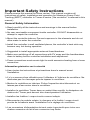
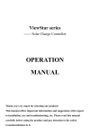
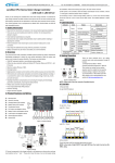
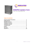
1.2 Characteristics
①
⑩
②
⑨
⑧
③
⑦
④⑤ ⑥
Figure 1-1 Tracer-A Series Characteristics
Item
Name
Item
Name
①
Mounting hole sizeΦ5
⑥
Load Terminal
②
Select Button
⑦
RS-485 port
⑧
Product shell
①
②
③
RTS Port
④
Solar Terminal
⑨
Enter Button
⑤
Battery Terminal
⑩
LCD
Explanation:
① Connection for a RTS (Remote Temperature Sensor) to remotely detect
battery temperature.
② Monitor controller by PC and update controller software via RS485 (RJ45
interface).
2
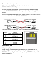
1.3 Accessories Instructions
1. Remote Temperature Sensor (Model: RTS300R47K3.81A)
Acquisition of battery temperature for undertaking temperature compensation of
control parameters, the standard length of the cable is 3m (length can be
customized). The RTS300R47K3.81A connects to the port (3th) on the
controller.
Note: Unplug the RTS, the temperature of battery will be set to a fixed value
25ºC.
2. Remote Meter (Model:MT50)
The digital remote meter displays system operating information, error
indications, parameters setting and self-diagnostics.
3. Super Parameter Programmer (Model: SPP-02)
The SPP-02 can realize one-key setting operation which is suitable for bulk
quantity products setting in the projects.
4. USB To RS-485 converter (Model: CC-USB-RS485-150U)
USB To RS-485 converter is used to monitor each controller on the network
using Solar Station PC software and update the firmware. The length of cable is
1.5m. The CC-USB-RS485-150U connects to the RS-485 Port on the controller.
1.4 Maximum Power Point Tracking Technology
Due to the nonlinear characteristics of solar array, there is a maximum energy
output point (Max Power Point) on its curve. Traditional controllers, with switch
charging technology and PWM charging technology, can‘t charge the battery at
the maximum power point, so can‘t harvest the maximum energy available from
PV array, but the solar charge controller with Maximum Power Point Tracking
(MPPT) Technology can lock on the point to harvest the maximum energy and
deliver it to the battery.
The MPPT algorithm of our company continuously compares and adjusts the
operating points to attempt to locate the maximum power point of the array. The
tracking process is fully automatic and does not need user adjustment.
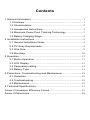
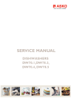
As the Figure 1-2, the curve is also the characteristic curve of the array, the
MPPT technology will ‗boost‘ the battery charge current through tracking the
MPP. Assuming 100% conversion efficiency of the solar system, in that way,
the following formula is established:
Input power (PPV)= Output power (PBat)
Input voltage (VMp) *input current (IPV) =Battery voltage (VBat) *battery current (IBat)
3
Normally, the VMp is always higher than VBat, Due to the principle of conservation
of energy, the IBat is always higher than IPV. The greater the discrepancy
between VMp &VBat, the greater the discrepancy between I PV& IBat. The greater
the discrepancy between array and battery, the bigger reduction of the
conversion efficiency of the system, thus the controller‘s conversion efficiency
is particularly important in the PV system.
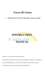
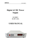
Figure 1-2 is the maximum power point curve, the shaded area is charging
range of traditional solar charge controller (PWM Charging Mode), it can
obviously diagnose that the MPPT mode can improve the usage of the solar
energy resource. According to our test, the MPPT controller can raise 20%-30%
efficiency compared to the PWM controller. (Value may be fluctuant due to the
influence of the ambient circumstance and energy loss.)
Figure 1-2 Maximum Power Point Curve
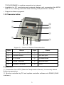
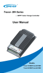
In actual application, as shading from cloud, tree and snow, the panel maybe
appear Multi-MPP, but in actually there is only one real Maximum Power Point.
As the below Figure 1-3 shows:
Figure 1-3 Mutil-MPP Curve
4
If the program works improperly after appearing Multi-MPP, the system will not
work on the real max power point, which may waste most solar energy
resources and seriously affect the normal operation of the system. The typical
MPPT algorithm, designed by our company, can track the real MPP quickly and
accurately, improve the utilization rate of the array and avoid the waste of
resources.
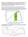
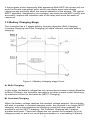
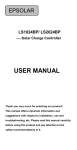
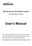
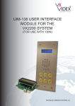
1.5 Battery Charging Stage
The controller has a 3 stages battery charging algorithm (Bulk Charging,
Constant Charging and Float Charging) for rapid, efficient, and safe battery
charging.
Figure 1-4 Battery changing stage Curve
A) Bulk Charging
In this stage, the battery voltage has not yet reached constant voltage (Equalize
or Boost Voltage), the controller operates in constant current mode, delivering
its maximum current to the batteries (MPPT Charging).
B) Constant Charging
When the battery voltage reaches the constant voltage setpoint, the controller
will start to operate in constant charging mode, this process is no longer MPPT
charging, and in the meantime the charging current will drop gradually, the
process is not the MPPT charging. The Constant Charging has 2 stages,
equalize and boost. These two stages are not carried out constantly in a full
charge process to avoid too much gas precipitation or overheating of battery.
5
Boost Charging
The Boost stage maintain 2 hours in default, user can adjust the constant time
and preset value of boost voltage according to demand.
The stage is used to prevent heating and excessive battery gassing.
Equalize Charging
WARNING: Explosive Risk!
Equalizing flooded battery would produce explosive gases, so
well ventilation of battery box is recommended.
CAUTION: Equipment damage!
Equalization may increase battery voltage to the level that
damages sensitive DC loads. Verify that all load allowable
input voltages are 11% greater than the equalizing charging set
point voltage.
CAUTION: Equipment damage!
Over-charging and excessive gas precipitation may damage the
battery plates and activate material shedding on them. Too high
an equalizing charge or for too long may cause damage.
Please carefully review the specific requirements of the battery
used in the system.
AVERTISSEMENT: Risque d‘explosion!
l'égalisation de batteries noyées peut produire des gaz explosifs,
donc il est recommandé de bien ventiler le boitier de la batterie.
ATTENTION: Dégât sur l'équipement!
L'égalisation peut augmenter la tension de la batterie jusqu'à un
niveau nuisible pour les charges CC sensibles. Vérifiez que la
tension d'entrée autorisées de toutes les charges disponibles
sont supérieures à 11% à la tension du point d'installation de
chargement d'égalisation.
ATTENTION: Dégât sur l'équipement!
Un chargement excessif et une précipitation de gaz peut
endommager les plaques de la batterie et la formation de
matières actives dessus. Un chargement trop fort ou une
égalisation prolongée peut causer des dégâts. Inspectez
soigneusement les conditions spécifiques de la batterie utilisée
dans le système.
6
Some types of batteries benefit from equalizing charge on a regular basis,
which is able to stir electrolyte, balance battery voltage and accomplish
chemical reaction. Equalizing charge increases battery voltage, higher than the
standard complement voltage, which gasifies the battery electrolyte.
The controller will equalize the battery on 28th each month. The constant
equalization period is 0~180 minutes. If the equalization isn‘t accomplished in
one-time, the equalization recharge time will be accumulated until the set time is
finished. Equalize charge and boost charge are not carried out constantly in a
full charge process to avoid too much gas precipitation or overheating of battery.
Note:
1) Due to the influence of ambient circumstance or load working, the
battery voltage can’t be steady in constant voltage, controller will
accumulate and calculate the time of constant voltage working. When the
accumulated time reach to 3 hours, the charging mode will turn to Float
Charging.
2) If the controller time is not adjusted, the controller will equalize charge
battery once every month following the inner time.
C) Float Charging
After the Constant voltage stage, the controller will reduce charging current to
Float Voltage setpoint. This stage will have no more chemical reactions and all
the charge current transforms into heat and gas at this time. Then the controller
reduces the voltage to the floating stage, charging with a smaller voltage and
current. It will reduce the temperature of the battery and prevent the gassing
and charging the battery slightly at the same time. The purpose of Float stage
is to offset the power consumption caused by self consumption and small loads
in the whole system, while maintaining full battery storage capacity.
In Float charging stage, loads are able to obtain almost all power from solar
panel. If loads exceed the power, the controller will no longer be able to maintain
battery voltage in Float charging stage. If the battery voltage remains below the
Recharge Voltage, the system will leave Float charging stage and return to Bulk
charging stage.
7
2 Installation Instructions
2.1 General Installation Notes
Before installation, please read through the entire installation instructions to
get familiar with the installation steps.
Be very careful when installing the batteries, especially flooded lead-acid
battery. Please wear eye protection, and have fresh water available to wash
and clean any contact with battery acid.
Keep the battery away from any metal objects, which may cause short circuit
of the battery.
Explosive battery gases may come out from the battery during charging, so
make sure ventilation condition is good.
Gel, Sealed or Flooded batteries are recommended, other kinds please refer
to the battery manufacturer.
Ventilation is highly recommended if mounted in an enclosure. Never install
the controller in a sealed enclosure with flooded batteries! Battery fumes from
vented batteries will corrode and destroy the controller circuits.
Loose power connections and corroded wires may result in high heat that can
melt wire insulation, burn surrounding materials, or even cause fire. Ensure
tight connections and use cable clamps to secure cables and prevent them
from swaying in mobile applications.
Battery connection may be wired to one battery or a bank of batteries. The
following instructions refer to a singular battery, but it is implied that the
battery connection can be made to either one battery or a group of batteries in
a battery bank.
Multiple same models of controllers can be installed in parallel on the same
battery bank to achieve higher charging current. Each controller must have its
own solar module(s).
Select the system cables according to 5A/mm2 or less current density in
accordance with Article 690 of the National Electrical Code, NFPA 70.
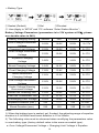
2.2 PV Array Requirements
The MPPT controller will limit battery charging current to the Rated Charge
Current. Although the controller can harvest the rated power of controller, the
PV array size can be as high as P Max (PMax=IBat*VMp), assuming that the VMp is
68V, the acceptable PV array size as below:
8
Model
Rated Charge
Current (IBat)
Rated Charge Power
MAX. PV Power
(PMax)
Tracer1206A
10A
130W/12V, 260W/24V
340W(VMP=34V)
Tracer1210A
10A
130W/12V, 260W/24V
680W
Tracer2210A
20A
260W/12V, 520W/24V
1360W
Tracer3210A
30A
390W/12V, 780W/24V
2040W
Tracer4210A
40A
520W/12V,1040W/24V
2720W
Note:
1) The calculation formula for reference only, the PV array Voc (Open Circuit
Voltage) must never exceed 100V under any conditions.
2) The array Isc (Short Circuit Current) must not exceed the rated charge current
of controller.
3) The Voc of photovoltaic array could be affected by ambient temperature,
fluctuating a bit. Before connecting solar panel, please ensure the Voc at any
temperature not exceeding the maximum open-circuit voltage of controller.
2.3 Wire Size
The wiring and installation methods must conform to all national and local
electrical code requirements.
PV Wire Size
Since the PV outputs can vary due to the array connection method, the
minimum wire size must according with maximum array short-circuit current.
For example,
The rated charge current of Tracer4210A is 40A, the PV maximum power is
1040W (24V system). If the VMp is 34V, the ISC is 30A (ISC=1040W/34V), then
the PV wire size must be not less than 10mm2 (6AWG); If the VMp is 68V, the ISC
is 5A (ISC=1040W/68V), then the PV wire size must be not less than 6mm2
(10AWG).
Battery and Load Wire Size
The battery and load wire size must conform to the rated current, the reference
size as below:
9
Model
Rated
charge
current
Rated
discharge
current
Battery wire
size
(mm2/AWG)
Load wire
size
(mm2/AWG)
Tracer1206A
Tracer1210A
10A
10A
4/10
4/10
Tracer2210A
20A
20A
6/8
6/8
Tracer3210A
30A
30A
10/6
10/6
Tracer4210A
40A
40A
16/4
16/4
Note: The wire size is only for reference. If there is a long distance between the
PV array and the controller or between the controller and the battery, larger
wires can be used to reduce the voltage drop and improve performance.
2.4 Mounting
CAUTION: The controller requires at least 150mm of clearance
above and below for proper air flow. Ventilation is highly
recommended if mounted in an enclosure.
WARNING: Risk of explosion! Never install the controller in a
sealed enclose with flooded batteries! Do not install in a confined
area where battery gas can accumulate.
WARNING: Risk of electric shock!
Exercise caution when handling solar wiring. The solar PV array
can produce open-circuit voltages in excess of 100 V when in
sunlight. Pay more attention to it.
ATTENTION: Le contrôleur Tracer nécessite au moins un
espace libre de 150mm au dessus et en dessous pour une
circulation correcte de l'air. Une ventilation est hautement
recommandée en cas d'installation dans un boitier.
AVERTISSEMENT: Risque d‘explosion ! N'installez jamais le
Tracer dans un boitier fermé avec des batteries noyées!
N'installez pas dans un espace confiné où des gaz de batterie
peuvent s'accumuler.
AVERTISSEMENT: Risque d'électrochoc!
Faites attention lors de la manipulation des connexions solaires.
La matrice PV solaire peut produire des tensions supérieures à
100V, à la lumière du soleil. Soyez particulièrement attentif à
cela.
10
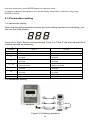
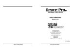
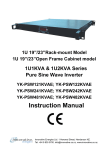
Figure 2-1 Mounting
1. Connect components to the charge controller in the sequence as shown
above and pay much attention to the ―+‖ and ―-‖. Please don‘t turn on the fuse
during the installation. When disconnecting the system, the order will be
reserved.
2. After installation, power the controller and check the LCD on. If it‘s not on,
please refer to chapter 4. Always connect the battery first, in order to allow the
controller to recognize the system voltage.
3. The battery fuse should be installed as close to battery as possible. The
suggested distance is within 150mm.
4. The Tracer-A series is a positive ground controller. Any positive connection
of solar, load or battery can be earth grounded as required.
CAUTION: Unplug the RTS, the temperature of battery will be set to
a fixed value 25 ºC.
CAUTION: Please connect the inverter to the battery rather than to
the controller, if the inverter is necessary.
11
3 Operation
3.1 Button Operation
Mode
Browse Mode
Set Mode
Load Switch
Note
Short press SELECT
Long press ENTER to enter into Set Mode, short press SELECT
to set the parameters. The LCD will leave SET Mode interface
automatically when no operation for more than ten seconds
When the load mode is manual on/off, short press ENTER can
turn on/off the load
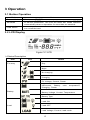
3.2 LCD Display
Figure 3-1 LCD
Status Description
Item
PV array
Icon
Status
Day
Night
No charging
Charging
PV Voltage, Current, Power
High
volt disconnect, Low voltage
disconnect, Battery over temperature,
Charging, Power
Battery
Battery Voltage, Current, Temperature
Battery Type
Load ON
Load
Load OFF
Load Voltage, Current, Load mode
12
Fault Indication
Status
Icon
Description
Battery over
discharged
Battery level shows empty, battery frame
blink, fault icon blink
Battery over
voltage
Battery level shows full, battery frame blink,
fault icon blink
Battery over
temperature
Battery level shows current value, battery
frame blink, fault icon blink
Load failure
Load overload ,Load short circuit
Auto cycle interface
Browse interface
Note: 1) Accumulative power zero clearing: Under PV power interface, long press ENTER and
13
then the value blink, press ENTER again to clear the value.
2) Switching battery temperature unit: Under battery temperature interface, long press
ENTER to switch.
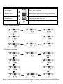
3.3 Parameters setting
Load mode setting
When the browsing interface shows the load setting interface as following, you
can set the load modes.
From left to right, the fist number means Time 1 or Time 2, the second and third
number means as following:
The 2nd, 3rd
number
n
0
1
2
3~13
14
15
16
17
Time 1
Time 2
Disable
Dusk to dawn
Load will be on for 1 hour since
sunset
Load will be on for 2 hour since
sunset
Load will be on for 3~ 13 hour
since sunset
Load will be on for 14 hour since
sunset
Load will be on for 15 hour since
sunset
Test mode
Manual ON/OFF
Disable
Display n
Load will be on for 1 hour before
sunrise
Load will be on for 2 hour before
sunrise
Load will be on for 3~13 hour
before sunrise
Load will be on for 14 hour before
sunrise
Load will be on for 15 hour before
sunrise
Display n
Display n
Parameters setting
Figure 3-2 Setting operation
14
Three methods to configure the controller:
1–Remote meter, MT50 (Use standard twisted net cable, model:
CC-RS485-RS485-200U-MT).
2–Super parameter programmer, SPP-02(Use standard twisted net cable,
model: CC-RS485-RS485-200U). One-key easily configure and apply to batch
setting.
3–PC monitoring setting software ―Solar Station Monitor‖(Use USB to RS485
converter cable with model: CC-USB-RS485-150U.
The RJ45 interface pin define for Tracer-A series controller is shown below:
Pins
Define
1
Power supply output +7.5V
2
Power supply output +7.5V
3
RS-485-B
4
RS-485-B
5
RS-485-A
6
7
RS-485-A
Ground
8
Ground
3.4 Battery Type
Operating Steps
Under Battery Voltage interface, long press ENTER button enter into the
interface of Battery type setting. After choosing the battery type by pressing
SELECT button, waiting for 5 seconds or pressing ENTER button again to
modify successfully.
15
Battery Type
①Sealed (Default)
②Gel
③Flooded
④ User(Apply to ―MT50‖ and ―PC software ―Solar Station Monitor‖)
Battery Voltage Parameters (parameters is in 12V system at 25℃, please
use double value in 24V.)
Battery charging setting
Sealed
Gel
Flooded
16.0V
16.0V
16.0V
9~17V
15.0V
15.0V
15.0V
9~17V
15.0V
15.0V
15.0V
9~17V
14.6V
——
14.8V
9~17V
Boost Charging Voltage
14.4V
14.2V
14.6V
9~17V
Float Charging Voltage
13.8V
13.8V
13.8V
9~17V
13.2V
13.2V
13.2V
9~17V
12.6V
12.6V
12.6V
9~17V
12.2V
12.2V
12.2V
9~17V
Under Volt. Warning Volt.
12.0V
12.0V
12.0V
9~17V
Low Volt. Disconnect Volt.
11.1V
11.1V
11.1V
9~17V
Discharging Limit Voltage
10.6V
10.6V
10.6V
Equalize Duration (min.)
120
——
120
0~180
Boost Duration (min.)
120
120
120
10~180
Over Voltage Disconnect
Voltage
Charging Limit Voltage
Over Voltage Reconnect
Voltage
Equalize Charging
Voltage
Boost Reconnect
Charging Voltage
Low Voltage Reconnect
Voltage
Under Voltage Warning
Reconnect Voltage
User
9~17V
Note:
1) When the battery type is sealed, gel, flooded, the adjusting range of equalize
duration is 0 to180min and boost duration is 10 to180min.
2) The following rules must be observed when modifying the parameters value
in user battery type (factory default value is the same as sealed type):
a. Over Voltage Disconnect Voltage > Charging Limit Voltage ≥ Equalize
16
Charging Voltage ≥ Boost Charging Voltage ≥ Float Charging Voltage >
Boost Reconnect Charging Voltage.
b. Over Voltage Disconnect Voltage > Over Voltage Reconnect Voltage
c. Low Voltage Reconnect Voltage > Low Voltage Disconnect Voltage ≥
Discharging Limit Voltage.
d. Under Voltage Warning Reconnect Voltage > Under Voltage Warning
Voltage ≥ Discharging Limit Voltage.
e. Boost Reconnect Charging voltage > Low Voltage Disconnect Voltage.
CAUTION: Please refer to user guide or contact with the sales for
the detail of setting operation.
17
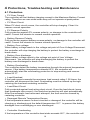
4 Protections, Troubleshooting and Maintenance
4.1 Protection
PV Over Current
The controller will limit battery charging current to the Maximum Battery Current
rating. Therefore an over-sized solar array will not operate at peak power.
PV Short Circuit
When PV short circuit occurs, the controller will stop charging. Clear it to
resume normal operation.
PV Reverse Polarity
Fully protection against PV reverse polarity, no damage to the controller will
result. Correct the miswire to resume normal operation.
Battery Reverse Polarity
Fully protection against battery reverse polarity, no damage to the controller will
result. Correct the miswire to resume normal operation.
Battery Over voltage
When battery voltage reach to the voltage set point of Over Voltage Disconnect,
the controller will stop charging the battery to protect the battery overcharge to
break down.
Battery Over discharge
When battery voltage reach to the voltage set point of Low Voltage
Disconnect , the controller will stop discharging the battery to protect the
battery over discharged to break down.
Battery Overheating
The controller detect the battery temperature through the external temperature
sensor. If the battery temperature exceeds 65ºC, the controller will
automatically start the overheating protection to stop working and recover
below 50 ºC.
Load Overload
If the load current exceeds the maximum load current rating 1.05 times, the
controller will disconnect the load. Overloading must be cleared up through
reducing the load and restarting controller.
Load Short Circuit
Fully protected against load wiring short-circuit. Once the load shorts (more
than quadruple rate current), the load short protection will start automatically.
After five automatic load reconnect attempts, the fault must be cleared by
restarting controller.
Damaged Remote Temperature Sensor
If the temperature sensor is short-circuited or damaged, the controller will be
charging or discharging at the default temperature 25℃ to prevent the battery
damaged from overcharging or over discharged.
Controller Overheating
If the temperature of the controller heat sinks exceeds 85℃, the controller will
18
automatically start the overheating protection and recover below 75℃.
High Voltage Transients
PV is protected against small high voltage surge. In lightning prone areas,
additional external suppression is recommended.
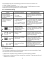
4.2 Troubleshooting
Faults
The LCD is off
during daytime
when sunshine falls
on PV modules
properly
Possible reasons
Wire connection is
correct, LCD not
display
1. Battery voltage is
Confirm that PV and battery
wire connections are correct
and tight
PV array
disconnection
lower than 9V
2. PV voltage is less
than battery voltage
Interface
blink
Interface
blink
Interface
blink
Interface
blink
Troubleshooting
1. Please check the voltage of
battery. At least 9V voltage to
activate the controller
2. Check the PV input voltage
which should be higher than
battery‘s
Battery voltage
higher than over
voltage disconnect
voltage(OVD)
Check if the battery voltage is
too high, and disconnect the
solar module
Battery under
voltage
Load output is normal,
charging LED indicator will
return to green automatically
when fully charged
Battery low voltage
disconnect
Over load or Short
circuit
The controller will cut off the
output automatically, LED
indicator will return to green
automatically when fully
charged
Remove or reduce the load
and press the button, the
controller will resume to work
after 3 seconds
4.3 Maintenance
The following inspections and maintenance tasks are recommended at least
two times per year for best performance.
Make sure controller firmly installed in a clean and dry ambient.
Make sure no block on air-flow around the controller. Clear up any dirt and
fragments on radiator.
19
Check all the naked wires to make sure insulation is not damaged for serious
solarization, frictional wear, dryness, insects or rats etc. Repair or replace
some wires if necessary.
Tighten all the terminals. Inspect for loose, broken, or burnt wire connections.
Check and confirm that LED is consistent with required. Pay attention to any
troubleshooting or error indication .Take corrective action if necessary.
Confirm that all the system components are ground connected tightly and
correctly.
Confirm that all the terminals have no corrosion, insulation damaged, high
temperature or burnt/discolored sign, tighten terminal screws to the
suggested torque.
Check for dirt, nesting insects and corrosion. If so, clear up in time.
Check and confirm that lightning arrester is in good condition. Replace a new
one in time to avoid damaging of the controller and even other equipments.
WARNING:Risk of electric shock!
Make sure that all the power is turned off before above operations,
and then follow the corresponding inspections and operations.
20
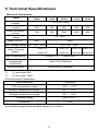
5 Technical Specifications
Electrical Parameters
Item
Nominal system
voltage
Rated charge
current
Rated discharge
current
Battery voltage
range
Max. PV VOC
Tracer
1206A
Tracer
1210A
Tracer
2210A
Tracer
3210A
Tracer
4210A
20A
30A
40A
20A
30A
40A
12/24VDC Auto
10A
10A
10A
10A
9V~32V
60V
100V
MPP Voltage range VBAT①+2V~50V②
Max. PV input
power
③
VBAT +2V~90V
130W/12V
260W/12V
390W/12V 520W/12V
260W/24V
520W/24V
780W/24V 1040W/24V
Self-consumption
<20mA(12V)
<16mA(24V)
Temperature
compensate
coefficient
-3mV/ºC/2V(Default)
Communication
RS485(RJ45 interface)
①
②
③
VBAT is Battery voltage.
Voc less than 60V.
Voc less than 100V.
Environmental Parameters
Environmental
Parameter
LCD temperature range
-20℃~+70℃
Ambient temperature range*
-25℃~+45℃
Storage temperature range
-35℃~+80℃
Humidity range
≤95% (N.C.)
Enclosure
IP30
* Please operate controller at permitted ambient temperature. If over
permissible range, please derate capacity in service.
21
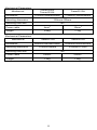
Mechanical Parameters
Mechanical
Dimension
Tracer1206A
Tracer1210A
Tracer2210A
172mmx139mmx44mm
172mmx139mmx44mm
Mounting dimension
130mmx130mm
Φ5
Mounting hole size
Power cable
4mm2
10mm2
Weight
0.6kg
1.1kg
Mechanical Parameters
Mechanical
Dimension
Mounting dimension
Tracer3210A
Tracer4210A
228mmx164mmx55mm
252mmx180mmx63mm
170mmx164mm
Power cable
Weight
210mmx171mm
Φ5
Mounting hole size
10mm2
10mm2
1.2kg
1.9kg
22
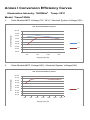
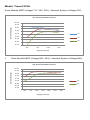
Annex I Conversion Efficiency Curves
Illumination Intensity: 1000W/m2 Temp: 25ºC
Model: Tracer1206A
1.
Solar Module MPP Voltage(17V, 34V) / Nominal System Voltage(12V)
12V Conversion Efficency Curves
100.00%
Conversion Efficency(η%)
98.00%
96.00%
94.00%
92.00%
17V
90.00%
88.00%
34V
86.00%
84.00%
20W
50W
100W
130W
Charging Power (W)
Solar Module MPP Voltage(34V) / Nominal System Voltage(24V)
24V Conversion Efficency Curves
100.00%
98.00%
Conversion Efficency(η%)
2.
96.00%
94.00%
92.00%
90.00%
34V
88.00%
86.00%
84.00%
20W
50W
100W
150W
200W
Charging Power (W)
250W
300W
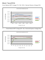
Model: Tracer1210A
Solar Module MPP Voltage(17V, 34V, 68V) / Nominal System Voltage(12V)
12V Conversion Efficency Curves
100.00%
Conversion Efficency(η%)
98.00%
96.00%
94.00%
92.00%
17V
90.00%
34V
88.00%
68V
86.00%
84.00%
20W
50W
100W
130W
Charging Power (W)
Solar Module MPP Voltage(34V, 68V) / Nominal System Voltage(24V)
24V Conversion Efficency Curves
100.00%
98.00%
Conversion Efficency(η%)
1.
96.00%
94.00%
92.00%
90.00%
34V
88.00%
68V
86.00%
84.00%
20W
50W
100W
150W
200W
Charging Power (W)
250W
300W
Model: Tracer2210A
Solar Module MPP Voltage(17V, 34V, 68V) / Nominal System Voltage(12V)
12V Conversion Efficency Curves
99.00%
Conversion Efficency(η%)
97.00%
95.00%
93.00%
17
91.00%
34V
89.00%
68V
87.00%
85.00%
20W
50W
100W
150W
200W
250W
Charging Power (W)
1.
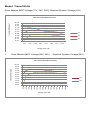
Solar Module MPP Voltage(33V, 68) / Nominal System Voltage(24V)
24V Conversion Efficency Curves
97.00%
95.00%
93.00%
91.00%
34V
89.00%
68V
87.00%
Charging Power (W)
550W
500W
450W
400W
350W
300W
250W
200W
150W
50W
100W
85.00%
20W
Conversion Efficency(η%)
99.00%
Model: Tracer3210A
Solar Module MPP Voltage(17V, 34V, 68V)/ Nominal System Voltage(12V)
12V Conversion Efficency Curves
100.00%
Conversion Efficency(η%)
99.00%
98.00%
97.00%
96.00%
95.00%
17V
94.00%
34V
93.00%
92.00%
68V
91.00%
90.00%
50W
100W
150W
200W
250W
300W
350W
400W
Charging Power (W)
Solar Module MPP Voltage(34V, 68V) / Nominal System Voltage(24V)
24V Conversion Efficency Curves
100.00%
99.00%
98.00%
97.00%
96.00%
95.00%
94.00%
34V
93.00%
68V
92.00%
91.00%
Charging Power (W)
800W
750W
700W
650W
600W
550W
500W
450W
400W
350W
300W
250W
200W
150W
50W
90.00%
100W
Conversion Efficency(η%)
1.
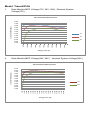
Model: Tracer4210A
1.
Solar Module MPP Voltage(17V, 34V, 68V) / Nominal System
Voltage(12V)
12V Conversion Efficency Curves
98.00%
97.00%
Conversion Efficency(η%)
96.00%
95.00%
94.00%
93.00%
92.00%
17V
91.00%
34V
90.00%
89.00%
68V
88.00%
550W
500W
450W
400W
350W
300W
250W
200W
150W
50W
100W
87.00%
Charging Power (W)
Solar Module MPP Voltage(34V, 68V) Nominal System Voltage(24V)
24V Conversion Efficency Curves
99.00%
98.00%
97.00%
96.00%
95.00%
94.00%
93.00%
92.00%
34V
91.00%
90.00%
68V
89.00%
88.00%
Charging Power (W)
1000W
950W
900W
850W
800W
750W
700W
650W
600W
550W
500W
450W
400W
350W
300W
250W
200W
50W
150W
87.00%
100W
Conversion Efficency(η%)
2.
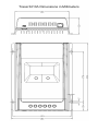
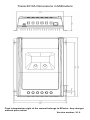
Annex II Dimensions
Tracer1206A/Tracer1210A Dimensions in Millimeters
Tracer2210A Dimensions in Millimeters
Tracer3210A Dimensions in Millimeters
Tracer4210A Dimensions in Millimeters
Final interpretation right of the manual belongs to EPsolar. Any changes
without prior notice!
Version number: V1.0
BEIJING EPSOLAR TECHNOLOGY CO., LTD.
Tel: +86-10-82894112 / 82894962
Fax: +86-10-82894882
E-mail:[email protected]
Website: http://www.epsolarpv.com/
http://www.epever.com/