1
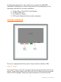
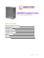
TABLE OF CONTENTS Important Safety Information 2 Getting Started 2 SORAPRO Hardware 3 Installation Overview 4 Installation Checklist 5 Troubleshooting 6 Support 7 Warranty 8 Appendix A 10 1 SORAPRO VC1.1 User Manual IMPORTANT SAFETY INFORMATION This manual contains important safety and operating information. Please read and follow the instructions in this manual. Failure to do so could be hazardous and result in damage to the hardware. DANGER! HIGH VOLTAGE HAZARD INSTALLATION OF ANY SORAPRO IS FOR QUALIFIED PERSONNEL ONLY. TO AVOID ELECTRICAL SHOCK, DO NOT INSTALL OR SERVICE ANY SORAPRO HARDWARE UNLESS YOU ARE A QUALIFIED TO DO SO GETTING STARTED This guide will help you properly install the SORAPRO monitoring equipment. It is important to read through all of the installation steps prior to installing any equipment. Read through the instructions, visualize where all the equipment will need to be installed and do a soft installation before mounting any equipment. If you do not understand the instructions in full, please contact SORAPRO Support at 609-807-8307. How SORAPRO Works: SORAPRO was developed to be easy to install while providing Real Time energy metering and monitoring from anywhere on the planet. The metering equipment gathers data from the site through Current Tranformers (CTs). This information is transferred to remote servers through an internet gateway and is processed for accuracy before being stored. Once stored, this data is analyzed to establish if the solar array is working properly, based on criteria specified by the installer through the user interface. Any discrepancies are reporting in real time to specified users as warning or errors through email alerts. The errors will continuously report to the users until the discrepancies are rectified. Inside this Package: Prior to commencing installation, please confirm that the following components were received in your SORAPRO installation package. 1. 2. 3. 4. Enclosure Metering equipment (pre-assembled) Wall mounting hardware Current Transformers (4 total; 2 for solar and 2 for load) 2 SORAPRO VC1.1 User Manual The following equipment is also required to complete the SORAPRO installation. Manufacturer of each component will vary depending on the equipment specified for the solar installation. 1. 2. 3. 4. 2-Pole 10A or 2-Pole 20A Circuit Breaker 12 AWG, 600V wire ¾” Conduit (or larger) CAT5 cable (Powerline Device when necessary) SORAPRO HARDWARE This unit is equipped with three sets of inputs and two indicator LEDs. LOAD CT Inputs: The Load CT input is the first connection block from the left hand side of the device. These inputs read current flow from the CTs that have been supplied with the VR01 package. Please pay special attention to the direct of the 3 SORAPRO VC1.1 User Manual current flow through the CTs. The LED indicator light will notify you of the direction the current is flowing. SOLAR CT Inputs: The Solar CT input is the second connection block from the left hand side of the device. These inputs read current flow from the CTs that have been supplied with the VR01 package. Meter: The unit contains a metering device for measuring power data. The unit uses current transformers to measure amperage through a wire. DO NOT USE ANY OTHER CT’s WITH THIS DEVICE THAN THE ONES CONTAINED IN THE SORAPRO PACKAGE. Use of other CT’s could damage metering equipment and cause product failures. The data is measured by the metering device and send via RS485 transmission the data acquisition center for logging and transmission through the internet gateway. The Load Side monitoring unit contains a metering device with multiple inputs. One input is labeled “LOAD” and the second input is labeled “PV”. To ensure proper data collection, make sure to connect the corresponding CT’s to the correct meter. PV – CT’s should be connected to the output of the solar subpanel which is combining the AC power of all of the systems inverters. LOAD – CT’s should be connected to the input of the main service panel where power is being supplied to the building, not the PV output. Data Acquisition Server: The meter contains a data acquisition gateway and transmits data through an Ethernet connection. The data is time stamped and stored in onboard memory. Using an Ethernet connection, this data is pushed to SORAPRO data servers through an internet gateway using HTTP protocol. INSTALLATION OVERVIEW See Appendix A for a Quick Installation Guide. 4 SORAPRO VC1.1 User Manual To install the device, follow the following steps and reference the Quick Installation Guide. 1. Choose a location for the SORAPRO unit that is within 6’ of the solar output source. You may connect the device to the main interconnection panel or a solar subpanel as long as the device is within 6’ from the source to be metered and there are enough open breaker spaces to connect the proper breaker to. 2. The SORAPRO unit will need a 2p10A or 2p20a breaker in a single phase application. 3. Install the breaker to supply AC power to the unit. In order to ensure proper metering, the CTs must be installed in the same panel as the breaker you are installing in this step. 4. Install a conduit from the breaker panel to the SORAPRO device. 5. Using the conduit from step 6, run wire, in accordance with NEC code, from the breaker panel to the SORAPRO device. 6. Install the CTs on the LOAD input. 7. Install the CTs on the Solar input. 8. Connect the AC supply wire from the breaker to the terminal block: N, L1, and L2, respectively. 9. Connect the Ethernet (LAN) wire on the bottom of the Data Acquisition device. 10. Turn on power to the SORAPRO device and ensure the following: a. A green status LED is blinking b. The CT indicator lights are showing current flowing in the proper direction. 11. Call SORAPRO to complete the commissioning of the device with the SORAPRO online software. INSTALLATION CHECKLIST Always contact the local network administrator and verify the following: 1. Network Port 80 is open for both incoming and outgoing signals 2. The network router is configured to use DHCP. After installing SORAPRO hardware, make sure the following has been completed before leaving the site: 1. The CTs are installed on the correct lines and that they are facing the correct direction of current flow. 2. All accessories that you have installed have been installed according to their installation manuals. 3. After you have verified that the installation has been done correctly, call SORAPRO to activate the device at (855) 767-2776 5 SORAPRO VC1.1 User Manual TROUBLESHOOTING Line voltages up to 600 VAC are present on the input terminals of the device and throughout the connected line circuits during normal operation. THESE VOLTAGES MAY CAUSE SEVERE INJURY OR DEATH. Installation and servicing must be performed only by qualified, properly trained personnel. The following tools are helpful in diagnosing hardware installation issues: 1. Digital Multimeter capable of mV AC and mA AC measurements. 2. Clamp on Amp meter to verify current in line (if possible). 3. Basic electrician tools. LED State Condition The LED status key for the LED to the right of the load CTs: LED Off – No or low current on both CT1 and CT2 Blue – Current flowing forward on CT1 and no or low current on CT2 Teal – Current flowing forward on CT1 and CT2 Green – Current flowing forward on CT2 and no or low current on CT1 Yellow Blink – Current flowing backwards on CT1 Red Blink – Current flowing backwards on CT2 Red – Current flowing backwards on CT1 and CT2 Normal Operation Indicator Lights PV CT’s with Solar Running Teal – Current flowing forward on CT1 and CT2 LOAD CT’s (lights may very base on solar system size) Solar Turned on > Red Current flowing backwards on CT1 and CT2 Solar Turned Off > Teal Current flowing forward on CT1 and CT2 ***at the time of installation, check the utilities' net meter to determine if power is backflowing to them*** 6 SORAPRO VC1.1 User Manual SUPPORT We encourage your feedback. Please contact us by mail at: Future Solutions Technologies, LLC 120 Route 156 Yardville, NJ 08620 Phone Support is available between the hours of 8:00AM and 6:00PM EST. For phone support, please call: (855)767-2776 (Phone) Email Support is also available at: [email protected] Copyright 2012 Future Solutions Technologies, LLC. All rights reserved. No part of this document may be reproduced, stored in a retrieval system, or transmitted, in any form or by any means, electronic, mechanical, photographic, magnetic or otherwise, without the express written consent of Future Solutions Technologies, LLC. Future Solutions Technologies, LLC does not make representations, express or implied, with respect to this documentation or any of the equipment and/or software it may describe, including any implied warranties of utility, merchantability, or fitness for any purpose. All such warranties are expressly disclaimed. Neither Future Solutions Technologies, LLC, nor its distributors or dealers shall be liable for any indirect, incidental, or consequential damages under any circumstances. The exclusion of implied warranties may not apply in all cases under some statutes, and thus the above exclusion may not apply. Specifications are subject to change without notice. Every attempt has been made to make this document complete, accurate, and up to date. Readers are cautioned that Future Solutions Technologies, LLC, reserves the right to make changes without notice and shall not be responsible for any damages, including indirect, incidental or consequential damages, caused by reliance on the material presented, including, but not limited to omissions, typographical errors, arithmetical errors or listing errors in the content material. Future Solutions Technologies, LLC 120 Route 156 Yardville, NJ 08620 U.S.A 7 SORAPRO VC1.1 User Manual WARRANTY 5 Year Warranty A five year warranty applies to the following products: VR01, VR11, VC11, VC21. Extended Warranty An extended 5 year warranty can be purchased for any device with a 5 Year Standard warranty. This extended warranty is an extension of 5 years on the Standard Warranty, from the date of the original warranty period. Please contact the SORAPRO service line at (855)SORAPRO for more details regarding the extended warranty. The Standard Warranty covers any repair or replacement costs incurred during the warranty period, beginning on the device’s purchase date, subject to the following conditions. Warranty Conditions If after contacting SORAPRO for support it has been determined that a device is defective, one of the following services will be selected by Future Solutions Technologies, will be performed at no charge for materials or labor costs: Repair at Future Solutions Technologies Exchange for an equivalent Replacement Device In the event of receipt of a Replacement Device, the warranty will continue on the new device from the original purchase date of the defective device. The defective device should be packaged in the same packaging and returned to Future Solutions Technologies. If the defective device is not received by Future Solutions Technologies with 5 business days, charges for the Replacement Device will apply. Please contact support at (855)SORAPRO with questions regarding potentially defective devices. Warranty Exclusions The following will result in Warrant Exclusions: Incorrect installation Tampering with pre-configured components 8 SORAPRO VC1.1 User Manual Attempted repairs not conveyed by Future Solutions Technologies support personnel Incorrect use Improper device ventilation Installation in direct sunlight, without optional sun deflector Force Majeure (i.e. lightning, fire, animals, etc) Claims for compensation for damages due to loss of profits or due costs are excluded if no legal liability applies. 9 SORAPRO VC1.1 User Manual