1
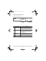
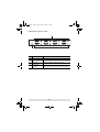
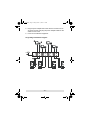
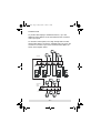
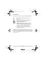
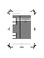
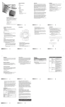
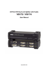
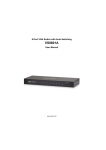
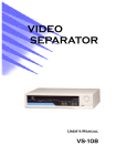
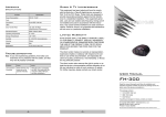
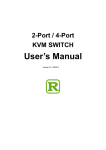
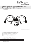
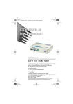
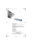
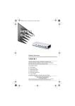
vs0404.fm Page 1 Friday, March 3, 2006 3:13 PM User Manual VS-0404 Read this guide thoroughly and follow the installation and operation procedures carefully in order to prevent any damage to the units and/or any devices that connect to them. This package contains: 1 Video Matrix Switch 1 VGA/Audio Cable (1.8m) 1 Power Adapter 1 Quick Start Guide 1 User Manual If anything is damaged or missing, contact your dealer. Copyright © 2006 ATEN® International Co., Ltd. Manual Part No. PAPE-1269-100G Printing Date: 03/2006 ATEN and the ATEN logo are trademarks of ATEN International Co., Ltd. All rights reserved. All other trademarks are the property of their respective owners. vs0404.fm Page 2 Friday, March 3, 2006 3:13 PM Note: This equipment has been tested and found to comply with the limits for a Class B digital device, pursuant to Part 15 of the FCC Rules. These limits are designed to provide reasonable protection against harmful interference in a residential installation. This equipment generates, uses and can radiate radio frequency energy, and if not installed and used in accordance with the instruction manual, may cause interference to radio communications. However, there is no guarantee that interference will not occur in a particular installation. If this equipment does cause harmful interference to radio or television reception, which can be determined by turning the equipment off and on, the user is encouraged to try to correct the interference by one or more of the following measures: Reorient or relocate the receiving antenna; Increase the separation between the equipment and receiver; Connect the equipment into an outlet on a circuit different from that which the receiver is connected; Consult the dealer or an experienced radio/television technician for help. This product is RoHS compliant. vs0404.fm Page 3 Friday, March 3, 2006 3:13 PM Overview The VS-0404 Video Matrix Switch combines the capability of a video switcher and signal splitter. It duplicates and enhances the video and audio signals from up to four input sources (computers), and routes them to up to four output devices (monitors, projectors, etc.). The VS-0404 provides fast, flexible, reliable solutions for installations that require audio-visual information from multiple sources to be delivered to multiple destinations – such as: Broadcasting information to public locations (news, airline and train schedule and arrival/departure information) Sporting events Theater and lecture overflow rooms Classroom and company training facilities Clearly marked front panel switches and LED indicators make it easy to link sources with desired output devices, creating a matrix of presentation possibilities. -3- vs0404.fm Page 4 Friday, March 3, 2006 3:13 PM Features Front panel push button switches select the combination of video input to video output. Duplicates and enhances video signals up to 65 m (max.) Cascadable Audio enabled Installation Requirements A VGA, SVGA, XGA or Multisync monitor capable of the highest resolution that you will be using on any computer in the installation for each output port you will be using. Speakers for each output port you will be using. A video cable with HDB-15 connectors (male on one end and female on the other end) for each computer you will be installing.* An audio cable for each computer you will be installing. -4- vs0404.fm Page 5 Friday, March 3, 2006 3:13 PM Hardware Overview VS-0404 Front View 1&2 No. Description 3 4 Function 1 Input Select Switches Each switch corresponds to an output port. Pressing the switch cycles through the input sources to select which input source’s signal will be sent to the switch’s corresponding output port. 2 Input Port LEDs The input source LEDs are built into the Selection Switches. Each switch has four numbered LEDs that correspond to the four input source ports. A lit LED indicates which input source is the currently selected one. 3 Source LEDs Each of these LEDs corresponds to an input port. A lit LED indicates data transmission from the source connected to its corresponding input port. 4 Power LED Lights to indicate that the unit is receiving power. -5- vs0404.fm Page 6 Friday, March 3, 2006 3:13 PM VS-0404 Rear View 1 3 2 No. Description Function 1 Video / Audio Output Ports The video and audio cables from the monitor and speakers plug in here (bottom row). 2 Power Jack The Power Adapter cable plugs in here. 3 Video / Audio Input Ports The video and audio cables from the computer’s video and audio output ports plug in here (top row). -6- vs0404.fm Page 7 Friday, March 3, 2006 3:13 PM Hardware Installation Before you Begin 1. Make sure that the power to all the devices you will be connecting up has been turned off. 2. Make sure that all devices you will be connecting up are properly grounded. Single Stage Setting up the VS-0404 is simply a matter of plugging in the cables. Refer to the Single Stage Installation Diagram: (the numbers in the diagram correspond to the numbered steps) and do the following: 1. Use a high density HDB-15 male/female VGA cable to connect the computer’s video port to any available video input source port on the VS-0404. 2. Use a male/male audio cable to connect the computer’s speaker port to the audio input source port that corresponds to the video input source port you connected in step 1. 3. Connect the monitor to any available video output port on the VS-0404. 4. Connect the speakers to the audio output port that corresponds to the video output port you connected in step 3 Note: 1. Repeat steps 1 - 4 for any other ports you wish to set up. 2. When connecting computers to the switch, we strongly recommend you use custom VGA/Audio Combination Cables like the one provided with this package – see Installation Requirements, p. 4, for details. -7- vs0404.fm Page 8 Friday, March 3, 2006 3:13 PM 5. Plug the power adapter that came with the VS-0404 into an AC power source, then plug the power adapter cable into the switch’s Power Jack. 6. Power on the attached equipment. Single Stage Installation Diagram: 3 4 5 1 2 -8- vs0404.fm Page 9 Friday, March 3, 2006 3:13 PM Cascading To provide video display to additional monitors, up to four additional video splitters can be cascaded from the VS-0404’s video ouput ports. To cascade a video splitter, use a high density HDB-15 male/ female VGA cable to connect any available video out port on the VS-0404 to the video in port of the cascaded video splitter, as shown in the diagram below: VS-0404 Cascaded Video Splitter VIDEO IN -9- vs0404.fm Page 10 Friday, March 3, 2006 3:13 PM Operation The VS-0404 operates according to the following parameters: Each front panel switch corresponds to an output port. Each switch selects the input source that will 4 3 2 1 display on the device connected to its corresponding output port. Pressing a switch takes you from the currently selected input port to the next one (1 to 2; 2 to 3; 3 to 4; 4 to 1). Press a switch as many times as necessary to select the desired input port. The built-in LEDs light to indicate which input port is the selected one. For example, if you want the data from Input Port 2, to be output to Output Port 4, press the switch that corresponds to Output Port 4 until the switch’s LED 2 lights to indicate that it is receiving data from Input Port 2. - 10 - vs0404.fm Page 11 Friday, March 3, 2006 3:13 PM Specifications Model VS-0404 PC - Monitor Connection Connectors LEDs 4-4 Out 4 x HDB-15 (female) 4 x 3.5mm Mini Stereo (female) In 4 x HDB-15 (male) 4 x 3.5mm Mini Stereo (female) Power DC Jack Power 1 (blue) Source 4 (green) Input 4 x 4 (green) Port Selection Switches 4 VGA Resolution 1920 x 1440@60Hz VGA DDC2B Support All Ports Signal Type VGA / SVGA / XGA Sync Range Sync Positive/Negative Power Supply DC 5.3V; 2.4A Power Consumption DC 5.3V; 12W Cable Distance Environment 65 meters maximum (VS-0404 to monitor) Operating Temp 0°~ 50°C Storage Temp Physical Properties -20°~ 60°C Humidity 0 ~ 80% RH, Non-condensing Housing Metal Weight 0.89 kg LxWxH 26.0 x 7.5 x 4.5 cm - 11 - vs0404.fm Page 12 Friday, March 3, 2006 3:13 PM VGA Pin Assignments Pin Signal Pin Signal Pin Signal 1 Red Video 6 Analog Ground 11 ID0 2 Green Video 7 Analog Ground 12 ID1 3 Blue Video 8 Analog Ground 13 Horizontal Sync 4 ID2 9 NC 14 Vertical Sync 5 Ground 10 Ground 15 ID3 Getting Help If you need to contact ATEN technical support with a problem, visit our website at www.aten.com. Limited Warranty IN NO EVENT SHALL THE DIRECT VENDOR'S LIABILITY EXCEED THE PRICE PAID FOR THE PRODUCT FROM THE DIRECT, INDIRECT, SPECIAL, INCIDENTAL OR CONSEQUENTIAL DAMAGES RESULTING FROM THE USE OF THE PRODUCT, DISK OR ITS DOCUMENTATION. The direct vendor makes no warranty or representation, expressed, implied, or statutory with respect to the contents or use of this documentation, and specially disclaims its quality, performance, merchantability, or fitness for any particular purpose. The direct vendor also reserves the right to revise or update the device or documentation without obligation to notify any individual or entity of such revisions, or update. For further inquires please contact your direct vendor. - 12 -